EP3299195A1 - Verfahren zur regelung einer klimaanlage für ein fahrzeug - Google Patents
Verfahren zur regelung einer klimaanlage für ein fahrzeug Download PDFInfo
- Publication number
- EP3299195A1 EP3299195A1 EP17193097.7A EP17193097A EP3299195A1 EP 3299195 A1 EP3299195 A1 EP 3299195A1 EP 17193097 A EP17193097 A EP 17193097A EP 3299195 A1 EP3299195 A1 EP 3299195A1
- Authority
- EP
- European Patent Office
- Prior art keywords
- air
- flow
- unit
- outside air
- opening degree
- Prior art date
- Legal status (The legal status is an assumption and is not a legal conclusion. Google has not performed a legal analysis and makes no representation as to the accuracy of the status listed.)
- Granted
Links
Images
Classifications
-
- B—PERFORMING OPERATIONS; TRANSPORTING
- B60—VEHICLES IN GENERAL
- B60H—ARRANGEMENTS OF HEATING, COOLING, VENTILATING OR OTHER AIR-TREATING DEVICES SPECIALLY ADAPTED FOR PASSENGER OR GOODS SPACES OF VEHICLES
- B60H1/00—Heating, cooling or ventilating devices
- B60H1/00642—Control systems or circuits; Control members or indication devices for heating, cooling or ventilating devices
- B60H1/00814—Control systems or circuits characterised by their output, for controlling particular components of the heating, cooling or ventilating installation
- B60H1/00821—Control systems or circuits characterised by their output, for controlling particular components of the heating, cooling or ventilating installation the components being ventilating, air admitting or air distributing devices
- B60H1/00835—Damper doors, e.g. position control
- B60H1/00849—Damper doors, e.g. position control for selectively commanding the induction of outside or inside air
-
- B—PERFORMING OPERATIONS; TRANSPORTING
- B60—VEHICLES IN GENERAL
- B60H—ARRANGEMENTS OF HEATING, COOLING, VENTILATING OR OTHER AIR-TREATING DEVICES SPECIALLY ADAPTED FOR PASSENGER OR GOODS SPACES OF VEHICLES
- B60H1/00—Heating, cooling or ventilating devices
- B60H1/00642—Control systems or circuits; Control members or indication devices for heating, cooling or ventilating devices
- B60H1/00735—Control systems or circuits characterised by their input, i.e. by the detection, measurement or calculation of particular conditions, e.g. signal treatment, dynamic models
-
- B—PERFORMING OPERATIONS; TRANSPORTING
- B60—VEHICLES IN GENERAL
- B60H—ARRANGEMENTS OF HEATING, COOLING, VENTILATING OR OTHER AIR-TREATING DEVICES SPECIALLY ADAPTED FOR PASSENGER OR GOODS SPACES OF VEHICLES
- B60H1/00—Heating, cooling or ventilating devices
- B60H1/00642—Control systems or circuits; Control members or indication devices for heating, cooling or ventilating devices
- B60H1/00814—Control systems or circuits characterised by their output, for controlling particular components of the heating, cooling or ventilating installation
- B60H1/00821—Control systems or circuits characterised by their output, for controlling particular components of the heating, cooling or ventilating installation the components being ventilating, air admitting or air distributing devices
- B60H1/00864—Ventilators and damper doors
-
- B—PERFORMING OPERATIONS; TRANSPORTING
- B61—RAILWAYS
- B61D—BODY DETAILS OR KINDS OF RAILWAY VEHICLES
- B61D27/00—Heating, cooling, ventilating, or air-conditioning
- B61D27/0018—Air-conditioning means, i.e. combining at least two of the following ways of treating or supplying air, namely heating, cooling or ventilating
-
- B—PERFORMING OPERATIONS; TRANSPORTING
- B60—VEHICLES IN GENERAL
- B60H—ARRANGEMENTS OF HEATING, COOLING, VENTILATING OR OTHER AIR-TREATING DEVICES SPECIALLY ADAPTED FOR PASSENGER OR GOODS SPACES OF VEHICLES
- B60H1/00—Heating, cooling or ventilating devices
- B60H1/00642—Control systems or circuits; Control members or indication devices for heating, cooling or ventilating devices
- B60H1/00735—Control systems or circuits characterised by their input, i.e. by the detection, measurement or calculation of particular conditions, e.g. signal treatment, dynamic models
- B60H1/00792—Arrangement of detectors
Definitions
- the invention relates to a method for controlling an air conditioning system for a vehicle, an air conditioning system for a vehicle and a vehicle with an air conditioning system.
- air conditioning systems are used to produce comfort conditions in terms of a temperature and humidity in rooms for passengers and / or staff.
- As a means of transmission for the temperature and humidity usually air is used.
- an air conditioning by a Zu Kunststoffgebläse an air conditioner draws mixed air from circulating air and outside air into the air conditioner, said mixed air is then cooled or heated in the air conditioner and then supplied as supply air to a room to be air conditioned.
- An exhaust air volume flow the amount of which corresponds to a supply air volume flow, leaves the room to be conditioned via separate exhaust air openings on the vehicle.
- an outdoor air volume flow This can be constant, e.g. for driver's cabs, or depending on an outside temperature, e.g. for passenger spaces.
- the ratio of outside air to recirculated air is adjusted by means of flap devices in the vehicle, wherein the adjustment of the flap devices during a system test is carried out at a vehicle standstill.
- the outside air flow is throttled via an outside air flap.
- the publication EP 2 678 176 B1 describes an air conditioning system for a vehicle, wherein in the air conditioning system, three operating states are possible: a fresh air mode, a recirculation mode and a mixed air mode.
- a mixed air operation a predetermined mixing ratio between a fresh air quantity and a recirculated air volume is set by means of a pressure measurement in a fresh air duct or a recirculating air duct and a fresh air flap.
- a recirculation damper is fully open.
- the disadvantage here is that a mixing ratio between the amount of fresh air and the circulating air quantity is predetermined and remains constant at each speed of the vehicle.
- the air conditioner has a high power requirement.
- the publication DE 198 47 504 C1 discloses a method for controlling outside air and recirculating air flow in a ventilation system for a vehicle. According to the occupation of the vehicle, a certain outside air flow is sucked. In addition, a circulating air flow can be supplied from the interior. Both flows are mixed, whereby a minimum outside air proportion is determined, for example, as a function of a room air temperature or a number of persons in a room.
- the disadvantage here is that the air quality is determined by a variety of physical quantities.
- the invention is therefore based on the object to provide a method for controlling an air conditioner, in which a given air quality is easily maintained, a power consumption of the air conditioner is minimized and any mixing ratio of an outside air flow and a recirculating air flow is set.
- the object is achieved in a method for controlling an air conditioning system for a vehicle in which at least one mixed air flow flows into at least one air conditioner and at least one supply air flows out of the air conditioner, wherein at least one flow actual value is determined in at least one outside air duct and at least a control unit as a function of the actual flow value continuously adjusts at least a first opening degree for at least one outside air flap unit and adjusts at least one second opening degree for at least one recirculating air flap unit independently of the first opening degree.
- the control unit also infinitely adjusts the second opening degree depending on the actual flow value, and at least one combination of a first opening degree with a second opening degree establishes a flow value in the outside air passage that corresponds to a predetermined flow target value.
- the advantage of this method is that an influencing of the actual flow value in the outside air duct takes place with the aid of the first opening degree of the outside air flap unit and the second opening degree of the recirculating air flap unit.
- the influencing takes place with the aid of a separate regulation of the outside air flap unit and the recirculating air flap unit.
- a reduction of the actual flow value below a predetermined minimum value is prevented.
- a predetermined air quality is maintained.
- a power requirement of the air conditioning system is minimized.
- the control unit controls both the outside air flap unit and the recirculating air flap unit continuously and independently of each other and produces a adapted to a driving operation desired mixing ratio between the outside air flow and the circulating air flow. The mixing ratio is thus variable.
- At least one outside air flow is adjusted by means of the outside air flap unit and at least one recirculation air flow by means of the recirculating air flap unit as required and produce the mixed air flow in any desired mixing ratio, including the case where a mixing proportion of the outside air flow or the recirculating air flow is zero.
- the mixing ratio can thus be adapted advantageously to any speed of the vehicle and related external pressure conditions between an outside air intake and an exhaust air outlet become.
- the mixing ratio can be adapted to any climatic conditions outside and inside the vehicle.
- the degree of opening of the outside air flap is increased, wherein the degree of opening of the recirculation flap is reduced and / or a speed of a supply air fan unit of the air conditioner is increased. In this way, the actual flow value in the outside air duct is increased, so that the minimum value is maintained.
- the degree of opening of the recirculating air flap unit may also be zero, i. the recirculation damper unit is completely closed (pure outside air operation).
- the degree of opening of the outside air flap unit is reduced, whereby the degree of opening of the recirculating air flap unit is increased and / or the speed of the supply air fan unit is reduced. In this way, the actual flow value in the outside air duct is reduced so that the actual flow value remains below the maximum value.
- the opening degree of the outside air damper unit may also be zero, i. the outside air damper unit is completely closed (pure recirculation mode).
- control unit controls the speed of Zu Kunststoffventilatorü independent of the outside air flap unit and the recirculating air flap unit.
- This offers the advantage that an intake quantity of the mixed airflow can be set independently of the mixing ratio between the outside airflow and the recirculating airflow. This expands the setting options of the air conditioning system.
- control unit can regulate the speed of the Zu povertyventilatorü in stages or continuously. So you can choose different types of control.
- control unit can adjust the speed of the Zu Kunststoffventilatoraji depending on an outdoor temperature, a circulating air temperature and / or a room temperature in a room to be air conditioned. This represents an advantageous way of controlling the speed.
- an air conditioner for a vehicle for carrying out the method according to the invention which comprises the air conditioner and in which the outside air flap unit between the outside air duct and at least one mixed air duct and the Recirculating air flap unit are arranged between at least one recirculating air duct and the mixed air duct, wherein at least one control unit is coupled to at least one flow sensor in the outside air duct and at least one stepless first adjusting device for the outside air flap unit.
- the control unit is coupled to at least a second stepless adjustment device for the recirculating air flap unit, and any combination of any first opening degree of the outside air flap unit and any second opening degree of the recirculating air flap unit is adjustable.
- the advantage of the air conditioner is that it allows the implementation of the method according to the invention.
- the separate adjustment means for the first opening degree and the second opening degree allow separate adjustment of the outside air flow and the recirculation air flow. This can prevent that under unfavorable operating conditions or pressure conditions of the flow actual value falls below the required minimum value or increases above the maximum value.
- any desired mixing ratio between the outside air flow and the recirculating air flow can be adjusted.
- the flow sensor is preferably a mass flow sensor, a volume flow sensor or a differential pressure sensor. This type of sensor is particularly well suited for determining the actual flow value in the outside air duct. However, other flow sensors may be used.
- the flow sensor can be arranged at any position in the outside air duct.
- the position of the flow sensor can be set at any position between an outer opening of the outer air duct and the outer air damper unit and on a wall or in an inner space of the outer air duct.
- the outer air channel may have at least one non-return valve. This is an additional measure to prevent a complete or partial escape of the recirculating air flow from the vehicle at extreme pressure differences between the openings for the Jardin Kunststoffansaugung and the exhaust air outlet.
- at least two pressure sensors can be arranged to determine a flow direction in the outside air duct. With the help of the pressure sensors, the flow direction of an air flow in the outside air duct can be determined. If this air flow points outward, ie out of the vehicle, it can be adjusted by adjusting the outside air flap unit and the recirculating air flap unit, the air flow can be adjusted so that the actual flow value again reaches and adheres to the minimum value and points the direction of flow into the vehicle.
- the outside air duct may have at least one intake grille. As a result, the outside air flow is pre-cleaned.
- Also claimed is a vehicle, in particular a rail vehicle, with the air conditioning system according to the invention.
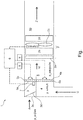
- the figure shows a schematic sectional view of an air conditioner 1 for an otherwise not shown rail vehicle.
- the air conditioner 1 comprises an air conditioner 2, an outside air duct 3, a recirculating air duct 4, a mixed air duct 5 and a supply air duct 10.
- the air conditioner 1 has a control unit 6.
- the outside air channel 3 adjoins an outside air flap unit 3a having a plurality of first fins 3b and an intake grate 3c. Furthermore, the outside air duct 3 can be provided with a non-return flap 3d on the intake grate 3c.
- the outside air damper unit 3a is disposed between the outside air duct 3 and the mixed air duct 5.
- the intake grille 3 c is located between an outer periphery of the rail vehicle and the outer air passage 3.
- the circulating air channel 4 begins in a room, not shown, to be conditioned and ends at a recirculating air flap unit 4a with a plurality of second blades 4b.
- the circulating air flap unit 4a is arranged between the circulating air channel 4 and the mixed air channel 5.
- the mixed air channel 5 extends from the outside air flap unit 3 a and the recirculating air flap unit 4 a to the air conditioner 2.
- the air conditioner 2 comprises a filter unit 2a, an evaporator unit 2b, a supply air fan unit 2c and a heating unit 2d, which are arranged in the order mentioned between the mixed air duct 5 and the supply air duct 10. The order can also be chosen differently.
- the heating unit 2d is also suitable for cooling.
- the supply air duct 10 opens into the room to be conditioned.
- the control unit 6 is signal technically connected to a flow sensor 7, which is arranged at an arbitrary position in the outside air duct 3. It is also possible to arrange a plurality of flow sensors 7 in the outside air duct 3. At least one flow sensor 7 may also be arranged in the circulating air channel 4. Furthermore, the control unit is signal technically connected to a first adjusting device 8 and a second adjusting device 9. The first adjusting device 8 is infinitely adjustable and control technically connected to the first fins 3b of the outside air flap unit 3a. The second adjusting device 9 is infinitely adjustable and control technically connected to the second fins 4b of the recirculating air flap unit 4a. The control unit 6 may also be connected by control technology with a speed control device, not shown in the figure, the Zu povertyventilatortician 2c.
- the flow sensor 7 measures a flow actual value.
- the actual flow value can be a mass flow, a volume flow or a pressure difference. Other types of actual flow values are also possible.
- the actual flow value is forwarded to the control unit 6.
- the control unit 6 determines on the basis of the actual flow value a required first opening degree of the outside air flap unit 3a, a required second opening degree of the recirculating air flap unit 4a and optionally a required speed value for the supply air fan unit 2c. Subsequently, the control unit 6 outputs corresponding control signals to the first adjusting device 8, the second adjusting device 9 and optionally to the speed control device of the Zu povertyventilatortician 2c.
- the size of the outside air flow A flowing into the mixed air channel 5 is adjusted.
- the second opening degree of the recirculating-air flap unit 4 a the size of the recirculating air stream U flowing into the mixed-air channel 5 is set. Due to the speed control of the Zu povertyventilatortician 2c can also be set an intake of the mixed air flow M.
- the Zu povertyventilatortician 2c can be controlled continuously or in stages. The settings are made in each case depending on air conditioning requirements during a driving operation of the rail vehicle.
- a pressure in the outside air duct 3 is influenced by an ambient pressure or external pressure p_out outside the rail vehicle. Due to pressure differences between the outside air duct 3 and the circulating air duct 4 with a pressure p_Um Kunststoff and the mixed air duct 5 with a pressure p_saugseite normally results in an outside air flow A to the air conditioner 2 out.
- In the outside air duct 3 may be an overpressure or a negative pressure while driving.
- the first opening degree of the outside air flap unit 3a is increased until the required flow setpoint is reached again. It is possible to additionally reduce the second opening degree of the recirculating-air flap unit 4a and / or to increase the rotational speed of the supply-air fan unit 2c.
- the first opening degree of the outside air flap unit 3a is reduced until the required flow setpoint is reached again. It is possible to additionally increase the second opening degree of the recirculating air flap unit 4a and / or to reduce the rotational speed of the supply air fan unit 2c.
- the outside air damper unit 3a, the recirculation damper unit 4a and the supply air fan unit 2c can basically be controlled independently of each other. Associated control values are not necessarily in a specific relationship to each other.
- the flow setpoint is predetermined and ranges from a minimum value to a maximum value. Normally, the flow setpoint is the minimum value. Falling below the minimum value, the indoor air quality deteriorates significantly in the room to be air-conditioned. When the maximum value is exceeded, a higher energy requirement for air conditioning of the outside air flow A is required.
- the minimum value, the maximum value and the flow setpoint can each have tolerances.
- the non-return valve 3d can prevent a return flow in the outside air duct 3 from occurring or at least part of the circulating air flow U escaping. Thus, a backflow in the outside air duct 3 or an escape of at least part of the circulating air flow U through the outside air duct 3 is prevented.
- at least two pressure sensors which are independent of each other can be arranged in the outside air duct (not shown in the figure), which are likewise signal-wise coupled to the control unit 6. With the help of these two pressure sensors, a flow direction in the outside air duct 3 can be determined. If the flow direction in the outside air duct 3 to the outside, i. towards the environment of the rail vehicle, the control unit 6 may throttle the recirculation damper unit 4a to return the outside air flow A to the flow set point and the required flow direction, i.e., the flow rate. in the vehicle, to regulate.
- the intake grate 3 c is used for pre-cleaning of air that enters the outside air channel 3 from the outside.
Landscapes
- Engineering & Computer Science (AREA)
- Mechanical Engineering (AREA)
- Physics & Mathematics (AREA)
- Thermal Sciences (AREA)
- Air-Conditioning For Vehicles (AREA)
Abstract
Description
- Die Erfindung betrifft ein Verfahren zur Regelung einer Klimaanlage für ein Fahrzeug, eine Klimaanlage für ein Fahrzeug und ein Fahrzeug mit einer Klimaanlage.
- Bei Fahrzeugen, z.B. Schienenfahrzeugen, werden Klimaanlagen eingesetzt, um in Räumen für Fahrgäste und/oder Personal Komfortbedingungen bezüglich einer Temperatur und einer Luftfeuchte herzustellen. Als Übertragungsmittel für die Temperatur und die Luftfeuchte wird in der Regel Luft verwendet.
- Üblicherweise erfolgt eine Klimatisierung, indem ein Zuluftgebläse eines Klimageräts Mischluft aus Umluft und Außenluft in das Klimagerät einsaugt, wobei diese Mischluft anschließend im Klimagerät gekühlt oder aufgeheizt und dann als Zuluft einem zu klimatisierenden Raum zugeführt wird. Ein Fortluftvolumenstrom, dessen Betrag einem Zuluftvolumenstrom entspricht, verlässt den zu klimatisierenden Raum über separate Fortluftöffnungen am Fahrzeug.
- Zur Gewährleistung einer vorgegebenen Raumluftqualität kann es erforderlich sein, einen Mindestwert für einen Außenluftvolumenstrom sicher zu stellen. Dieser kann konstant sein, z.B. für Führerräume, oder in Abhängigkeit von einer Außentemperatur eingestellt werden, z.B. für Fahrgasträume. Das Verhältnis von Außenluft zu Umluft wird mittels Klappeneinrichtungen im Fahrzeug eingestellt, wobei die Einstellung der Klappeneinrichtungen während eines Systemtestes bei einem Fahrzeugstillstand vorgenommen wird. Üblicherweise wird dabei der Außenluftstrom über eine Außenluftklappe angedrosselt.
- Aufgrund von Druckdifferenzen zwischen einer vor dem Klimagerät angeordneten Mischluftkammer und einem Außenluftkanal bzw. einem Umluftkanal ergibt sich normalerweise ein Außenluftstrom in Richtung zum Klimagerät hin.
- Aufgrund von Druckänderungen an einer Außenluftansaugung und einem Fortluftaustritt kann es im Fahrbetrieb zu unerwünschten Änderungen des Betrags des Außenluftvolumenstromes kommen. Bei Überdruck an der Außenluftansaugung kommt es zu einem erhöhten Betrag des Außenluftvolumenstroms, der einen erhöhten Leistungsbedarf der Klimaanlage nach sich ziehen kann. Sinkt der Druck an der Außenluftansaugung im Fahrbetrieb dagegen deutlich ab, kommt es zu einer Änderung des Mischungsverhältnisses zwischen der Außenluft und der Umluft. Dies kann bei ungünstigen Druckverhältnissen dazu führen, dass der Außenluftvolumenstrom unter den geforderten Mindestwert absinkt. Dabei verschlechtert sich die Raumluftqualität im zu klimatisierenden Raum deutlich Im Extremfall tritt Umluft durch eine Außenluftklappe der Außenluftansaugung in die Umgebung des Fahrzeugs aus. Dabei tritt ungereinigte Luft über den Forlulftaustritt in das Fahrzeug ein. Dies kann zu Problemen bei der Einhaltung hygienischer Anforderungen führen.
- Die Druckschrift
EP 2 678 176 B1 beschreibt ein Klimaanlagensystem für ein Fahrzeug, wobei in dem Klimaanlagensystem drei Betriebszustände möglich sind: ein Frischluftbetrieb, ein Umluftbetrieb und ein Mischluftbetrieb. Bei einem Mischluftbetrieb wird mit Hilfe einer Druckmessung in einem Frischluftkanal bzw. einem Umluftkanal und einer Frischluftklappe ein vorgegebenes Mischungsverhältnis zwischen einer Frischluftmenge und einer Umluftmenge eingestellt. Dabei ist eine Umluftklappe vollständig geöffnet. Nachteilig ist hierbei, dass ein Mischungsverhältnis zwischen der Frischluftmenge und der Umluftmenge vorgegeben ist und bei jeder Geschwindigkeit des Fahrzeugs konstant bleibt. Außerdem weist die Klimaanlage einen hohen Leistungsbedarf auf. - Die Druckschrift
DE 198 47 504 C1 offenbart ein Verfahren zur Steuerung von Außenluft- und Umluftstrom in einer raumlufttechnischen Anlage für ein Fahrzeug. Entsprechend der Besetzung des Fahrzeugs wird ein bestimmter Außenluftstrom angesaugt. Zusätzlich kann ein Umluftstrom aus dem Innenraum zugeführt werden Beide Ströme werden gemischt, wobei ein Mindestaußenluftanteil z.B. in Abhängigkeit von einer Raumlufttemperatur oder einer Zahl von Personen in einem Raum festgelegt wird. Nachteilig ist dabei, dass die Luftqualität durch eine Vielzahl von physikalischen Größen bestimmt wird. - Der Erfindung liegt daher die Aufgabe zu Grunde ein Verfahren zur Regelung einer Klimaanlage bereit zu stellen, bei dem eine vorgegebene Luftqualität einfach eingehalten wird, ein Leistungsbedarf der Klimaanlage minimiert wird und ein beliebiges Mischungsverhältnis von einem Außenluftstrom und einem Umluftstrom eingestellt wird.
- Diese Aufgabe wird erfindungsgemäß mit einem Verfahren zur Regelung einer Klimaanlage für ein Fahrzeug nach Anspruch 1 gelöst. Weiterhin wird die Aufgabe mit einer Klimaanlage für ein Fahrzeug zur Durchführung des Verfahrens nach Anspruch 8 gelöst. Vorteilhafte Ausgestaltungen der Erfindung sind in den Unteransprüchen enthalten.
- Erfindungsgemäß besteht die Lösung der Aufgabe in einem Verfahren zur Regelung einer Klimaanlage für ein Fahrzeug, bei dem mindestens ein Mischluftstrom in mindestens ein Klimagerät einströmt und mindestens ein Zuluftstrom aus dem Klimagerät ausströmt, wobei mindestens ein Strömungs-Istwert in mindestens einem Außenluftkanal ermittelt wird und mindestens eine Regelungseinheit in Abhängigkeit von dem Strömungs-Istwert mindestens einen ersten Öffnungsgrad für mindestens eine Außenluftklappeneinheit stufenlos einstellt und mindestens einen zweiten Öffnungsgrad für mindestens eine Umluftklappeneinheit unabhängig von dem ersten Öffnungsgrad einstellt. Die Regelungseinheit stellt auch den zweiten Öffnungsgrad in Abhängigkeit von dem Strömungs-Istwert stufenlos ein, und mindestens eine Kombination eines ersten Öffnungsgrades mit einem zweiten Öffnungsgrad stellt einen Strömungs-istwert im Außenluftkanal her, der einem vorgegebenen Strömungs-Sollwert entspricht.
- Der Vorteil dieses Verfahrens besteht darin, dass eine Beeinflussung des Strömungs-Istwerts im Außenluftkanal mit Hilfe des ersten Öffnungsgrades der Außenluftklappeneinheit und des zweiten Öffnungsgrades der Umluftklappeneinheit erfolgt. Die Beeinflussung erfolgt mit Hilfe einer getrennten Regelung der Außenluftklappeneinheit und der Umluftklappeneinheit. Eine Verringerung des Strömungs-Istwerts unter einen vorgegebenen Minimalwert wird verhindert. Dadurch wird eine vorgegebene Luftqualität eingehalten. Außerdem wird verhindert, dass der Strömungs-Istwert einen vorgegebenen Maximalwert überschreitet. Dadurch wird ein Leistungsbedarf der Klimaanlage minimiert.. Die Regelungseinheit regelt sowohl die Außenluftklappeneinheit als auch die Umluftklappeneinheit stufenlos und unabhängig voneinander und stellt ein an einen Fahrbetrieb angepasstes gewünschtes Mischungsverhältnis zwischen dem Außenluftstrom und dem Umluftstrom her. Das Mischungsverhältnis ist somit variabel.
- Gemäß einer bevorzugten Durchführung des erfindungsgemäßen Verfahrens werden mindestens ein Außenluftstrom mittels der Außenluftklappeneinheit und mindestens ein Umluftstrom mittels der Umluftklappeneinheit nach Bedarf eingestellt und erzeugen in jedem gewünschten Mischungsverhältnis den Mischluftstrom, einschließlich dem Fall, dass ein Mischungsanteil des Außenluftstroms oder des Umluftstroms gleich Null ist. Das Mischungsverhältnis kann somit vorteilhaft an jede Geschwindigkeit des Fahrzeugs und damit in Verbindung stehende Außendruckverhältnisse zwischen einer Außenluftansaugung und einem Fortluftaustritt angepasst werden. Außerdem kann das Mischungsverhältnis an jede klimatische Gegebenheit außerhalb und innerhalb des Fahrzeugs angepasst werden.
- In einer zweckmäßigen Ausführung der Erfindung wird der Öffnungsgrad der Außenluftklappe erhöht, wobei der Öffnungsgrad der Umluftklappe verringert und/oder eine Drehzahl einer Zuluftventilatoreinheit des Klimagerätes erhöht wird. Auf diese Weise wird der Strömungs-Istwert im Außenluftkanal erhöht, so dass der Minimalwert eingehalten wird. Der Öffnungsgrad der Umluftklappeneinheit kann auch Null betragen, d.h. die Umluftklappeneinheit wird vollständig geschlossen (reiner Außenluftbetrieb).
- In einer weiteren zweckmäßigen Ausführung der Erfindung wird der Öffnungsgrad der Außenluftklappeneinheit verringert, wobei der Öffnungsgrad der Umluftklappeneinheit erhöht und/oder die Drehzahl der Zuluftventilatoreinheit verringert wird. Auf diese Weise wird der Strömungs-Istwert im Außenluftkanal verringert, so dass der Strömungs-Istwert unterhalb des Maximalwerts bleibt. Der Öffnungsgrad der Außenluftklappeneinheit kann auch Null betragen, d.h. die Außenluftklappeneinheit wird vollständig geschlossen (reiner Umluftbetrieb).
- In einer speziellen Weiterbildung der Erfindung regelt die Regelungseinheit die Drehzahl der Zuluftventilatoreinheit unabhängig von der Außenluftklappeneinheit und der Umluftklappeneinheit. Dies bietet den Vorteil, dass eine Ansaugmenge des Mischluftstroms unabhängig von dem Mischungsverhältnis zwischen dem Außenluftstrom und dem Umluftstrom eingestellt werden kann. Dadurch werden die Einstellmöglichkeiten der Klimaanlage erweitert.
- Speziell kann die Regelungseinheit die Drehzahl der Zuluftventilatoreinheit in Stufen oder stufenlos regeln. Es können also verschiedene Regelungsarten gewählt werden.
- Weiterhin kann die Regelungseinheit die Drehzahl der Zuluftventilatoreinheit in Abhängigkeit von einer Außentemperatur, einer Umlufttemperatur und/oder einer Raumtemperatur in einem zu klimatisierenden Raum einstellen. Dies stellt eine vorteilhafte Art einer Regelung der Drehzahl dar.
- Weiterhin besteht die Lösung der Aufgabe in einer Klimaanlage für ein Fahrzeug zur Durchführung des erfindungsgemäßen Verfahrens, die das Klimagerät umfasst und bei der die Außenluftklappeneinheit zwischen dem Außenluftkanal und mindestens einem Mischluftkanal und die Umluftklappeneinheit zwischen mindestens einem Umluftkanal und dem Mischluftkanal angeordnet sind, wobei mindestens eine Regelungseinheit mit mindestens einem Strömungssensor im Außenluftkanal und mindestens einer stufenlosen ersten Einstelleinrichtung für die Außenluftklappeneinheit gekoppelt ist. Die Regelungseinheit ist mit mindestens einer zweiten stufenlosen Einstelleinrichtung für die Umluftklappeneinheit gekoppelt, und es ist jede Kombination von einem beliebigen ersten Öffnungsgrad der Außenluftklappeneinheit und einem beliebigen zweiten Öffnungsgrad der Umluftklappeneinheit einstellbar.
- Der Vorteil der Klimaanlage besteht darin, dass diese die Durchführung des erfindungsgemäßen Verfahrens ermöglicht. Die getrennten Einstelleinrichtungen für den ersten Öffnungsgrad und den zweiten Öffnungsgrad erlauben eine getrennte Einstellung des Außenluftstroms und des Umluftstroms. Dadurch kann verhindert werden, dass bei ungünstigen Betriebsbedingungen bzw. Druckverhältnissen der Strömungs-Istwert unter den erforderlichen Minimalwert abfällt oder über den Maximalwert ansteigt. Zudem kann ein beliebiges gewünschtes Mischungsverhältnis zwischen dem Außenluftstrom und dem Umluftstrom eingestellt werden.
- Vorzugsweise ist der Strömungssensor ein Massenstromsensor, ein Volumenstromsensor oder ein Differenzdrucksensor. Diese Art von Sensoren ist besonders gut geeignet, um den Strömungs-Istwert im Außenluftkanal zu ermitteln. Es können jedoch auch andere Strömungssensoren verwendet werden.
- Außerdem kann der Strömungssensor an einer beliebigen Position im Außenluftkanal angeordnet sein. Somit kann die Position des Strömungssensors an jeder Stelle zwischen einer Außenöffnung des Außenluftkanals und der Außenluftklappeneinheit sowie an einer Wand oder in einem Innenraum des Außenluftkanals festgelegt werden.
- Weiterhin kann der Außenluftkanal mindestens eine Rückschlagklappe aufweisen. Dies ist eine zusätzliche Maßnahme um bei extremen Druckdifferenzen zwischen den Öffnungen für die Außenluftansaugung und den Fortluftaustritt einen vollständigen oder teilweisen Austritt des Umluftstroms aus dem Fahrzeug zu verhindern.
Alternativ zu der Rückschlagklappe können mindestens zwei Drucksensoren zur Ermittlung einer Strömungsrichtung im Außenluftkanal angeordnet sein. Mit Hilfe der Drucksensoren kann die Strömungsrichtung eines Luftstromes im Außenluftkanal festgestellt werden. Weist dieser Luftstrom nach außen, d.h. aus dem Fahrzeug heraus, kann durch ein Verstellen der Außenluftklappeneinheit und der Umluftklappeneinheit der Luftstrom so eingestellt werden, dass der Strömungs-Istwert wieder den Minimalwert erreicht und einhält und die Strömungsrichtung in das Fahrzeug hinein weist. - Zusätzlich kann der Außenluftkanal mindestens ein Ansauggitter aufweisen. Dadurch wird der Außenluftstrom vorgereinigt.
- Beansprucht wird außerdem ein Fahrzeug, insbesondere ein Schienenfahrzeug, mit der erfindungsgemäßen Klimaanlage.
- Im Folgenden wird ein Ausführungsbeispiel der Erfindung anhand von einer einzigen Figur näher erläutert. Es zeigen:
- Fig. 1
- eine schematische Schnittansicht einer erfindungsgemäßen Klimaanlage.
- Die Figur zeigt eine schematische Schnittansicht einer Klimaanlage 1 für ein ansonsten nicht weiter dargestelltes Schienenfahrzeug. Die Klimaanlage 1 umfasst ein Klimagerät 2, einen Außenluftkanal 3, einen Umluftkanal 4, einen Mischluftkanal 5 und einen Zuluftkanal 10. Außerdem weist die Klimaanlage 1 eine Regelungseinheit 6 auf.
- Der Außenluftkanal 3 grenzt an eine Außenluftklappeneinheit 3a mit einer Vielzahl von ersten Lamellen 3b sowie an ein Ansauggitter 3c an. Weiterhin kann der Außenluftkanal 3 mit einer Rückschlagklappe 3d am Ansauggitter 3c versehen sein. Die Außenluftklappeneinheit 3a ist zwischen dem Außenluftkanal 3 und dem Mischluftkanal 5 angeordnet. Das Ansauggitter 3c befindet sich zwischen einer äußeren Umgebung des Schienenfahrzeugs und dem Außenluftkanal 3.
- Der Umluftkanal 4 beginnt in einem nicht dargestellten zu klimatisierenden Raum und endet an einer Umluftklappeneinheit 4a mit einer Vielzahl von zweiten Lamellen 4b. Die Umluftklappeneinheit 4a ist zwischen dem Umluftkanal 4 und dem Mischluftkanal 5 angeordnet.
- Der Mischluftkanal 5 verläuft von der Außenluftklappeneinheit 3a und der Umluftklappeneinheit 4a bis zum Klimagerät 2.
- Das Klimagerät 2 umfasst eine Filtereinheit 2a, eine Verdampfereinheit 2b, eine Zuluftventilatoreinheit 2c und eine Heizeinheit 2d, die in der genannten Reihenfolge zwischen dem Mischluftkanal 5 und dem Zuluftkanal 10 angeordnet sind. Die Reihenfolge kann jedoch auch anders gewählt werden. Die Heizeinheit 2d ist auch zum Kühlen geeignet. Der Zuluftkanal 10 mündet in den zu klimatisierenden Raum.
- Die Regelungseinheit 6 ist signaltechnisch mit einem Strömungssensor 7 verbunden, der an einer beliebigen Position im Außenluftkanal 3 angeordnet ist. Es können auch mehrere Strömungssensoren 7 im Außenluftkanal 3 angeordnet sein. Es kann auch mindestens ein Strömungssensor 7 im Umluftkanal 4 angeordnet sein. Weiterhin ist die Regelungseinheit signaltechnisch mit einer ersten Einstelleinrichtung 8 und einer zweiten Einstelleinrichtung 9 verbunden. Die erste Einstelleinrichtung 8 ist stufenlos verstellbar und regelungstechnisch mit den ersten Lamellen 3b der Außenluftklappeneinheit 3a verbunden. Die zweite Einstelleinrichtung 9 ist stufenlos verstellbar und regelungstechnisch mit den zweiten Lamellen 4b der Umluftklappeneinheit 4a verbunden. Die Regelungseinheit 6 kann außerdem mit einer in der Figur nicht dargestellten Drehzahlregelungseinrichtung der Zuluftventilatoreinheit 2c regelungstechnisch verbunden sein.
- Im Betrieb befinden sich ein Außenluftstrom A im Außenluftkanal 3, ein Umluftstrom U im Umluftkanal 4, ein Mischluftstrom M im Mischluftkanal 5 und ein Zuluftstrom Z im Zuluftkanal 10. Im Außenluftkanal 3 misst der Strömungssensor 7 einen Strömungs-Istwert. Der Strömungs-Istwert kann ein Massenstrom, ein Volumenstrom oder eine Druckdifferenz sein. Weitere Arten von Strömungs-Istwerten sind ebenfalls möglich. Der Strömungs-Istwert wird an die Regelungseinheit 6 weitergegeben. Die Regelungseinheit 6 ermittelt anhand des Strömungs-Istwertes einen benötigten ersten Öffnungsgrad der Außenluftklappeneinheit 3a, einen benötigten zweiten Öffnungsgrad der Umluftklappeneinheit 4a und gegebenenfalls einen benötigten Drehzahlwert für die Zuluftventilatoreinheit 2c. Anschließend gibt die Regelungseinheit 6 entsprechende Regelungssignale an die erste Einstelleinrichtung 8, die zweite Einstelleinrichtung 9 und gegebenenfalls an die Drehzahlregelungseinrichtung der Zuluftventilatoreinheit 2c.
- Durch eine Veränderung des ersten Öffnungsgrades der Außenluftklappeneinheit 3a wird die in den Mischluftkanal 5 einströmende Größe des Außenluftstromes A eingestellt. Durch eine Veränderung des zweiten Öffnungsgrades der Umluftklappeneinheit 4a wird die in den Mischluftkanal 5 einströmende Größe des Umluftstromes U eingestellt. Durch die Drehzahlregelung der Zuluftventilatoreinheit 2c kann außerdem eine Ansaugmenge des Mischluftstromes M eingestellt werden. Die Zuluftventilatoreinheit 2c kann stufenlos oder in Stufen angesteuert werden. Die Einstellungen erfolgen jeweils in Abhängigkeit von Klimatisierungsanforderungen während eines Fahrbetriebs des Schienenfahrzeugs.
- Ein Druck im Außenluftkanal 3 wird von einem Umgebungsdruck bzw. Außendruck p_außen außerhalb des Schienenfahrzeugs beeinflusst. Aufgrund von Druckdifferenzen zwischen dem Außenluftkanal 3 bzw. dem Umluftkanal 4 mit einem Druck p_Umluft und dem Mischluftkanal 5 mit einem Druck p_Saugseite ergibt sich normalerweise ein Außenluftstrom A zum Klimagerät 2 hin. Im Außenluftkanal 3 kann sich im Fahrbetrieb ein Überdruck oder ein Unterdruck befinden.
- Liegt der Strömungs-Istwert für den Außenluftstrom A unter einem erforderlichen Strömungs-Sollwert, wird der erste Öffnungsgrad der Außenluftklappeneinheit 3a erhöht bis der erforderliche Strömungs-Sollwert wieder erreicht wird. Es ist möglich, zusätzlich den zweiten Öffnungsgrad der Umluftklappeneinheit 4a zu verringern und/oder die Drehzahl der Zuluftventilatoreinheit 2c zu erhöhen.
- Liegt der Strömungs-Istwert für den Außenluftstrom A über dem erforderlichen Strömungs-Sollwert, wird der erste Öffnungsgrad der Außenluftklappeneinheit 3a verringert bis der erforderliche Strömungs-Sollwert wieder erreicht wird. Es ist möglich, zusätzlich den zweiten Öffnungsgrad der Umluftklappeneinheit 4a zu erhöhen und/oder die Drehzahl der Zuluftventilatoreinheit 2c zu verringern.
- Die Außenluftklappeneinheit 3a, die Umluftklappeneinheit 4a und die Zuluftventilatoreinheit 2c können grundsätzlich unabhängig voneinander geregelt werden. Zugehörige Regelungswerte stehen nicht unbedingt in einem bestimmten Verhältnis zu einander.
- Der Strömungs-Sollwert ist vorgegeben und liegt in einem Bereich von einem Minimalwert bis zu einem Maximalwert. Normalerweise entspricht der Strömungs-Sollwert dem Minimalwert. Bei Unterschreiten des Minimalwerts verschlechtert sich die Raumluftqualität im zu klimatisierenden Raum deutlich. Bei Überschreiten des Maximalwerts ist ein höherer Energiebedarf zur Klimatisierung des Außenluftstroms A erforderlich. Der Minimalwert, der Maximalwert und der Strömungs-Sollwert können jeweils Toleranzen aufweisen.
- Die Rückschlagklappe 3d kann verhindern, dass eine Rückströmung im Außenluftkanal 3 entsteht bzw. zumindest ein Teil des Umluftstroms U entweicht. Es wird also eine Rückströmung im Außenluftkanal 3 bzw. ein Entweichen von zumindest einem Teil des Umluftstroms U durch den Außenluftkanal 3 verhindert. Alternativ zur Rückschlagklappe können im Außenluftkanal mindestens zwei voneinander unabhängige Drucksensoren angeordnet sein (in der Figur nicht dargestellt), die ebenfalls signaltechnisch mit der Regelungseinheit 6 gekoppelt sind. Mit Hilfe dieser beiden Drucksensoren kann eine Strömungsrichtung im Außenluftkanal 3 ermittelt werden. Wenn die Strömungsrichtung im Außenluftkanal 3 nach außen, d.h. in Richtung zur Umgebung des Schienenfahrzeugs, verläuft, kann die Regelungseinheit 6 die Umluftklappeneinheit 4a androsseln, um den Außenluftstrom A wieder auf den Strömungs-Sollwert und in die erforderliche Strömungsrichtung, d.h. in das Fahrzeug hinein, zu regeln.
- Zu einer Regelung von klimatischen Bedingungen in dem zu klimatisierenden Raum können zusätzlich zum Strömungssensor 7 weitere Sensoren vorhanden sein, z.B. Temperatursensoren. Das Ansauggitter 3c dient zur Vorreinigung von Luft, die von außen in den Außenluftkanal 3 eintritt.
- Es ist möglich, bestehende Klimaanlagen nachzurüsten, um das erfindungsgemäße Verfahren durchzuführen.
-
- 1
- Klimaanlage
- 2
- Klimagerät
- 2a
- Filtereinheit
- 2b
- Verdampfereinheit
- 2c
- Zuluftventilatoreinheit
- 2d
- Heizeinheit
- 3
- Außenluftkanal
- 3a
- Außenluftklappeneinheit
- 3b
- Erste Lamellen
- 3c
- Ansauggitter
- 3d
- Rückschlagklappe
- 4
- Umluftkanal
- 4a
- Umluftklappeneinheit
- 4b
- Zweite Lamellen
- 5
- Mischluftkanal
- 6
- Regelungseinheit
- 7
- Strömungssensor
- 8
- Erste Einstelleinrichtung
- 9
- Zweite Einstelleinrichtung
- 10
- Zuluftkanal
- A
- Außenluftstrom
- U
- Umluftstrom
- M
- Mischluftstrom
- Z
- Zuluftstrom
- p_außen
- Außendruck
- p_umluft
- Druck im Umluftkanal
- p_saugseite
- Druck im Mischluftkanal
Claims (14)
- Verfahren zur Regelung einer Klimaanlage (1) für ein Fahrzeug, bei dem mindestens ein Mischluftstrom (M) in mindestens ein Klimagerät (2) einströmt und mindestens ein Zuluftstrom (Z) aus dem Klimagerät (2) ausströmt, wobei mindestens ein Strömungs-Istwert in mindestens einem Außenluftkanal (3) ermittelt wird und mindestens eine Regelungseinheit (6) in Abhängigkeit von dem Strömungs-Istwert mindestens einen ersten Öffnungsgrad für mindestens eine Außenluftklappeneinheit (3a) stufenlos einstellt und mindestens einen zweiten Öffnungsgrad für mindestens eine Umluftklappeneinheit (4a) unabhängig von dem ersten Öffnungsgrad einstellt, dadurch gekennzeichnet, dass die Regelungseinheit (6) auch den zweiten Öffnungsgrad in Abhängigkeit von dem Strömungs-Istwert stufenlos einstellt und mindestens eine Kombination eines ersten Öffnungsgrades mit einem zweiten Öffnungsgrad einen Strömungs-Istwert im Außenluftkanal herstellt, der einem vorgegebenen Strömungs-Sollwert entspricht.
- Verfahren nach Anspruch 1, dadurch gekennzeichnet, dass mindestens ein Außenluftstrom (A) mittels der Außenluftklappeneinheit (3a) und mindestens ein Umluftstrom (U) mittels der Umluftklappeneinheit (4a) nach Bedarf eingestellt werden und in jedem gewünschten Mischungsverhältnis den Mischluftstrom (M) erzeugen.
- Verfahren nach Anspruch 1 oder 2, dadurch gekennzeichnet, dass der Öffnungsgrad der Außenluftklappeneinheit (3a) erhöht wird, wobei der Öffnungsgrad der Umluftklappeneinheit (4a) verringert und/oder eine Drehzahl einer Zuluftventilatoreinheit (2c) des Klimagerätes (2) erhöht wird.
- Verfahren nach Anspruch 1 oder 2, dadurch gekennzeichnet, dass der Öffnungsgrad der Außenluftklappeneinheit (3a) verringert wird, wobei der Öffnungsgrad der Umluftklappeneinheit (4a) erhöht und/oder die Drehzahl der Zuluftventilatoreinheit (2c) verringert wird.
- Verfahren nach Anspruch 3 oder 4, dadurch gekennzeichnet, dass die Regelungseinheit (6) die Drehzahl der Zuluftventilatoreinheit (2c) unabhängig von der Außenluftklappeneinheit (3a) und der Umluftklappeneinheit (4a) regelt.
- Verfahren nach einem der Ansprüche 3 bis 5, dadurch gekennzeichnet, dass die Regelungseinheit (6) die Drehzahl der Zuluftventilatoreinheit (2c) in Stufen oder stufenlos regelt.
- Verfahren nach einem der Ansprüche 3 bis 6, dadurch gekennzeichnet, dass die Regelungseinheit (6) die Drehzahl der Zuluftventilatoreinheit (2c) in Abhängigkeit von einer Außentemperatur, einer Umlufttemperatur und/oder einer Raumtemperatur in einem zu klimatisierenden Raum einstellt.
- Klimaanlage (1) für ein Fahrzeug zur Durchführung des Verfahrens nach einem der Ansprüche 1 bis 7, die das Klimagerät (2) umfasst und bei der die Außenluftklappeneinheit (3a) zwischen dem Außenluftkanal (3) und mindestens einem Mischluftkanal (5) und die Umluftklappeneinheit (4a) zwischen mindestens einem Umluftkanal (4) und dem Mischluftkanal (5) angeordnet sind, wobei mindestens eine Regelungseinheit (6) mit mindestens einem Strömungssensor (7) im Außenluftkanal (3) und mindestens einer stufenlosen ersten Einstelleinrichtung (8) für die Außenluftklappeneinheit (3a) gekoppelt ist, dadurch gekennzeichnet, dass die Regelungseinheit (6) mit mindestens einer zweiten stufenlosen Einstelleinrichtung (9) für die Umluftklappeneinheit (4a) gekoppelt ist und jede Kombination von einem beliebigen ersten Öffnungsgrad der Außenluftklappeneinheit (3a) und einem beliebigen zweiten Öffnungsgrad der Umluftklappeneinheit (4a) einstellbar ist.
- Klimaanlage (1) nach Anspruch 8, dadurch gekennzeichnet, dass der Strömungssensor (7) ein Massenstromsensor, ein Volumenstromsensor oder ein Differenzdrucksensor ist.
- Klimaanlage nach Anspruch 8 oder 9, dadurch gekennzeichnet, dass der Strömungssensor (7) an einer beliebigen Position im Außenluftkanal (3) angeordnet ist.
- Klimaanlage nach einem der Ansprüche 8 bis 10, dadurch gekennzeichnet, dass der Außenluftkanal (3) mindestens eine Rückschlagklappe (3d) aufweist.
- Klimaanlage nach einem der Ansprüche 8 bis 10, dadurch gekennzeichnet, dass mindestens zwei Drucksensoren zur Ermittlung einer Strömungsrichtung im Außenluftkanal (3) angeordnet sind.
- Klimaanlage nach einem der Ansprüche 8 bis 12, dadurch gekennzeichnet, dass der Außenluftkanal (3) mindestens ein Ansauggitter (3c) aufweist.
- Fahrzeug, insbesondere ein Schienenfahrzeug, mit einer Klimaanlage (1) nach einem der Ansprüche 8 bis 13.
Applications Claiming Priority (1)
| Application Number | Priority Date | Filing Date | Title |
|---|---|---|---|
| DE102016118217.6A DE102016118217A1 (de) | 2016-09-27 | 2016-09-27 | Verfahren zur Regelung einer Klimaanlage für ein Fahrzeug |
Publications (2)
| Publication Number | Publication Date |
|---|---|
| EP3299195A1 true EP3299195A1 (de) | 2018-03-28 |
| EP3299195B1 EP3299195B1 (de) | 2020-11-04 |
Family
ID=59969042
Family Applications (1)
| Application Number | Title | Priority Date | Filing Date |
|---|---|---|---|
| EP17193097.7A Active EP3299195B1 (de) | 2016-09-27 | 2017-09-26 | Verfahren zur regelung einer klimaanlage für ein fahrzeug |
Country Status (2)
| Country | Link |
|---|---|
| EP (1) | EP3299195B1 (de) |
| DE (1) | DE102016118217A1 (de) |
Families Citing this family (1)
| Publication number | Priority date | Publication date | Assignee | Title |
|---|---|---|---|---|
| DE102025109303A1 (de) * | 2025-03-12 | 2025-12-31 | Audi Aktiengesellschaft | Kraftfahrzeug |
Citations (8)
| Publication number | Priority date | Publication date | Assignee | Title |
|---|---|---|---|---|
| US5647793A (en) * | 1994-12-22 | 1997-07-15 | Gec Alsthom Transport Sa | Apparatus and method for preventing sudden changes of pressure in vehicles |
| DE19847504C1 (de) | 1998-10-15 | 2000-11-16 | Deutsche Bahn Ag | Verfahren zur Steuerung der Luftvolumenströme in einer raumlufttechnischen Anlage |
| DE10316294A1 (de) * | 2003-04-09 | 2004-11-04 | Siemens Ag | Verfahren zur Steuerung/Regelung einer klimaanlage für ein Kraftfahrzeug |
| DE202004011248U1 (de) * | 2004-07-17 | 2005-11-24 | Coldewey, Maik, Dipl.-Ing. | Druckstoßertüchtigtes Wetterschutzgitter für schnellfahrende Züge |
| DE102005031846A1 (de) * | 2005-07-06 | 2007-01-11 | Behr Gmbh & Co. Kg | Verfahren zur Regelung des Zusammenführens zumindest zweier Teilluftmassenströme zu einem Gesamtfluftmassenstrom |
| DE102008031714A1 (de) * | 2008-07-04 | 2010-01-07 | Bayerische Motoren Werke Aktiengesellschaft | Verfahren zur Steuerung des Zusammenführens eines Frischluftmassenstroms und eines Umluftmassenstroms |
| US20120214394A1 (en) * | 2011-02-21 | 2012-08-23 | Honda Motor Co., Ltd. | Vehicle hvac system with ram pressure control |
| DE102012211672A1 (de) * | 2011-07-11 | 2013-01-17 | Suzuki Motor Corporation | Fahrzeug-Klimatisierungsvorrichtung |
Family Cites Families (6)
| Publication number | Priority date | Publication date | Assignee | Title |
|---|---|---|---|---|
| DE3509621C2 (de) | 1985-03-16 | 1987-01-08 | Turbon-Tunzini Klimatechnik GmbH, 5060 Bergisch Gladbach | Raumlufttechnische Anlage mit einem Zweikanalsystem |
| DE4115176C2 (de) | 1991-05-09 | 1993-12-16 | Daimler Benz Ag | Vorrichtung zum Belüften, Beheizen und/oder Kühlen von großen Fahrzeugräumen |
| DE19839994C1 (de) | 1998-09-02 | 1999-07-15 | Webasto Thermosysteme Gmbh | In einem kompakten Isolationsgehäuse angeordnete Eisspeicher-Baueinheit |
| DE29920392U1 (de) | 1999-11-20 | 2000-03-16 | HFG Hagenuk Faiveley GmbH & Co. KG, 04435 Schkeuditz | Lüftungsgitter für Lüftungs- und Klimaanlagen |
| DE10036502C1 (de) | 2000-07-27 | 2002-04-18 | Behr Hella Thermocontrol Gmbh | Klimaanlage für ein Fahrzeug |
| DE102014113649B4 (de) * | 2014-09-22 | 2022-10-06 | Hanon Systems | Lufteinlasssystem zur Fahrzeugklimatisierung |
-
2016
- 2016-09-27 DE DE102016118217.6A patent/DE102016118217A1/de active Pending
-
2017
- 2017-09-26 EP EP17193097.7A patent/EP3299195B1/de active Active
Patent Citations (9)
| Publication number | Priority date | Publication date | Assignee | Title |
|---|---|---|---|---|
| US5647793A (en) * | 1994-12-22 | 1997-07-15 | Gec Alsthom Transport Sa | Apparatus and method for preventing sudden changes of pressure in vehicles |
| DE19847504C1 (de) | 1998-10-15 | 2000-11-16 | Deutsche Bahn Ag | Verfahren zur Steuerung der Luftvolumenströme in einer raumlufttechnischen Anlage |
| DE10316294A1 (de) * | 2003-04-09 | 2004-11-04 | Siemens Ag | Verfahren zur Steuerung/Regelung einer klimaanlage für ein Kraftfahrzeug |
| DE202004011248U1 (de) * | 2004-07-17 | 2005-11-24 | Coldewey, Maik, Dipl.-Ing. | Druckstoßertüchtigtes Wetterschutzgitter für schnellfahrende Züge |
| DE102005031846A1 (de) * | 2005-07-06 | 2007-01-11 | Behr Gmbh & Co. Kg | Verfahren zur Regelung des Zusammenführens zumindest zweier Teilluftmassenströme zu einem Gesamtfluftmassenstrom |
| DE102008031714A1 (de) * | 2008-07-04 | 2010-01-07 | Bayerische Motoren Werke Aktiengesellschaft | Verfahren zur Steuerung des Zusammenführens eines Frischluftmassenstroms und eines Umluftmassenstroms |
| US20120214394A1 (en) * | 2011-02-21 | 2012-08-23 | Honda Motor Co., Ltd. | Vehicle hvac system with ram pressure control |
| EP2678176B1 (de) | 2011-02-21 | 2015-07-22 | Honda Motor Co., Ltd. | Fahrzeug-hvac-system mit ram-drucksteuerung |
| DE102012211672A1 (de) * | 2011-07-11 | 2013-01-17 | Suzuki Motor Corporation | Fahrzeug-Klimatisierungsvorrichtung |
Also Published As
| Publication number | Publication date |
|---|---|
| EP3299195B1 (de) | 2020-11-04 |
| DE102016118217A1 (de) | 2018-03-29 |
Similar Documents
| Publication | Publication Date | Title |
|---|---|---|
| EP1708901B1 (de) | Verfahren zum Betreiben einer Heizungs- Belüftungs- oder Klimaanlage | |
| EP0851179B1 (de) | Klimatisierungsvorrichtung und Verfahren zur Klimatisierung eines Raumes | |
| EP2576252B1 (de) | Temperiervorrichtung und verfahren zur erzeugung eines temperierten luftstroms | |
| DE102008057787B3 (de) | Regelvorrichtung für raumlufttechnische Anlagen | |
| DE19654955C2 (de) | Klimatisierungsvorrichtung | |
| DE3343487C2 (de) | ||
| DE102021129210B4 (de) | Einrichtung zur Gebäudelüftung und Verfahren zur Regelung der Zirkulation von Raumluft sowie Regelungseinheit und Computerprogramm hierzu | |
| EP0802076A2 (de) | Verfahren zum Betrieb einer Heizungs- und/oder Klimaanlage | |
| EP3299195B1 (de) | Verfahren zur regelung einer klimaanlage für ein fahrzeug | |
| DE10316294A1 (de) | Verfahren zur Steuerung/Regelung einer klimaanlage für ein Kraftfahrzeug | |
| WO2016087013A1 (de) | Belüftungssystem | |
| DE102010039497A1 (de) | Anordnung und Verfahren zur Raumklimatisierung | |
| DE102009023671A1 (de) | Vorrichtung und Verfahren zum Kühlen mindestens einer Batterie | |
| DE4412486C2 (de) | Verfahren zur Steuerung und Regelung einer Klimaanlage bzw. -automatik für Kraftfahrzeuge | |
| DE10235526A1 (de) | Verfahren zur Steuerung/Regelung einer Belüftungseinrichtung einer Heiz-und/oder Klimaanlage | |
| DE112023001260T5 (de) | Hbk-doppeleingangskonstruktion für teilumluftbetrieb | |
| EP3065993B1 (de) | Verfahren zur klimatisierung eines fahrzeugs, insbesondere eines schienenfahrzeugs | |
| DE2634713B2 (de) | Verfahren und Vorrichtung zum Beheizen und Belüften des Innenraums von Omnibussen | |
| WO2011038883A1 (de) | Verfahren und vorrichtung zur klimatisierung mindestens eines fahrzeuginnenraums und einer batterieeinheit | |
| AT403790B (de) | Verfahren zur steuerung einer klimaanlage eines fahrzeuges, insbesondere eines elektrisch betriebenen schienenfahrzeuges | |
| EP2974894B1 (de) | Verfahren zum Betrieb einer Klimaanlage eines Kraftfahrzeugs | |
| DE102014012627B3 (de) | Verfahren zum Betreiben einer Fahrzeug-Klimaanlage | |
| DE2634711A1 (de) | Verfahren und vorrichtung zum beheizen, belueften und kuehlen des innenraums von omnibussen | |
| DE10314803B4 (de) | Verfahren zum Entfeuchten und Temperieren eines Luftstromes | |
| EP1726466B1 (de) | Klimaanlage, insbesondere für ein Kraftfahrzeug |
Legal Events
| Date | Code | Title | Description |
|---|---|---|---|
| PUAI | Public reference made under article 153(3) epc to a published international application that has entered the european phase |
Free format text: ORIGINAL CODE: 0009012 |
|
| STAA | Information on the status of an ep patent application or granted ep patent |
Free format text: STATUS: THE APPLICATION HAS BEEN PUBLISHED |
|
| AK | Designated contracting states |
Kind code of ref document: A1 Designated state(s): AL AT BE BG CH CY CZ DE DK EE ES FI FR GB GR HR HU IE IS IT LI LT LU LV MC MK MT NL NO PL PT RO RS SE SI SK SM TR |
|
| AX | Request for extension of the european patent |
Extension state: BA ME |
|
| STAA | Information on the status of an ep patent application or granted ep patent |
Free format text: STATUS: REQUEST FOR EXAMINATION WAS MADE |
|
| 17P | Request for examination filed |
Effective date: 20180828 |
|
| RBV | Designated contracting states (corrected) |
Designated state(s): AL AT BE BG CH CY CZ DE DK EE ES FI FR GB GR HR HU IE IS IT LI LT LU LV MC MK MT NL NO PL PT RO RS SE SI SK SM TR |
|
| STAA | Information on the status of an ep patent application or granted ep patent |
Free format text: STATUS: EXAMINATION IS IN PROGRESS |
|
| 17Q | First examination report despatched |
Effective date: 20190123 |
|
| GRAP | Despatch of communication of intention to grant a patent |
Free format text: ORIGINAL CODE: EPIDOSNIGR1 |
|
| STAA | Information on the status of an ep patent application or granted ep patent |
Free format text: STATUS: GRANT OF PATENT IS INTENDED |
|
| INTG | Intention to grant announced |
Effective date: 20200422 |
|
| GRAS | Grant fee paid |
Free format text: ORIGINAL CODE: EPIDOSNIGR3 |
|
| GRAA | (expected) grant |
Free format text: ORIGINAL CODE: 0009210 |
|
| STAA | Information on the status of an ep patent application or granted ep patent |
Free format text: STATUS: THE PATENT HAS BEEN GRANTED |
|
| AK | Designated contracting states |
Kind code of ref document: B1 Designated state(s): AL AT BE BG CH CY CZ DE DK EE ES FI FR GB GR HR HU IE IS IT LI LT LU LV MC MK MT NL NO PL PT RO RS SE SI SK SM TR |
|
| REG | Reference to a national code |
Ref country code: GB Ref legal event code: FG4D Free format text: NOT ENGLISH |
|
| REG | Reference to a national code |
Ref country code: CH Ref legal event code: NV Representative=s name: DENNEMEYER AG, CH Ref country code: CH Ref legal event code: EP |
|
| REG | Reference to a national code |
Ref country code: AT Ref legal event code: REF Ref document number: 1330371 Country of ref document: AT Kind code of ref document: T Effective date: 20201115 |
|
| REG | Reference to a national code |
Ref country code: IE Ref legal event code: FG4D Free format text: LANGUAGE OF EP DOCUMENT: GERMAN |
|
| REG | Reference to a national code |
Ref country code: DE Ref legal event code: R096 Ref document number: 502017008008 Country of ref document: DE |
|
| REG | Reference to a national code |
Ref country code: NL Ref legal event code: MP Effective date: 20201104 |
|
| PG25 | Lapsed in a contracting state [announced via postgrant information from national office to epo] |
Ref country code: NO Free format text: LAPSE BECAUSE OF FAILURE TO SUBMIT A TRANSLATION OF THE DESCRIPTION OR TO PAY THE FEE WITHIN THE PRESCRIBED TIME-LIMIT Effective date: 20210204 Ref country code: RS Free format text: LAPSE BECAUSE OF FAILURE TO SUBMIT A TRANSLATION OF THE DESCRIPTION OR TO PAY THE FEE WITHIN THE PRESCRIBED TIME-LIMIT Effective date: 20201104 Ref country code: PT Free format text: LAPSE BECAUSE OF FAILURE TO SUBMIT A TRANSLATION OF THE DESCRIPTION OR TO PAY THE FEE WITHIN THE PRESCRIBED TIME-LIMIT Effective date: 20210304 Ref country code: FI Free format text: LAPSE BECAUSE OF FAILURE TO SUBMIT A TRANSLATION OF THE DESCRIPTION OR TO PAY THE FEE WITHIN THE PRESCRIBED TIME-LIMIT Effective date: 20201104 Ref country code: GR Free format text: LAPSE BECAUSE OF FAILURE TO SUBMIT A TRANSLATION OF THE DESCRIPTION OR TO PAY THE FEE WITHIN THE PRESCRIBED TIME-LIMIT Effective date: 20210205 |
|
| PG25 | Lapsed in a contracting state [announced via postgrant information from national office to epo] |
Ref country code: SE Free format text: LAPSE BECAUSE OF FAILURE TO SUBMIT A TRANSLATION OF THE DESCRIPTION OR TO PAY THE FEE WITHIN THE PRESCRIBED TIME-LIMIT Effective date: 20201104 Ref country code: PL Free format text: LAPSE BECAUSE OF FAILURE TO SUBMIT A TRANSLATION OF THE DESCRIPTION OR TO PAY THE FEE WITHIN THE PRESCRIBED TIME-LIMIT Effective date: 20201104 Ref country code: IS Free format text: LAPSE BECAUSE OF FAILURE TO SUBMIT A TRANSLATION OF THE DESCRIPTION OR TO PAY THE FEE WITHIN THE PRESCRIBED TIME-LIMIT Effective date: 20210304 Ref country code: LV Free format text: LAPSE BECAUSE OF FAILURE TO SUBMIT A TRANSLATION OF THE DESCRIPTION OR TO PAY THE FEE WITHIN THE PRESCRIBED TIME-LIMIT Effective date: 20201104 Ref country code: BG Free format text: LAPSE BECAUSE OF FAILURE TO SUBMIT A TRANSLATION OF THE DESCRIPTION OR TO PAY THE FEE WITHIN THE PRESCRIBED TIME-LIMIT Effective date: 20210204 Ref country code: ES Free format text: LAPSE BECAUSE OF FAILURE TO SUBMIT A TRANSLATION OF THE DESCRIPTION OR TO PAY THE FEE WITHIN THE PRESCRIBED TIME-LIMIT Effective date: 20201104 |
|
| REG | Reference to a national code |
Ref country code: LT Ref legal event code: MG9D |
|
| PG25 | Lapsed in a contracting state [announced via postgrant information from national office to epo] |
Ref country code: HR Free format text: LAPSE BECAUSE OF FAILURE TO SUBMIT A TRANSLATION OF THE DESCRIPTION OR TO PAY THE FEE WITHIN THE PRESCRIBED TIME-LIMIT Effective date: 20201104 |
|
| PG25 | Lapsed in a contracting state [announced via postgrant information from national office to epo] |
Ref country code: RO Free format text: LAPSE BECAUSE OF FAILURE TO SUBMIT A TRANSLATION OF THE DESCRIPTION OR TO PAY THE FEE WITHIN THE PRESCRIBED TIME-LIMIT Effective date: 20201104 Ref country code: SK Free format text: LAPSE BECAUSE OF FAILURE TO SUBMIT A TRANSLATION OF THE DESCRIPTION OR TO PAY THE FEE WITHIN THE PRESCRIBED TIME-LIMIT Effective date: 20201104 Ref country code: SM Free format text: LAPSE BECAUSE OF FAILURE TO SUBMIT A TRANSLATION OF THE DESCRIPTION OR TO PAY THE FEE WITHIN THE PRESCRIBED TIME-LIMIT Effective date: 20201104 Ref country code: LT Free format text: LAPSE BECAUSE OF FAILURE TO SUBMIT A TRANSLATION OF THE DESCRIPTION OR TO PAY THE FEE WITHIN THE PRESCRIBED TIME-LIMIT Effective date: 20201104 Ref country code: EE Free format text: LAPSE BECAUSE OF FAILURE TO SUBMIT A TRANSLATION OF THE DESCRIPTION OR TO PAY THE FEE WITHIN THE PRESCRIBED TIME-LIMIT Effective date: 20201104 Ref country code: CZ Free format text: LAPSE BECAUSE OF FAILURE TO SUBMIT A TRANSLATION OF THE DESCRIPTION OR TO PAY THE FEE WITHIN THE PRESCRIBED TIME-LIMIT Effective date: 20201104 |
|
| REG | Reference to a national code |
Ref country code: DE Ref legal event code: R097 Ref document number: 502017008008 Country of ref document: DE |
|
| PG25 | Lapsed in a contracting state [announced via postgrant information from national office to epo] |
Ref country code: DK Free format text: LAPSE BECAUSE OF FAILURE TO SUBMIT A TRANSLATION OF THE DESCRIPTION OR TO PAY THE FEE WITHIN THE PRESCRIBED TIME-LIMIT Effective date: 20201104 |
|
| PLBE | No opposition filed within time limit |
Free format text: ORIGINAL CODE: 0009261 |
|
| STAA | Information on the status of an ep patent application or granted ep patent |
Free format text: STATUS: NO OPPOSITION FILED WITHIN TIME LIMIT |
|
| 26N | No opposition filed |
Effective date: 20210805 |
|
| PG25 | Lapsed in a contracting state [announced via postgrant information from national office to epo] |
Ref country code: NL Free format text: LAPSE BECAUSE OF FAILURE TO SUBMIT A TRANSLATION OF THE DESCRIPTION OR TO PAY THE FEE WITHIN THE PRESCRIBED TIME-LIMIT Effective date: 20201104 Ref country code: AL Free format text: LAPSE BECAUSE OF FAILURE TO SUBMIT A TRANSLATION OF THE DESCRIPTION OR TO PAY THE FEE WITHIN THE PRESCRIBED TIME-LIMIT Effective date: 20201104 Ref country code: IT Free format text: LAPSE BECAUSE OF FAILURE TO SUBMIT A TRANSLATION OF THE DESCRIPTION OR TO PAY THE FEE WITHIN THE PRESCRIBED TIME-LIMIT Effective date: 20201104 |
|
| PG25 | Lapsed in a contracting state [announced via postgrant information from national office to epo] |
Ref country code: SI Free format text: LAPSE BECAUSE OF FAILURE TO SUBMIT A TRANSLATION OF THE DESCRIPTION OR TO PAY THE FEE WITHIN THE PRESCRIBED TIME-LIMIT Effective date: 20201104 |
|
| REG | Reference to a national code |
Ref country code: BE Ref legal event code: MM Effective date: 20210930 |
|
| GBPC | Gb: european patent ceased through non-payment of renewal fee |
Effective date: 20210926 |
|
| PG25 | Lapsed in a contracting state [announced via postgrant information from national office to epo] |
Ref country code: IS Free format text: LAPSE BECAUSE OF FAILURE TO SUBMIT A TRANSLATION OF THE DESCRIPTION OR TO PAY THE FEE WITHIN THE PRESCRIBED TIME-LIMIT Effective date: 20210304 Ref country code: MC Free format text: LAPSE BECAUSE OF FAILURE TO SUBMIT A TRANSLATION OF THE DESCRIPTION OR TO PAY THE FEE WITHIN THE PRESCRIBED TIME-LIMIT Effective date: 20201104 |
|
| PG25 | Lapsed in a contracting state [announced via postgrant information from national office to epo] |
Ref country code: LU Free format text: LAPSE BECAUSE OF NON-PAYMENT OF DUE FEES Effective date: 20210926 Ref country code: IE Free format text: LAPSE BECAUSE OF NON-PAYMENT OF DUE FEES Effective date: 20210926 Ref country code: GB Free format text: LAPSE BECAUSE OF NON-PAYMENT OF DUE FEES Effective date: 20210926 Ref country code: BE Free format text: LAPSE BECAUSE OF NON-PAYMENT OF DUE FEES Effective date: 20210930 |
|
| PG25 | Lapsed in a contracting state [announced via postgrant information from national office to epo] |
Ref country code: HU Free format text: LAPSE BECAUSE OF FAILURE TO SUBMIT A TRANSLATION OF THE DESCRIPTION OR TO PAY THE FEE WITHIN THE PRESCRIBED TIME-LIMIT; INVALID AB INITIO Effective date: 20170926 |
|
| PG25 | Lapsed in a contracting state [announced via postgrant information from national office to epo] |
Ref country code: CY Free format text: LAPSE BECAUSE OF FAILURE TO SUBMIT A TRANSLATION OF THE DESCRIPTION OR TO PAY THE FEE WITHIN THE PRESCRIBED TIME-LIMIT Effective date: 20201104 |
|
| P01 | Opt-out of the competence of the unified patent court (upc) registered |
Effective date: 20231025 |
|
| PG25 | Lapsed in a contracting state [announced via postgrant information from national office to epo] |
Ref country code: MK Free format text: LAPSE BECAUSE OF FAILURE TO SUBMIT A TRANSLATION OF THE DESCRIPTION OR TO PAY THE FEE WITHIN THE PRESCRIBED TIME-LIMIT Effective date: 20201104 |
|
| PG25 | Lapsed in a contracting state [announced via postgrant information from national office to epo] |
Ref country code: TR Free format text: LAPSE BECAUSE OF FAILURE TO SUBMIT A TRANSLATION OF THE DESCRIPTION OR TO PAY THE FEE WITHIN THE PRESCRIBED TIME-LIMIT Effective date: 20201104 |
|
| PG25 | Lapsed in a contracting state [announced via postgrant information from national office to epo] |
Ref country code: MT Free format text: LAPSE BECAUSE OF FAILURE TO SUBMIT A TRANSLATION OF THE DESCRIPTION OR TO PAY THE FEE WITHIN THE PRESCRIBED TIME-LIMIT Effective date: 20201104 |
|
| REG | Reference to a national code |
Ref country code: CH Ref legal event code: U11 Free format text: ST27 STATUS EVENT CODE: U-0-0-U10-U11 (AS PROVIDED BY THE NATIONAL OFFICE) Effective date: 20251001 |
|
| PGFP | Annual fee paid to national office [announced via postgrant information from national office to epo] |
Ref country code: DE Payment date: 20250919 Year of fee payment: 9 |
|
| PGFP | Annual fee paid to national office [announced via postgrant information from national office to epo] |
Ref country code: FR Payment date: 20250922 Year of fee payment: 9 Ref country code: AT Payment date: 20250919 Year of fee payment: 9 |
|
| PGFP | Annual fee paid to national office [announced via postgrant information from national office to epo] |
Ref country code: CH Payment date: 20251001 Year of fee payment: 9 |