EP3299193A2 - An air suspension assembly - Google Patents
An air suspension assembly Download PDFInfo
- Publication number
- EP3299193A2 EP3299193A2 EP17001578.8A EP17001578A EP3299193A2 EP 3299193 A2 EP3299193 A2 EP 3299193A2 EP 17001578 A EP17001578 A EP 17001578A EP 3299193 A2 EP3299193 A2 EP 3299193A2
- Authority
- EP
- European Patent Office
- Prior art keywords
- chamber
- disposed
- center axis
- extending
- diaphragm
- Prior art date
- Legal status (The legal status is an assumption and is not a legal conclusion. Google has not performed a legal analysis and makes no representation as to the accuracy of the status listed.)
- Granted
Links
Images


Classifications
-
- B—PERFORMING OPERATIONS; TRANSPORTING
- B60—VEHICLES IN GENERAL
- B60G—VEHICLE SUSPENSION ARRANGEMENTS
- B60G17/00—Resilient suspensions having means for adjusting the spring or vibration-damper characteristics, for regulating the distance between a supporting surface and a sprung part of vehicle or for locking suspension during use to meet varying vehicular or surface conditions, e.g. due to speed or load
- B60G17/02—Spring characteristics, e.g. mechanical springs and mechanical adjusting means
- B60G17/04—Spring characteristics, e.g. mechanical springs and mechanical adjusting means fluid spring characteristics
- B60G17/052—Pneumatic spring characteristics
- B60G17/0521—Pneumatic spring characteristics the spring having a flexible wall
-
- F—MECHANICAL ENGINEERING; LIGHTING; HEATING; WEAPONS; BLASTING
- F16—ENGINEERING ELEMENTS AND UNITS; GENERAL MEASURES FOR PRODUCING AND MAINTAINING EFFECTIVE FUNCTIONING OF MACHINES OR INSTALLATIONS; THERMAL INSULATION IN GENERAL
- F16F—SPRINGS; SHOCK-ABSORBERS; MEANS FOR DAMPING VIBRATION
- F16F9/00—Springs, vibration-dampers, shock-absorbers, or similarly-constructed movement-dampers using a fluid or the equivalent as damping medium
- F16F9/02—Springs, vibration-dampers, shock-absorbers, or similarly-constructed movement-dampers using a fluid or the equivalent as damping medium using gas only or vacuum
- F16F9/04—Springs, vibration-dampers, shock-absorbers, or similarly-constructed movement-dampers using a fluid or the equivalent as damping medium using gas only or vacuum in a chamber with a flexible wall
- F16F9/05—Springs, vibration-dampers, shock-absorbers, or similarly-constructed movement-dampers using a fluid or the equivalent as damping medium using gas only or vacuum in a chamber with a flexible wall the flexible wall being of the rolling diaphragm type
- F16F9/057—Springs, vibration-dampers, shock-absorbers, or similarly-constructed movement-dampers using a fluid or the equivalent as damping medium using gas only or vacuum in a chamber with a flexible wall the flexible wall being of the rolling diaphragm type characterised by the piston
-
- B—PERFORMING OPERATIONS; TRANSPORTING
- B60—VEHICLES IN GENERAL
- B60G—VEHICLE SUSPENSION ARRANGEMENTS
- B60G11/00—Resilient suspensions characterised by arrangement, location or kind of springs
- B60G11/26—Resilient suspensions characterised by arrangement, location or kind of springs having fluid springs only, e.g. hydropneumatic springs
- B60G11/27—Resilient suspensions characterised by arrangement, location or kind of springs having fluid springs only, e.g. hydropneumatic springs wherein the fluid is a gas
-
- B—PERFORMING OPERATIONS; TRANSPORTING
- B60—VEHICLES IN GENERAL
- B60G—VEHICLE SUSPENSION ARRANGEMENTS
- B60G11/00—Resilient suspensions characterised by arrangement, location or kind of springs
- B60G11/32—Resilient suspensions characterised by arrangement, location or kind of springs having springs of different kinds
- B60G11/48—Resilient suspensions characterised by arrangement, location or kind of springs having springs of different kinds not including leaf springs
- B60G11/56—Resilient suspensions characterised by arrangement, location or kind of springs having springs of different kinds not including leaf springs having helical, spiral or coil springs, and also fluid springs
- B60G11/58—Resilient suspensions characterised by arrangement, location or kind of springs having springs of different kinds not including leaf springs having helical, spiral or coil springs, and also fluid springs arranged coaxially
-
- B—PERFORMING OPERATIONS; TRANSPORTING
- B60—VEHICLES IN GENERAL
- B60G—VEHICLE SUSPENSION ARRANGEMENTS
- B60G17/00—Resilient suspensions having means for adjusting the spring or vibration-damper characteristics, for regulating the distance between a supporting surface and a sprung part of vehicle or for locking suspension during use to meet varying vehicular or surface conditions, e.g. due to speed or load
- B60G17/02—Spring characteristics, e.g. mechanical springs and mechanical adjusting means
- B60G17/04—Spring characteristics, e.g. mechanical springs and mechanical adjusting means fluid spring characteristics
- B60G17/048—Spring characteristics, e.g. mechanical springs and mechanical adjusting means fluid spring characteristics with the regulating means inside the fluid springs
- B60G17/0485—Spring characteristics, e.g. mechanical springs and mechanical adjusting means fluid spring characteristics with the regulating means inside the fluid springs the springs being pneumatic springs with a flexible wall, e.g. with levelling valves
-
- B—PERFORMING OPERATIONS; TRANSPORTING
- B60—VEHICLES IN GENERAL
- B60G—VEHICLE SUSPENSION ARRANGEMENTS
- B60G17/00—Resilient suspensions having means for adjusting the spring or vibration-damper characteristics, for regulating the distance between a supporting surface and a sprung part of vehicle or for locking suspension during use to meet varying vehicular or surface conditions, e.g. due to speed or load
- B60G17/02—Spring characteristics, e.g. mechanical springs and mechanical adjusting means
- B60G17/04—Spring characteristics, e.g. mechanical springs and mechanical adjusting means fluid spring characteristics
- B60G17/052—Pneumatic spring characteristics
-
- F—MECHANICAL ENGINEERING; LIGHTING; HEATING; WEAPONS; BLASTING
- F16—ENGINEERING ELEMENTS AND UNITS; GENERAL MEASURES FOR PRODUCING AND MAINTAINING EFFECTIVE FUNCTIONING OF MACHINES OR INSTALLATIONS; THERMAL INSULATION IN GENERAL
- F16F—SPRINGS; SHOCK-ABSORBERS; MEANS FOR DAMPING VIBRATION
- F16F9/00—Springs, vibration-dampers, shock-absorbers, or similarly-constructed movement-dampers using a fluid or the equivalent as damping medium
- F16F9/02—Springs, vibration-dampers, shock-absorbers, or similarly-constructed movement-dampers using a fluid or the equivalent as damping medium using gas only or vacuum
- F16F9/04—Springs, vibration-dampers, shock-absorbers, or similarly-constructed movement-dampers using a fluid or the equivalent as damping medium using gas only or vacuum in a chamber with a flexible wall
- F16F9/0472—Springs, vibration-dampers, shock-absorbers, or similarly-constructed movement-dampers using a fluid or the equivalent as damping medium using gas only or vacuum in a chamber with a flexible wall characterised by comprising a damping device
-
- F—MECHANICAL ENGINEERING; LIGHTING; HEATING; WEAPONS; BLASTING
- F16—ENGINEERING ELEMENTS AND UNITS; GENERAL MEASURES FOR PRODUCING AND MAINTAINING EFFECTIVE FUNCTIONING OF MACHINES OR INSTALLATIONS; THERMAL INSULATION IN GENERAL
- F16F—SPRINGS; SHOCK-ABSORBERS; MEANS FOR DAMPING VIBRATION
- F16F9/00—Springs, vibration-dampers, shock-absorbers, or similarly-constructed movement-dampers using a fluid or the equivalent as damping medium
- F16F9/32—Details
- F16F9/50—Special means providing automatic damping adjustment, i.e. self-adjustment of damping by particular sliding movements of a valve element, other than flexions or displacement of valve discs; Special means providing self-adjustment of spring characteristics
- F16F9/512—Means responsive to load action, i.e. static load on the damper or dynamic fluid pressure changes in the damper, e.g. due to changes in velocity
- F16F9/5126—Piston, or piston-like valve elements
-
- B—PERFORMING OPERATIONS; TRANSPORTING
- B60—VEHICLES IN GENERAL
- B60G—VEHICLE SUSPENSION ARRANGEMENTS
- B60G2202/00—Indexing codes relating to the type of spring, damper or actuator
- B60G2202/10—Type of spring
- B60G2202/12—Wound spring
-
- B—PERFORMING OPERATIONS; TRANSPORTING
- B60—VEHICLES IN GENERAL
- B60G—VEHICLE SUSPENSION ARRANGEMENTS
- B60G2202/00—Indexing codes relating to the type of spring, damper or actuator
- B60G2202/10—Type of spring
- B60G2202/15—Fluid spring
- B60G2202/152—Pneumatic spring
-
- B—PERFORMING OPERATIONS; TRANSPORTING
- B60—VEHICLES IN GENERAL
- B60G—VEHICLE SUSPENSION ARRANGEMENTS
- B60G2206/00—Indexing codes related to the manufacturing of suspensions: constructional features, the materials used, procedures or tools
- B60G2206/01—Constructional features of suspension elements, e.g. arms, dampers, springs
- B60G2206/40—Constructional features of dampers and/or springs
- B60G2206/42—Springs
- B60G2206/424—Plunger or top retainer construction for bellows or rolling lobe type air springs
-
- B—PERFORMING OPERATIONS; TRANSPORTING
- B60—VEHICLES IN GENERAL
- B60G—VEHICLE SUSPENSION ARRANGEMENTS
- B60G2500/00—Indexing codes relating to the regulated action or device
- B60G2500/20—Spring action or springs
Definitions
- the present invention generally relates to an air suspension assembly.
- Air suspension assemblies are often used in the axle/suspension systems of a vehicle.
- the air suspension assemblies act to cushion the ride, dampen vibrations and stabilize the vehicle.
- One such air suspension assembly is disclosed in U.S. Patent Application 2011/0049774 which discloses the air suspension assembly including a top disposed on a center axis.
- a piston is disposed on the center axis spaced from the top.
- a bellows of an elastomeric material extending about the center axis between a first end secured to the top and a second end secured to the piston connecting the top and the piston defining a first chamber extending between the top and the piston and the bellows.
- the piston includes an upper portion defining a bore disposed on the center axis extending in gas communication with the first chamber.
- the piston includes a body extending outwardly from the upper portion and about the center axis to a proximal end defining a second chamber extending between the body and the upper portion.
- a decoupler is disposed in the bore of the upper portion attached to the piston and in gas communication with the first chamber and the second chamber.
- the invention provides for an air suspension assembly including a decoupler wherein the decoupler includes a partition member extending transversely across the decoupler isolating the first chamber from the second chamber and defining a first volume and a second volume for changing pressure in the first chamber and the second chamber by varying the first volume and the second volume in response to a pressure applied to the air suspension assembly.
- the first volume for the first chamber extends between the partition member, the top, the piston, and the bellows.
- the second volume for the second chamber extends between the partition member and the body.
- the invention in its broadest aspect provides for an air suspension assembly that has a soft rating of stiffness under low amplitude strokes which improves the overall ride comfort for a driver and a stiff rating of stiffness under large amplitude strokes which improves handling and roll stability. Furthermore, the invention provides both cost reduction and mass reduction and energy consumption reduction by eliminating the electric valves previously used in other air suspension assemblies.
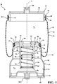
- an air suspension assembly 20 for use in a vehicle is generally shown in Fig. 1 .
- the air suspension assembly 20, as generally shown in Fig. 1 includes a top 22 disposed on a center axis A.
- the top 22 may have a cylindrical shape and an inverted U-shape in cross-section.
- a piston 24 is disposed on the center axis A spaced from the top 22.
- the piston 24 may have an inverted cup shape and an inverted U-shape in cross-section.
- a bellows 26 of an elastomeric material and having a tubular shape is disposed on the center axis A and extends annularly about the center axis A between a first end 28 and a second end 30.
- the first end 28 of the bellows 26 is secured to the top 22 and the second end 30 of the bellows 26 is secured to the piston 24 defining a first chamber 32 extending between the top 22, the piston 24, and the bellows 26.
- the bellows 26 connects the top 22 to the piston 24 forming the first chamber 32 between the top 22, the bellows 26, and the piston 24.
- the bellows 26 has an outer sleeve 34 extending from the first end 28 of the bellows 26 to an intermediate end 36 in a parallel relationship with the center axis A.
- the outer sleeve 34 may be of a tubular shape.
- the bellows 26 further includes an inner sleeve 38 extending from the intermediate end 36 of the bellows 26, in an arcuate shape, toward the center axis A and toward the first end 28 of the bellows 26, in a parallel relationship with the center axis A and the outer sleeve 34, to the second end 30 to engage the piston 24.
- the top 22 includes a plate 40 disposed on the center axis A defining an edge extending about the plate 40.
- the plate 40 may have a circular shape.
- a side wall 42 having a cylindrical shape extends perpendicularly outwardly from the edge of the plate 40 in a parallel relationship with the center axis A.
- the side wall 42 includes a plurality of protrusions 44, spaced from one another, extending outwardly from the side wall 42 and annularly about the side wall 42 in a perpendicular relationship with the center axis A to receive the first end 28 of the bellows 26.
- a first ring 46 having a circular shape is disposed on the bellows 26 at the first end 28 of the bellows 26 and extending annularly about the side wall 42 of the top 22 to secure the bellows 26 to the side walls 42 of the top 22.
- the first end 28 of the bellows 26 is sandwiched and secured by the first ring 46 between the first ring 46 and the side walls 42 of the top 22.
- the side wall 42 includes a nub 48, having a triangular shaped cross-section, disposed adjacent to the protrusions 44 and the edge of the plate 40, extending outwardly from the side wall 42 and annularly about the side wall 42 for receiving the first ring 46.
- a first bushing 50 having a cylindrical shape, is disposed on the center axis A and extending outwardly from the center axis A, away from the side wall 42, and along the center axis A for securing the air suspension assembly 20 to the vehicle.
- the piston 24 includes an upper portion 52 having a circular shape.
- the upper portion 52 has an interior surface 54 disposed in the first chamber 32 facing the top 22 and an exterior surface 56 spaced from the interior surface 54.
- a periphery 58 extends between the interior surface 54 and the exterior surface 56 and annularly about the center axis A to connect the interior surface 54 with the exterior surface 56.
- the upper portion 52 defines a bore 60, having a cylindrical shape, disposed on the center axis A and extends between the interior surface 54 and the exterior surface 56 in gas communication with the first chamber 32.
- the periphery 58 including a plurality of ridges 62, spaced from one another, and extends outwardly from the upper portion 52 in a perpendicular relationship with the center axis A to engage the second end 30 of the bellows 26.
- a second ring 64 having a circular shape is disposed at the second end 30 of the bellows 26 and extends annularly about the upper portion 52 of the piston 24 to secure the bellows 26 to the upper portion 52 of the piston 24.
- the second end 30 of the bellows 26 is sandwiched and secured by the second ring 64 between the second ring 64 and the upper portion 52 of the piston 24.
- a tab 66 is disposed adjacent to the exterior surface 56 of the upper portion 52 and extends outwardly from and annularly about the upper portion 52 to a terminal end 68 defining a shoulder disposed adjacent to the periphery 58 for receiving the second ring 64.
- the piston 24 further includes a body 70 having a bell shape attached to the upper portion 52 of the piston 24.
- the body 70 may extend from the terminal end 68 of the tab 66 and annularly about the center axis A from the terminal end 68 of the tab 66 to a proximal end 72 defining a second chamber 74 extending between the body 70 and the upper portion 52.
- a decoupler 76 is disposed in the bore 60 of the upper portion 52 and attached to the piston 24 in gas communication with the first chamber 32 and the second chamber 74.
- the decoupler 76 includes a partition member 78 extending transversely across the decoupler 76 to isolate the first chamber 32 from the second chamber 74 defining a first volume V 1 for the first chamber 32 and a second volume V 2 for the second chamber 74.
- the first volume V 1 extends between the partition member 78, the top 22, the piston 24, and the bellows 26.
- the second volume V 2 extends between the partition member 78 and the body 70 of the piston 24.
- the decoupler 76 compensates for changes in pressure in the first chamber 32 and the second chamber 74 by varying the first volume V 1 and the second volume V 2 .
- the decoupler 76 includes a cap portion 80 disposed adjacent to the interior surface 54, in the bore 60 of the upper portion 52, and defining a hole 82 disposed on the center axis A.
- the decoupler 76 also includes an extension portion 84, having a tubular shape, disposed in the second chamber 74 and extending annularly outwardly from the cap portion 80 to a distal end 86.
- the extension portion 84 defines a third chamber 88 in gas communication with the hole 82, the first chamber 32, and the second chamber 74 to receive the partition member 78.
- the cap portion 80 may include a collar 90 extending radially outwardly from the cap portion 80, in a perpendicular relationship with the center axis A, and annularly about the cap portion 80 to engage the interior surface 54 of the upper portion 52. It should be appreciated that the cap portion 80 can be secured to the upper portion 52 by any means, e.g. nuts and bolts or welding.
- the partition member 78 is a diaphragm 78 having a hexagonal shaped cross-section disposed on the center axis A and slidable in the third chamber 88 of the extension portion 84 isolating the first chamber 32 from the second chamber 74.
- the diaphragm 78 also includes a projection 92 extending radially outwardly from the diaphragm 78 and about the diaphragm 78 in a perpendicular relationship to the center axis A abutting the extension portion 84 of the decoupler 76.
- a Teflon band may be disposed annularly about the projection 92 sandwiched between the projection 92 and the extension portion 84 of the decoupler 76 for facilitating with the sliding movement of the diaphragm 78 inside the extension portion 84.
- a plurality of retaining members 94, 96 including a first retaining member 94 and a second retaining member 96 are disposed in the third chamber 88, spaced apart from one another, and sandwiching the diaphragm 78 between the retaining members 94, 96 to allow the diaphragm 78 to move between a first position and a second position.
- the first position is defined as being adjacent to the cap portion 80 and the second position is defined as adjacent to the distal end 86 of the extension portion 84 to provide a soft stiffness rate under low stroke and higher stiffness rate under larger strokes.
- the diaphragm 78 is sandwiched between the first retaining member 94 and the second retaining member 96 and in the third chamber 88 of the extension portion 84 between the first position and the second position.
- the first retaining member 94 may be a spring disposed in the third chamber 88 extending between the cap portion 80 and the diaphragm 78.
- the second retaining member 96 may also be a spring disposed in the third chamber 88 extending between the diaphragm 78 and the distal end 86 of the extension portion 84.
- the body 70 of the piston 24 may include a base 98 having a circular shape disposed on the center axis A and attached to the proximal end 72 of the body 70 to close the second chamber 74.
- a second bushing 100 extends outwardly from the base 98 opposite the first bushing 50 along the center axis A for securing the air suspension assembly 20 to the vehicle.
- the partition member 78 is a diaphragm 78 made from elastomeric material and flexible between the first position and the second position.
- the diaphragm 78 is disposed on the center axis A and secured in the third chamber 88 of the extension portion 84 isolating the first chamber 32 from the second chamber 74.
- the decoupler 76 includes a first cover 102 and a second cover 104.
- the first cover 102 having a tubular shape, is disposed between the diaphragm 78 and the cap portion 80.
- the second cover 104 having a tubular shape, is disposed spaced from the first cover 102 between the diaphragm 78 and the distal end 86 of the extension portion 84 to secure the diaphragm 78 between the first cover 102 and the second cover 104.
- the diaphragm 78 is sandwiched between the first cover 102 and the second cover 104.
- the first cover 102 includes a first disk 106 having a circular shape and an arcuate shaped cross-section with the first cover 102 bowing away from the diaphragm 78.
- the first disk 106 defines a plurality of first orifices 108, spaced from one another, in gas communication with the first chamber 32 to allow gas to flow through the first disk 106.
- the second cover 104 includes a second disk 110 having a circular shape and an arcuate shaped cross-section with the second cover 104 bowing away from the diaphragm 78 and the first disk 106.
- the second cover 104 defines a plurality of second orifices 112, spaced from one another, in gas communication with the second chamber 74 to allow gas to flow through the second disk 110.
- the body 70 of the piston 24 may include a bottom portion 114 having a T-shaped cross-section.
- the bottom portion 114 is disposed on the center axis A and attached to the proximal end 72 of the body 70 to close the second chamber 74.
- the bottom portion 114 defines a cavity 115 disposed in gas communication with the second chamber 74 expanding the second volume V 2 to between the partition member 78, the body 70 and the bottom portion 114.
- the bottom portion 114 may also include a second bushing 100 extending outwardly from the bottom portion 114 in an opposite direction of the first bushing 50, along the center axis A, for securing the air suspension assembly 20 to the vehicle.
- the partition member 78 includes a sliding guide 116 disposed in the third chamber 88 concentric to and spaced from the extension portion 84.
- the sliding guide 116 includes a sleeve 118 having a tubular shape disposed in the third chamber 88 of the extension portion 84 and extending between a first sleeve end 120 and a second sleeve end 122.
- the first sleeve end 120 is disposed adjacent to the cap portion 80.
- the second sleeve end 122 is disposed adjacent to the distal end 86 of the extension portion 84.
- the sleeve 118 defines a conduit 124 extending between the first sleeve end 120 and the second sleeve end 122.
- a rod 126 is disposed on the center axis A and in the third chamber 88.
- the rod 126 extends through the conduit 124 of the sliding guide 116 between a first rod end 128 disposed in the first chamber 32 and a second rod end 130 disposed in the second chamber 74.
- a first divider 132 of elastomeric material having a U-shaped cross-section, is disposed in the third chamber 88 extending between the first sleeve end 120 and the cap portion 80.
- a second divider 134 of elastomeric material, having an inverted U-shape cross-section, is disposed in the third chamber 88 extending between the second sleeve end 122 and the distal end 86 of the extension portion 84.
- the first rod end 128 includes a flange 136 extending radially outwardly from the first rod end 128 and perpendicular to the center axis A.
- the body 70 of the piston 24 may include a bottom portion 114, having a T-shaped cross-section, disposed on the center axis A and attached to the proximal end 72 of the body 70 to close the second chamber 74.
- the bottom portion 114 defines a cavity 115 disposed in gas communication with the second chamber 74 expanding the second volume V 2 to between the partition member 78, the body 70 and the bottom portion 114.
- the bottom portion 114 may also include a second bushing 100 extending outwardly from the bottom portion 114, in an opposite direction of the first bushing 50, along the center axis A for securing the air suspension assembly 20 to the vehicle.
- a rod guide 138 having a U-shape in cross-section, is disposed in the second chamber 74 and extends annularly about the center axis A between the bottom portion 114 and the distal end 86 of the extension portion 84.
- the rod guide 138 defines a center aperture 140 disposed on the center axis A for receiving the second rod end 130 and a plurality of pockets 142, each having a circular shape, disposed about and spaced from the center aperture 140 and for allowing gas communication between the third chamber 88 and the cavity 115.
- a fastener 144 e.g. a nut, is disposed in the cavity 115 and secured to the second rod end 130.
- a plurality of resilient members 146, 148 including a first resilient member 146 of a spring is disposed in the first chamber 32 and extending about the rod 126 between the flange 136 at the first rod end 128 and the sleeve 118.
- the plurality of resilient members 146, 148 includes a second resilient member 148 of a spring disposed in the second chamber 74 and extending about the rod 126 between the rod guide 138 and the sleeve 118 sandwiching the sleeve 118 between the first resilient member 146 and the second resilient member 148.
- the air suspension assembly 20 includes a first housing 150 having a cylindrical shape extending along a center axis A and between a first opened end 152 and a first closed end 154.
- the first housing 150 defines a first compartment 156 extending along the center axis A between the first opened end 152 and the first closed end 154.
- a top 22 having a generally cylindrical shape is disposed at the first opened end 152 of the first housing 150.
- a piston 24, having a tubular shape, is disposed in the first compartment 156 on the center axis A and adjacent to the first closed end 154 of the first housing 150.
- the first end 28 of the bellows 26 is secured to the top 22 and the second end 30 of the bellows 26 is secured to the piston 24 defining a first chamber 32 between the top 22 and the piston 24 and the first closed end 154 of the first housing 150.
- the bellows 26 includes an outer sleeve 34, having a tubular shape, extending from the first end 28 of the bellows 26 to an intermediate end 36 in a parallel relationship with the center axis A.
- An inner sleeve 38 extends from the intermediate end 36 of the bellows 26, in an arcuate shape, toward the center axis A and toward the first end 28 of the bellows 26 in a parallel relationship with the center axis A and the outer sleeve 34 to the second end 30 to engage the piston 24.
- a crimp ring 158 having a circular shape is disposed in the first chamber 32 and adjacent to the first opened end 152 of the first housing 150. The crimp ring 158 abuts the bellows 26 to secure the bellows 26 to the first housing 150 in the first compartment 156 to prevent outer sleeve 34 of the bellows 26 from collapsing in the first compartment 156.
- the top 22 includes a plate 40 and a side wall 42 having a cylindrical shape extending perpendicularly outwardly from the plate 40 parallel to the center axis A.
- the side wall 42 defines a plurality of protrusions 44, spaced from one another, extending annularly outwardly from the side wall 42 perpendicular to the center axis A spaced from one another to engage the first end 28 of the bellows 26.
- a first ring 46 having a circular shape is disposed on the bellows 26 at the first end 28 of the bellows 26 and extending annularly about the side wall 42 of the top 22 to secure the bellows 26 to the side walls 42 of the top 22.
- the piston 24 includes an upper portion 52 having a circular shape.
- the upper portion 52 includes an interior surface 54 disposed in the first chamber 32 facing the top 22 and an exterior surface 56 spaced from the interior surface 54.
- a periphery 58 extends between the interior surface 54 and the exterior surface 56 and annularly about the center axis A to connect the interior surface 54 with the exterior surface 56.
- the upper portion 52 further defines a bore 60 having a cylindrical shape disposed on the center axis A in gas communication with the first chamber 32 and extending between the interior surface 54 and the exterior surface 56.
- a second ring 64 having a circular shape is disposed on the bellows 26 at the second end 30 of the bellows 26 and extending annularly about the upper portion 52 of the piston 24 to secure the bellows 26 to the upper portion 52 of the piston 24.
- the piston 24 further includes a body 70 of tubular shape extending outwardly from the upper portion 52 and annularly about the center axis A to a proximal end 72 adjacent to the first closed end 154 defining a second chamber 74 between the body 70 and the upper portion 52.
- a second housing 160 having a cylindrical shape, spaced from the first housing 150, extends between a second opened end 162 and a second closed end 164 defining a second compartment 166 between the second opened end 162 and the second closed end 164.
- a pipe 168 having a tubular shape, defines a channel 170 extending between the top 22 and the second opened end 162 of the second housing 160 to connect the second housing 160 with the first chamber 32 and allow gas communication between the first chamber 32 and the second compartment 166 of the second housing 160.
- a decoupler 76 is disposed in the second compartment 166 and attached to the second opened end 162 of the second housing 160 and disposed in gas communication with the channel 170.
- the decoupler 76 includes a partition member 78 extending transversely across the decoupler 76 isolating the first chamber 32 from the second compartment 166 defining a first volume V 1 for the first chamber 32 and a second volume V 2 for the second compartment 166.
- the first volume V 1 extends between the partition member 78, the top 22, the piston 24, the first housing 150, and the bellows 26.
- the second volume V 2 extends between the partition member 78 and the second housing 160 of the piston 24.
- the decoupler 76 compensates for changes in pressure in the first chamber 32 and the second chamber 74 by varying the first volume V 1 and the second volume V 2 .
- the decoupler 76 includes a cap portion 80 defining a hole 82 and attached to the second opened end 162 of the second housing 160.
- An extension portion 84 having a tubular shape, is disposed in the second compartment 166 and extending annularly outwardly from the cap portion 80 to a distal end 86 defining a third chamber 88 in gas communication with the channel 170 and the first chamber 32 and the second compartment 166 to receive the partition member 78.
- the cap portion 80 includes a collar 90 extending radially outwardly from the cap portion 80, annularly about the cap portion 80, and in a perpendicular relationship with the center axis A to engage the second opened end 162 of the second housing 160. It should be appreciated that the cap portion 80 may be secured to the second housing 160 using any means, e.g. nuts and bolts or welding.
- the partition member is a diaphragm 78 having a hexagonal shaped cross-section disposed on the center axis A and slidable in the third chamber 88 of the extension portion 84 isolating the first chamber 32 from the second compartment 74.
- the diaphragm 78 also includes a projection 92 extending radially outwardly from the diaphragm 78 and about the diaphragm 78 in a perpendicular relationship to the center axis A abutting the extension portion 84 of the decoupler 76.
- a Teflon band may be disposed annularly about the projection 92 between the projection 92 and the extension portion 84 of the decoupler 76 for facilitating with the sliding movement of the diaphragm 78 inside the extension portion 84.
- a plurality of retaining members 94, 96 including a first retaining member 94 and a second retaining member 96 are disposed in the third chamber 88, spaced apart from one another, and sandwiching the diaphragm 78 between the retaining members 94, 96 to allow the diaphragm 78 to move between a first position and a second position.
- the first position is defined as being adjacent to the cap portion 80 and the second position is defined as adjacent to the distal end 86 of the extension portion 84 to provide a soft stiffness rate under low stroke and higher stiffness rate under larger strokes.
- the diaphragm 78 is sandwiched between the first retaining member 94 and the second retaining member 96 and in the third chamber 88 of the extension portion 84 between the first position and the second position.
- the first retaining member 94 may be a spring disposed in the third chamber 88 extending between the cap portion 80 and the diaphragm 78.
- the second retaining member 96 may also be a spring disposed in the third chamber 88 extending between the diaphragm 78 and the distal end 86 of the extension portion 84.
Landscapes
- Engineering & Computer Science (AREA)
- Mechanical Engineering (AREA)
- General Engineering & Computer Science (AREA)
- Physics & Mathematics (AREA)
- Fluid Mechanics (AREA)
- Fluid-Damping Devices (AREA)
- Vehicle Body Suspensions (AREA)
- Vibration Prevention Devices (AREA)
Abstract
Description
- The present invention generally relates to an air suspension assembly.
- Air suspension assemblies are often used in the axle/suspension systems of a vehicle. The air suspension assemblies act to cushion the ride, dampen vibrations and stabilize the vehicle. One such air suspension assembly is disclosed in
U.S. Patent Application 2011/0049774 which discloses the air suspension assembly including a top disposed on a center axis. A piston is disposed on the center axis spaced from the top. A bellows of an elastomeric material extending about the center axis between a first end secured to the top and a second end secured to the piston connecting the top and the piston defining a first chamber extending between the top and the piston and the bellows. The piston includes an upper portion defining a bore disposed on the center axis extending in gas communication with the first chamber. The piston includes a body extending outwardly from the upper portion and about the center axis to a proximal end defining a second chamber extending between the body and the upper portion. A decoupler is disposed in the bore of the upper portion attached to the piston and in gas communication with the first chamber and the second chamber. - The invention provides for an air suspension assembly including a decoupler wherein the decoupler includes a partition member extending transversely across the decoupler isolating the first chamber from the second chamber and defining a first volume and a second volume for changing pressure in the first chamber and the second chamber by varying the first volume and the second volume in response to a pressure applied to the air suspension assembly. The first volume for the first chamber extends between the partition member, the top, the piston, and the bellows. The second volume for the second chamber extends between the partition member and the body.
- The invention in its broadest aspect provides for an air suspension assembly that has a soft rating of stiffness under low amplitude strokes which improves the overall ride comfort for a driver and a stiff rating of stiffness under large amplitude strokes which improves handling and roll stability. Furthermore, the invention provides both cost reduction and mass reduction and energy consumption reduction by eliminating the electric valves previously used in other air suspension assemblies.
- Other advantages of the present invention will be readily appreciated, as the same becomes better understood by reference to the following detailed description when considered in connection with the accompanying drawings wherein:
-
Fig. 1 is a cross-sectional perspective view of the air suspension assembly, -
Fig. 2 is a cross-sectional perspective view of an alternative embodiment of the air suspension assembly including an alternative embodiment of the decoupler, -
Fig. 3 is an enlarged cross-sectional perspective view of the decoupler as shown inFig. 2 , -
Fig. 4 is a cross-sectional perspective view of an alternative embodiment of the air suspension assembly including an alternative embodiment of the decoupler with a sliding guide, and -
Fig. 5 is a cross-sectional perspective view of an alternative embodiment of the air suspension assembly including a first housing and a second housing. - Referring to the Figures, wherein like numerals indicate corresponding parts throughout the several views, an
air suspension assembly 20 for use in a vehicle is generally shown inFig. 1 . - The
air suspension assembly 20, as generally shown inFig. 1 , includes atop 22 disposed on a center axis A. The top 22 may have a cylindrical shape and an inverted U-shape in cross-section. Apiston 24 is disposed on the center axis A spaced from thetop 22. Thepiston 24 may have an inverted cup shape and an inverted U-shape in cross-section. Abellows 26 of an elastomeric material and having a tubular shape is disposed on the center axis A and extends annularly about the center axis A between afirst end 28 and asecond end 30. Thefirst end 28 of thebellows 26 is secured to thetop 22 and thesecond end 30 of thebellows 26 is secured to thepiston 24 defining afirst chamber 32 extending between thetop 22, thepiston 24, and thebellows 26. In other words, thebellows 26 connects thetop 22 to thepiston 24 forming thefirst chamber 32 between thetop 22, thebellows 26, and thepiston 24. - The
bellows 26 has anouter sleeve 34 extending from thefirst end 28 of thebellows 26 to anintermediate end 36 in a parallel relationship with the center axis A. Theouter sleeve 34 may be of a tubular shape. Thebellows 26 further includes aninner sleeve 38 extending from theintermediate end 36 of thebellows 26, in an arcuate shape, toward the center axis A and toward thefirst end 28 of thebellows 26, in a parallel relationship with the center axis A and theouter sleeve 34, to thesecond end 30 to engage thepiston 24. - The
top 22 includes aplate 40 disposed on the center axis A defining an edge extending about theplate 40. Theplate 40 may have a circular shape. Aside wall 42 having a cylindrical shape extends perpendicularly outwardly from the edge of theplate 40 in a parallel relationship with the center axis A. Theside wall 42 includes a plurality ofprotrusions 44, spaced from one another, extending outwardly from theside wall 42 and annularly about theside wall 42 in a perpendicular relationship with the center axis A to receive thefirst end 28 of thebellows 26. Afirst ring 46 having a circular shape is disposed on thebellows 26 at thefirst end 28 of thebellows 26 and extending annularly about theside wall 42 of thetop 22 to secure thebellows 26 to theside walls 42 of thetop 22. In other words, thefirst end 28 of thebellows 26 is sandwiched and secured by thefirst ring 46 between thefirst ring 46 and theside walls 42 of thetop 22. Theside wall 42 includes anub 48, having a triangular shaped cross-section, disposed adjacent to theprotrusions 44 and the edge of theplate 40, extending outwardly from theside wall 42 and annularly about theside wall 42 for receiving thefirst ring 46. Afirst bushing 50, having a cylindrical shape, is disposed on the center axis A and extending outwardly from the center axis A, away from theside wall 42, and along the center axis A for securing theair suspension assembly 20 to the vehicle. - The
piston 24 includes anupper portion 52 having a circular shape. Theupper portion 52 has aninterior surface 54 disposed in thefirst chamber 32 facing thetop 22 and anexterior surface 56 spaced from theinterior surface 54. Aperiphery 58 extends between theinterior surface 54 and theexterior surface 56 and annularly about the center axis A to connect theinterior surface 54 with theexterior surface 56. Theupper portion 52 defines abore 60, having a cylindrical shape, disposed on the center axis A and extends between theinterior surface 54 and theexterior surface 56 in gas communication with thefirst chamber 32. Theperiphery 58 including a plurality ofridges 62, spaced from one another, and extends outwardly from theupper portion 52 in a perpendicular relationship with the center axis A to engage thesecond end 30 of thebellows 26. Asecond ring 64 having a circular shape is disposed at thesecond end 30 of thebellows 26 and extends annularly about theupper portion 52 of thepiston 24 to secure thebellows 26 to theupper portion 52 of thepiston 24. In other words, thesecond end 30 of thebellows 26 is sandwiched and secured by thesecond ring 64 between thesecond ring 64 and theupper portion 52 of thepiston 24. Atab 66 is disposed adjacent to theexterior surface 56 of theupper portion 52 and extends outwardly from and annularly about theupper portion 52 to aterminal end 68 defining a shoulder disposed adjacent to theperiphery 58 for receiving thesecond ring 64. - The
piston 24 further includes abody 70 having a bell shape attached to theupper portion 52 of thepiston 24. Thebody 70 may extend from theterminal end 68 of thetab 66 and annularly about the center axis A from theterminal end 68 of thetab 66 to aproximal end 72 defining asecond chamber 74 extending between thebody 70 and theupper portion 52. - A
decoupler 76 is disposed in thebore 60 of theupper portion 52 and attached to thepiston 24 in gas communication with thefirst chamber 32 and thesecond chamber 74. Thedecoupler 76 includes apartition member 78 extending transversely across thedecoupler 76 to isolate thefirst chamber 32 from thesecond chamber 74 defining a first volume V1 for thefirst chamber 32 and a second volume V2 for thesecond chamber 74. The first volume V1 extends between thepartition member 78, thetop 22, thepiston 24, and thebellows 26. The second volume V2 extends between thepartition member 78 and thebody 70 of thepiston 24. In response to a pressure applied to theair suspension assembly 20, thedecoupler 76 compensates for changes in pressure in thefirst chamber 32 and thesecond chamber 74 by varying the first volume V1 and the second volume V2. - The
decoupler 76 includes acap portion 80 disposed adjacent to theinterior surface 54, in thebore 60 of theupper portion 52, and defining ahole 82 disposed on the center axis A. Thedecoupler 76 also includes anextension portion 84, having a tubular shape, disposed in thesecond chamber 74 and extending annularly outwardly from thecap portion 80 to adistal end 86. Theextension portion 84 defines athird chamber 88 in gas communication with thehole 82, thefirst chamber 32, and thesecond chamber 74 to receive thepartition member 78. Thecap portion 80 may include acollar 90 extending radially outwardly from thecap portion 80, in a perpendicular relationship with the center axis A, and annularly about thecap portion 80 to engage theinterior surface 54 of theupper portion 52. It should be appreciated that thecap portion 80 can be secured to theupper portion 52 by any means, e.g. nuts and bolts or welding. - As shown in
Fig. 1 , thepartition member 78 is adiaphragm 78 having a hexagonal shaped cross-section disposed on the center axis A and slidable in thethird chamber 88 of theextension portion 84 isolating thefirst chamber 32 from thesecond chamber 74. Thediaphragm 78 also includes aprojection 92 extending radially outwardly from thediaphragm 78 and about thediaphragm 78 in a perpendicular relationship to the center axis A abutting theextension portion 84 of thedecoupler 76. A Teflon band may be disposed annularly about theprojection 92 sandwiched between theprojection 92 and theextension portion 84 of thedecoupler 76 for facilitating with the sliding movement of thediaphragm 78 inside theextension portion 84. A plurality of retainingmembers member 94 and a second retainingmember 96 are disposed in thethird chamber 88, spaced apart from one another, and sandwiching thediaphragm 78 between the retainingmembers diaphragm 78 to move between a first position and a second position. The first position is defined as being adjacent to thecap portion 80 and the second position is defined as adjacent to thedistal end 86 of theextension portion 84 to provide a soft stiffness rate under low stroke and higher stiffness rate under larger strokes. In other words, thediaphragm 78 is sandwiched between the first retainingmember 94 and the second retainingmember 96 and in thethird chamber 88 of theextension portion 84 between the first position and the second position. It should be appreciated that the first retainingmember 94 may be a spring disposed in thethird chamber 88 extending between thecap portion 80 and thediaphragm 78. In should also be appreciated that the second retainingmember 96 may also be a spring disposed in thethird chamber 88 extending between thediaphragm 78 and thedistal end 86 of theextension portion 84. - The
body 70 of thepiston 24 may include a base 98 having a circular shape disposed on the center axis A and attached to theproximal end 72 of thebody 70 to close thesecond chamber 74. Asecond bushing 100 extends outwardly from the base 98 opposite thefirst bushing 50 along the center axis A for securing theair suspension assembly 20 to the vehicle. - Alternatively, in another embodiment of the present invention, as best shown in
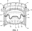
Fig. 2 , thepartition member 78 is adiaphragm 78 made from elastomeric material and flexible between the first position and the second position. Thediaphragm 78 is disposed on the center axis A and secured in thethird chamber 88 of theextension portion 84 isolating thefirst chamber 32 from thesecond chamber 74. As best shown inFig. 3 , thedecoupler 76 includes afirst cover 102 and asecond cover 104. Thefirst cover 102, having a tubular shape, is disposed between thediaphragm 78 and thecap portion 80. Thesecond cover 104, having a tubular shape, is disposed spaced from thefirst cover 102 between thediaphragm 78 and thedistal end 86 of theextension portion 84 to secure thediaphragm 78 between thefirst cover 102 and thesecond cover 104. In other words, thediaphragm 78 is sandwiched between thefirst cover 102 and thesecond cover 104. Thefirst cover 102 includes afirst disk 106 having a circular shape and an arcuate shaped cross-section with thefirst cover 102 bowing away from thediaphragm 78. Thefirst disk 106 defines a plurality offirst orifices 108, spaced from one another, in gas communication with thefirst chamber 32 to allow gas to flow through thefirst disk 106. Thesecond cover 104 includes asecond disk 110 having a circular shape and an arcuate shaped cross-section with thesecond cover 104 bowing away from thediaphragm 78 and thefirst disk 106. Thesecond cover 104 defines a plurality ofsecond orifices 112, spaced from one another, in gas communication with thesecond chamber 74 to allow gas to flow through thesecond disk 110. - The
body 70 of thepiston 24 may include abottom portion 114 having a T-shaped cross-section. Thebottom portion 114 is disposed on the center axis A and attached to theproximal end 72 of thebody 70 to close thesecond chamber 74. Thebottom portion 114 defines acavity 115 disposed in gas communication with thesecond chamber 74 expanding the second volume V2 to between thepartition member 78, thebody 70 and thebottom portion 114. Thebottom portion 114 may also include asecond bushing 100 extending outwardly from thebottom portion 114 in an opposite direction of thefirst bushing 50, along the center axis A, for securing theair suspension assembly 20 to the vehicle. - Alternatively, in another embodiment of the present invention, as best shown in
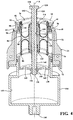
Fig. 4 , thepartition member 78 includes a slidingguide 116 disposed in thethird chamber 88 concentric to and spaced from theextension portion 84. The slidingguide 116 includes asleeve 118 having a tubular shape disposed in thethird chamber 88 of theextension portion 84 and extending between afirst sleeve end 120 and asecond sleeve end 122. Thefirst sleeve end 120 is disposed adjacent to thecap portion 80. Thesecond sleeve end 122 is disposed adjacent to thedistal end 86 of theextension portion 84. Thesleeve 118 defines aconduit 124 extending between thefirst sleeve end 120 and thesecond sleeve end 122. - A
rod 126 is disposed on the center axis A and in thethird chamber 88. Therod 126 extends through theconduit 124 of the slidingguide 116 between afirst rod end 128 disposed in thefirst chamber 32 and asecond rod end 130 disposed in thesecond chamber 74. Afirst divider 132 of elastomeric material, having a U-shaped cross-section, is disposed in thethird chamber 88 extending between thefirst sleeve end 120 and thecap portion 80. Asecond divider 134 of elastomeric material, having an inverted U-shape cross-section, is disposed in thethird chamber 88 extending between thesecond sleeve end 122 and thedistal end 86 of theextension portion 84. Thefirst rod end 128 includes aflange 136 extending radially outwardly from thefirst rod end 128 and perpendicular to the center axis A. - The
body 70 of thepiston 24 may include abottom portion 114, having a T-shaped cross-section, disposed on the center axis A and attached to theproximal end 72 of thebody 70 to close thesecond chamber 74. Thebottom portion 114 defines acavity 115 disposed in gas communication with thesecond chamber 74 expanding the second volume V2 to between thepartition member 78, thebody 70 and thebottom portion 114. Thebottom portion 114 may also include asecond bushing 100 extending outwardly from thebottom portion 114, in an opposite direction of thefirst bushing 50, along the center axis A for securing theair suspension assembly 20 to the vehicle. Arod guide 138, having a U-shape in cross-section, is disposed in thesecond chamber 74 and extends annularly about the center axis A between thebottom portion 114 and thedistal end 86 of theextension portion 84. Therod guide 138 defines acenter aperture 140 disposed on the center axis A for receiving thesecond rod end 130 and a plurality ofpockets 142, each having a circular shape, disposed about and spaced from thecenter aperture 140 and for allowing gas communication between thethird chamber 88 and thecavity 115. Afastener 144, e.g. a nut, is disposed in thecavity 115 and secured to thesecond rod end 130. A plurality ofresilient members resilient member 146 of a spring is disposed in thefirst chamber 32 and extending about therod 126 between theflange 136 at thefirst rod end 128 and thesleeve 118. The plurality ofresilient members resilient member 148 of a spring disposed in thesecond chamber 74 and extending about therod 126 between therod guide 138 and thesleeve 118 sandwiching thesleeve 118 between the firstresilient member 146 and the secondresilient member 148. - Alternatively, in another embodiment of the present invention, as generally shown in
Fig. 5 , theair suspension assembly 20 includes afirst housing 150 having a cylindrical shape extending along a center axis A and between a first openedend 152 and a firstclosed end 154. Thefirst housing 150 defines afirst compartment 156 extending along the center axis A between the first openedend 152 and the firstclosed end 154. A top 22 having a generally cylindrical shape is disposed at the first openedend 152 of thefirst housing 150. Apiston 24, having a tubular shape, is disposed in thefirst compartment 156 on the center axis A and adjacent to the firstclosed end 154 of thefirst housing 150. A bellows 26, made from an elastomeric material and having a tubular shape, is disposed in thefirst compartment 156 on the center axis A and extending annularly about the center axis A between afirst end 28 and asecond end 30. Thefirst end 28 of thebellows 26 is secured to the top 22 and thesecond end 30 of thebellows 26 is secured to thepiston 24 defining afirst chamber 32 between the top 22 and thepiston 24 and the firstclosed end 154 of thefirst housing 150. The bellows 26 includes anouter sleeve 34, having a tubular shape, extending from thefirst end 28 of thebellows 26 to anintermediate end 36 in a parallel relationship with the center axis A. Aninner sleeve 38 extends from theintermediate end 36 of thebellows 26, in an arcuate shape, toward the center axis A and toward thefirst end 28 of thebellows 26 in a parallel relationship with the center axis A and theouter sleeve 34 to thesecond end 30 to engage thepiston 24. Acrimp ring 158 having a circular shape is disposed in thefirst chamber 32 and adjacent to the first openedend 152 of thefirst housing 150. Thecrimp ring 158 abuts thebellows 26 to secure thebellows 26 to thefirst housing 150 in thefirst compartment 156 to preventouter sleeve 34 of thebellows 26 from collapsing in thefirst compartment 156. - The top 22 includes a
plate 40 and aside wall 42 having a cylindrical shape extending perpendicularly outwardly from theplate 40 parallel to the center axis A. Theside wall 42 defines a plurality ofprotrusions 44, spaced from one another, extending annularly outwardly from theside wall 42 perpendicular to the center axis A spaced from one another to engage thefirst end 28 of thebellows 26. Afirst ring 46 having a circular shape is disposed on thebellows 26 at thefirst end 28 of thebellows 26 and extending annularly about theside wall 42 of the top 22 to secure thebellows 26 to theside walls 42 of the top 22. - The
piston 24 includes anupper portion 52 having a circular shape. Theupper portion 52 includes aninterior surface 54 disposed in thefirst chamber 32 facing the top 22 and anexterior surface 56 spaced from theinterior surface 54. Aperiphery 58 extends between theinterior surface 54 and theexterior surface 56 and annularly about the center axis A to connect theinterior surface 54 with theexterior surface 56. Theupper portion 52 further defines abore 60 having a cylindrical shape disposed on the center axis A in gas communication with thefirst chamber 32 and extending between theinterior surface 54 and theexterior surface 56. Asecond ring 64 having a circular shape is disposed on thebellows 26 at thesecond end 30 of thebellows 26 and extending annularly about theupper portion 52 of thepiston 24 to secure thebellows 26 to theupper portion 52 of thepiston 24. Thepiston 24 further includes abody 70 of tubular shape extending outwardly from theupper portion 52 and annularly about the center axis A to aproximal end 72 adjacent to the firstclosed end 154 defining asecond chamber 74 between thebody 70 and theupper portion 52. - A
second housing 160 having a cylindrical shape, spaced from thefirst housing 150, extends between a second openedend 162 and a secondclosed end 164 defining asecond compartment 166 between the second openedend 162 and the secondclosed end 164. Apipe 168, having a tubular shape, defines achannel 170 extending between the top 22 and the second openedend 162 of thesecond housing 160 to connect thesecond housing 160 with thefirst chamber 32 and allow gas communication between thefirst chamber 32 and thesecond compartment 166 of thesecond housing 160. - A
decoupler 76 is disposed in thesecond compartment 166 and attached to the second openedend 162 of thesecond housing 160 and disposed in gas communication with thechannel 170. Thedecoupler 76 includes apartition member 78 extending transversely across thedecoupler 76 isolating thefirst chamber 32 from thesecond compartment 166 defining a first volume V1 for thefirst chamber 32 and a second volume V2 for thesecond compartment 166. The first volume V1 extends between thepartition member 78, the top 22, thepiston 24, thefirst housing 150, and thebellows 26. The second volume V2 extends between thepartition member 78 and thesecond housing 160 of thepiston 24. In response to a pressure applied to theair suspension assembly 20, thedecoupler 76 compensates for changes in pressure in thefirst chamber 32 and thesecond chamber 74 by varying the first volume V1 and the second volume V2. - The
decoupler 76 includes acap portion 80 defining ahole 82 and attached to the second openedend 162 of thesecond housing 160. Anextension portion 84, having a tubular shape, is disposed in thesecond compartment 166 and extending annularly outwardly from thecap portion 80 to adistal end 86 defining athird chamber 88 in gas communication with thechannel 170 and thefirst chamber 32 and thesecond compartment 166 to receive thepartition member 78. Thecap portion 80 includes acollar 90 extending radially outwardly from thecap portion 80, annularly about thecap portion 80, and in a perpendicular relationship with the center axis A to engage the second openedend 162 of thesecond housing 160. It should be appreciated that thecap portion 80 may be secured to thesecond housing 160 using any means, e.g. nuts and bolts or welding. - The partition member is a
diaphragm 78 having a hexagonal shaped cross-section disposed on the center axis A and slidable in thethird chamber 88 of theextension portion 84 isolating thefirst chamber 32 from thesecond compartment 74. Thediaphragm 78 also includes aprojection 92 extending radially outwardly from thediaphragm 78 and about thediaphragm 78 in a perpendicular relationship to the center axis A abutting theextension portion 84 of thedecoupler 76. A Teflon band may be disposed annularly about theprojection 92 between theprojection 92 and theextension portion 84 of thedecoupler 76 for facilitating with the sliding movement of thediaphragm 78 inside theextension portion 84. A plurality of retainingmembers member 94 and a second retainingmember 96 are disposed in thethird chamber 88, spaced apart from one another, and sandwiching thediaphragm 78 between the retainingmembers diaphragm 78 to move between a first position and a second position. The first position is defined as being adjacent to thecap portion 80 and the second position is defined as adjacent to thedistal end 86 of theextension portion 84 to provide a soft stiffness rate under low stroke and higher stiffness rate under larger strokes. In other words, thediaphragm 78 is sandwiched between the first retainingmember 94 and the second retainingmember 96 and in thethird chamber 88 of theextension portion 84 between the first position and the second position. It should be appreciated that the first retainingmember 94 may be a spring disposed in thethird chamber 88 extending between thecap portion 80 and thediaphragm 78. In should also be appreciated that the second retainingmember 96 may also be a spring disposed in thethird chamber 88 extending between thediaphragm 78 and thedistal end 86 of theextension portion 84. - Obviously, many modifications and variations of the present invention are possible in light of the above teachings and may be practiced otherwise than as specifically described while within the scope of the appended claims. The use of the word "said" in the apparatus claims refers to an antecedent that is a positive recitation meant to be included in the coverage of the claims whereas the word "the" precedes a word not meant to be included in the coverage of the claims. In addition, the reference numerals in the claims are merely for convenience and are not to be read in any way as limiting.
Claims (15)
- An air suspension assembly comprising:a top disposed on a center axis,a piston disposed on said center axis spaced from said top,a bellows of an elastomeric material extending about said center axis between a first end secured to said top and a second end secured to said piston connecting said top and said piston defining a first chamber extending between said top and said piston and said bellows,said piston including an upper portion defining a bore disposed on said center axis extending in gas communication with said first chamber,said piston further including a body extending outwardly from said upper portion and about said center axis to a proximal end defining a second chamber extending between said body and said upper portion,a decoupler disposed in said bore of said upper portion attached to said piston and disposed in gas communication with said first chamber and said second chamber, andsaid decoupler including a partition member extending transversely across said decoupler isolating said first chamber from said second chamber and defining a first volume for said first chamber between said partition member and said top and said piston and said bellows and a second volume for said second chamber between said partition member and said body for changing pressure in said first chamber and said second chamber by varying said first volume and said second volume in response to a pressure applied to the air suspension assembly.
- The air suspension assembly as set forth in Claim 1 wherein said decoupler further includes a cap portion defining a hole disposed on said center axis and in said bore and an extension portion of tubular shape disposed in said second chamber and extending annularly outwardly from said cap portion to a distal end defining a third chamber in gas communication with said hole and said first chamber and said second chamber to receive said partition member.
- The air suspension assembly as set forth in Claim 2 wherein said cap portion includes a collar extending radially outwardly from said cap portion perpendicular to said center axis and annularly about said cap portion to engage said upper portion.
- The air suspension assembly as set forth in Claim 2 or 3 wherein said partition member is a diaphragm having a hexagonal shaped cross-section disposed on said center axis and slidable in said third chamber of said extension portion isolating said first chamber from said second chamber.
- The air suspension assembly as set forth in Claim 4 wherein said diaphragm includes a projection extending radially outwardly from said diaphragm and about said diaphragm perpendicular to said center axis abutting said extension portion of said decoupler; and said decoupler includes a plurality of retaining members including a first retaining member of a spring disposed between said diaphragm and said cap portion and a second retaining member of a spring spaced from said first retaining member and disposed between said diaphragm and said distal end of said extension portion to secure said diaphragm between said first retaining member and said second retaining member allowing the diaphragm to move between a first position adjacent to said cap portion and a second position adjacent to said distal end of said extension portion.
- The air suspension assembly as set forth in any one of Claims 1 to 5 wherein said body of said piston includes a base of circular shape disposed on said center axis and attached to said proximal end of said body to close said second chamber and said base including a second bushing extending outwardly from said base along said center axis for securing the air suspension assembly to a vehicle.
- The air suspension assembly as set forth in Claim 2 wherein said partition member is a diaphragm of elastomeric material disposed on said center axis and secured in said third chamber of said extension portion isolating said first chamber from said second chamber and flexible between a first position adjacent to said cap portion and a second position adjacent to said distal end of said extension portion.
- The air suspension assembly as set forth in Claim 7 wherein said decoupler includes a first cover of tubular shape disposed between said diaphragm and said cap portion and a second cover of tubular shape spaced from said first cover and disposed between said diaphragm and said distal end of said extension portion to secure said diaphragm between said first cover and said second cover, wherein said first cover includes a first disk of circular shape and having an arcuate shaped cross-section bowing away from said diaphragm and defining a plurality of first orifices allowing fluid to flow through said first disk, and said second cover includes a second disk of circular shape and having an arcuate shaped cross-section bowing away from said diaphragm and said first disk and defining a plurality of second orifices allowing fluid to flow through said second disk.
- The air suspension assembly as set forth in Claim 7 or 8 wherein said body of said piston includes a bottom portion having a T-shaped cross-section disposed on said center axis attached to said proximal end of said body to close said second chamber and defining a cavity disposed in gas communication with said second chamber with said bottom portion expanding said second volume to between said partition member and said body and said bottom portion.
- The air suspension assembly as set forth in Claim 2 wherein said partition member includes a sliding guide disposed in said third chamber concentric to and spaced from said extension portion,
said sliding guide including a sleeve of tubular shape disposed in said third chamber of said extension portion and extending between a first sleeve end adjacent to said cap portion and a second sleeve end adjacent to said distal end of said extension portion and defining a conduit extending between said first sleeve end and said second sleeve end,
a rod disposed said third chamber on said center axis extending through said conduit of said sliding guide between a first rod end disposed in said first chamber and a second rod end disposed in said second chamber,
said sliding guide including a first divider of elastomeric material having a U-shaped cross-section disposed in said third chamber extending between said first sleeve end and said cap portion, and
said sliding guide including a second divider of elastomeric material having a U-shaped cross-section disposed in said third chamber extending between said second sleeve end and said distal end of said extension portion. - The air suspension assembly as set forth in Claim 10 wherein said first rod end includes a flange extending radially outwardly from said first rod end and perpendicular to said center axis; and said body of said piston includes a bottom portion having a T-shaped cross-section disposed on said center axis attached to said proximal end of said body to close said second chamber and defining a cavity disposed in gas communication with said second chamber expanding said second volume to between said partition member and said body and said bottom portion.
- The air suspension assembly as set forth in Claim 11 wherein said sliding guide includes a rod guide of U-shape in cross-section disposed in said second chamber and extending annularly about said center axis between said bottom portion and said distal end of said extension portion and defining a center aperture disposed on said center axis for receiving said second rod end, and said rod guide further defining a plurality of pockets of circular shape disposed about and spaced from said center aperture and for allowing gas communication between said third chamber and said cavity,
wherein the air suspension assembly further includes a fastener disposed in said cavity and secured to said second rod end; and a first resilient member of a spring disposed in said first chamber and extending about said rod between said flange at said first rod end and said sleeve and a second resilient member of a spring disposed in said second chamber and extending about said rod between said rod guide and said sleeve sandwiching said sleeve between said first resilient member and said second resilient member. - An air suspension assembly comprising:a first housing extending along a center axis between a first opened end and a first closed end defining a first compartment between said first opened end and said first closed end,a top disposed adjacent to said first opened end of said first housing,a piston disposed in said first compartment on said center axis and adjacent to said first closed end of said first housing,a bellows of an elastomeric material disposed in said first compartment extending about said center axis between a first end secured to said top and a second end secured to said piston defining a first chamber between said top and said piston and said first closed end of said first housing,said piston including an upper portion defining a bore disposed on said center axis in gas communication with said first chamber,said piston further including a body extending outwardly from said upper portion and annularly about said center axis to a proximal end adjacent to said first closed end defining a second chamber between said body and said upper portion,a second housing of cylindrical shape spaced from said first housing extending between a second opened end and a second closed end defining a second compartment between said second opened end and said second closed end,a pipe of tubular shape defining a channel extending between said top and said second opened end of said second housing allowing gas communication between said first chamber and said second compartments,a decoupler disposed in said second compartment and attached to said second opened end of said second housing and disposed in gas communication with said channel, andsaid decoupler including a partition member extending transversely across said decoupler isolating said first chamber from said second compartment and defining a first volume for said first chamber between said partition member and said top and said piston and said bellows and a second volume for said second compartment between said partition member and said second housing for changing pressure in said first chamber and said second compartment by varying said first volume and said second volume in response to a pressure applied to the air suspension assembly.
- The air suspension assembly as set forth in Claim 13 wherein said decoupler further includes a cap portion defining a hole and attached to said second opened end of said second housing and an extension portion of tubular shape disposed in said second compartment and extending annularly outwardly from said cap portion to a distal end defining a third chamber in gas communication with said channel and said first chamber and said second compartment to receive said partition member.
- The air suspension assembly as set forth in Claim 14 wherein said cap portion includes a collar extending radially outwardly from said cap portion and perpendicular to said center axis and annularly about said cap portion to engage said second opened end of said second housing; said partition member is a diaphragm having a hexagonal shaped cross-section disposed on said center axis and slidable in said third chamber of said extension portion isolating said first chamber from said second compartment; said diaphragm includes a projection extending radially outwardly from said diaphragm and about said diaphragm perpendicular to said center axis abutting said extension portion of said decoupler; and said decoupler includes a plurality of retaining members including a first retaining member of a spring disposed between said diaphragm and said cap portion and a second retaining member of a spring spaced from said first retaining member and disposed between said diaphragm and said distal end of said extension portion to secure said diaphragm between said first retaining member and said second retaining member allowing the diaphragm to move between a first position adjacent to said cap portion and a second position adjacent to said distal end of said extension portion; and/or the air suspension assembly further includes a crimp ring of circular shape disposed in said first chamber and adjacent to said first opened end of said first housing and abutting said bellows to secure said bellows to said first housing in said first compartment.
Priority Applications (1)
| Application Number | Priority Date | Filing Date | Title |
|---|---|---|---|
| PL17001578T PL3299193T3 (en) | 2016-09-22 | 2017-09-22 | An air suspension assembly |
Applications Claiming Priority (2)
| Application Number | Priority Date | Filing Date | Title |
|---|---|---|---|
| US201662398131P | 2016-09-22 | 2016-09-22 | |
| US15/671,135 US10525785B2 (en) | 2016-09-22 | 2017-08-07 | Air suspension assembly |
Publications (3)
| Publication Number | Publication Date |
|---|---|
| EP3299193A2 true EP3299193A2 (en) | 2018-03-28 |
| EP3299193A3 EP3299193A3 (en) | 2018-06-13 |
| EP3299193B1 EP3299193B1 (en) | 2020-04-15 |
Family
ID=59968880
Family Applications (1)
| Application Number | Title | Priority Date | Filing Date |
|---|---|---|---|
| EP17001578.8A Active EP3299193B1 (en) | 2016-09-22 | 2017-09-22 | An air suspension assembly |
Country Status (6)
| Country | Link |
|---|---|
| US (1) | US10525785B2 (en) |
| EP (1) | EP3299193B1 (en) |
| JP (1) | JP6486432B2 (en) |
| CN (1) | CN107512145B (en) |
| ES (1) | ES2802537T3 (en) |
| PL (1) | PL3299193T3 (en) |
Cited By (1)
| Publication number | Priority date | Publication date | Assignee | Title |
|---|---|---|---|---|
| EP4006376A1 (en) * | 2020-11-25 | 2022-06-01 | BeijingWest Industries Co. Ltd. | A gas cup for a damper assembly and a damper assembly |
Families Citing this family (12)
| Publication number | Priority date | Publication date | Assignee | Title |
|---|---|---|---|---|
| CN108839529B (en) * | 2018-07-04 | 2019-03-26 | 湖南工学院 | A kind of active variable volume air suspension and its control method |
| CN108749506B (en) * | 2018-07-04 | 2019-03-26 | 湖南工学院 | A kind of interconnection type variable volume air suspension and its control method |
| DE112020001936T5 (en) | 2019-04-15 | 2022-01-13 | ILJIN USA Corporation | AIR SPRINGS AND METHOD OF MAKING SAME |
| US11459002B2 (en) * | 2019-09-18 | 2022-10-04 | Transportation Ip Holdings, Llc | Methods and systems for dynamic weight management |
| CN112879485B (en) * | 2020-04-27 | 2022-11-25 | 北京京西重工有限公司 | Air suspension assembly and bellows for an air suspension assembly |
| US12442429B2 (en) | 2021-05-12 | 2025-10-14 | Vorsprung Technologies, Ltd. | High dynamic range suspension apparatus with selective fluid pressure communication |
| CN113090697B (en) * | 2021-05-14 | 2025-05-06 | 浙江孔辉汽车科技股份有限公司 | An air spring |
| CN113173046B (en) * | 2021-05-18 | 2022-10-28 | 贵州詹阳动力重工有限公司 | Horizontal adjusting device and wheeled multi-purpose machineshop car |
| CN117957128A (en) * | 2021-08-27 | 2024-04-30 | 亨德里克森美国有限责任公司 | Damped air springs for heavy vehicle axle/suspension systems |
| CN114033826B (en) * | 2021-12-14 | 2025-08-26 | 浙江孔辉汽车科技股份有限公司 | Air springs |
| CN114962522A (en) * | 2022-04-11 | 2022-08-30 | 中国第一汽车股份有限公司 | Variable-rigidity air spring |
| US12291072B2 (en) * | 2022-08-30 | 2025-05-06 | DRiV Automotive Inc. | Air-spring assembly |
Citations (1)
| Publication number | Priority date | Publication date | Assignee | Title |
|---|---|---|---|---|
| US20110049774A1 (en) | 2008-04-08 | 2011-03-03 | Thomas Naber | Shock absorber having compressible fluid |
Family Cites Families (33)
| Publication number | Priority date | Publication date | Assignee | Title |
|---|---|---|---|---|
| NL238562A (en) | 1959-04-24 | |||
| JPS571843A (en) | 1980-06-04 | 1982-01-07 | Hitachi Ltd | Air spring |
| JPH03177633A (en) | 1989-09-29 | 1991-08-01 | Bridgestone Corp | Air spring |
| DE4124516A1 (en) | 1990-09-07 | 1992-03-26 | Iveco Magirus | MULTI-STAGE AIR SPRING, IN PARTICULAR FOR AN AIR SPRING VEHICLE AXLE OF A COMMERCIAL VEHICLE |
| JPH0577638U (en) | 1992-03-24 | 1993-10-22 | 日産ディーゼル工業株式会社 | Air spring device |
| JPH0577639U (en) | 1992-03-25 | 1993-10-22 | 日産ディーゼル工業株式会社 | Air spring device |
| DE4300669C1 (en) | 1993-01-13 | 1994-08-18 | Continental Ag | Pneumatic spring with elastomeric pneumatic-spring bellows and an additional volume |
| JP2881546B2 (en) | 1994-04-14 | 1999-04-12 | 日野自動車工業株式会社 | Air spring device |
| SE513416C2 (en) | 1997-12-18 | 2000-09-11 | Volvo Lastvagnar Ab | Procedure for raising and lowering a vehicle chassis |
| US6374966B1 (en) | 1998-12-04 | 2002-04-23 | Lillbacka Jetair Oy | Shock absorber assembly |
| US20040026836A1 (en) | 2002-08-07 | 2004-02-12 | Brookes Graham R. | Vehicle suspension system |
| DE102004059764C5 (en) | 2004-12-11 | 2013-06-06 | Continental Teves Ag & Co. Ohg | Air spring and damper unit |
| JP2009154547A (en) | 2007-12-25 | 2009-07-16 | Nissan Diesel Motor Co Ltd | Air spring type suspension and spring constant switch control method |
| US8403115B2 (en) | 2008-01-11 | 2013-03-26 | Penske Racing Shocks | Dual rate gas spring shock absorber |
| JP5307486B2 (en) | 2008-09-16 | 2013-10-02 | 株式会社ブリヂストン | Air spring |
| DE102009011414A1 (en) | 2009-03-03 | 2010-09-09 | Zf Friedrichshafen Ag | Spring-damper unit for chassis frame of passenger car, has damping medium chambered in form-variable element and working together directly or indirectly with damping element that is arranged in separate container |
| DE102009015939A1 (en) | 2009-04-02 | 2010-12-16 | Knorr-Bremse Systeme für Nutzfahrzeuge GmbH | Damper compressor and method for generating compressed air by damping a relative movement between an axle and a chassis of a vehicle |
| US9011414B2 (en) * | 2009-04-04 | 2015-04-21 | Adam Judd Hansen | Systems and methods for hernia repair |
| DE102009002617A1 (en) | 2009-04-24 | 2010-10-28 | Zf Friedrichshafen Ag | Air spring damper |
| DE102010014559A1 (en) | 2010-04-10 | 2011-10-13 | Audi Ag | air spring |
| CN103080595B (en) | 2010-09-10 | 2015-11-25 | 亨德里克森美国有限责任公司 | Air springs with damping features for heavy-duty vehicles |
| DE102010040980B4 (en) | 2010-09-17 | 2014-04-03 | Saf-Holland Gmbh | air spring |
| US9630469B2 (en) | 2010-10-18 | 2017-04-25 | Firestone Industrial Products Company, Llc | Gas spring and gas damper assembly and method |
| DE102011086909A1 (en) | 2011-02-08 | 2012-08-09 | Continental Teves Ag & Co. Ohg | Air strut for a vehicle |
| DE102011050103A1 (en) | 2011-05-04 | 2012-11-08 | Contitech Luftfedersysteme Gmbh | Rolling piston for a Luftfederrollbalg |
| DE102011112130A1 (en) | 2011-09-01 | 2013-03-07 | Audi Ag | Air spring device for a motor vehicle |
| BR112014007999A2 (en) | 2011-10-05 | 2017-04-11 | Firestone Ind Products Co Llc | gas spring and gas damper assembly and method |
| DE102011115986A1 (en) | 2011-10-14 | 2013-04-18 | Audi Ag | Air spring for motor car, has fluid-tight limiting separating element whose limit pressure is greater than prevailing working pressure of air spring space at selected operating point of air spring |
| WO2013075036A1 (en) | 2011-11-16 | 2013-05-23 | Firestone Industrial Products Company, Llc | Axial clutch assembly as well as gas spring and gas damper assembly and method including same |
| DE102012103358A1 (en) | 2012-04-18 | 2013-10-24 | Contitech Luftfedersysteme Gmbh | Rolling piston for a Luftfederrollbalg |
| US9259985B2 (en) | 2012-09-07 | 2016-02-16 | Firestone Industrial Products Company, Llc | Gas spring and damper assemblies and methods |
| US9951837B2 (en) | 2013-05-22 | 2018-04-24 | Firestone Industrial Products Company, Llc | End member and gas spring assembly including same |
| DE102013107826A1 (en) * | 2013-07-23 | 2015-01-29 | Dr. Ing. H.C. F. Porsche Aktiengesellschaft | Air spring for a motor vehicle |
-
2017
- 2017-08-07 US US15/671,135 patent/US10525785B2/en active Active
- 2017-08-15 CN CN201710696168.4A patent/CN107512145B/en active Active
- 2017-09-15 JP JP2017177213A patent/JP6486432B2/en active Active
- 2017-09-22 EP EP17001578.8A patent/EP3299193B1/en active Active
- 2017-09-22 ES ES17001578T patent/ES2802537T3/en active Active
- 2017-09-22 PL PL17001578T patent/PL3299193T3/en unknown
Patent Citations (1)
| Publication number | Priority date | Publication date | Assignee | Title |
|---|---|---|---|---|
| US20110049774A1 (en) | 2008-04-08 | 2011-03-03 | Thomas Naber | Shock absorber having compressible fluid |
Cited By (2)
| Publication number | Priority date | Publication date | Assignee | Title |
|---|---|---|---|---|
| EP4006376A1 (en) * | 2020-11-25 | 2022-06-01 | BeijingWest Industries Co. Ltd. | A gas cup for a damper assembly and a damper assembly |
| US11668364B2 (en) | 2020-11-25 | 2023-06-06 | Beijingwest Industries Co., Ltd | Gas cup for a damper assembly and a damper assembly |
Also Published As
| Publication number | Publication date |
|---|---|
| JP6486432B2 (en) | 2019-03-20 |
| US10525785B2 (en) | 2020-01-07 |
| CN107512145A (en) | 2017-12-26 |
| EP3299193A3 (en) | 2018-06-13 |
| EP3299193B1 (en) | 2020-04-15 |
| US20180079274A1 (en) | 2018-03-22 |
| ES2802537T3 (en) | 2021-01-20 |
| JP2018048736A (en) | 2018-03-29 |
| CN107512145B (en) | 2019-06-28 |
| PL3299193T3 (en) | 2020-10-19 |
Similar Documents
| Publication | Publication Date | Title |
|---|---|---|
| EP3299193A2 (en) | An air suspension assembly | |
| EP0132404A2 (en) | Fluid-sealed engine mounting | |
| EP3578848A1 (en) | Hydraulic damper with a compression stop assembly | |
| EP3343064B1 (en) | Vertical decoupler for a hydraulic mount | |
| CN106122358B (en) | Active engine mount | |
| JPH03234938A (en) | Vibration damping equipment | |
| US20160356336A1 (en) | Bolt through hydraulic mount with and without a decoupler | |
| US8177201B2 (en) | Very high damping mount with bolt-through construction | |
| EP3537002A1 (en) | Dual ride damper assembly | |
| US11156263B2 (en) | MR mount with a dual hardness rubber decoupler | |
| US10899215B2 (en) | Hydraulic mount apparatus | |
| MX2014012637A (en) | Guide member for use in a valve actuator assembly. | |
| US6695105B2 (en) | Hydraulic shock absorber | |
| US20190154105A1 (en) | Fluid-filled vibration-damping device | |
| US10927922B2 (en) | Hydraulic mount | |
| EP3620683B1 (en) | Mr mount apparatus using a polymeric sheet decoupler | |
| CN108131390A (en) | Water resilient bearing | |
| CN114321251B (en) | Air spring assembly and automobile | |
| JP2005106150A (en) | Anti-vibration mount assembly | |
| CN114321252B (en) | Air spring components and automobiles | |
| US11009097B2 (en) | Hydraulic mount having fluid-track | |
| JP4865761B2 (en) | Suspension support | |
| JP6989216B2 (en) | Anti-vibration device | |
| JP2006226469A (en) | Suspended fluid filled anti-vibration mount | |
| JP2016114145A (en) | Vibration control device |
Legal Events
| Date | Code | Title | Description |
|---|---|---|---|
| PUAI | Public reference made under article 153(3) epc to a published international application that has entered the european phase |
Free format text: ORIGINAL CODE: 0009012 |
|
| STAA | Information on the status of an ep patent application or granted ep patent |
Free format text: STATUS: THE APPLICATION HAS BEEN PUBLISHED |
|
| AK | Designated contracting states |
Kind code of ref document: A2 Designated state(s): AL AT BE BG CH CY CZ DE DK EE ES FI FR GB GR HR HU IE IS IT LI LT LU LV MC MK MT NL NO PL PT RO RS SE SI SK SM TR |
|
| AX | Request for extension of the european patent |
Extension state: BA ME |
|
| RIN1 | Information on inventor provided before grant (corrected) |
Inventor name: ROSE, IAIN Inventor name: FANELLI, DOMINIQUE Inventor name: MARCHAND, JOCELYN |
|
| PUAL | Search report despatched |
Free format text: ORIGINAL CODE: 0009013 |
|
| AK | Designated contracting states |
Kind code of ref document: A3 Designated state(s): AL AT BE BG CH CY CZ DE DK EE ES FI FR GB GR HR HU IE IS IT LI LT LU LV MC MK MT NL NO PL PT RO RS SE SI SK SM TR |
|
| AX | Request for extension of the european patent |
Extension state: BA ME |
|
| RIC1 | Information provided on ipc code assigned before grant |
Ipc: B60G 11/27 20060101AFI20180508BHEP Ipc: F16F 9/512 20060101ALI20180508BHEP Ipc: B60G 17/048 20060101ALI20180508BHEP Ipc: B60G 17/052 20060101ALI20180508BHEP Ipc: B60G 11/58 20060101ALI20180508BHEP Ipc: F16F 9/04 20060101ALI20180508BHEP Ipc: F16F 9/05 20060101ALI20180508BHEP |
|
| STAA | Information on the status of an ep patent application or granted ep patent |
Free format text: STATUS: REQUEST FOR EXAMINATION WAS MADE |
|
| 17P | Request for examination filed |
Effective date: 20181213 |
|
| RBV | Designated contracting states (corrected) |
Designated state(s): AL AT BE BG CH CY CZ DE DK EE ES FI FR GB GR HR HU IE IS IT LI LT LU LV MC MK MT NL NO PL PT RO RS SE SI SK SM TR |
|
| GRAP | Despatch of communication of intention to grant a patent |
Free format text: ORIGINAL CODE: EPIDOSNIGR1 |
|
| STAA | Information on the status of an ep patent application or granted ep patent |
Free format text: STATUS: GRANT OF PATENT IS INTENDED |
|
| INTG | Intention to grant announced |
Effective date: 20191029 |
|
| RAP1 | Party data changed (applicant data changed or rights of an application transferred) |
Owner name: BEIJINGWEST INDUSTRIES CO., LTD. |
|
| GRAS | Grant fee paid |
Free format text: ORIGINAL CODE: EPIDOSNIGR3 |
|
| GRAA | (expected) grant |
Free format text: ORIGINAL CODE: 0009210 |
|
| STAA | Information on the status of an ep patent application or granted ep patent |
Free format text: STATUS: THE PATENT HAS BEEN GRANTED |
|
| AK | Designated contracting states |
Kind code of ref document: B1 Designated state(s): AL AT BE BG CH CY CZ DE DK EE ES FI FR GB GR HR HU IE IS IT LI LT LU LV MC MK MT NL NO PL PT RO RS SE SI SK SM TR |
|
| REG | Reference to a national code |
Ref country code: CH Ref legal event code: EP |
|
| REG | Reference to a national code |
Ref country code: DE Ref legal event code: R096 Ref document number: 602017014601 Country of ref document: DE |
|
| REG | Reference to a national code |
Ref country code: IE Ref legal event code: FG4D |
|
| REG | Reference to a national code |
Ref country code: AT Ref legal event code: REF Ref document number: 1256847 Country of ref document: AT Kind code of ref document: T Effective date: 20200515 |
|
| REG | Reference to a national code |
Ref country code: RO Ref legal event code: EPE |
|
| REG | Reference to a national code |
Ref country code: NL Ref legal event code: MP Effective date: 20200415 |
|
| REG | Reference to a national code |
Ref country code: LT Ref legal event code: MG4D |
|
| PG25 | Lapsed in a contracting state [announced via postgrant information from national office to epo] |
Ref country code: LT Free format text: LAPSE BECAUSE OF FAILURE TO SUBMIT A TRANSLATION OF THE DESCRIPTION OR TO PAY THE FEE WITHIN THE PRESCRIBED TIME-LIMIT Effective date: 20200415 Ref country code: PT Free format text: LAPSE BECAUSE OF FAILURE TO SUBMIT A TRANSLATION OF THE DESCRIPTION OR TO PAY THE FEE WITHIN THE PRESCRIBED TIME-LIMIT Effective date: 20200817 Ref country code: NL Free format text: LAPSE BECAUSE OF FAILURE TO SUBMIT A TRANSLATION OF THE DESCRIPTION OR TO PAY THE FEE WITHIN THE PRESCRIBED TIME-LIMIT Effective date: 20200415 Ref country code: FI Free format text: LAPSE BECAUSE OF FAILURE TO SUBMIT A TRANSLATION OF THE DESCRIPTION OR TO PAY THE FEE WITHIN THE PRESCRIBED TIME-LIMIT Effective date: 20200415 Ref country code: NO Free format text: LAPSE BECAUSE OF FAILURE TO SUBMIT A TRANSLATION OF THE DESCRIPTION OR TO PAY THE FEE WITHIN THE PRESCRIBED TIME-LIMIT Effective date: 20200715 Ref country code: GR Free format text: LAPSE BECAUSE OF FAILURE TO SUBMIT A TRANSLATION OF THE DESCRIPTION OR TO PAY THE FEE WITHIN THE PRESCRIBED TIME-LIMIT Effective date: 20200716 Ref country code: SE Free format text: LAPSE BECAUSE OF FAILURE TO SUBMIT A TRANSLATION OF THE DESCRIPTION OR TO PAY THE FEE WITHIN THE PRESCRIBED TIME-LIMIT Effective date: 20200415 Ref country code: IS Free format text: LAPSE BECAUSE OF FAILURE TO SUBMIT A TRANSLATION OF THE DESCRIPTION OR TO PAY THE FEE WITHIN THE PRESCRIBED TIME-LIMIT Effective date: 20200815 |
|
| REG | Reference to a national code |
Ref country code: AT Ref legal event code: MK05 Ref document number: 1256847 Country of ref document: AT Kind code of ref document: T Effective date: 20200415 |
|
| PG25 | Lapsed in a contracting state [announced via postgrant information from national office to epo] |
Ref country code: LV Free format text: LAPSE BECAUSE OF FAILURE TO SUBMIT A TRANSLATION OF THE DESCRIPTION OR TO PAY THE FEE WITHIN THE PRESCRIBED TIME-LIMIT Effective date: 20200415 Ref country code: RS Free format text: LAPSE BECAUSE OF FAILURE TO SUBMIT A TRANSLATION OF THE DESCRIPTION OR TO PAY THE FEE WITHIN THE PRESCRIBED TIME-LIMIT Effective date: 20200415 Ref country code: HR Free format text: LAPSE BECAUSE OF FAILURE TO SUBMIT A TRANSLATION OF THE DESCRIPTION OR TO PAY THE FEE WITHIN THE PRESCRIBED TIME-LIMIT Effective date: 20200415 Ref country code: BG Free format text: LAPSE BECAUSE OF FAILURE TO SUBMIT A TRANSLATION OF THE DESCRIPTION OR TO PAY THE FEE WITHIN THE PRESCRIBED TIME-LIMIT Effective date: 20200715 |
|
| PG25 | Lapsed in a contracting state [announced via postgrant information from national office to epo] |
Ref country code: AL Free format text: LAPSE BECAUSE OF FAILURE TO SUBMIT A TRANSLATION OF THE DESCRIPTION OR TO PAY THE FEE WITHIN THE PRESCRIBED TIME-LIMIT Effective date: 20200415 |
|
| REG | Reference to a national code |
Ref country code: DE Ref legal event code: R097 Ref document number: 602017014601 Country of ref document: DE |
|
| REG | Reference to a national code |
Ref country code: ES Ref legal event code: FG2A Ref document number: 2802537 Country of ref document: ES Kind code of ref document: T3 Effective date: 20210120 |
|
| PG25 | Lapsed in a contracting state [announced via postgrant information from national office to epo] |
Ref country code: AT Free format text: LAPSE BECAUSE OF FAILURE TO SUBMIT A TRANSLATION OF THE DESCRIPTION OR TO PAY THE FEE WITHIN THE PRESCRIBED TIME-LIMIT Effective date: 20200415 Ref country code: SM Free format text: LAPSE BECAUSE OF FAILURE TO SUBMIT A TRANSLATION OF THE DESCRIPTION OR TO PAY THE FEE WITHIN THE PRESCRIBED TIME-LIMIT Effective date: 20200415 Ref country code: EE Free format text: LAPSE BECAUSE OF FAILURE TO SUBMIT A TRANSLATION OF THE DESCRIPTION OR TO PAY THE FEE WITHIN THE PRESCRIBED TIME-LIMIT Effective date: 20200415 Ref country code: DK Free format text: LAPSE BECAUSE OF FAILURE TO SUBMIT A TRANSLATION OF THE DESCRIPTION OR TO PAY THE FEE WITHIN THE PRESCRIBED TIME-LIMIT Effective date: 20200415 |
|
| PLBE | No opposition filed within time limit |
Free format text: ORIGINAL CODE: 0009261 |
|
| STAA | Information on the status of an ep patent application or granted ep patent |
Free format text: STATUS: NO OPPOSITION FILED WITHIN TIME LIMIT |
|
| PG25 | Lapsed in a contracting state [announced via postgrant information from national office to epo] |
Ref country code: SK Free format text: LAPSE BECAUSE OF FAILURE TO SUBMIT A TRANSLATION OF THE DESCRIPTION OR TO PAY THE FEE WITHIN THE PRESCRIBED TIME-LIMIT Effective date: 20200415 |
|
| 26N | No opposition filed |
Effective date: 20210118 |
|
| REG | Reference to a national code |
Ref country code: CH Ref legal event code: PL |
|
| PG25 | Lapsed in a contracting state [announced via postgrant information from national office to epo] |
Ref country code: SI Free format text: LAPSE BECAUSE OF FAILURE TO SUBMIT A TRANSLATION OF THE DESCRIPTION OR TO PAY THE FEE WITHIN THE PRESCRIBED TIME-LIMIT Effective date: 20200415 |
|
| REG | Reference to a national code |
Ref country code: BE Ref legal event code: MM Effective date: 20200930 |
|
| PG25 | Lapsed in a contracting state [announced via postgrant information from national office to epo] |
Ref country code: LU Free format text: LAPSE BECAUSE OF NON-PAYMENT OF DUE FEES Effective date: 20200922 |
|
| PG25 | Lapsed in a contracting state [announced via postgrant information from national office to epo] |
Ref country code: BE Free format text: LAPSE BECAUSE OF NON-PAYMENT OF DUE FEES Effective date: 20200930 Ref country code: CH Free format text: LAPSE BECAUSE OF NON-PAYMENT OF DUE FEES Effective date: 20200930 Ref country code: IE Free format text: LAPSE BECAUSE OF NON-PAYMENT OF DUE FEES Effective date: 20200922 Ref country code: LI Free format text: LAPSE BECAUSE OF NON-PAYMENT OF DUE FEES Effective date: 20200930 |
|
| PG25 | Lapsed in a contracting state [announced via postgrant information from national office to epo] |
Ref country code: TR Free format text: LAPSE BECAUSE OF FAILURE TO SUBMIT A TRANSLATION OF THE DESCRIPTION OR TO PAY THE FEE WITHIN THE PRESCRIBED TIME-LIMIT Effective date: 20200415 Ref country code: MT Free format text: LAPSE BECAUSE OF FAILURE TO SUBMIT A TRANSLATION OF THE DESCRIPTION OR TO PAY THE FEE WITHIN THE PRESCRIBED TIME-LIMIT Effective date: 20200415 Ref country code: CY Free format text: LAPSE BECAUSE OF FAILURE TO SUBMIT A TRANSLATION OF THE DESCRIPTION OR TO PAY THE FEE WITHIN THE PRESCRIBED TIME-LIMIT Effective date: 20200415 |
|
| PG25 | Lapsed in a contracting state [announced via postgrant information from national office to epo] |
Ref country code: MK Free format text: LAPSE BECAUSE OF FAILURE TO SUBMIT A TRANSLATION OF THE DESCRIPTION OR TO PAY THE FEE WITHIN THE PRESCRIBED TIME-LIMIT Effective date: 20200415 Ref country code: MC Free format text: LAPSE BECAUSE OF FAILURE TO SUBMIT A TRANSLATION OF THE DESCRIPTION OR TO PAY THE FEE WITHIN THE PRESCRIBED TIME-LIMIT Effective date: 20200415 |
|
| PGFP | Annual fee paid to national office [announced via postgrant information from national office to epo] |
Ref country code: DE Payment date: 20250730 Year of fee payment: 9 |
|
| PGFP | Annual fee paid to national office [announced via postgrant information from national office to epo] |
Ref country code: IT Payment date: 20250825 Year of fee payment: 9 Ref country code: PL Payment date: 20250805 Year of fee payment: 9 |
|
| PGFP | Annual fee paid to national office [announced via postgrant information from national office to epo] |
Ref country code: GB Payment date: 20250731 Year of fee payment: 9 |
|
| PGFP | Annual fee paid to national office [announced via postgrant information from national office to epo] |
Ref country code: FR Payment date: 20250808 Year of fee payment: 9 |
|
| PGFP | Annual fee paid to national office [announced via postgrant information from national office to epo] |
Ref country code: CZ Payment date: 20250905 Year of fee payment: 9 |
|
| PGFP | Annual fee paid to national office [announced via postgrant information from national office to epo] |
Ref country code: RO Payment date: 20250828 Year of fee payment: 9 |
|
| PGFP | Annual fee paid to national office [announced via postgrant information from national office to epo] |
Ref country code: ES Payment date: 20251015 Year of fee payment: 9 |