EP3298668B1 - Aufbodenkanal - Google Patents
Aufbodenkanal Download PDFInfo
- Publication number
- EP3298668B1 EP3298668B1 EP16723115.8A EP16723115A EP3298668B1 EP 3298668 B1 EP3298668 B1 EP 3298668B1 EP 16723115 A EP16723115 A EP 16723115A EP 3298668 B1 EP3298668 B1 EP 3298668B1
- Authority
- EP
- European Patent Office
- Prior art keywords
- channel
- floor
- antenna
- elements
- channel element
- Prior art date
- Legal status (The legal status is an assumption and is not a legal conclusion. Google has not performed a legal analysis and makes no representation as to the accuracy of the status listed.)
- Active
Links
Images




Classifications
-
- H—ELECTRICITY
- H02—GENERATION; CONVERSION OR DISTRIBUTION OF ELECTRIC POWER
- H02G—INSTALLATION OF ELECTRIC CABLES OR LINES, OR OF COMBINED OPTICAL AND ELECTRIC CABLES OR LINES
- H02G3/00—Installations of electric cables or lines or protective tubing therefor in or on buildings, equivalent structures or vehicles
- H02G3/02—Details
- H02G3/04—Protective tubing or conduits, e.g. cable ladders or cable troughs
- H02G3/0437—Channels
-
- G—PHYSICS
- G07—CHECKING-DEVICES
- G07C—TIME OR ATTENDANCE REGISTERS; REGISTERING OR INDICATING THE WORKING OF MACHINES; GENERATING RANDOM NUMBERS; VOTING OR LOTTERY APPARATUS; ARRANGEMENTS, SYSTEMS OR APPARATUS FOR CHECKING NOT PROVIDED FOR ELSEWHERE
- G07C1/00—Registering, indicating or recording the time of events or elapsed time, e.g. time-recorders for work people
- G07C1/22—Registering, indicating or recording the time of events or elapsed time, e.g. time-recorders for work people in connection with sports or games
-
- H—ELECTRICITY
- H02—GENERATION; CONVERSION OR DISTRIBUTION OF ELECTRIC POWER
- H02G—INSTALLATION OF ELECTRIC CABLES OR LINES, OR OF COMBINED OPTICAL AND ELECTRIC CABLES OR LINES
- H02G3/00—Installations of electric cables or lines or protective tubing therefor in or on buildings, equivalent structures or vehicles
- H02G3/02—Details
- H02G3/04—Protective tubing or conduits, e.g. cable ladders or cable troughs
- H02G3/0462—Tubings, i.e. having a closed section
- H02G3/0475—Tubings, i.e. having a closed section formed by a succession of articulated units
-
- H—ELECTRICITY
- H02—GENERATION; CONVERSION OR DISTRIBUTION OF ELECTRIC POWER
- H02G—INSTALLATION OF ELECTRIC CABLES OR LINES, OR OF COMBINED OPTICAL AND ELECTRIC CABLES OR LINES
- H02G9/00—Installations of electric cables or lines in or on the ground or water
- H02G9/04—Installations of electric cables or lines in or on the ground or water in surface ducts; Ducts or covers therefor
-
- H—ELECTRICITY
- H01—ELECTRIC ELEMENTS
- H01Q—ANTENNAS, i.e. RADIO AERIALS
- H01Q1/00—Details of, or arrangements associated with, antennas
- H01Q1/44—Details of, or arrangements associated with, antennas using equipment having another main function to serve additionally as an antenna, e.g. means for giving an antenna an aesthetic aspect
-
- H—ELECTRICITY
- H01—ELECTRIC ELEMENTS
- H01Q—ANTENNAS, i.e. RADIO AERIALS
- H01Q9/00—Electrically-short antennas having dimensions not more than twice the operating wavelength and consisting of conductive active radiating elements
- H01Q9/04—Resonant antennas
- H01Q9/0407—Substantially flat resonant element parallel to ground plane, e.g. patch antenna
-
- H—ELECTRICITY
- H04—ELECTRIC COMMUNICATION TECHNIQUE
- H04B—TRANSMISSION
- H04B5/00—Near-field transmission systems, e.g. inductive or capacitive transmission systems
- H04B5/70—Near-field transmission systems, e.g. inductive or capacitive transmission systems specially adapted for specific purposes
- H04B5/77—Near-field transmission systems, e.g. inductive or capacitive transmission systems specially adapted for specific purposes for interrogation
Definitions
- the present invention relates to an on-floor duct for laying a duct element on a substrate and for protecting the duct element from external force effects, with a first duct element and a second duct element for receiving the duct element; and a connecting member for connecting the first channel member to the second channel member at end faces of the first channel member and the second channel member.
- On-floor ducts of this type are used, for example, as cable bridges, cable ducts or hose bridges.
- the line element should be protected against external forces.
- external forces refer in particular to all types of forces by persons, vehicles or parked objects which act on the conduit element.
- an electrical cable should be protected from direct exposure to persons or vehicles crossing the cable.
- the bottom channel or the channel elements are designed to absorb external forces and to protect the line element. Accordingly, during operation of the on-floor channel, it is usually located on a subsurface.
- the channel elements are arranged one behind the other along a longitudinal axis and allow it to span a certain length, on which the line element is to be protected in the on-floor channel.
- a plurality of channel elements are connected by means of connecting elements to a bottom channel.
- connecting elements By such a juxtaposition of several elements is achieved that more or less arbitrarily long roads, pedestrian paths, etc. can be crossed.
- any number of channel elements can be combined.
- the connecting element allows a detachable connection. It is possible in this case that the connecting element is firmly connected to the first or second channel element or is also designed as a separate element. Normally, the connecting element allows a flexible connection insofar as the channel elements are detachably and / or rotatably connected to each other. After combining, the line element can then be inserted. For this purpose, for example, a removable lid is provided, which can be removed for insertion of the conduit element. Also, an embodiment with a cross section in the form of a supernatant, in which the conduit element can be inserted, possible.
- WO 02/071566 A2 is a cable bridge with at least one cable channel, which is closable with a lid and is designed wedge-shaped on both sides in order to simplify a crossing of the cable bridge described.
- a terminating and / or connecting piece for attachment at the end of at least one covering profile for lines is described.
- the covering profile acting connecting means for producing a radial relative to a first axial direction positive connection between the cover and the terminating and / or connecting piece by plugging or joining and provided by second in the terminating and / or connecting piece, acting between this and the cover profile and engaging in this profile connecting means for fixing the connection in the axial direction.
- a timing system and a timing method are described.
- the system radiates into an elongated time measurement zone so that RFID transponders in this zone transmit identification signals used to generate timing information associated with the competitors.
- a panel antenna is preferably provided at the bottom to create the elongated timing zone and the system is preferably operated in UHF.
- the RFID tag preferably uses a sipe antenna and can be integrated into a credit card.
- WO 2015/004654 A1 a flexible flat cable is disclosed.
- the flat cable consists of sturdy, flat plates which are connected together to form a long chain.
- the plates are made of a rigid material and have channels for electrical conductors on their underside.
- a temporary path made up of a series of struts or panels or a grid-like material connected or confined within a tissue.
- the fabric forms a flexible connection between the struts or plates, whereby the path can be folded or rolled up.
- the Jardinabdeckteil is preferably made of plastic, with upwardly projecting connecting members for sequentially connecting the cable covering parts to an endless chain.
- a timing system and a timing method are disclosed.
- An elongate time measurement region is illuminated so that an RFID transponder located therein transmits an identification signal.
- on-floor channels are in the field of timekeeping for sports events, in particular running events.
- Athletes carry radio elements (e.g., active or passive RFID tags) that may, for example, be integrated into a start number or attached to the laces.
- corresponding radio controls to the handlebars of a bicycle.
- electrical lines in the on-floor channel antennas are contacted, which also contained in the on-floor channel, vertically positioned on both sides of the route or can be arranged in other ways.
- the time measurement is usually carried out by means of a corresponding readout unit, which is connected via electrical conductors to the antenna.
- the readout unit is usually located laterally of the track. Therefore, it is necessary for an electrical conductor to cross the line.
- this ladder is protected from the impact of athletes or vehicles crossing the on-floor channel.
- athletes can be achieved that athletes are not hampered by cables on the track.
- the time is measured by communication with the radio element. The time measurement takes place for example in the start and finish area or as interim measurements on the track.
- time measurements at sporting events are often mobile or temporary. The measurement takes place for a foreseeable period, for example one day.
- a permanently installed time measuring device may be advantageous, however, a large part of sporting events within a for the foreseeable future.
- the time measuring device must be easy to set up and dismantled. Normally, an on-floor channel is transported to the event location to be set up there. After the event, the on-floor canal will be dismantled for transport. Often, corresponding time measuring systems together with the associated on-floor channel are also sent.
- the present invention therefore has the object to provide a bottom channel for laying a pipe element and on a substrate and to protect the pipe element from external forces.
- an on-floor channel is to be created, which is better transportable and / or up and degradable compared to conventional floor channels.
- the present invention has the object to provide a ground antenna and a timing system based on this ground antenna.
- this object is achieved in that the connecting element is articulated and allows a rotational movement of the first channel member with respect to the second channel element about a rotation axis orthogonal to a first longitudinal axis of the first channel member and orthogonal to a second longitudinal axis of the second channel member in which the on-floor channel can be brought into a transport position in which the channel elements are arranged parallel to one another and into an operating position in which the channel elements are arranged one behind the other along their longitudinal axes, wherein the conduit member is an electrical conductor and the first channel member and the second channel member are adapted to receive the electrical conductor and an antenna, wherein the electrical conductor and the antenna may be in the transport position in the on-floor channel.
- the articulated connecting element allows the execution of a rotational movement of the channel elements to each other.
- the connecting element may be designed in the form of a joint and be firmly connected to both channel elements. The rotational movement is then achieved directly through the joint.
- a connecting element which comprises an elastic material, for example an elastomer, by means of whose flexibility the rotational movement can be carried out. The rotational movement is then achieved by deforming the connecting element.
- a rotatable mounting of the connecting element on at least one channel element is possible. The rotational movement is then achieved by turning with respect to the at least one bearing point.
- the articulated training thus includes in particular a training as a joint, training as an elastic element and a training as a rotatably mounted fixed element or hinge.
- the articulated connecting element can be permanently or detachably connected to one or both channel elements.
- the connecting element may also designate a part of the channel element.
- the connecting element may be rigid or elastic.
- the conduit elements are directed along a longitudinal axis of the channel elements through the channel elements.
- the rotational movement takes place with respect to an axis of rotation which is orthogonal to the longitudinal axis of the channel elements.
- the channel elements are rotated 180 ° around each other. The rotation therefore corresponds to a folding or folding of the channel elements.
- the channel elements are foldable, so to speak.
- the rotation can reduce the length of the floor channel for transport. In the folded state (ie in the transport position of the bottom channel), the channel elements are arranged parallel to each other. Accordingly, the length of the floor channel is less than in the operating position, so that a transport is simplified at the same time less construction and dismantling.
- the channel elements can remain connected during transport.
- the construction of the floor channel is done by opening or unfolding of the channel elements (the floor channel is brought into the operating position).
- the on-floor channel has a maximum length due to the juxtaposition of the channel elements.
- the degradation can be done by simply folding. This makes it possible to accelerate the construction and dismantling operations.
- the connecting element according to the invention has the advantage over conventional bottom channels that the bottom channel can be transported in a preassembled manner.
- the conduit element or Other elements may be in the on-floor channel during transport.
- At the site of the construction is done by a simple unfolding. It is not necessary that first channel elements connected and then a line element is inserted. As a result, the construction and dismantling is much easier.
- unprofessional or incorrect building is prevented by untrained personnel or at least he-sword.
- the separate transport of individual small parts is avoided, whereby the error rate can be reduced. Furthermore, the stability can also be increased.
- a ground antenna for use in timing sports events, comprising: a floor channel as described above; an electrical conductor received in the floor duct; and an antenna, in particular a patch antenna or a slot antenna, which is accommodated in the on-floor channel and can be controlled by the electrical conductor.
- the antenna or the antennas in the on-floor channel can be connected by appropriate supply lines (electrical cables) in the on-floor channel with a corresponding drive unit next to the track. Accordingly, the on-floor channel with inserted antenna and corresponding supply line corresponds to a ground antenna.
- the ground antenna can be easily and quickly unfolded on site and made operational.
- Timing system for timing sports events, comprising: a ground antenna as described above; a mobile transponder for wireless transmission of signals to the antenna; and a mobile base station, which is connected via the electrical conductor to the antenna, for controlling the antenna and for evaluating received signals from the mobile transponder for timing.
- the timing system can be quickly and easily assembled and disassembled at the job site. Assembly and disassembly is less prone to cabling compared to previous systems.
- the timing system can be transported or shipped through the foldable ground antenna in relatively small package size.
- the connecting element is integrally formed and rotatably supported at its contact point to the first channel element and / or at its contact point to the second channel element.
- the connecting element can be rigid and need not have its own flexibility.
- a one-piece connector can be manufactured efficiently and inexpensively.
- the connecting element can be rotatably mounted on both sides, on the other hand, the connecting element can be rigidly connected to a channel element and rotatably supported only on the other channel element.
- the first channel element and the second channel element have cylindrical extensions on their end faces facing the connecting element, and the connecting element has a first and a second recess for receiving the cylindrical projections; and / or the connecting element has cylindrical extensions and the first channel element and the second channel element have recesses on their end faces facing the connecting element for receiving the cylindrical projections, wherein the cylindrical projections cooperate with the recesses to store the connecting element rotatably on both sides.
- the recesses receive the cylindrical extensions and allow a rotational movement about the cylindrical extensions.
- the cylindrical extensions may be provided on the channel elements or on the connecting element.
- the recesses each form the counterpart to the channel elements or the connecting element.
- the recesses completely or partially cover the cylindrical extensions and receive them. Due to the circular cross section of the cylindrical extensions and the recesses, the cylindrical projections can be rotated in the recesses.
- the recesses and the cylindrical extensions form a pivot bearing.
- the axis of rotation is parallel to a central axis of the cylindrical extensions. A movement orthogonal to the axis of rotation is prevented, so that the length of the bottom channel is defined.
- the cylindrical extensions can be connected on one side or on both sides with the channel or connecting element.
- Cylindrical means in this context that the extensions at least partially have a circular or circular section-shaped cross-section. In particular, it is meant that the extensions are formed so that the recesses can be rotated around them.
- a first pivot bearing between the connecting element and the first channel element and a second pivot bearing between the connecting element and the second channel element each having a degree of freedom of 180 ° and cause a total degree of freedom of the first channel member and the second channel member of 360 °.
- the interaction corresponds to a pivot bearing or a swivel joint.
- the interaction of the cylindrical extension with the recess at the junction of the connecting element with the first channel element therefore has a rotational degree of freedom of 180 °.
- the second connection point of the connecting element with the second channel element is carried out accordingly.
- Both degrees of freedom add up to a total degree of freedom of 360 ° of the two channel elements to each other. This total degree of freedom of 360 ° requires that the two channel elements are rotatable or foldable on both sides.
- the axis of rotation is parallel to the ground.
- connection of the two channel elements corresponds to a double hinge, so to speak.
- a rotation can be performed in which the first channel element is rotated onto the second channel element.
- the first channel element can be rotated under the second channel element.
- the upper or lower sides of the channel elements come into contact with each other in the parallel arrangement of the channel elements.
- the axes of rotation of both joints do not fall on each other. It is possible to rotate first around one and then around the other joint, or to rotate both joints simultaneously.
- the axis of rotation of the rotation of the two channel elements then corresponds first to the axis of rotation of the rotation about the first connection point and then the axis of rotation of the rotation about the second connection point.
- the connecting element is formed double hook-shaped for hooking on the cylindrical projections, wherein the recesses have a substantially circular section-shaped cross-section and an inner circle radius of the recesses corresponds in each case to a radius of the cylindrical extensions on the channel elements.
- the double hook-shaped connecting element has two recesses for receiving the cylindrical extensions.
- the recesses on the connecting element are open on one side and can be hooked to the cylindrical extensions.
- the open recesses form hooks, so to speak. This allows us a simple production and a simple assembly of the bottom channel.
- the channel elements and the connecting element can be manufactured separately and connected after production.
- the connection is solvable.
- the connection and disconnection can be done by means of a suitable tool. In particular, but also a connection and a release without tools are possible.
- the connecting element by elastic deformation releasably secured to the cylindrical extensions; and / or the distance of the centers of the inner circles described by the circular portion-shaped recesses in a first state of the connecting element by elastic deformation is greater than in a second state of the connecting element.
- An at least partially elastic connecting element can, for example, briefly deform during hooking to the cylindrical extensions and then relax again in the hooked position. The connection is therefore not readily solvable, but only by a force. This effect can be achieved, for example, by opening the recesses in an angular range ⁇ 180 °. It is also possible to use an expression as a reassurance that prevents retraction of the cylindrical extensions after setting.
- An elastic connecting element can, for example, in cooperation with partially flat front sides allow an increase in the rigidity of the bottom channel in its operating position and an improved mechanical stability.
- the first channel element and the second channel element are rounded at their ends facing the connecting element in a cross section orthogonal to the axis of rotation.
- the rounded design ensures that the rotation of the channel elements to each other is not blocked, even if the channel elements touch each other. Jamming is prevented.
- the rounded trained channel elements touch each other while rotating to each other at alternating points at their rounding.
- the distance between the bearings, ie the axes of rotation defined by the cylindrical extensions, remains the same. This increases the stability during rotation. The robustness and stability of the bottom channel is improved.
- the first channel element and the second channel element have cutouts formed at their end faces facing the connecting element orthogonal to the axis of rotation, in order to receive the line element in the transport position of the bottom channel.
- the conduit element In the transport position of the bottom channel, the conduit element extends from one channel element to the other.
- the line element is therefore also bent by 180 °.
- a minimum radius for the kinking is required to prevent damage to the pipe element.
- This minimum radius of curvature can be achieved, for example, by a length excess of the conduit element in the region of the bend. However, the length excess can lead to the conduit element protruding in the transport position of the bottom channel and thus exposed to transport effects.
- the formed cut-outs allow the duct element to pass through in the transport position of the floor duct. As a result, the radius for kinking without length excess is increased. This causes an exposure of the conduit element in the transport position is avoided.
- the first channel element and the second channel element taper at their ends facing the connecting element in the region of the line element wedge-shaped in the direction of the connecting element to increase a buckling radius of the conduit element in the transport position of the bottom channel.
- the minimum bend radius depends on the design of the channel elements in their area for receiving the line element. In particular, the area of the end face facing the connecting element is relevant.
- the wedge-shaped taper further increases the buckling radius or minimum bend radius.
- the conduit element may extend along the wedge-shaped formation at a greater distance from the axis of rotation.
- the first channel element and / or the second channel element comprise an elastically deformable material, in particular an elastomer, on their end faces facing the connecting element, and / or are partially planar parallel to the axis of rotation and orthogonal to their longitudinal axes, in order to provide self-locking in the operating position reach the bottom channel.
- an elastically deformable material in particular an elastomer
- the front side is achieved that a locking position is predefinable. If at least one side of a surface on a channel element with the other channel element in contact and the distance between the channel elements is determined by the connecting element, the inventive rotational movement of a channel member to the other channel element can only be carried out when the channel element with the surface on the Front side is deformed in the area of this surface.
- the operating position corresponds the predefined position in which the channel elements are at an angle of 0 ° to each other, that are arranged one behind the other along their longitudinal axes.
- the channel elements are constructed symmetrically with respect to a plane orthogonal to their longitudinal axes and can be connected at both end sides via further connecting elements with further channel elements.
- the invention allows a combination of a plurality of channel elements.
- the channel elements are interconnected via connecting elements.
- the channel elements can be folded onto each other so that a sort of stack results in the transport position.
- the construction into the operating position takes place by unfolding in the manner of a concertina or a bellows.
- a channel element is in each case with its upper side in contact with a first adjacent channel element and with its underside with a further channel element.
- the channel elements provide at both end sides with respect to their longitudinal axes corresponding connection points for connecting elements or other channel elements.
- cylindrical projections can be provided on both sides, which can be connected by means of a double hook-shaped connecting element.
- the symmetrical design allows cost-effective production, for example by injection molding.
- the on-floor channel further comprises a third channel element and a fourth channel element, which are connected by a second connecting element, wherein the third channel element or the fourth channel element are connected to the first or the second channel element by a third connecting element.
- This embodiment accordingly relates to an on-floor channel according to the invention in which four channel elements are connected by connecting elements are.
- the four channel elements may each have a length of about 58 cm or even one meter, so that a total length of the bottom channel of about 5 meters or 9 meters results.
- the first channel element and the second channel element for receiving an electrical conductor along their longitudinal axes and / or for receiving an antenna, in particular a patch antenna or a slot antenna, which is controlled by the electrical conductor formed.
- the on-floor duct has corresponding insertion possibilities for cables and antennas. Often, the use of a separate antenna per channel element is particularly advantageous.
- the channel elements are formed in a cross-section orthogonal to their longitudinal axes on both sides wedge-shaped to allow in the operating position of the floor channel, a crossing of the pipe element by persons and / or vehicles.
- the wedge shape ensures a flat contact with the ground. The risk of accidents or the comfort restriction when crossing the floor channel with a vehicle or on foot is reduced.
- the first channel element and the second channel element each comprise a bottom element with a recess and a cover element with a clamping extension, wherein the bottom element can be locked by engaging the clamping extension in the recess separable with the cover.
- This locking mechanism provides an easy way to get access to the line element or to an antenna in the on-floor channel.
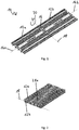
- Fig. 1 shows an embodiment of an on-floor channel 10 according to the invention. Shown is an on-floor channel for use in the timing of a sporting event.
- This type of on-floor channel can be used for example in the start and finish area or in the field of an intermediate measurement of a sporting event, which is protected by the on-floor channel, an electrical conductor for contacting antennas and an antenna.
- the on-floor channel 10 advantageously has a corrugation in order to avoid slipping of persons when crossing the on-floor channel 10. It is understood that the principle of the present invention can also be used in other fields of application, for example in the field of hose bridges.
- the on-floor channel 10 (not visible in the illustrated perspective view) runs a line element (in the field of time measurement usually an electrical conductor for contacting an antenna), which is to be protected by the bottom channel 10 mechanically against external force.
- the on-floor channel 10 absorbs forces exerted by athletes and vehicles.
- the floor channel 10 includes a first channel member 12a and a second channel member 12b.
- the conduit element runs in the interior of these channel elements 12a, 12b substantially along the longitudinal axes 14a, 14b of the channel elements 12a, 12b. In most cases, the conduit element enters the channel element on one end face of a channel element and out again on the other end face. If the channel element is connected at one end face with a further channel element, the line element can be transferred from one channel element directly into the other channel element.
- the Indian Fig. 1 shown on-floor channel 10 is in the operating position in which it can be placed flat on the ground.
- the channel elements are arranged one behind the other along their longitudinal axes 14a, 14b or along a common longitudinal axis.
- the arrangement in succession reaches a length through which a conduit element can be routed via a road or over a dirt road.
- the channel elements 12a, 12b are connected at their end sides via a connecting element 16.
- the channel elements are connected via a plurality of further connecting elements, whereby the stability is further increased.
- the function is not affected by the presence of a plurality of connecting elements in the present embodiment.
- the singular shape of the connecting element is used, it being understood that several connecting elements can also be used.
- the connecting element 16 is articulated.
- the connecting element 16 allows a rotation of the channel elements 12a, 12b to each other.
- Shown is an exemplary course of a rotation axis 18, around which the channel elements 12a, 12b can be rotated relative to each other.
- the illustrated arrow 20 visualizes the possible rotational movement.
- the axis of rotation 18 advantageously extends orthogonally to the longitudinal axes 14a, 14b of the channel elements 12a, 12b.
- the axis of rotation 18 continues to be parallel to the ground or parallel to a transverse direction of the channel elements 12a, 12b.
- the axis of rotation 18 can move parallel to itself during the rotation of the channel elements 12a, 12b and need not be clearly defined.
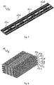
- Fig. 2 the on-floor channel 10 is shown in its transport position.
- the first channel element 12a is rotated about the axis of rotation 18 and is located on the second channel element 12b.
- the first channel member 12a is folded or folded onto the second channel member 12a.
- the underside 21a of the first channel element 12a can be seen.
- the channel elements 12a, 12b are arranged parallel to one another, in particular their longitudinal axes are oriented parallel to one another.
- the tops of the channel elements 12a, 12b are in contact with each other.
- first channel member 12a when the first channel member 12a is rotated toward the second channel member 12b, it may also be possible for the first channel member 12a to be rotated (flipped) below the second channel member 12b so that the bottoms of the channel members 12a, 12b are in contact.
- the channel elements 12a, 12b are connected by the connecting element 16.
- the conduit element is received in the transport position of the bottom channel 10 in the channel elements 12a, 12b. Accordingly, the conduit element in the region of the connecting element 16 is bent or bent.
- the present invention allows the assumption of the transport position or the assembly and disassembly of the on-floor channel without further assembly steps, such as the assembly of the channel elements or the insertion of the line element assembling, performing.
- the assembly and disassembly can thus be done more efficiently.
- shorter channel elements can be used without further effort, so that the on-floor channel is less bulky in its transport position and can be easily transported.
- Fig. 3 is a section of a sectional view of the bottom channel in the region of the connecting element 16 is shown.
- the illustrated floor channel is in the operating position.
- the articulated connecting element 16 connects the two channel elements 12a, 12b.
- the connecting element 16 is formed in one piece and has recesses 22a, 22b on both sides, which comprise cylindrical extensions 24a, 24b on the channel elements 12a, 12b.
- the cylindrical extensions 22a, 22b are preferably fixed on both sides to the respective channel element 12a, 12b, but can also be fixed on one side only.
- By the cylindrical extensions 24a, 24b bearing points are defined by which the connecting element 16 can be rotated.
- the illustrated connecting element 16 is rotatably supported on both sides. By rotation of the connecting element 16, a rotation of the channel elements 12a, 12b to each other take place. The rotation can be done in both directions.
- the connecting element 16 forms, so to speak, a kind of double hinge.
- Fig. 4 is a sectional view through the bottom channel in the transport position shown.
- the connecting element is rotated relative to both channel elements 12a, 12b, so that the channel elements 12a, 12b are arranged parallel to one another.
- the axis of rotation of the rotation of the channel elements 12a, 12b to each other can therefore be defined by the two bearing points. Part of the rotation takes place around the first bearing point, another part of the rotation takes place around the second bearing point.
- the connecting element 16 preferably has a rotational degree of freedom of 180 ° with respect to each of the two channel elements. Accordingly, the connecting element 16 can be rotated from its 0 ° position in the operating position of the floor channel in each case by 90 ° in both directions. In conjunction with a corresponding bearing on the other channel element, which also has a rotational degree of freedom of 180 °, thus resulting in a total degree of freedom of 360 ° of the channel elements 12a, 12b to each other. Consequently, the connected channel elements 12a, 12b are completely rotated around each other, so that a two-sided folding is possible. On the one hand, the channel elements 12a, 12b can thus be brought into contact with one another with their undersides 26 and, on the other hand, with their tops 26 '.
- Fig. 5 a detail view of the connecting element 16 is shown.
- the connecting element has on both sides recesses 22a, 22b and is insofar double-hook-shaped, as the recesses 22a, 22b are open on one side.
- the recesses 22a, 22b have a circular section-shaped cross-section.
- the diameter of the inner circle defined by the recesses 22a, 22b essentially corresponds to the outer diameter of the cylindrical extensions.
- the illustrated double hook-shaped design allows easy assembly with the channel elements.
- the channel elements can be detachably connected or fixed by being hooked together with the connecting element.
- the recesses interact with cylindrical extensions on the channel elements.
- the connecting element 16 consists of an elastically deformable material, so that the unilaterally open recesses 22a, 22b can act as a spring.
- the connecting element 16 deforms elastically during the reception of the cylindrical extensions and relaxes again when the cylindrical extensions are completely enclosed.
- the openings of the recesses 22a, 22b are funnel-shaped, so that the recesses 22a, 22b can bend when pressed onto the cylindrical extensions.
- the connecting element 16 connects the channel elements under tension, that is, a distance of the center of the recesses in a relaxed state is greater than in a state in which the connecting element connects two channel elements.
- the connecting element can also be rotatably mounted only on one side. Accordingly, only be defined on the side of the one channel element, a bearing point and the connecting element to be firmly connected to the other channel element. It is also possible that the recesses in the connecting element are not open on one side, but closed. The assembly can then be done for example by assembling several parts.
- the cylindrical extensions can also be provided on the connecting element and can cooperate with recesses in the channel elements.
- the connecting element could, for example, be articulated in that it is bone-shaped, wherein two cylindrical sections are connected by a connecting section. The cylindrical sections form the cylindrical extensions and can engage in corresponding recesses in the channel elements.
- the connecting element is articulated in that it is firmly connected to one or both channel elements and has its own elasticity. The rotation of the channel elements to each other then takes place by elastic deformation of the connecting element.
- the connecting element can also be fixedly connected to one or both channel elements and designed as a joint. Other articulated training to achieve the same function are conceivable.
- Fig. 6 the end face 28 of a channel element 12 is shown.
- four connectors 16 ', 16 ", 16"', 16 “” are provided to connect the channel members 12 to an adjacent channel member.
- the function of each connector is not affected by the use of multiple connectors.
- the stability can be increased.
- the plurality of connecting elements 16 ', 16 ", 16"', 16 “” are identical, with the use of differently designed connecting elements is possible. It is understood that more or fewer than four identical or differently formed connecting elements can be used. As in particular in the Fig.
- the end face 28 of a first channel member may denote the entire region (in the operating position of the bottom channel) facing the second channel member and the region of the channel member associated with the connector, respectively. Likewise, however, the end face may also designate the end face of the first channel element facing the second channel element in the operating position.
- Fig. 7 is a bottom channel 10 with a total of four channel elements 12a, 12b, 12c, 12d shown.
- the on-floor channel 10 is in the operating position for resting on the ground.
- Each channel element is connected to adjacent channel elements end face via a connecting element.
- the channel elements are mirror-inverted with respect to a transverse axis orthogonal to its longitudinal axis, so that in principle any number of channel elements can be joined together. This makes it possible to provide on-floor channels of any length based on the same basic components. In a running event, it is therefore possible to make the route in the start and finish area or in the interim time measurement arbitrarily wide. This is particularly advantageous for mass sports events.
- Fig. 8 is a bottom channel 10 with a total of eight channel elements 12a-12h shown in the transport position. Due to the degree of freedom of 360 ° between two adjacent channel elements, a folding in the manner of a concertina is made possible.
- the channel member 12d is in contact with the upper surface of the adjacent channel member 12c with its upper side in contact with the underside of the adjacent channel member 12e.
- Fig. 9 is a detailed view of two channel elements 12a, 12b in the region of their end faces, where they are connected to a connecting element 16, shown.
- the channel elements 12a, 12b are rounded in the region of their end faces 28a, 28b. Due to the rounded design, the rotation of the channel elements 12a, 12b around each other at a constant distance possible. The distance between the channel elements 12a, 12b is kept constant by the connecting element 16. Due to the rounded design, the distance remains constant even during the rotation, whereby a defined and stable course of the rotation is possible.
- the rounding thus corresponds to an at least partial rounding or chamfering of the channel elements at their end faces.
- the channel elements 12a, 12b are preferably partially planar in the region of their end faces.
- the channel elements 12a, 12b thus have surfaces 30a, 30b in the direction of their end faces 28a, 28b.
- the surfaces 30a, 30b are parallel and in contact with each other.
- the connecting element 16 may be elastically deformable and deform during the rotation of the contacting of the surfaces 30a, 30b. Accordingly, the distance between the recesses in the connecting element may be larger or smaller.
- the channel elements 12a, 12b may be elastically deformable in the region of their end faces and deform during the rotation. As a result, a fixation or a self-locking of the channel elements 12a, 12b is achieved to each other in the operating position of the floor channel.
- the stability and rigidity of the bottom channel in the operating position can be increased. Due to the fact that the end faces of the channel elements are in contact in the operating position of the bottom channel, a self-locking of the bottom channel or channel elements in the operating position of the bottom channel is achieved.
- a tensile force can be effected, through which the self-locking is achieved.
- the self-locking can be achieved by a partially planar design of the channel elements at their ends.
- a partially planar formation of at least one end face 28a, 28b a partial formation of the end face as a flat, orthogonal to the longitudinal axis of the channel elements extending plane 30a, 30b.
- FIG. 10 is again a detailed view of two channel elements 12a, 12b shown in the region of their end faces.
- the channel elements 12a, 12b have cutouts 32a, 32b in the region of their end faces.
- the conduit member 34 is received in the channel members and passes through both channel members 12a, 12b. Due to the thickness of the channel elements 12a, 12b required for sufficient stability, an excess length of the conduit element 34 would be necessary when the channel elements 12a, 12b are rotated relative to one another.
- the conduit element 34 would not block rotation of the channel elements 12a, 12b only if it were sufficiently long to overcome the excess distance from the end-side exit from the first channel elements 12a to the end face entry into the second channel element 12b due to the thickness of the channel elements can.
- cutouts 32a, 32b in the channel elements 12a, 12b in the region of their end faces this is avoided.
- the cutouts 32a, 32b receive the duct element 34 in the transport position of the bottom channel. Accordingly, no excess length of the conduit member is necessary to perform the rotation of the channel elements to each other.
- the cutouts 32a, 32b allow the rotation of the channel elements 12a, 12b relative to one another when the line element 34 is received, without having to provide an excess length of the line element.
- conduit member 34 is bent during rotation of the channel elements 12a, 12b to each other.
- cutouts 32a, 32b is also effected that the Abknickradius can be greater, whereby the mechanical load on the line member 34 is reduced.
- the kinking plane of the conduit element is moved inward, so to speak.
- a wedge-shaped configuration 36a, 36b of the channel elements 12a, 12b in the region of the course of the line element 34 is advantageous.
- the channel elements 12a, 12b taper in the direction of their end faces 28a, 28b or in the direction of the respective other channel element in this area to the Buckling radius of the conduit member 34 further increase when the floor channel is in the transport position.
- the wedge-shaped configuration can be done on one side, ie only in the direction of the top or bottom of the channel element, as well as on both sides.
- a section of a ground antenna 38 according to the invention is shown.
- the ground antenna 38 comprises a channel element 12, an electrical conductor 40 and an antenna 42, in the example illustrated a patch antenna.
- the antenna 42 can be driven by the electrical conductor 40.
- the electrical conductor 40 corresponds to the line element.
- a channel member includes a removable cover member that can be locked with a bottom element 44.
- the bottom member 44 of the channel member 12 is shown without cover.
- the conduit element 40 and on the other hand also the antenna 42 are protected against external force effects by the channel element 12.
- Another channel element or a further ground antenna can be connected via a connecting element.
- a further antenna in the further channel element can be driven by a line element 40 'which extends through both channel elements.
- the course of the line elements 40, 40 ' is shown by way of example in the figures. Another course is possible.
- FIG. 2 illustrates a timing system 46 in accordance with one aspect of the present invention.
- Timing system 46 includes a ground antenna 44 having a bottom channel 12a, 12b, an electrical conductor 40, and an antenna 42, a mobile transponder 48 that can wirelessly communicate with antenna 42, and a base station 50 that communicates with the antenna via electrical conductor 40 42 is connected.
- the time measuring system 46 is designed for a preferably mobile use in the timing of sports events such as marathon events, cycling, ski racing or car racing.
- the timing system 46 is built on site and dismantled after use again.
- the inventively hinged channel elements of the ground antenna an uncomplicated and quick assembly and disassembly and an efficient and space-saving transport possible. Through the channel elements electrical conductors and antennas are protected from the effects of force by athletes when crossing the timing.
- the Transponder 48 is carried by an athlete.
- the transponder 48 may be, for example, an active or passive transponder. In particular, it may be a UHF RFID transponder.
- the base station 50 may be in communication with a central server so that the results of the timekeeping may be provided in a network.
- the base station may also be connected directly to a display device for displaying the measured times.
Landscapes
- Engineering & Computer Science (AREA)
- Architecture (AREA)
- Civil Engineering (AREA)
- Structural Engineering (AREA)
- Physics & Mathematics (AREA)
- General Physics & Mathematics (AREA)
- Electric Cable Arrangement Between Relatively Moving Parts (AREA)
- Bridges Or Land Bridges (AREA)
- Details Of Aerials (AREA)
Description
- Die vorliegende Erfindung betrifft einen Aufbodenkanal zum Verlegen eines Leitungselements auf einem Untergrund und zum Schutz des Leitungselements vor externen Krafteinwirkungen, mit einem ersten Kanalelement und einem zweiten Kanalelement zur Aufnahme des Leitungselements; und einem Verbindungselement zum Verbinden des ersten Kanalelements mit dem zweiten Kanalelement an Stirnseiten des ersten Kanalelements und des zweiten Kanalelements.
- Aufbodenkanäle dieser Art werden beispielsweise als Kabelbrücken, Kabelkanäle oder Schlauchbrücken eingesetzt. Das Leitungselement soll vor externen Krafteinwirkungen geschützt werden. Externe Krafteinwirkungen bezeichnen in diesem Zusammenhang insbesondere alle Arten von Kräften durch Personen, Fahrzeuge oder abgestellte Gegenstände, die auf das Leitungselement einwirken. Beispielsweise soll ein elektrisches Kabel vor einer direkten Exposition gegenüber Personen oder Fahrzeugen, die das Kabel überqueren, geschützt werden.
- Dieser Schutz wird erreicht, indem das Leitungselement in einem Kanal auf dem Boden verlegt wird, in dem es vor externen Krafteinwirkungen geschützt ist. Der Aufbodenkanal bzw. die Kanalelemente sind dazu ausgebildet externe Krafteinwirkungen aufzunehmen und das Leitungselement zu schützen. Während des Betriebs des Aufbodenkanals befindet sich dieser demnach zumeist auf einem Untergrund. Die Kanalelemente sind entlang einer Längsachse hintereinander angeordnet und erlauben es eine bestimmte Länge zu überspannen, auf der das Leitungselement im Aufbodenkanal geschützt werden soll.
- Herkömmlicherweise werden mehrere Kanalelemente mittels Verbindungselementen zu einem Aufbodenkanal verbunden. Durch eine solche Aneinanderreihung mehrerer Elemente wird erreicht, dass mehr oder weniger beliebig lange Straßen, Fußgängerwege etc. überquert werden können. Je nachdem, welche Länge des Aufbodenkanals erforderlich ist, kann im Prinzip eine beliebige Anzahl an Kanalelementen kombiniert werden.
- Herkömmliche Aufbodenkanäle werden oft erst am Einsatzort je nach Anwendung über ein Verbindungselement zu einer erforderlichen Länge kombiniert, beispielsweise durch Zusammenstecken. Zumeist erlaubt das Verbindungselement dabei eine lösbare Verbindung. Es ist hierbei möglich, dass Verbindungselement fest mit dem ersten oder zweiten Kanalelement verbunden oder auch als separates Element ausgeführt ist. Normalerweise erlaubt das Verbindungselement insofern ein flexibles Verbinden, als die Kanalelemente lösbar und oder auch gegeneinander drehbar verbunden sind. Nach dem Kombinieren kann dann das Leitungselement eingelegt werden. Hierzu ist beispielsweise ein abnehmbarer Deckel vorgesehen, der zum Einlegen des Leitungselements abgenommen werden kann. Ebenfalls ist eine Ausgestaltung mit einem Querschnitt in Form eines Überstands, in den das Leitungselement eingelegt werden kann, möglich.
- In
WO 02/071566 A2 - In
DE 10 2006 048 474 A1 wird ein Abschluss- und/oder Verbindungsstück zur Befestigung am Ende wenigstens eines Abdeckprofils für Leitungen beschrieben. Bei dem Abschluss- und/oder Verbindungsstück sind erste zwischen dem Abschluss- und/oder Verbindungsstück und dem Abdeckprofil wirkende Verbindungsmittel zum Herstellen einer bezogen auf eine erste Achsrichtung radialen formschlüssigen Verbindung zwischen dem Abdeckprofil und dem Abschluss- und/oder Verbindungsstück durch Stecken oder Fügen sowie durch zweite in dem Abschluss- und/oder Verbindungsstück integrierte, zwischen diesem und dem Abdeckprofil wirkende und in dieses Profil eingreifende Verbindungsmittel für ein Fixieren der Verbindung in axialer Richtung vorgesehen. - In
US 2010/0265801 A1 werden ein Zeitmesssystem und ein Zeitmessverfahren beschrieben. Das System strahlt in eine längliche Zeitmesszone, sodass RFID Transponder in dieser Zone Identifikationssignale übermitteln, die zum Erzeugen einer den Wettkämpfern zugeordneten Zeitmessinformation verwendet werden. Eine Panelantenne ist bevorzugt am Boden vorgesehen, um die längliche Zeitmesszone zu erzeugen und das System wird bevorzugt in UHF betrieben. Der RFID Tag verwendet bevorzugt eine Einschnitt-Antenne und kann in eine Kreditkarte integriert werden. - In
WO 2015/004654 A1 wird ein biegbares Flachkabel offenbart. Das Flachkabel besteht aus stabilen, flachen Platten, die miteinander verbunden sind, um eine lange Kette zu bilden. Die Platten bestehen aus einem starren Material und weisen an Ihrer Unterseite Kanäle für elektrische Leiter auf. - In
GB 2510633 A - In
DE 2 312 987 A wird ein dachartig ausgebildetes Kabelabdeckteil offenbart. Das Kabelabdeckteil besteht vorzugsweise aus Kunststoff, mit nach oben vorstehenden Verbindungselementen zur aufeinanderfolgenden Verbindung der Kabelabdeckteile zu einer endlosen Kette. - In
WO 2009/011600 A1 werden ein Zeitmesssystem und ein Zeitmessverfahren offenbart. Eine längliche Zeitmessregion wird ausgeleuchtet, sodass ein darin befindlicher RFID Transponder ein Identifizierungssignal übermittelt. - Ein mögliches Einsatzszenario für Aufbodenkanäle findet sich im Bereich der Zeitmessung für Sportveranstaltungen, insbesondere Laufsportveranstaltungen. Sportler tragen Funkelemente (z.B. aktive oder passive RFID Tags) bei sich, die beispielsweise in eine Startnummer integriert oder am Schnürsenkel befestigt sein können. Im Fall von Radsportveranstaltungen ist es möglich am Lenker eines Fahrrads entsprechende Funkelemente anzubringen. Durch elektrische Leitungen im Aufbodenkanal werden Antennen kontaktiert, die ebenfalls im Aufbodenkanal enthalten, beidseitig zur Strecke vertikal positioniert oder auch in anderer Weise angeordnet sein können. Die Zeitmessung erfolgt dabei zumeist mittels einer entsprechenden Ausleseeinheit, die über elektrische Leiter mit der Antenne verbunden ist. Die Ausleseeinheit befindet sich üblicherweise seitlich der Strecke. Daher ist es erforderlich, dass ein elektrischer Leiter die Strecke überquert. Durch die Verwendung eines Aufbodenkanals wird dieser Leiter vor Einwirkungen durch Sportler oder Fahrzeuge, die den Aufbodenkanal überqueren, geschützt. Zudem kann erreicht werden, dass Sportler nicht von Kabeln auf der Strecke behindert werden. Beim Überqueren bzw. Passieren der Antenne erfolgt die Zeitmessung durch Kommunikation mit dem Funkelement. Die Zeitmessung erfolgt beispielsweise im Start- und Zielbereich oder auch als Zwischenzeitmessungen auf der Strecke.
- Eine Problemstellung in diesem Feld ist, dass Zeitmessungen bei Sportveranstaltungen oft mobil bzw. temporär erfolgen. Die Messung erfolgt für einen absehbaren Zeitraum, beispielsweise einen Tag. Zwar sind ebenfalls Anwendungen denkbar, bei denen eine festinstallierte Zeitmesseinrichtung vorteilhaft sein kann, jedoch wird ein Großteil der Sportveranstaltungen innerhalb einer absehbaren Zeit durchgeführt. Oft bleibt auch für den Auf- und Abbau nur ein begrenztes Zeitfenster. Demnach muss die Zeitmesseinrichtung komfortabel auf- und abbaubar sein. Normalerweise wird ein Aufbodenkanal zum Ort der Veranstaltung transportiert, um dort aufgebaut zu werden. Nach der Veranstaltung wird der Aufbodenkanal zum Transport wieder abgebaut. Oft werden entsprechende Zeitmesssysteme mitsamt dem zugehörigen Aufbodenkanal auch versendet.
- Die Verwendung herkömmlicher Aufbodenkanäle hat in diesem Anwendungsfeld den Nachteil, dass der Auf- und Abbau relativ viel Zeit in Anspruch nehmen kann. Zudem sind oft die zu transportierenden Einzelteile sperrig und schwer transportierbar. Schwierigkeiten beim Aufbau können sich beispielsweise auch ergeben, wenn mehrere Leitungselemente jeweils verschiedenen Antennen zugeordnet sind und entsprechend kontaktiert werden müssen.
- Die vorliegende Erfindung hat daher die Aufgabe einen Aufbodenkanal zum Verlegen eines Leitungselements und auf einem Untergrund und zum Schutz des Leitungselements vor externen Krafteinwirkungen zu schaffen. Insbesondere soll ein Aufbodenkanal geschaffen werden, der im Vergleich zu herkömmlichen Aufbodenkanälen besser transportierbar und/oder auf- und abbaubar ist. Zudem hat die vorliegende Erfindung die Aufgabe eine Bodenantenne sowie ein auf dieser Bodenantenne basierendes Zeitmesssystem zu schaffen.
- Gemäß einem Aspekt der Erfindung wird diese Aufgabe dadurch gelöst, dass das Verbindungselement gelenkartig ausgebildet ist und eine Drehbewegung des ersten Kanalelements in Bezug zu dem zweiten Kanalelement um eine Drehachse orthogonal zu einer ersten Längsachse des ersten Kanalelements und orthogonal zu einer zweiten Längsachse des zweiten Kanalelements erlaubt, durch die der Aufbodenkanal in eine Transportposition, in der die Kanalelemente parallel zueinander angeordnet sind und in eine Betriebsposition, in der die Kanalelemente entlang ihrer Längsachsen hintereinander angeordnet sind, gebracht werden kann,
wobei das Leitungselement ein elektrischer Leiter ist und das erste Kanalelement und das zweite Kanalelement zur Aufnahme des elektrischen Leiters und einer Antenne ausgebildet sind, wobei sich der elektrische Leiter und die Antenne in der Transportposition im Aufbodenkanal befinden können. - Das gelenkartig ausgebildete Verbindungselement erlaubt das Ausführen einer Drehbewegung der Kanalelemente zueinander. Beispielsweise kann das Verbindungselement in Form eines Gelenks ausgebildet sein und fest mit beiden Kanalelementen verbunden sein. Die Drehbewegung wird dann direkt durch das Gelenk erreicht. Denkbar ist auch die Verwendung eines Verbindungselements, das ein elastisches Material, beispielsweise ein Elastomer umfasst, durch dessen Flexibilität die Drehbewegung ausgeführt werden kann. Die Drehbewegung wird dann durch Deformieren des Verbindungselements erreicht. Ebenfalls ist eine drehbare Lagerung des Verbindungselements an zumindest einem Kanalelement möglich. Die Drehbewegung kommt dann durch ein Drehen bezüglich des zumindest einen Lagerpunkts zustande. Die gelenkartige Ausbildung umfasst also insbesondere eine Ausbildung als Gelenk, eine Ausbildung als elastisches Element
und eine Ausbildung als drehbar gelagertes festes Element bzw. Scharnier. Weitere Möglichkeiten zum Erreichen derselben Funktion sind denkbar. Das gelenkartig ausgebildete Verbindungselement kann mit einem oder mit beiden Kanalelement fest oder lösbar verbunden sein. Das Verbindungselement kann auch einen Teil des Kanalelements bezeichnen. Das Verbindungselement kann starr oder elastisch ausgebildet sein. - Üblicherweise wird das Leitungselemente entlang einer Längsachse der Kanalelemente durch die Kanalelemente geleitet. Die Drehbewegung erfolgt bezüglich einer Drehachse, die orthogonal zur Längsachse der Kanalelemente steht. Die Kanalelemente werden um 180° umeinander gedreht. Das Drehen entspricht demnach einem Zusammenklappen oder aus Zusammenfalten der Kanalelemente. Die Kanalelemente sind sozusagen faltbar. Durch die Drehung kann die Länge des Aufbodenkanals für den Transport vermindert werden. Im geklappten Zustand (also in der Transportposition des Aufbodenkanals) sind die Kanalelemente parallel zueinander angeordnet. Demnach ist die Länge des Aufbodenkanals geringer als in der Betriebsposition, sodass ein Transport bei gleichzeitig geringerem Auf- und Abbauaufwand vereinfacht wird. Die Kanalelemente können während des Transports verbunden bleiben.
- Der Aufbau des Aufbodenkanals erfolgt durch ein Aufklappen oder Auseinanderfalten der Kanalelemente (der Aufbodenkanal wird in die Betriebsposition gebracht). In der Betriebsposition weist der Aufbodenkanal durch die Aneinanderreihung der Kanalelemente eine maximale Länge auf. Am Einsatzort ist es ausreichend die Klappbewegung auszuführen und den Aufbodenkanal in die Betriebsposition zu bringen. Nach der Verwendung kann der Abbau durch einfaches Einklappen erfolgen. Hierdurch wird es möglich, die Auf- und Abbauvorgänge zu beschleunigen.
- Das erfindungsgemäße Verbindungselement hat gegenüber herkömmlichen Aufbodenkanälen den Vorteil, dass der Aufbodenkanal in vormontierter Weise transportiert werden kann. Das Leitungselement oder auch weitere Elemente können sich während des Transports im Aufbodenkanal befinden. Am Einsatzort erfolgt der Aufbau durch ein einfaches Auseinanderklappen. Es ist nicht erforderlich, dass zunächst Kanalelemente verbunden und dann ein Leitungselement eingelegt wird. Dadurch wird der Auf- und Abbau deutlich erleichtert. Zudem wird unfachmännisches oder falsches Aufbauen durch ungeschultes Personal verhindert oder zumindest er-schwert. Das separate Transportieren einzelner Kleinteilte wird vermieden, wodurch die Fehleranfälligkeit verringert werden kann. Des Weiteren kann auch die Stabilität erhöht werden.
- Ein weiterer Aspekt der Erfindung betrifft eine Bodenantenne zum Einsatz in der Zeitmessung bei Sportveranstaltungen, mit: einem Aufbodenkanal wie oben beschrieben; einem elektrischen Leiter, der in dem Auf-bodenkanal aufgenommen ist; und einer Antenne, insbesondere einer Patch-antenne oder einer Slotantenne, die in dem Aufbodenkanal aufgenommen und durch den elektrischen Leiter ansteuerbar ist. Die Antenne oder die An-tennen im Aufbodenkanal können durch entsprechende Zuleitungen (elektrische Kabel) im Aufbodenkanal mit einer entsprechenden Ansteuereinheit ne-ben der Strecke verbunden sein. Demnach entspricht der Aufbodenkanal mit eingelegter Antenne und entsprechender Zuleitung einer Bodenantenne. Im Bereich der Laufzeitmessung ist es vorteilhaft die Antenne direkt im Aufbodenkanal aufzunehmen und somit die Verwendung von unfallgefährlicheren und weniger zuverlässigen Seitenantennen zu vermeiden.
- Die Bodenantenne kann einfach und schnell am Einsatzort aufgeklappt und einsatzfähig gemacht werden.
- Ein weiterer Aspekt betrifft ein Zeitmesssystem zur Zeitmessung bei Sportveranstaltungen, mit: einer Bodenantenne wie zuvor beschrieben; einem mobilen Transponder zur drahtlosen Übermittlung von Signalen an die Antenne; und einer mobilen Basisstation, die über den elektrischen Leiter mit der Antenne verbunden ist, zur Ansteuerung der Antenne und zur Auswertung empfangener Signale von dem mobilen Transponder zur Zeitmessung. Das Zeitmesssystem kann einfach und schnell am Einsatzort auf- und abgebaut werden. Der Auf- und Abbau ist im Vergleich zu früheren System weniger fehleranfällig in Bezug auf die Verkabelung. Das Zeitmesssystem kann durch die faltbare Bodenantenne in relativ geringer Packungsgröße transportiert oder verschickt werden.
- In einer bevorzugten Ausgestaltung des erfindungsgemäßen Aufbodenkanals ist das Verbindungselement einstückig ausgebildet und an seiner Kontaktstelle zum ersten Kanalelement und/oder an seiner Kontaktstelle zum zweiten Kanalelement drehbar gelagert. Das Verbindungselement kann starr ausgeführt sein und muss keine eigene Flexibilität aufweisen. Ein einstückiges Verbindungselement kann effizient und kostengünstig hergestellt werden. Zudem ergeben sich Effizienzvorteile bei der Montage. Einerseits kann das Verbindungselement beidseitig drehbar gelagert sein, andererseits kann das Verbindungselement mit einem Kanalelement starr verbunden und nur am anderen Kanalelement drehbar gelagert sein.
- Gemäß einer Ausgestaltung weisen das erste Kanalelement und das zweite Kanalelement an ihren dem Verbindungselement zugewandten Stirnseiten zylinderförmige Fortsätze auf und weist das Verbindungselement eine erste und eine zweite Aussparung zur Aufnahme der zylinderförmigen Fortsätze auf; und/oder weist das Verbindungselement zylinderförmige Fortsätze auf und weisen das erste Kanalelement und das zweite Kanalelement an ihren dem Verbindungselement zugewandten Stirnseiten Aussparungen zur Aufnahme der zylinderförmigen Fortsätze auf, wobei die zylinderförmigen Fortsätze mit den Aussparungen zusammenwirken, um das Verbindungselement beidseitig drehbar zu lagern.
- Die Aussparungen nehmen die zylinderförmigen Fortsätze auf und erlauben eine Drehbewegung um die zylinderförmigen Fortsätze. Die zylinderförmigen Fortsätze können an den Kanalelementen oder am Verbindungselement vorgesehen sein. Die Aussparungen bilden jeweils das Gegenstück an den Kanalelementen oder am Verbindungselement. Die Aussparungen umfassen die zylinderförmigen Fortsätze vollständig oder teilweise und nehmen diese auf. Durch den runden Querschnitt der zylinderförmigen Fortsätze und der Aussparungen können die zylinderförmigen Fortsätze in den Aussparungen gedreht werden. Die Aussparungen und die zylinderförmigen Fortsätze bilden ein Drehlager. Die Drehachse ist parallel zu einer Zentralachse der zylinderförmigen Fortsätze. Eine Bewegung orthogonal zur Drehachse wird unterbunden, sodass die Länge des Aufbodenkanals definiert ist. Die zylinderförmigen Fortsätze können einseitig oder auf beiden Seiten mit dem Kanal- oder Verbindungselement verbunden sein. Diese Ausgestaltung der Kanalelemente und des Verbindungselements erlaubt eine einfache und kostengünstige Herstellung und Montage. Zudem kann eine robuste und beständige Verbindung erreicht werden. Zylinderförmig bedeutet in diesem Zusammenhang, dass die Fortsätze zumindest teilweise einen kreis- oder kreisabschnittförmigen Querschnitt haben. Insbesondere ist gemeint, dass die Fortsätze so ausgebildet sind, dass die Aussparungen um sie gedreht werden können.
- In einer bevorzugten Ausgestaltung weisen ein erstes Drehlager zwischen dem Verbindungselement und dem ersten Kanalelement und ein zweites Drehlager zwischen dem Verbindungselement und dem zweiten Kanalelement, jeweils einen Freiheitsgrad von 180°auf und bewirken einen Gesamtfreiheitsgrad des ersten Kanalelements und des zweiten Kanalelements von 360°. Die Zusammenwirkung entspricht einem Drehlager oder einem Drehgelenk. Die Zusammenwirkung des zylinderförmigen Fortsatzes
mit der Aussparung an der Verbindungsstelle des Verbindungselements mit dem ersten Kanalelement hat demnach einen Drehfreiheitsgrad von 180°. Die zweite Verbindungsstelle des Verbindungselements mit dem zweiten Kanalelement ist entsprechend ausgeführt. Beide Freiheitsgrade addieren sich zu einem Gesamtfreiheitsgrad von 360° der beiden Kanalelemente zueinander. Dieser Gesamtfreiheitsgrad von 360° bedingt, dass die beiden Kanalelementen beidseitig drehbar bzw. faltbar sind. Die Drehachse ist parallel zum Untergrund. - Die Verbindung der beiden Kanalelemente entspricht sozusagen einem Doppelscharnier. Einerseits kann eine Drehung durchgeführt werden, bei der das erste Kanalelement auf das zweite Kanalelement gedreht wird. Andererseits kann auch das erste Kanalelement unter das zweite Kanalelement gedreht werden. Je nachdem welche Drehung ausgeführt wird, kommen die Ober- oder Unterseiten der Kanalelemente miteinander in Kontakt in der parallelen Anordnung der Kanalelemente. Die Drehachsen beider Verbindungsstellen fallen dabei nicht aufeinander. Es ist möglich, zunächst um die eine und dann um die andere Verbindungsstelle zu drehen oder auch um beide Verbindungsstellen gleichzeitig zu drehen. Die Drehachse der Drehung der beiden Kanalelemente entspricht dann zunächst der Drehachse der Drehung um die erste Verbindungsstelle und dann der Drehachse der Drehung um die zweite Verbindungsstelle. Je nachdem in welche Richtung gedreht wird, sind in der Transportposition also die Oberseiten oder die Unterseiten der Kanalelemente einander zugewandt. Hierdurch werden die Flexibilität und der Komfort beim Auf- und Abbau weiter erhöht. Insbesondere wird die Flexibilität erhöht, wenn mehr als zwei Kanalelemente durch mehrere Verbindungselemente aneinandergereiht sind. Diese verketteten Kanalelemente können dann in der Art einer Ziehharmonika gefaltet werden. Ein Kanalelement mit jeweils einem benachbarten Kanalelement auf beiden Seiten ist dann mit seiner Oberseite in Kontakt mit der Oberseite seines ersten Nachbarn und mit seiner Unterseite in Kontakt mit der Unterseite seines zweiten Nachbarn.
- Gemäß einer weiteren bevorzugten Ausgestaltung ist das Verbindungselement doppelhakenförmig zum Einhaken an den zylinderförmigen Fortsätzen ausgebildet, wobei die Aussparungen einen im Wesentlichen kreisabschnittförmigen Querschnitt aufweisen und ein Innenkreisradius der Aussparungen jeweils einem Radius der zylinderförmigen Fortsätze an den Kanalelementen entspricht. Das doppelhakenförmige Verbindungselement hat zwei Aussparungen zur Aufnahme der zylinderförmigen Fortsätze. Hierdurch wird ein gelenkartiges Zusammenwirken erreicht. Die Aussparungen am Verbindungselement sind einseitig offen und können an den zylinderförmigen Fortsätzen eingehakt werden. Die offenen Aussparungen bilden sozusagen Haken. Hierdurch wir eine einfache Herstellung und ein einfacher Zusammenbau des Aufbodenkanals ermöglicht. Die Kanalelemente und das Verbindungselement können separat gefertigt und nach der Fertigung verbunden werden. Zudem ist die Verbindung lösbar. Das Verbinden und Lösen der Verbindung kann mittels eines geeigneten Werkzeugs erfolgen. Insbesondere werden aber auch ein Verbinden und ein Lösen ohne Werkzeug ermöglicht.
- In einer bevorzugten Ausgestaltung ist das Verbindungselement durch elastische Verformung lösbar an den zylinderförmigen Fortsätzen festlegbar; und/oder ist der Abstand der Mittelpunkte der durch die kreisabschnittförmigen Aussparungen beschriebenen Innenkreise in einem ersten Zustand des Verbindungselements durch elastische Verformung größer als in einem zweiten Zustand des Verbindungselements. Ein zumindest teilweise elastisches Verbindungselement kann sich beispielsweise beim Einhaken an den zylinderförmigen Fortsätzen kurzzeitig Verformen und sich dann in der eingehakten Position wieder entspannen. Die Verbindung ist daher nicht ohne weiteres, sondern nur durch eine Krafteinwirkung lösbar. Dieser Effekt kann beispielsweise dadurch erreicht werden, dass die Aussparungen in einem Winkelbereich <180° geöffnet sind. Ebenfalls ist die Verwendung einer Ausprägung als Rückzusicherung möglich, die einen Rückzug der zylinderförmigen Fortsätze nach dem Festlegen verhindert. Ein elastisches Verbindungselement kann beispielsweise in Zusammenwirkung mit teilweise flächig ausgebildeten Stirnseiten eine Erhöhung der Steifheit des Aufbodenkanals in seiner Betriebsposition und eine verbesserte mechanische Stabilität erlauben.
- Gemäß einer Ausgestaltung sind das erste Kanalelement und das zweite Kanalelement an ihren dem Verbindungselement zugewandten Stirnseiten in einem Querschnitt orthogonal zur Drehachse abgerundet ausgebildet. Durch die abgerundete Ausbildung wird erreicht, dass die Drehung der Kanalelemente zueinander auch dann nicht blockiert wird, wenn die Kanalelemente einander berühren. Ein Verklemmen wird verhindert. Die abgerundet ausgebildeten Kanalelemente berühren sich während des Drehens zueinander an wechselnden Stellen an ihren Abrundungen. Der Abstand der Lager, also der durch die zylinderförmigen Fortsätze definierten Drehachsen, bleibt gleich. Hierdurch wird die Stabilität bei der Drehung erhöht. Die Robustheit und Stabilität des Aufbodenkanals wird verbessert.
- Gemäß einer Ausgestaltung weisen das erste Kanalelement und das zweite Kanalelement an ihren dem Verbindungselement zugewandten Stirnseiten orthogonal zur Drehachse ausgebildete Ausschnitte auf, um in der Transportposition des Aufbodenkanals das Leitungselement aufzunehmen. In der Transportposition des Aufbodenkanals verläuft das Leitungselement von einem Kanalelement zum anderen. Das Leitungselement wird demnach ebenfalls um 180° abgeknickt. Je nach Leitungselement ist dabei ein Mindestradius für das Abknicken erforderlich, um eine Beschädigung des Leitungselements zu vermeiden. Dieser Mindestknickradius kann beispielsweise durch einen Längenüberschuss des Leitungselements im Bereich des Knickens erreicht werden. Der Längenüberschuss kann jedoch dazu führen, dass das Leitungselement in der Transportposition des Aufbodenkanals übersteht und damit gegenüber Transporteinwirkungen exponiert ist. Die ausgebildeten Ausschnitte ermöglichen, dass das Leitungselement in der Transportposition des Aufbodenkanals durch sie hindurch verläuft. Hierdurch wird der Radius für das Abknicken ohne Längenüberschuss vergrößert. Dies führt dazu, dass eine Exposition des Leitungselements in der Transportposition vermieden wird.
- In einer vorteilhaften Ausgestaltung verjüngen sich das erste Kanalelement und das zweite Kanalelement an ihren dem Verbindungselement zugewandten Stirnseiten im Bereich des Leitungselements keilförmig in Richtung des Verbindungselements, um einen Knickradius des Leitungselements in der Transportposition des Aufbodenkanals zu vergrößern. Der Mindestknickradius hängt von der Ausbildung der Kanalelemente in ihrem Bereich für die Aufnahme des Leitungselements ab. Insbesondere ist der Bereich der dem Verbindungselement zugewandten Stirnseite relevant. Durch die keilförmige Verjüngung wird der Knickradius bzw. der Mindestknickradius weiter erhöht. Das Leitungselement kann entlang der keilförmigen Ausbildung in einem größeren Abstand zur Drehachse verlaufen.
- Gemäß einer Ausgestaltung umfassen das erste Kanalelement und/oder das zweite Kanalelement an ihren dem Verbindungselement zugewandten Stirnseiten ein elastisch deformierbares Material, insbesondere ein Elastomer, und/oder sind parallel zur Drehachse und orthogonal zu ihren Längsachsen teilweise flächig ausgebildet, um eine Selbsthemmung in der Betriebsposition des Aufbodenkanals zu erreichen. Durch ein deformierbares Material an der Stirnseite wird erreicht, dass eine Einrastposition vordefinierbar ist. Wenn zumindest einseitig eine Fläche an einem Kanalelement mit dem anderen Kanalelement in Kontakt ist und der Abstand zwischen den Kanalelementen durch das Verbindungselement festgelegt ist, kann die erfindungsgemäße Drehbewegung des einen Kanalelements um das andere Kanalelement nur ausgeführt werden, wenn das Kanalelement mit der Fläche an der Stirnseite im Bereich dieser Fläche verformt wird. Hierdurch kann erreicht werden, dass eine Lage der Kanalelemente zueinander, also ein bestimmter Drehwinkel, fixiert werden kann. Durch die Verwendung des elastischen Materials ist eine Deformierung bzw. ein Eindrücken des elastischen Materials (oder des Verbindungselements) erforderlich, um diese vordefinierte relative Lage zu verlassen. Vorteilhafterweise entspricht die Betriebsposition der vordefinierten Lage, in der die Kanalelemente in einem Winkel von 0° zueinander stehen, also entlang ihrer Längsachsen hintereinander angeordnet sind. Hierdurch wird die Stabilität des Aufbodenkanals in der Betriebsposition erhöht und der Auf- und Abbau weiter vereinfacht.
- In einer weiteren Ausgestaltung sind die Kanalelemente symmetrisch bezüglich einer Ebene orthogonal zu ihren Längsachsen aufgebaut und können an beiden Stirnseiten über weitere Verbindungselemente mit weiteren Kanalelementen verbunden werden. Vorteilhafterweise erlaubt die Erfindung eine Kombination einer Mehrzahl an Kanalelementen. Die Kanalelemente sind über Verbindungselemente miteinander verbunden. Die Kanalelemente können aufeinander gefaltet werden, sodass sich in der Transportposition eine Art Stapel ergibt. Der Aufbau in die Betriebsposition erfolgt durch ein Auseinanderfalten in der Art einer Ziehharmonika beziehungsweise eines Faltenbalgs. In der Transportposition ist ein Kanalelement jeweils mit seiner Oberseite mit einem ersten benachbarten Kanalelement und mit seiner Unterseite mit einem weiteren Kanalelement in Kontakt. Durch die Verwendung mehrerer Kanalelemente können im Prinzip abhängig vom Anwendungsszenario Aufbodenkanäle beliebiger Länge realisiert werden. Die Kanalelemente bieten an beiden Stirnseiten bezüglich ihrer Längsachsen entsprechende Anschlussstellen für Verbindungselemente bzw. weitere Kanalelemente. Beispielsweise können beidseitig zylinderförmige Fortsätze vorgesehen sein, die mittels eines doppelhakenförmigen Verbindungselements verbunden werden können. Die symmetrische Ausgestaltung erlaubt eine kostengünstige Fertigung beispielsweise im Spritzgussverfahren.
- In einer weiteren vorteilhaften Ausgestaltung umfasst der Aufbodenkanal weiterhin ein drittes Kanalelement und ein viertes Kanalelement, die durch ein zweites Verbindungselement verbunden sind, wobei das dritte Kanalelement oder das vierte Kanalelement mit dem ersten oder dem zweiten Kanalelement durch ein drittes Verbindungselement verbunden sind. Diese Ausgestaltung betrifft demnach einen erfindungsgemäßen Aufbodenkanal bei dem vier Kanalelemente durch Verbindungselemente verbunden sind. Die vier Kanalelemente können beispielsweise jeweils eine Länge von ungefähr 58 cm oder auch einem Meter haben, sodass sich eine Gesamtlänge des Aufbodenkanals von ungefähr 5 Metern beziehungsweise 9 Metern ergibt.
- In einer Ausgestaltung sind das erste Kanalelement und das zweite Kanalelement zur Aufnahme eines elektrischen Leiters entlang ihrer Längsachsen und/oder zur Aufnahme einer Antenne, insbesondere einer Patchantenne oder einer Slotantenne, die durch den elektrischen Leiter ansteuerbar ist, ausgebildet. Der Aufbodenkanal weist entsprechende Einlegemöglichkeiten für Leitungen und Antennen auf. Oft ist die Verwendung einer separaten Antenne pro Kanalelement besonders vorteilhaft.
- In einer Ausgestaltung sind die Kanalelemente in einem Querschnitt orthogonal zu ihren Längsachsen beidseitig keilförmig ausgebildet, um in der Betriebsposition des Aufbodenkanals ein Überqueren des Leitungselements durch Personen und/oder Fahrzeuge zu ermöglichen. Durch die Keilform wird ein flaches Aufliegen auf dem Untergrund gewährleistet. Die Unfallgefahr bzw. die Komforteinschränkung beim Überqueren des Aufbodenkanals mit einem Fahrzeug oder zu Fuß wird reduziert.
- In einer Ausgestaltung umfassen das erste Kanalelement und das zweite Kanalelement jeweils ein Bodenelement mit einer Ausnehmung und ein Abdeckelement mit einem Klemmfortsatz, wobei das Bodenelement durch ein Eingreifen des Klemmfortsatzes in die Ausnehmung trennbar mit dem Abdeckelement verrastet werden kann. Durch diesen Verrastmechanismus wird eine einfache Möglichkeit geschaffen, Zugang zum Leitungselement bzw. zu einer Antenne im Aufbodenkanal zu bekommen.
- Es versteht sich, dass die vorstehend genannten und die nachstehend noch zu erläuternden Merkmale nicht nur in der jeweils angegebenen Kombination, sondern auch in anderen Kombinationen oder in Alleinstellung verwendbar sind, ohne den Rahmen der vorliegenden Erfindung zu verlassen.
- Die Erfindung wird nachfolgend anhand einiger ausgewählter Ausführungsbeispiele im Zusammenhang mit den beiliegenden Zeichnungen näher beschrieben und erläutert. Es zeigen:
- Fig. 1
- eine perspektivische Darstellung eines erfindungsgemäßen Aufbodenkanals in der Betriebsposition;
- Fig. 2
- eine perspektivische Darstellung eines erfindungsgemäßen Aufbodenkanals in der Transportposition;
- Fig. 3
- eine Schnittdarstellung einer Verbindung zweier Kanalelemente mit einem Verbindungselement in der Betriebsposition des Aufbodenkanals;
- Fig. 4
- eine Schnittdarstellung einer Verbindung zweier Kanalelemente mit einem Verbindungselement in der Transportposition des Aufbodenkanals;
- Fig. 5
- eine Darstellung eines doppelhakenförmig ausgebildeten Verbindungselements;
- Fig. 6
- eine Darstellung eines Kanalelements mit vier eingehakten Verbindungselementen;
- Fig. 7
- eine Darstellung eines Aufbodenkanals mit vier Kanalelemente in der Betriebsposition;
- Fig. 8
- eine Darstellung eines Aufbodenkanals mit einer Mehrzahl an Kanalelementen in der Transportposition;
- Fig. 9
- eine Schnittdarstellung eines Ausschnitts an der Stirnseite eines Kanalelements und einer keilförmigen Verjüngung im Bereich des Leitungselements;
- Fig. 10
- eine Darstellung eines beispielhaften Verlauf eines Leitungselements in der Transportposition des Aufbodenkanals;
- Fig. 11
- eine Darstellung einer erfindungsgemäßen Bodenantenne mit einem Aufbodenkanal, einer Antenne und einem Leitungselement; und
- Fig. 12
- eine Darstellung eines erfindungsgemäßen Zeitmesssystems.
-
Fig. 1 zeigt ein Ausführungsbeispiel eines erfindungsgemäßen Aufbodenkanals 10. Dargestellt ist ein Aufbodenkanal zum Einsatz in der Zeitmessung bei einer Sportveranstaltung. Diese Art von Aufbodenkanal kann beispielsweise im Start- und Zielbereich oder auch im Bereich einer Zwischenzeitmessung einer Sportveranstaltung eingesetzt werden, wobei durch den Aufbodenkanal ein elektrischer Leiter zum Kontaktieren von Antennen sowie eine Antenne geschützt wird. Auf seiner Oberseite weist der Aufbodenkanal 10 vorteilhafterweise eine Riffelung auf, um ein Ausrutschen von Personen beim Überqueren des Aufbodenkanals 10 zu vermeiden. Es versteht sich, dass das Prinzip der vorliegenden Erfindung auch in anderen Anwendungsbereichen, wie zum Beispiel im Bereich der Schlauchbrücken, eingesetzt werden kann. - Im Aufbodenkanal 10 (in der dargestellten perspektivischen Ansicht nicht sichtbar) verläuft ein Leitungselement (im Bereich der Zeitmessung üblicherweise ein elektrischer Leiter zum Kontaktieren einer Antenne), das durch den Aufbodenkanal 10 mechanisch vor externen Krafteinwirkungen geschützt werden soll. Insbesondere nimmt der Aufbodenkanal 10 Kräfte auf, die von Sportlern und Fahrzeugen ausgeübt werden. Der Aufbodenkanal 10 umfasst ein erstes Kanalelement 12a und ein zweites Kanalelement 12b. Das Leitungselement verläuft im Inneren dieser Kanalelemente 12a, 12b im Wesentlichen entlang der Längsachsen 14a, 14b der Kanalelemente 12a, 12b. Zumeist tritt das Leitungselement an der einen Stirnseite eines Kanalelements in das Kanalelement ein und an der anderen Stirnseite wieder aus. Wenn das Kanalelement an einer Stirnseite mit einem weiteren Kanalelement verbunden ist, kann das Leitungselement vom einen Kanalelement direkt in das andere Kanalelement übergeleitet werden.
- Der in der
Fig. 1 dargestellte Aufbodenkanal 10 befindet sich in der Betriebsposition, in der er flach auf den Untergrund aufgelegt werden kann. In der Betriebsposition sind die Kanalelemente entlang ihrer Längsachsen 14a, 14b bzw. entlang einer gemeinsamen Längsachse hintereinander angeordnet. Durch die Anordnung hintereinander wird eine Länge erreicht, durch die ein Leitungselement über eine Straße oder über einen Feldweg geleitet werden kann. - Die Kanalelemente 12a, 12b sind an ihren Stirnseiten über ein Verbindungselement 16 verbunden. Im dargestellten Ausführungsbeispiel sind die Kanalelemente über mehrere weitere Verbindungselemente verbunden, wodurch die Stabilität weiter erhöht wird. Die Funktion wird durch das Vorhandensein mehrerer Verbindungselemente im vorliegenden Ausführungsbeispiel nicht beeinflusst. Im Folgenden wird die Singularform des Verbindungselements verwendet, wobei es sich versteht, dass auch mehrere Verbindungselemente eingesetzt werden können.
- Das Verbindungselement 16 ist gelenkartig ausgebildet. Das Verbindungselement 16 erlaubt eine Drehung der Kanalelemente 12a, 12b zueinander. Dargestellt ist ein beispielhafter Verlauf einer Drehachse 18, um die die Kanalelemente 12a, 12b gegenüber einander gedreht werden können. Der dargestellte Pfeil 20 visualisiert die mögliche Drehbewegung.
- Durch eine Drehbewegung der Kanalelemente 12a, 12b zueinander bezüglich der Drehachse 18 kann der Aufbodenkanal von der Betriebsposition, wie in
Fig. 1 dargestellt, in die Transportposition, wie inFig. 2 dargestellt, gebracht werden. Die Drehachse 18 verläuft dabei vorteilhafterweise orthogonal zu den Längsachsen 14a, 14b der Kanalelemente 12a, 12b. Im dargestellten Ausführungsbeispiel verläuft die Drehachse 18 weiterhin parallel zum Untergrund bzw. parallel zu einer Querrichtung der Kanalelemente 12a, 12b. Die Drehachse 18 kann sich während des Drehens der Kanalelemente 12a, 12b parallel zu sich selbst verschieben und muss nicht eindeutig definiert sein. - In
Fig. 2 ist der Aufbodenkanal 10 in seiner Transportposition dargestellt. Das erste Kanalelement 12a ist um die Drehachse 18 gedreht und befindet sich auf dem zweiten Kanalelement 12b. In anderen Worten wird das erste Kanalelement 12a auf das zweite Kanalelement 12a geklappt oder gefaltet. InFig. 2 ist demnach die Unterseite 21a des ersten Kanalelements 12a zu sehen. Die Kanalelemente 12a, 12b sind parallel zueinander angeordnet, insbesondere sind ihre Längsachsen parallel zueinander orientiert. Die Oberseiten der Kanalelemente 12a, 12b befinden sich in Kontakt zueinander. Abgesehen von der inFig.2 dargestellten Drehung des ersten Kanalelements 12a auf das zweite Kanalelement 12b kann es auch möglich sein, dass das erste Kanalelement 12a unter das zweite Kanalelement 12b gedreht (geklappt) wird, sodass die Unterseiten der Kanalelemente 12a, 12b in Kontakt zueinander sind. - Auch in der Transportposition des Aufbodenkanals 10 sind die Kanalelemente 12a, 12b durch das Verbindungselement 16 verbunden. Üblicherweise ist das Leitungselement in der Transportposition des Aufbodenkanals 10 in den Kanalelementen 12a, 12b aufgenommen. Entsprechend ist das Leitungselement im Bereich des Verbindungselements 16 abgeknickt oder gebogen.
- Im Vergleich mit früheren Aufbodenkanälen, bei denen das Verbindungselement nicht erfindungsgemäß gelenkartig ausgebildet war, erlaubt die vorliegende Erfindung das Einnehmen der Transportposition bzw. das Auf- und Abbauen des Aufbodenkanals ohne weitere Montageschritte, wie zum Beispiel das Zusammensetzen der Kanalelemente oder das Einlegen des Leitungselements nach dem Zusammensetzen, durchzuführen. Der Auf- und Abbau kann damit effizienter erfolgen. Zudem können ohne weiteren Aufwand auch kürzere Kanalelemente verwendet werden, sodass der Aufbodenkanal in seiner Transportposition weniger sperrig ist und einfacher transportiert werden kann.
- In
Fig. 3 ist ein Ausschnitt einer Schnittansicht des Aufbodenkanals im Bereich des Verbindungselements 16 dargestellt. Der dargestellte Aufbodenkanal befindet sich in der Betriebsposition. Das gelenkartig ausgebildete Verbindungselement 16 verbindet die beiden Kanalelemente 12a, 12b. Das Verbindungselement 16 ist einstückig ausgebildet und weist beidseitig Aussparungen 22a, 22b auf, die zylinderförmige Fortsätze 24a, 24b an den Kanalelementen 12a, 12b umfassen. Die zylinderförmigen Fortsätze 22a, 22b sind bevorzugt auf beiden Seiten am jeweiligen Kanalelement 12a, 12b fixiert, können jedoch auch nur einseitig fixiert sein. Durch die zylinderförmigen Fortsätze 24a, 24b sind Lagerpunkte definiert, um die das Verbindungselement 16 gedreht werden kann. Das dargestellte Verbindungselement 16 ist beidseitig drehbar gelagert. Durch eine Drehung des Verbindungelements 16 kann eine Drehung der Kanalelemente 12a, 12b zueinander erfolgen. Die Drehung kann in beide Richtungen erfolgen. Das Verbindungselement 16 bildet sozusagen eine Art Doppelscharnier. - In
Fig. 4 ist eine Schnittansicht durch den Aufbodenkanal in der Transportposition dargestellt. Im Vergleich zuFig. 3 ist das Verbindungselement gegenüber beiden Kanalelementen 12a, 12b gedreht, sodass die Kanalelemente 12a, 12b parallel zueinander angeordnet sind. Die Drehachse der Drehung der Kanalelemente 12a, 12b zueinander kann demnach durch die beiden Lagerpunkte definiert sein. Ein Teil der Drehung erfolgt um den ersten Lagerpunkt, ein weiterer Teil der Drehung erfolgt um den zweiten Lagerpunkt. - Das Verbindungselement 16 weist bevorzugt gegenüber jedem der beiden Kanalelemente einen Drehfreiheitsgrad von 180° auf. Demnach kann das Verbindungselement 16 ausgehend von seiner 0° Stellung in der Betriebsposition des Aufbodenkanals jeweils in beide Richtungen um 90° gedreht werden. Im Zusammenspiel mit einer entsprechenden Lagerung am anderen Kanalelement, die ebenfalls einen Drehfreiheitsgrad von 180° aufweist, ergibt sich somit ein Gesamtfreiheitsgrad von 360° der Kanalelemente 12a, 12b zueinander. Folglich können die verbundenen Kanalelemente 12a, 12b komplett umeinander gedreht werden, sodass ein beidseitiges Zusammenklappen ermöglicht wird. Einerseits können die Kanalelemente 12a, 12b also mit ihren Unterseiten 26 in Kontakt zueinander gebracht werden und andererseits mit ihren Oberseiten 26'.
- In
Fig. 5 ist eine Detailansicht des Verbindungselements 16 dargestellt. Das Verbindungselement weist beidseitig Aussparungen 22a, 22b auf und ist insofern doppelhakenförmig ausgebildet, als die Aussparungen 22a, 22b einseitig geöffnet sind. Die Aussparungen 22a, 22b weisen einen kreisabschnittförmigen Querschnitt auf. Der Durchmesser des durch die Aussparungen 22a, 22b definierten Innenkreises entspricht im Wesentlichen dem Außendurchmesser der zylinderförmigen Fortsätze. Durch die dargestellte doppelhakenförmige Ausbildung wird ein einfaches Zusammensetzen mit den Kanalelementen ermöglicht. Insbesondere können die Kanalelemente durch Zusammenhaken mit dem Verbindungselement lösbar verbunden bzw. festgelegt werden. Hierzu wirken die Aussparungen mit zylinderförmigen Fortsätzen an den Kanalelementen zusammen. - Vorteilhafterweise besteht das Verbindungselement 16 aus einem elastisch deformierbaren Material, sodass die einseitig offenen Aussparungen 22a, 22b als Feder wirken können. Das Verbindungselement 16 verformt sich während des Aufnehmens der zylinderförmigen Fortsätze elastisch und entspannt sich wieder, wenn die zylinderförmigen Fortsätze vollständig umfasst sind. Hierzu sind die Öffnungen der Aussparungen 22a, 22b trichterförmig ausgebildet, sodass sich die Aussparungen 22a, 22b beim Aufdrücken auf die zylinderförmigen Fortsätze aufbiegen können. Es ist zudem möglich, dass das Verbindungselement 16 die Kanalelemente unter Spannung verbindet, dass also ein Abstand der Mittelpunkt der Aussparungen in einem entspannten Zustand größer ist als in einem Zustand, in dem das Verbindungselement zwei Kanalelemente verbindet.
- In anderen Ausführungsformen der Erfindung kann das Verbindungselement auch nur einseitig drehbar gelagert sein. Demnach kann nur auf der Seite des einen Kanalelements ein Lagerpunkt definiert sein und das Verbindungselement mit dem anderen Kanalelement fest verbunden sein. Ebenfalls möglich ist, dass die Aussparungen im Verbindungselement nicht einseitig offen, sondern geschlossen sind. Die Montage kann dann beispielsweise durch Zusammensetzen mehrerer Teile erfolgen.
- Des Weiteren ist ebenfalls eine Umkehrung des dargestellten Prinzips der drehbaren Lagerung insofern möglich, als die zylinderförmigen Fortsätze auch am Verbindungselement vorgesehen sein können und mit Aussparungen in den Kanalelementen zusammenwirken können. In diesem Fall könnte das Verbindungselement beispielsweise dahingehend gelenkartig ausgebildet sein, dass es knochenförmig ausgebildet ist, wobei zwei zylindrische Teilstücke durch ein Verbindungsteilstück verbunden sind. Die zylindrischen Teilstücke bilden die zylinderförmigen Fortsätze und können in entsprechende Aussparungen in den Kanalelementen eingreifen.
- In weiteren Ausführungsformen der Erfindung ist es auch möglich, dass das Verbindungselement insofern gelenkartig ausgebildet ist, dass es mit einem oder mit beiden Kanalelementen fest verbunden ist und eine eigene Elastizität aufweist. Die Drehung der Kanalelemente zueinander erfolgt dann durch elastische Verformung des Verbindungselements. Alternativ kann das Verbindungselement auch mit einem oder mit beiden Kanalelementen fest verbunden und als Gelenk ausgebildet sein. Weitere gelenkartige Ausbildungen zum Erreichen derselben Funktion sind denkbar.
- In
Fig. 6 ist die Stirnseite 28 eines Kanalelements 12 dargestellt. Im dargestellten Ausführungsbeispiel sind vier Verbindungselemente 16', 16", 16"', 16"" vorgesehen, um das Kanalelemente 12 mit einem benachbarten Kanalelement zu verbinden. Die Funktion des einzelnen Verbindungselements wird durch die Verwendung mehrere Verbindungselemente nicht beeinflusst. Die Stabilität kann erhöht werden. Bevorzugt sind die mehreren Verbindungselemente 16', 16", 16"', 16"" identisch ausgebildet, wobei auch die Verwendung unterschiedlich ausgebildeter Verbindungselemente möglich ist. Es versteht sich, dass auch mehr oder weniger als vier identische oder unterschiedlich ausgebildete Verbindungselemente verwendet werden können. Wie insbesondere in derFig. 6 dargestellt kann hierin die Stirnseite 28 eines ersten Kanalelements den gesamten dem zweiten Kanalelement zugewandten Bereich (in der Betriebsposition des Aufbodenkanals) bzw. den dem Verbindungselement zugeordneten Bereich des Kanalelements bezeichnen. Ebenfalls kann die Stirnseite aber auch die in der Betriebsposition dem zweiten Kanalelement zugewandte Stirnfläche des ersten Kanalelements bezeichnen. - In
Fig. 7 ist ein Aufbodenkanal 10 mit insgesamt vier Kanalelementen 12a, 12b, 12c, 12d dargestellt. Der Aufbodenkanal 10 befindet sich in der Betriebsposition zur Auflage auf dem Untergrund. Jedes Kanalelement ist mit benachbarten Kanalelementen stirnseitig über ein Verbindungselement verbunden. In der dargestellten Ausführungsform sind die Kanalelemente spiegelbildlich bezüglich einer Querachse orthogonal zu ihrer Längsachse ausgebildet, sodass im Prinzip eine beliebige Anzahl an Kanalelementen zusammengefügt werden kann. Hierdurch wird es ermöglicht, Aufbodenkanäle mit beliebiger Länge auf Basis derselben Grundkomponenten bereitzustellen. Bei einer Laufsportveranstaltung wird es also möglich, die Streckenführung im Start- und Zielbereich oder auch im Bereich der Zwischenzeitmessung beliebig breit zu gestalten. Dies ist insbesondere bei Massensportveranstaltungen von Vorteil. - In
Fig. 8 ist ein Aufbodenkanal 10 mit insgesamt acht Kanalelementen 12a-12h in der Transportposition dargestellt. Durch den Freiheitsgrad von 360° zwischen zwei benachbarten Kanalelementen wird ein Zusammenfalten in der Art einer Ziehharmonika ermöglicht. Beispielsweise ist das Kanalelement 12d mit seiner Oberseite in Kontakt mit der Oberseite des benachbarten Kanalelements 12c und mit seiner Unterseite in Kontakt mit der Unterseite des benachbarten Kanalelements 12e. - In
Fig. 9 ist eine Detailansicht zweier Kanalelemente 12a, 12b im Bereich ihrer Stirnseiten, an denen sie mit einem Verbindungselement 16 verbunden sind, dargestellt. Die Kanalelemente 12a, 12b sind im Bereich ihrer Stirnseiten 28a, 28b abgerundet ausgebildet. Durch die abgerundete Ausbildung wird die Drehung der Kanalelemente 12a, 12b umeinander bei konstantem Abstand möglich. Der Abstand zwischen den Kanalelementen 12a, 12b wird durch das Verbindungselement 16 konstant gehalten. Durch die abgerundete Ausbildung bleibt der Abstand auch während der Drehung konstant, wodurch ein definierter und stabiler Verlauf der Drehung ermöglich ist. Die Abrundung entspricht somit einer zumindest partiellen Verrundung oder Anfasung der Kanalelemente an ihren Stirnseiten. - Bevorzugt sind die Kanalelemente 12a, 12b im Bereich ihrer Stirnseiten zudem teilweise flächig ausgebildet. Die Kanalelemente 12a, 12b weisen also in Richtung ihrer Stirnseiten 28a, 28b Flächen 30a, 30b auf. In der Betriebsposition des Aufbodenkanals sind die Flächen 30a, 30b parallel und in Kontakt zueinander. Dadurch, dass der Abstand zwischen den Kanalelementen 12a, 12b durch das Verbindungselement 16 definiert ist, ist eine Drehung der Kanalelemente 12a, 12b umeinander nur durch eine elastische Verformung möglich. Einerseits kann das Verbindungselement 16 elastisch deformierbar ausgebildet sein und sich bei der Drehung aus der Kontaktierung der Flächen 30a, 30b verformen. Demnach kann der Abstand zwischen den Aussparungen im Verbindungselement größer oder kleiner sein. Andererseits können auch die Kanalelemente 12a, 12b im Bereich ihrer Stirnseiten elastisch deformierbar sein und sich bei der Drehung verformen. Hierdurch wird eine Fixierung bzw. eine Selbsthemmung der Kanalelemente 12a, 12b zueinander in der Betriebsposition des Aufbodenkanals erreicht. Die Stabilität und Steifheit des Aufbodenkanals in der Betriebsposition kann erhöht werden. Dadurch, dass die Stirnseiten der Kanalelemente in der Betriebsposition des Aufbodenkanals in Kontakt stehen, wird eine Selbsthemmung des Aufbodenkanals bzw. der Kanalelemente in der Betriebsposition des Aufbodenkanals erreicht. Insbesondere kann durch ein elastisches Material an den Stirnseiten oder durch ein elastisches Verbindungselement zwischen den beiden Kanalelementen eine Zugkraft bewirkt werden, durch die die Selbsthemmung erreicht wird. Zusätzlich oder alternativ kann die Selbsthemmung durch eine teilweise flächige Ausbildung der Kanalelemente an ihren Stirnseiten erreicht werden. Wie insbesondere in der
Fig. 9 dargestellt bezeichnet eine teilweise flächige Ausbildung zumindest einer Stirnseite 28a, 28b eine teilweise Ausbildung der Stirnseite als flache, orthogonal zur Längsachse der Kanalelemente verlaufende Ebene 30a, 30b. Durch die Selbsthemmung wird ein Spiel zwischen den Kanalelementen wird verhindert. Insbesondere wird die Klappbewegung in die Transportposition gehemmt. Ebenfalls wird aber auch eine Drehung bzw. ein Spiel bezüglich einer Achse senkrecht zum Untergrund gehemmt. Die Selbsthemmung wirkt bezüglich aller möglichen Drehbewegungen der Kanalelemente zueinander. - In
Fig. 10 ist erneut eine Detailansicht zweier Kanalelemente 12a, 12b im Bereich ihrer Stirnseiten dargestellt. Die Kanalelemente 12a, 12b weisen im Bereich ihrer Stirnseiten Ausschnitte 32a, 32b auf. Das Leitungselement 34 ist in den Kanalelementen aufgenommen und verläuft durch beide Kanalelemente 12a, 12b hindurch. Aufgrund der für eine ausreichende Stabilität erforderlichen Dicke der Kanalelemente 12a, 12b wäre beim Drehen der Kanalelemente 12a, 12b zueinander eine Überschusslänge des Leitungselements 34 nötig. Das Leitungselement 34 würde nur dann eine Drehung der Kanalelemente 12a, 12b zueinander nicht blockieren, wenn es ausreichend lang wäre, um die durch die Dicke der Kanalelemente bedingte Überschussstrecke vom stirnseitigen Austritt aus dem ersten Kanalelemente 12a zum stirnseitigen Eintritt in das zweite Kanalelement 12b überwinden zu können. Anders ausgedrückt sind die Stirnseiten 28a, 28b der Kanalelemente 12a, 12b zwar in der Betriebsposition des Aufbodenkanals in unmittelbarem Kontakt, in der Transportposition jedoch nicht. Wenn das Leitungselement also durch stirnseitige Öffnungen in den Kanalelementen 12a, 12b aus- und eintreten würde, wäre hierzu die erforderliche Länge in der Transportposition größer als in der Betriebsposition. Zudem würde das Leitungselement in der Transportposition über die Stirnseiten überstehen und wäre damit gegenüber externen Einwirkungen beim Transport exponiert. - Durch die vorgesehenen Ausschnitte 32a, 32b in den Kanalelementen 12a, 12b im Bereich ihrer Stirnseiten wird dies vermieden. Die Ausschnitte 32a, 32b nehmen in der Transportposition des Aufbodenkanals das Leitungselement 34 auf. Demnach ist keine Überschusslänge des Leitungselements notwendig, um die Drehung der Kanalelemente zueinander ausführen zu können. Die Ausschnitte 32a, 32b ermöglichen die Drehung der Kanalelemente 12a, 12b zueinander bei aufgenommenem Leitungselement 34, ohne dass eine Überschusslänge des Leitungselements vorgesehen sein muss.
- Zudem wird das Leitungselement 34 beim Drehen der Kanalelemente 12a, 12b zueinander abgeknickt. Durch die Ausschnitte 32a, 32b wird ebenfalls bewirkt, dass der Abknickradius dabei größer sein kann, wodurch die mechanische Belastung des Leitungselements 34 verringert wird. Die Knickebene des Leitungselements wird sozusagen nach innen verschoben.
- Weiterhin vorteilhaft ist eine keilförmige Ausgestaltung 36a, 36b der Kanalelemente 12a, 12b im Bereich des Verlaufs des Leitungselements 34. Die Kanalelemente 12a, 12b verjüngen sich in Richtung ihrer Stirnseiten 28a, 28b bzw. in Richtung des jeweils anderen Kanalelements in diesem Bereich, um den Knickradius des Leitungselements 34 weiter zu erhöhen, wenn sich der Aufbodenkanal in der Transportposition befindet. Hierdurch wird die mechanische Belastung des Leitungselements weiter vermindert. Die keilförmige Ausgestaltung kann dabei sowohl einseitig, also nur in Richtung der Ober- oder Unterseite des Kanalelements, als auch beidseitig erfolgen.
- In
Fig. 11 ist ein Abschnitt einer erfindungsgemäßen Bodenantenne 38 dargestellt. Die Bodenantenne 38 umfasst ein Kanalelement 12, einen elektrischen Leiter 40 und eine Antenne 42, im dargestellten Beispiel eine Patchantenne. Die Antenne 42 ist durch den elektrischen Leiter 40 ansteuerbar. Der elektrische Leiter 40 entspricht dem Leitungselement. Üblicherweise umfasst ein Kanalelement ein abnehmbares Abdeckelement, das mit einem Bodenelement 44 verrastet werden kann. Zur Verdeutlichung ist inFig. 11 das Bodenelement 44 des Kanalelements 12 ohne Abdeckelement dargestellt. - Durch das Kanalelement 12 wird demnach einerseits das Leitungselement 40 und andererseits auch die Antenne 42 vor externen Krafteinwirkungen geschützt. Ein weiteres Kanalelement, bzw. eine weitere Bodenantenne kann über ein Verbindungselement verbunden sein. In diesem Fall ist es möglich, dass eine weitere Antenne im weiteren Kanalelement durch ein Leitungselement 40' angesteuert wird, das durch beide Kanalelemente hindurch verläuft. Der Verlauf der Leitungselemente 40, 40' ist in den Figuren jeweils beispielhaft dargestellt. Auch ein anderer Verlauf ist möglich.
- In
Fig. 12 ist ein Zeitmesssystem 46 gemäß einem Aspekt der vorliegenden Erfindung dargestellt. Das Zeitmesssystem 46 umfasst eine Bodenantenne 44 mit einem Aufbodenkanal 12a, 12b, einem elektrischen Leiter 40 und einer Antenne 42, einen mobilen Transponder 48, der drahtlos mit der Antenne 42 kommunizieren kann und eine Basisstation 50, die über den elektrischen Leiter 40 mit der Antenne 42 verbunden ist. - Das Zeitmesssystem 46 ist für einen bevorzugt mobilen Einsatz in der Zeitmessung bei Sportveranstaltungen wie beispielsweise Marathonveranstaltungen, Radrennen, Skirennen oder Autorennen ausgebildet. Das Zeitmesssystem 46 wird am Einsatzort aufgebaut und nach dem Einsatz wieder abgebaut. Durch die erfindungsgemäß klappbaren Kanalelemente der Bodenantenne werden ein unkomplizierter und schneller Auf- und Abbau sowie ein effizienter und platzsparender Transport ermöglicht. Durch die Kanalelemente werden elektrische Leiter und Antennen vor Krafteinwirkungen durch Sportler beim Überqueren der Zeitmessstelle geschützt.
- In der (mobilen) Basisstation 50 werden Signale des Transponders 48 ausgewertet, die über die Antenne 42 empfangen werden. Der Transponder 48 wird von einem Sportler bei sich getragen. Bei dem Transponder 48 kann es sich beispielsweise um einen Aktiv- oder Passivtransponder handeln. Insbesondere kann es sich um einen UHF RFID Transponder handeln. Die Basisstation 50 kann beispielsweise mit einem zentralen Server in Kommunikation stehen, sodass die Ergebnisse der Zeitmessung in einem Netzwerk bereitgestellt werden können. Die Basisstation kann auch direkt an ein Anzeigegerät zum Anzeigen der gemessenen Zeiten angeschlossen sein.
Claims (15)
- Aufbodenkanal (10) zum Verlegen eines Leitungselements (34) auf einem Untergrund und zum Schutz des Leitungselements (34) vor externen Krafteinwirkungen, mit:einem ersten Kanalelement (12a) und einem zweiten Kanalelement (12b) zur Aufnahme des Leitungselements (34); undeinem Verbindungselement (16) zum Verbinden des ersten Kanalelements (12a) mit dem zweiten Kanalelement (12b) an Stirnseiten (28a, 28b) des ersten Kanalelements (12a) und des zweiten Kanalelements (12b),wobei das Verbindungselement (16) gelenkartig ausgebildet ist und eine Drehbewegung des ersten Kanalelements (12a) in Bezug zu dem zweiten Kanalelement (12b) um eine Drehachse (18) orthogonal zu einer ersten Längsachse (14a) des ersten Kanalelements (12a) und orthogonal zu einer zweiten Längsachse (14b) des zweiten Kanalelements (12b) erlaubt, durch die der Aufbodenkanal (10) in eine Transportposition, in der die Kanalelemente (12a, 12b) parallel zueinander angeordnet sind und in eine Betriebsposition, in der die Kanalelemente (12a, 12b) entlang ihrer Längsachsen (14a, 14b) hintereinander angeordnet sind, gebracht werden kann, wobei das Leitungselement (34) ein elektrischer Leiter ist (40) und das erste Kanalelement (12a) und das zweite Kanalelement (12b) zur Aufnahme einer Antenne (42) ausgebildet sind, gekennzeichnet dadurch, dass sich der elektrische Leiter (40) und die Antenne (42) in der Transportposition im Aufbodenkanal (10) befinden.
- Aufbodenkanal (10) nach einem der vorstehenden Ansprüche, gekennzeichnet dadurch, dass das Verbindungselement (16) einstückig ausgebildet ist und an seiner Kontaktstelle zum ersten Kanalelement (12a) und/oder an seiner Kontaktstelle zum zweiten Kanalelement (12b) drehbar gelagert ist.
- Aufbodenkanal (10) nach einem der vorstehenden Ansprüche, gekennzeichnet dadurch, dass- das erste Kanalelement (12a) und das zweite Kanalelement (12b) im Bereich ihrer dem Verbindungselement (16) zugeordneten Stirnseiten (28a, 28b) zylinderförmige Fortsätze (24a, 24b) aufweisen und das Verbindungselement (16) eine erste und eine zweite Aussparung (22a, 22b) zur Aufnahme der zylinderförmigen Fortsätze (24a, 24b) aufweist; und/oder- das Verbindungselement (16) zylinderförmige Fortsätze (24a, 24b) aufweist und das erste Kanalelement (12a) und das zweite Kanalelement (12b) im Bereich ihrer dem Verbindungselement (16) zugeordneten Stirnseiten (28a, 28b) Aussparungen (22a, 22b) zur Aufnahme der zylinderförmigen Fortsätze (24a, 24b) aufweisen, wobei- die zylinderförmigen Fortsätze (24a, 24b) mit den Aussparungen (22a, 22b) gelenkartig zusammenwirken, um das Verbindungselement (16) beidseitig drehbar zu lagern.
- Aufbodenkanal (10) nach Anspruch 3, gekennzeichnet dadurch, dass ein erstes Drehlagerzwischen dem Verbindungselement (16) und dem ersten Kanalelement (12a) und ein zweites Drehlager zwischen dem Verbindungselement (16) und dem zweiten Kanalelement (12b), jeweils einen Freiheitsgrad von 180° aufweisen und einen Gesamtfreiheitsgrad des ersten Kanalelements (12a) und des zweiten Kanalelements (12b) von 360° bewirken.
- Aufbodenkanal (10) nach einem der Ansprüche 3 oder 4, gekennzeichnet dadurch, dass das Verbindungselement (16) doppelhakenförmig zum Einhaken an den zylinderförmigen Fortsätzen (24a, 24b) ausgebildet ist, wobei die Aussparungen (22a, 22b) einen im Wesentlichen kreisabschnittförmigen Querschnitt aufweisen und ein Innenkreisradius der Aussparungen (22a, 22b) jeweils einem Radius der zylinderförmigen Fortsätze (24a, 24b) an den Kanalelementen (12a, 12b) entspricht.
- Aufbodenkanal (10) nach Anspruch 5, gekennzeichnet dadurch, dass
das Verbindungselement (16) durch elastische Verformung lösbar an den zylinderförmigen Fortsätzen (24a, 24b) festlegbar ist; und/oder
der Abstand der Mittelpunkte der durch die kreisabschnittförmigen Aussparungen (22a, 22b) beschriebenen Innenkreise in einem ersten Zustand des Verbindungselements (16) durch elastische Verformung größer als in einem zweiten Zustand des Verbindungselements (16) ist. - Aufbodenkanal (10) nach einem der vorstehenden Ansprüche, gekennzeichnet dadurch, dass das erste Kanalelement (12a) und das zweite Kanalelement (12b) an ihren dem Verbindungselement (16) zugeordneten Stirnseiten (28a, 28b) in einem Querschnitt orthogonal zur Drehachse (18) abgerundet ausgebildet sind.
- Aufbodenkanal (10) nach einem der vorstehenden Ansprüche, gekennzeichnet dadurch, dass das erste Kanalelement (12a) und das zweite Kanalelement (12b) an ihren dem Verbindungselement (16) zugeordneten Stirnseiten (28a, 28b) orthogonal zur Drehachse (18) ausgebildete Ausschnitte (32a, 32b) aufweisen, um in der Transportposition des Aufbodenkanals (10) das Leitungselement aufzunehmen.
- Aufbodenkanal (10) nach Anspruch 8, gekennzeichnet dadurch, dass sich das erste Kanalelement (12a) und das zweite Kanalelement (12b) im Bereich ihrer dem Verbindungselement (16) zugeordneten Stirnseiten (28a, 28b) im Bereich des Leitungselements (34) keilförmig in Richtung des Verbindungselements (16) verjüngen, um einen Knickradius des Leitungselements (34) in der Transportposition des Aufbodenkanals (10) zu vergrößern.
- Aufbodenkanal (10) nach einem der vorstehenden Ansprüche, gekennzeichnet dadurch, dass das erste Kanalelement (12a) und/oder das zweite Kanalelement (12b) an ihren dem Verbindungselement (16) zugeordneten Stirnseiten (28a, 28b) ein elastisch deformierbares Material, insbesondere ein Elastomer, umfassen und/oder parallel zur Drehachse (18) und orthogonal zu ihren Längsachsen (14a, 14b) teilweise flächig ausgebildet sind, um eine Selbsthemmung in der Betriebsposition des Aufbodenkanals (10) zu erreichen.
- Aufbodenkanal (10) nach einem der vorstehenden Ansprüche, gekennzeichnet dadurch, dass die Kanalelemente (12a, 12b) symmetrisch bezüglich einer Ebene orthogonal zu ihren Längsachsen (14a, 14b) aufgebaut sind und an beiden Stirnseiten (28a, 28b) über weitere Verbindungselemente (16) mit weiteren Kanalelementen verbunden werden können.
- Aufbodenkanal (10) nach einem der vorstehenden Ansprüche, weiterhin umfassend ein drittes Kanalelement (12c) und ein viertes Kanalelement (12d), die durch ein zweites Verbindungselement verbunden sind, gekennzeichnet dadurch, dass
das dritte Kanalelement (12c) oder das vierte Kanalelement (12d) mit dem ersten oder dem zweiten Kanalelement (12b) durch ein drittes Verbindungselement verbunden sind. - Aufbodenkanal (10) nach einem der vorstehenden Ansprüche, gekennzeichnet dadurch, dass das erste Kanalelement (12a) und das zweite Kanalelement (12b) zur Aufnahme eines elektrischen Leiters (40) entlang ihrer Längsachsen (14a, 14b) ausgebildet sind und/oder die Antenne (42) als Patchantenne oder Slotantenne ausgebildet ist und durch den elektrischen Leiter (40) ansteuerbar ist.
- Bodenantenne (38) zum Einsatz in der Zeitmessung bei Sportveranstaltungen, mit:- einem Aufbodenkanal (10) nach einem der vorstehenden Ansprüche;- einem elektrischen Leiter (40), der in dem Aufbodenkanal (10) aufgenommen ist; und- einer Antenne (42), insbesondere einer Patchantenne oder einer Slotantenne, die in dem Aufbodenkanal (10) aufgenommen und durch den elektrischen Leiter (40) ansteuerbar ist.
- Zeitmesssystem (46) zur Zeitmessung bei Sportveranstaltungen, mit:- einer Bodenantenne (38) nach Anspruch 14;- einem mobilen Transponder (48) zur drahtlosen Übermittlung von Signalen an die Antenne (42); und- einer mobilen Basisstation (50), die über den elektrischen Leiter (40) mit der Antenne (42) verbunden ist, zur Ansteuerung der Antenne (42) und zur Auswertung empfangener Signale von dem mobilen Transponder (48) zur Zeitmessung.
Applications Claiming Priority (2)
| Application Number | Priority Date | Filing Date | Title |
|---|---|---|---|
| DE102015006502.5A DE102015006502A1 (de) | 2015-05-22 | 2015-05-22 | Aufbodenkanal |
| PCT/EP2016/061009 WO2016188798A1 (de) | 2015-05-22 | 2016-05-17 | Aufbodenkanal |
Publications (2)
| Publication Number | Publication Date |
|---|---|
| EP3298668A1 EP3298668A1 (de) | 2018-03-28 |
| EP3298668B1 true EP3298668B1 (de) | 2019-03-13 |
Family
ID=56008643
Family Applications (1)
| Application Number | Title | Priority Date | Filing Date |
|---|---|---|---|
| EP16723115.8A Active EP3298668B1 (de) | 2015-05-22 | 2016-05-17 | Aufbodenkanal |
Country Status (6)
| Country | Link |
|---|---|
| US (2) | US10348072B2 (de) |
| EP (1) | EP3298668B1 (de) |
| DE (1) | DE102015006502A1 (de) |
| DK (1) | DK3298668T3 (de) |
| ES (1) | ES2723603T3 (de) |
| WO (1) | WO2016188798A1 (de) |
Cited By (1)
| Publication number | Priority date | Publication date | Assignee | Title |
|---|---|---|---|---|
| US20210408660A1 (en) * | 2018-11-13 | 2021-12-30 | Mylaps B.V. | Rollable antenna mat |
Families Citing this family (6)
| Publication number | Priority date | Publication date | Assignee | Title |
|---|---|---|---|---|
| US10283952B2 (en) | 2017-06-22 | 2019-05-07 | Bretford Manufacturing, Inc. | Rapidly deployable floor power system |
| CN109038411B (zh) * | 2018-09-12 | 2020-05-15 | 镇江朝阳机电科技有限公司 | 多用型齿形开口行线槽 |
| CN111799744B (zh) * | 2020-07-29 | 2021-07-02 | 国网山东省电力公司平原县供电公司 | 一种道路施工用电缆保护装置 |
| US11670922B2 (en) | 2021-10-29 | 2023-06-06 | Mvvp Llc | Power and/or data connectivity track system |
| EP4322049B1 (de) | 2022-08-08 | 2025-01-01 | race result AG | Kanalelement für einen bodenkabelkanal für ein rennzeitmesssystem |
| ES3010289T3 (en) | 2022-08-08 | 2025-04-02 | race result AG | Detecting passing rfid tags in a sports event |
Family Cites Families (14)
| Publication number | Priority date | Publication date | Assignee | Title |
|---|---|---|---|---|
| DE2312987A1 (de) * | 1973-03-15 | 1974-09-19 | Abu Plast Gmbh Kg | Kabelabdeckteil |
| DE3635108A1 (de) * | 1986-03-11 | 1987-09-17 | Nixdorf Computer Ag | Bausatz fuer moebelelemente |
| US6521835B1 (en) * | 1999-06-14 | 2003-02-18 | K. & M. Realty Trust | Cable raceway for bridges and like structures with channel members having multiple degrees of freedom |
| DE10110568C1 (de) | 2001-03-06 | 2002-11-14 | Adam Hall Gmbh | Kabelbrücke |
| DE102006048474B4 (de) * | 2005-10-19 | 2011-07-07 | Hiendl, Helmut, 94315 | Abschlussstück |
| US7182653B1 (en) * | 2006-04-21 | 2007-02-27 | Tyco Electronics Corporation | Connector assemblies and methods for forming a connection between cables |
| DE102006048014A1 (de) * | 2006-10-09 | 2008-04-10 | Neutrik Aktiengesellschaft | XLR-Kabelsteckverbinder |
| NZ556603A (en) * | 2007-07-18 | 2010-03-26 | Times 7 Holdings Ltd | A timing system and a method of timing for sports using antenna arrays and passive RFID tags |
| US8287469B2 (en) * | 2008-01-09 | 2012-10-16 | Ethicon Endo-Surgery, Inc. | Articulating surgical device and method of use |
| US9127748B1 (en) * | 2011-04-01 | 2015-09-08 | Gary Ohler | Cable fastener |
| GB2510633B (en) * | 2013-02-12 | 2020-04-01 | Nicholas Nunez Cardozo Damian | Temporary pathway |
| US8991375B2 (en) * | 2013-03-15 | 2015-03-31 | Mcp Ip, Llc | Crossbow cabling arrangement |
| IL227451A0 (en) * | 2013-07-11 | 2013-12-31 | Zettner Michael | Foldable flat cable |
| US9177732B2 (en) * | 2013-11-12 | 2015-11-03 | Rockwell Automation Technologies, Inc. | Flexible cable assembly with improved manufacturability |
-
2015
- 2015-05-22 DE DE102015006502.5A patent/DE102015006502A1/de not_active Ceased
-
2016
- 2016-05-17 US US15/575,295 patent/US10348072B2/en active Active
- 2016-05-17 DK DK16723115.8T patent/DK3298668T3/da active
- 2016-05-17 EP EP16723115.8A patent/EP3298668B1/de active Active
- 2016-05-17 WO PCT/EP2016/061009 patent/WO2016188798A1/de not_active Ceased
- 2016-05-17 ES ES16723115T patent/ES2723603T3/es active Active
-
2019
- 2019-06-10 US US16/435,717 patent/US10686306B2/en active Active
Non-Patent Citations (1)
| Title |
|---|
| None * |
Cited By (2)
| Publication number | Priority date | Publication date | Assignee | Title |
|---|---|---|---|---|
| US20210408660A1 (en) * | 2018-11-13 | 2021-12-30 | Mylaps B.V. | Rollable antenna mat |
| US11909092B2 (en) * | 2018-11-13 | 2024-02-20 | Mylaps B.V. | Rollable antenna mat |
Also Published As
| Publication number | Publication date |
|---|---|
| DE102015006502A1 (de) | 2016-11-24 |
| US10686306B2 (en) | 2020-06-16 |
| EP3298668A1 (de) | 2018-03-28 |
| DK3298668T3 (da) | 2019-06-24 |
| WO2016188798A1 (de) | 2016-12-01 |
| US10348072B2 (en) | 2019-07-09 |
| ES2723603T3 (es) | 2019-08-29 |
| US20180152010A1 (en) | 2018-05-31 |
| US20190296532A1 (en) | 2019-09-26 |
Similar Documents
| Publication | Publication Date | Title |
|---|---|---|
| WO2016188798A1 (de) | Aufbodenkanal | |
| EP0475006B1 (de) | Antrieb | |
| EP2306811B1 (de) | Halsband für tiere, insbesondere hunde | |
| EP2550855A1 (de) | Begrenzungsmauer mit Versteifungsvorrichtung | |
| EP2720330A1 (de) | Vorrichtung zum Verbinden von Kabelbahnabschnitten und Kabelbahn | |
| EP2858189B1 (de) | Trennvorrichtung für Kabelbahnen und Kabelbahn | |
| WO2015104216A1 (de) | Verkehrsbake | |
| WO2013156605A1 (de) | Leitungsführungseinrichtung und modulares bauteilsystem für senkrechte verfahrwege | |
| DE102008046700A1 (de) | Kettenglied für eine Energieführungskette | |
| DE202017101099U1 (de) | Energieführungskette und Rollenmodul | |
| DE102007027453B4 (de) | Leiteinrichtung an Verkehrswegen und Adaptereinheit dafür | |
| DE102017116679A1 (de) | Kabelkanal | |
| EP3103956A1 (de) | Modulares tragprofil mit stabaufnahmen | |
| DE102016211059A1 (de) | System zur Befestigung von Kühlermodulen mit mindestens einem Lagerzapfen in einem oberen Abschnitt eines Montageträger eines Kraftfahrzeuges sowie Zwischenelement für die Aufnahme eines Kühlerlagers eines Kühlermoduls | |
| DE202014101359U1 (de) | Endbefestigungsteil für Leitungsführungseinrichtung | |
| DE202007015787U1 (de) | Haltevorrichtung | |
| EP3372732B1 (de) | Fahrbahnbegrenzungselement und anordnung aus zwei fahrbahnbegrenzungselementen | |
| DE102011116708A1 (de) | Verfahren zum Herstellen einer Sportanordnung | |
| EP1852282A1 (de) | Kupplung für Transportanhänger | |
| DE19952699B4 (de) | Energieführungskette | |
| EP2878555A1 (de) | Umlenkvorrichtung für ein Fördersystem, Herstellungsverfahren, Führungselement und Zentralkörper für eine Umlenkvorrichtung | |
| DE202019102639U1 (de) | Montagescheibe zur Verbindung einer Snowboardbindung mit einem Snowboard | |
| DE202010012175U1 (de) | Fußplatte für mobile Verkehrssicherungseinrichtungen sowie Verkehrssicherungsanordnung | |
| DE69121679T2 (de) | Gerüstvorrichtung | |
| DE102010063032B4 (de) | Vorrichtung zum biegesteifen Verbinden von Schalungselementen |
Legal Events
| Date | Code | Title | Description |
|---|---|---|---|
| STAA | Information on the status of an ep patent application or granted ep patent |
Free format text: STATUS: THE INTERNATIONAL PUBLICATION HAS BEEN MADE |
|
| PUAI | Public reference made under article 153(3) epc to a published international application that has entered the european phase |
Free format text: ORIGINAL CODE: 0009012 |
|
| STAA | Information on the status of an ep patent application or granted ep patent |
Free format text: STATUS: REQUEST FOR EXAMINATION WAS MADE |
|
| 17P | Request for examination filed |
Effective date: 20171110 |
|
| AK | Designated contracting states |
Kind code of ref document: A1 Designated state(s): AL AT BE BG CH CY CZ DE DK EE ES FI FR GB GR HR HU IE IS IT LI LT LU LV MC MK MT NL NO PL PT RO RS SE SI SK SM TR |
|
| AX | Request for extension of the european patent |
Extension state: BA ME |
|
| STAA | Information on the status of an ep patent application or granted ep patent |
Free format text: STATUS: EXAMINATION IS IN PROGRESS |
|
| 17Q | First examination report despatched |
Effective date: 20180604 |
|
| DAV | Request for validation of the european patent (deleted) | ||
| DAX | Request for extension of the european patent (deleted) | ||
| RIC1 | Information provided on ipc code assigned before grant |
Ipc: H04B 5/00 20060101ALI20181106BHEP Ipc: E01C 13/00 20060101ALI20181106BHEP Ipc: H02G 3/04 20060101AFI20181106BHEP Ipc: H02G 9/04 20060101ALI20181106BHEP Ipc: H01Q 9/04 20060101ALI20181106BHEP Ipc: G07C 1/22 20060101ALI20181106BHEP |
|
| GRAP | Despatch of communication of intention to grant a patent |
Free format text: ORIGINAL CODE: EPIDOSNIGR1 |
|
| STAA | Information on the status of an ep patent application or granted ep patent |
Free format text: STATUS: GRANT OF PATENT IS INTENDED |
|
| INTG | Intention to grant announced |
Effective date: 20181217 |
|
| GRAS | Grant fee paid |
Free format text: ORIGINAL CODE: EPIDOSNIGR3 |
|
| GRAA | (expected) grant |
Free format text: ORIGINAL CODE: 0009210 |
|
| STAA | Information on the status of an ep patent application or granted ep patent |
Free format text: STATUS: THE PATENT HAS BEEN GRANTED |
|
| AK | Designated contracting states |
Kind code of ref document: B1 Designated state(s): AL AT BE BG CH CY CZ DE DK EE ES FI FR GB GR HR HU IE IS IT LI LT LU LV MC MK MT NL NO PL PT RO RS SE SI SK SM TR |
|
| REG | Reference to a national code |
Ref country code: GB Ref legal event code: FG4D Free format text: NOT ENGLISH |
|
| REG | Reference to a national code |
Ref country code: CH Ref legal event code: EP Ref country code: AT Ref legal event code: REF Ref document number: 1108995 Country of ref document: AT Kind code of ref document: T Effective date: 20190315 |
|
| REG | Reference to a national code |
Ref country code: IE Ref legal event code: FG4D Free format text: LANGUAGE OF EP DOCUMENT: GERMAN |
|
| REG | Reference to a national code |
Ref country code: DE Ref legal event code: R096 Ref document number: 502016003752 Country of ref document: DE |
|
| REG | Reference to a national code |
Ref country code: DK Ref legal event code: T3 Effective date: 20190617 |
|
| REG | Reference to a national code |
Ref country code: NL Ref legal event code: FP |
|
| REG | Reference to a national code |
Ref country code: LT Ref legal event code: MG4D |
|
| PG25 | Lapsed in a contracting state [announced via postgrant information from national office to epo] |
Ref country code: LT Free format text: LAPSE BECAUSE OF FAILURE TO SUBMIT A TRANSLATION OF THE DESCRIPTION OR TO PAY THE FEE WITHIN THE PRESCRIBED TIME-LIMIT Effective date: 20190313 Ref country code: FI Free format text: LAPSE BECAUSE OF FAILURE TO SUBMIT A TRANSLATION OF THE DESCRIPTION OR TO PAY THE FEE WITHIN THE PRESCRIBED TIME-LIMIT Effective date: 20190313 Ref country code: NO Free format text: LAPSE BECAUSE OF FAILURE TO SUBMIT A TRANSLATION OF THE DESCRIPTION OR TO PAY THE FEE WITHIN THE PRESCRIBED TIME-LIMIT Effective date: 20190613 Ref country code: SE Free format text: LAPSE BECAUSE OF FAILURE TO SUBMIT A TRANSLATION OF THE DESCRIPTION OR TO PAY THE FEE WITHIN THE PRESCRIBED TIME-LIMIT Effective date: 20190313 |
|
| REG | Reference to a national code |
Ref country code: ES Ref legal event code: FG2A Ref document number: 2723603 Country of ref document: ES Kind code of ref document: T3 Effective date: 20190829 |
|
| PG25 | Lapsed in a contracting state [announced via postgrant information from national office to epo] |
Ref country code: LV Free format text: LAPSE BECAUSE OF FAILURE TO SUBMIT A TRANSLATION OF THE DESCRIPTION OR TO PAY THE FEE WITHIN THE PRESCRIBED TIME-LIMIT Effective date: 20190313 Ref country code: BG Free format text: LAPSE BECAUSE OF FAILURE TO SUBMIT A TRANSLATION OF THE DESCRIPTION OR TO PAY THE FEE WITHIN THE PRESCRIBED TIME-LIMIT Effective date: 20190613 Ref country code: RS Free format text: LAPSE BECAUSE OF FAILURE TO SUBMIT A TRANSLATION OF THE DESCRIPTION OR TO PAY THE FEE WITHIN THE PRESCRIBED TIME-LIMIT Effective date: 20190313 Ref country code: GR Free format text: LAPSE BECAUSE OF FAILURE TO SUBMIT A TRANSLATION OF THE DESCRIPTION OR TO PAY THE FEE WITHIN THE PRESCRIBED TIME-LIMIT Effective date: 20190614 Ref country code: HR Free format text: LAPSE BECAUSE OF FAILURE TO SUBMIT A TRANSLATION OF THE DESCRIPTION OR TO PAY THE FEE WITHIN THE PRESCRIBED TIME-LIMIT Effective date: 20190313 |
|
| PG25 | Lapsed in a contracting state [announced via postgrant information from national office to epo] |
Ref country code: AL Free format text: LAPSE BECAUSE OF FAILURE TO SUBMIT A TRANSLATION OF THE DESCRIPTION OR TO PAY THE FEE WITHIN THE PRESCRIBED TIME-LIMIT Effective date: 20190313 Ref country code: PT Free format text: LAPSE BECAUSE OF FAILURE TO SUBMIT A TRANSLATION OF THE DESCRIPTION OR TO PAY THE FEE WITHIN THE PRESCRIBED TIME-LIMIT Effective date: 20190713 Ref country code: CZ Free format text: LAPSE BECAUSE OF FAILURE TO SUBMIT A TRANSLATION OF THE DESCRIPTION OR TO PAY THE FEE WITHIN THE PRESCRIBED TIME-LIMIT Effective date: 20190313 Ref country code: SK Free format text: LAPSE BECAUSE OF FAILURE TO SUBMIT A TRANSLATION OF THE DESCRIPTION OR TO PAY THE FEE WITHIN THE PRESCRIBED TIME-LIMIT Effective date: 20190313 Ref country code: RO Free format text: LAPSE BECAUSE OF FAILURE TO SUBMIT A TRANSLATION OF THE DESCRIPTION OR TO PAY THE FEE WITHIN THE PRESCRIBED TIME-LIMIT Effective date: 20190313 Ref country code: EE Free format text: LAPSE BECAUSE OF FAILURE TO SUBMIT A TRANSLATION OF THE DESCRIPTION OR TO PAY THE FEE WITHIN THE PRESCRIBED TIME-LIMIT Effective date: 20190313 Ref country code: IT Free format text: LAPSE BECAUSE OF FAILURE TO SUBMIT A TRANSLATION OF THE DESCRIPTION OR TO PAY THE FEE WITHIN THE PRESCRIBED TIME-LIMIT Effective date: 20190313 |
|
| PG25 | Lapsed in a contracting state [announced via postgrant information from national office to epo] |
Ref country code: PL Free format text: LAPSE BECAUSE OF FAILURE TO SUBMIT A TRANSLATION OF THE DESCRIPTION OR TO PAY THE FEE WITHIN THE PRESCRIBED TIME-LIMIT Effective date: 20190313 Ref country code: SM Free format text: LAPSE BECAUSE OF FAILURE TO SUBMIT A TRANSLATION OF THE DESCRIPTION OR TO PAY THE FEE WITHIN THE PRESCRIBED TIME-LIMIT Effective date: 20190313 |
|
| REG | Reference to a national code |
Ref country code: DE Ref legal event code: R097 Ref document number: 502016003752 Country of ref document: DE |
|
| PG25 | Lapsed in a contracting state [announced via postgrant information from national office to epo] |
Ref country code: IS Free format text: LAPSE BECAUSE OF FAILURE TO SUBMIT A TRANSLATION OF THE DESCRIPTION OR TO PAY THE FEE WITHIN THE PRESCRIBED TIME-LIMIT Effective date: 20190713 |
|
| PLBE | No opposition filed within time limit |
Free format text: ORIGINAL CODE: 0009261 |
|
| STAA | Information on the status of an ep patent application or granted ep patent |
Free format text: STATUS: NO OPPOSITION FILED WITHIN TIME LIMIT |
|
| PG25 | Lapsed in a contracting state [announced via postgrant information from national office to epo] |
Ref country code: MC Free format text: LAPSE BECAUSE OF FAILURE TO SUBMIT A TRANSLATION OF THE DESCRIPTION OR TO PAY THE FEE WITHIN THE PRESCRIBED TIME-LIMIT Effective date: 20190313 |
|
| REG | Reference to a national code |
Ref country code: BE Ref legal event code: MM Effective date: 20190531 |
|
| 26N | No opposition filed |
Effective date: 20191216 |
|
| PG25 | Lapsed in a contracting state [announced via postgrant information from national office to epo] |
Ref country code: LU Free format text: LAPSE BECAUSE OF NON-PAYMENT OF DUE FEES Effective date: 20190517 Ref country code: SI Free format text: LAPSE BECAUSE OF FAILURE TO SUBMIT A TRANSLATION OF THE DESCRIPTION OR TO PAY THE FEE WITHIN THE PRESCRIBED TIME-LIMIT Effective date: 20190313 |
|
| PG25 | Lapsed in a contracting state [announced via postgrant information from national office to epo] |
Ref country code: TR Free format text: LAPSE BECAUSE OF FAILURE TO SUBMIT A TRANSLATION OF THE DESCRIPTION OR TO PAY THE FEE WITHIN THE PRESCRIBED TIME-LIMIT Effective date: 20190313 |
|
| PG25 | Lapsed in a contracting state [announced via postgrant information from national office to epo] |
Ref country code: IE Free format text: LAPSE BECAUSE OF NON-PAYMENT OF DUE FEES Effective date: 20190517 |
|
| PG25 | Lapsed in a contracting state [announced via postgrant information from national office to epo] |
Ref country code: BE Free format text: LAPSE BECAUSE OF NON-PAYMENT OF DUE FEES Effective date: 20190531 |
|
| PG25 | Lapsed in a contracting state [announced via postgrant information from national office to epo] |
Ref country code: CY Free format text: LAPSE BECAUSE OF FAILURE TO SUBMIT A TRANSLATION OF THE DESCRIPTION OR TO PAY THE FEE WITHIN THE PRESCRIBED TIME-LIMIT Effective date: 20190313 |
|
| PG25 | Lapsed in a contracting state [announced via postgrant information from national office to epo] |
Ref country code: MT Free format text: LAPSE BECAUSE OF FAILURE TO SUBMIT A TRANSLATION OF THE DESCRIPTION OR TO PAY THE FEE WITHIN THE PRESCRIBED TIME-LIMIT Effective date: 20190313 Ref country code: HU Free format text: LAPSE BECAUSE OF FAILURE TO SUBMIT A TRANSLATION OF THE DESCRIPTION OR TO PAY THE FEE WITHIN THE PRESCRIBED TIME-LIMIT; INVALID AB INITIO Effective date: 20160517 |
|
| PG25 | Lapsed in a contracting state [announced via postgrant information from national office to epo] |
Ref country code: MK Free format text: LAPSE BECAUSE OF FAILURE TO SUBMIT A TRANSLATION OF THE DESCRIPTION OR TO PAY THE FEE WITHIN THE PRESCRIBED TIME-LIMIT Effective date: 20190313 |
|
| P01 | Opt-out of the competence of the unified patent court (upc) registered |
Effective date: 20230524 |
|
| PGFP | Annual fee paid to national office [announced via postgrant information from national office to epo] |
Ref country code: NL Payment date: 20250522 Year of fee payment: 10 |
|
| PGFP | Annual fee paid to national office [announced via postgrant information from national office to epo] |
Ref country code: DE Payment date: 20250519 Year of fee payment: 10 |
|
| PGFP | Annual fee paid to national office [announced via postgrant information from national office to epo] |
Ref country code: GB Payment date: 20250522 Year of fee payment: 10 Ref country code: ES Payment date: 20250616 Year of fee payment: 10 Ref country code: DK Payment date: 20250521 Year of fee payment: 10 |
|
| PGFP | Annual fee paid to national office [announced via postgrant information from national office to epo] |
Ref country code: FR Payment date: 20250523 Year of fee payment: 10 |
|
| PGFP | Annual fee paid to national office [announced via postgrant information from national office to epo] |
Ref country code: CH Payment date: 20250601 Year of fee payment: 10 |
|
| PGFP | Annual fee paid to national office [announced via postgrant information from national office to epo] |
Ref country code: AT Payment date: 20250519 Year of fee payment: 10 |