EP3298417B1 - Voltage sensor using a capacitive voltage divider - Google Patents
Voltage sensor using a capacitive voltage divider Download PDFInfo
- Publication number
- EP3298417B1 EP3298417B1 EP16738575.6A EP16738575A EP3298417B1 EP 3298417 B1 EP3298417 B1 EP 3298417B1 EP 16738575 A EP16738575 A EP 16738575A EP 3298417 B1 EP3298417 B1 EP 3298417B1
- Authority
- EP
- European Patent Office
- Prior art keywords
- sensor
- voltage
- voltage sensor
- section
- conductor
- Prior art date
- Legal status (The legal status is an assumption and is not a legal conclusion. Google has not performed a legal analysis and makes no representation as to the accuracy of the status listed.)
- Active
Links
Images

Classifications
-
- G—PHYSICS
- G01—MEASURING; TESTING
- G01R—MEASURING ELECTRIC VARIABLES; MEASURING MAGNETIC VARIABLES
- G01R19/00—Arrangements for measuring currents or voltages or for indicating presence or sign thereof
- G01R19/0084—Arrangements for measuring currents or voltages or for indicating presence or sign thereof measuring voltage only
-
- G—PHYSICS
- G01—MEASURING; TESTING
- G01R—MEASURING ELECTRIC VARIABLES; MEASURING MAGNETIC VARIABLES
- G01R15/00—Details of measuring arrangements of the types provided for in groups G01R17/00 - G01R29/00, G01R33/00 - G01R33/26 or G01R35/00
- G01R15/14—Adaptations providing voltage or current isolation, e.g. for high-voltage or high-current networks
- G01R15/16—Adaptations providing voltage or current isolation, e.g. for high-voltage or high-current networks using capacitive devices
Definitions
- the invention relates to a voltage sensor for powerline and/or cable accessories applications.
- Useful sensing may include, for example, voltage, current, and the time relationship between voltage and current at various locations within a power distribution network.
- the German patent publication DE 24 60 717 relates to a voltage sensing device comprising a capacitive voltage divider for an insulated metal-encapsulated high-voltage switchgear, in which the high-voltage capacitor consists of a high-voltage electrode embedded in a resin body and a measurement electrode formed by a conductive coating on the outer surface of the resin body.
- U.S. patent application US 2013/0193991 A1 relates to a high voltage sensing capacitor comprising a molded insulator body encapsulating two electrodes partially or incompletely overlapping within the insulator body.
- German patent publication, DE 100 56 988 A1 illustrates a voltage divider assembly for measuring high and medium voltages in which a supply electrode and a sensor electrode are arranged on an outer surface of a tubular dielectric containing a high-voltage electrode in its interior.
- EP 2 608 338 A1 refers to a terminal connection device for a power cable in which, in one aspect, a printed circuit board element is placed over an electrically isolated piece of conductive or semiconductive material which may be operable to form an electrode of a sensing capacitor.
- this disclosure is directed to a voltage sensor that can be connected to a power line, cable, or cable accessories.
- the invention is defined by the voltage sensor according to claim 1.
- the present disclosure describes a voltage sensor that can be used, for example, to measure the voltage of a power line, such as an overhead power line, at a particular location, such as a capacitor bank, switch or protective device, such as an overhead switch (manual or actuated by a motor, solenoid, etc.), a sectionalizer or recloser, or a voltage regulation transformer, etc.
- a power line such as an overhead power line
- the voltage sensor utilizes an integrated, high accuracy capacitive voltage sensor.
- the voltage sensor can have a compact design and can be coupled to an existing power line (conductor or cable) in a straightforward manner.
- the voltage sensor described herein can provide a compact mechanism for providing real time, high accuracy voltage characteristics of a power cable or location in an electrical grid.
- the output of the voltage sensor can be a waveform that is directly proportional to the voltage of the power line.
- the division ratio of the actual line voltage to the output voltage can be tailored to any desired voltage. In some embodiments, the division ratio can be between 1:1 and 1,000,000:1; in other preferred embodiments, the division ratio can be approximately 10,000:1, where for example an actual line voltage of approximately 10,000 Volts would result in an output voltage of approximately 1 Volt.
- the voltage sensor supplies a voltage level that can in some embodiments be easily converted to a digital value for interaction with computational devices, microcontrollers, communication devices, etc.
- the voltage sensor can thus provide a utility, solar farm, wind farm, ship, industrial plant, or any individual or company that uses medium or high voltage equipment with an easy access to obtain a real time voltage reading of a live power line, as well as the ability to create a smart node at many different grid locations.
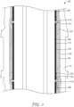
- FIG. 1 shows a first aspect of the invention, voltage sensor 100.
- Voltage sensor 100 includes a conductor (also referred to as an inner conductor) 102, which may be a solid or stranded metal axial conductor such as an aluminum or copper alloy conductor.
- Inner conductor 102 includes a first end 101, which can include a first connection interface 150 and a second end 103.
- the second end 103 has no connection.
- the second end is shaped to allow for optimal stress control in a minimal space with ease, to substantially reduce the probability of partial discharge or electrical failure.
- second end 103 includes a rounded surface 105, such as a fully rounded surface (i.e., having no or almost no sharp edges). This rounded surface shape reduces electric field stress concentration.
- a conductor also referred to as an inner conductor
- Inner conductor 102 includes a first end 101, which can include a first connection interface 150 and a second end 103.
- the second end 103 has no connection.
- the second end is shaped to allow for optimal stress control in a minimal space with ease, to
- the rounded surface 105 has a bulbous shape.
- a bulbous end can be omitted.
- a full radius can be formed from the end 103 of the conductor. This semi-hemispherical shape would also remove any sharp edges that can lead to electric stress concentrations.
- the second end 103 of the voltage sensor 100 can be covered with a molded semiconducting rubber or semiconducting plastic material.
- the semiconducting molding can be used to cover a rounded surface or a sharp surface.
- the first connection interface 150 can include a lug, which is shown in Fig. 1 .
- the connection interface can comprise a separable connector, a splice, a modular connector, or other connection interfaces.
- connection interface can have a circular cross section configured to mate to a male end of conductor 102.
- first end of the conductor 102 can be formed as a male or hybrid type connector.
- connection interface 150 comprises a lug.
- the structure of Fig. 1 allows for straightforward mechanical fastening and electrical conduction (or path) from an overhead power cable or line.
- one method of attaching the voltage sensor 100 to an overhead line is to use a conventional overhead primary tap (such as a BHF/AHF two hole hot line pad connector available from Hubbell Power Systems, USA) and bolt that connector to connection interface/lug 150.
- a conventional stem connector can be used.
- voltage sensor 100 can be installed at any point along a power cable, line or in a cable accessory.
- voltage sensor 100 is configured to control the electrical field created by medium or high voltage within a power line or cable, such as an overhead power line or cable, wherein the power line or cable operates at voltages in excess of 1,000 Volts.
- a high K layer 132 can be employed to control the electric field.
- voltage sensor 100 can include geometric stress control (not shown).
- inner conductor 102 may be radially surrounded by conductor shield layer 104.
- Conductor shield layer 104 comprises a conductive or semi-conductive material that is configured to smooth out any conductor surface inconsistencies that could create high electric field stress concentrations, especially when sensing the voltage of a medium or high voltage line or cable, which could cause a reduction in accuracy or possible sensor failure.
- the outer surface of the conductor shield layer 104 is smooth.
- the inner conductor 102 and optional inner shield layer 104 provide one electrode of a capacitor for the sensor section. The other electrode of the capacitor is formed by the isolated section 110 of insulation shield layer 108, and insulation layer(s) 106 serves as the dielectric of the capacitor.
- Voltage sensor 100 further includes insulation layer 106, which concentrically surrounds conductor shield layer 104.
- the insulation layer 106 can be formed from a conventional dielectric material, such as elastomeric silicone, ethylene propylene diene monomer rubber (EPDM), hybrids or combinations thereof.
- insulation layer 106 can comprise more than 1 layer of insulation material, such as first and second insulation layers (not shown), with each layer being formed from a different or same insulation material.
- the optional semi-conductive or conductive shield layer 104 functions to eliminate or reduce the potential for voids between conductor 102 and insulation layer(s) 106 that might allow leakage leading to degradation of insulation layer(s) 106.
- Shield layer 104 may also relieve electrical stresses caused by any roughness on the surface of the inner conductor 102 due to, for example, manufacturing processes such as casting.
- conductive layer 102 can have a highly smooth outer surface.
- an adhesive or other bonding material can be interposed between the conductive layer 102 and the insulation layer 106, with the shield layer 104 being omitted.
- the adhesive or other bonding material can be applied to the outer surface of conductor 102 and can bond the insulation layer 106 to the conductive layer 102.
- an insulation shield layer 108 is provided and concentrically surrounds insulation layer 106.
- the insulation shield layer 108 comprises a conductive or semiconductive material formed as a layer adjacent to and concentrically surrounding insulation layer 106.
- this insulation layer 106 also forms the insulation layer of a capacitor, which also comprises the inner conductor 102 and/or conductor shield layer 104 and isolated section 110 of insulation shield layer 108. Isolated section of insulation shield layer 110 is isolated from the ground potential of the remainder of insulation shield layer 108.
- voltage sensor 100 further comprises a tubular sleeve 112 that extends over at least a portion of the conductor/inner shield/insulation/shield structure and the sensor section 125.
- tubular sleeve 112 comprises a suitable cold-shrinkable material, such as a highly elastic rubber material that has a low permanent set, such as EPDM, elastomeric silicone, electrical grade resin, or a hybrid thereof.
- Insulation layer 106 and tubular sleeve can be made of the same or different types of materials.
- the semi-conductive and insulating materials may have differing degrees of conductivity and insulation based on the inherent properties of the materials used or based on additives added to the materials.
- Tubular sleeve 112 may also be made from a suitable heat-shrinkable material. Alternatively, the tubular sleeve 112 may be an overmolded or push-on layer. A ground reference wire 115 can also be provided. Optionally, in the illustrated embodiment, tubular sleeve 112 includes skirts 135 which serve to reduce leakage current and which is particularly useful for outdoor applications. In some embodiments, tubular sleeve 112 can also cover rounded end 103.
- a sealing compound 130 can be provided to create an environmental seal and prevent moisture from migrating into the area between the insulation layer 106 and the connection interface/lug 150.
- voltage sensor 100 includes a sensor section 125 disposed between the first and second ends of conductor 102.
- the sensing section includes a voltage sensor, such as an impedance voltage divider that utilizes complex impedance based voltage division, or a capacitive voltage sensing device, having an electrically isolated capacitive voltage sensor. More generally, in at least one aspect, where the sensing section includes an impedance voltage divider, a first impedance and a second impedance are connected in series. The input voltage is applied across the series impedances and the output voltage is the voltage across the second impedance.
- the first and second impedances may be composed of any combination of elements such as resistors, inductors and capacitors.
- the sensing section includes a multi-component AC circuit, wherein the response can be complex and can have imaginary components.
- the sensor section includes at least one temperature compensation component, such as, e.g., a thermistor.
- the temperature sensor e.g., thermistor
- the sensing section can also be configured in a manner similar to the voltage sensors described in International Publ. Nos. WO 2015/179285 and WO 2013/096354 , each incorporated by reference herein in their entirety.
- the voltage sensor 100 can further include one or more additional sensors.
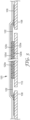
- the sensing section 125 includes an electrically isolated section 110 of conductive or semiconductive material (insulation shield) layer 108 in contact with an outer surface of insulation layer 106.
- the electrically isolated section 110 of conductive or semiconductive material (insulation shield) layer 108 forms an electrode of a sensing capacitor of a capacitive voltage divider or sensor.
- the electrically isolated section thus can be capacitively coupled to the conductor 102 and electrically isolated from ground potential.
- insulation layer 106 is operable to form a dielectric of the sensing capacitor of the capacitive voltage divider or sensor.
- the electrically isolated section 110 may be in an annular ring configuration and be electrically isolated from conductive or semiconductive shielding layer 108 by non-conductive axial sections 111a and 111b.
- Non-conductive axial sections 111a, 111b may comprise non-conductive material or a void.
- conductive or semiconductive shielding layer 108 may be discontinuous at two longitudinal positions to form electrically isolated section 110 in the annular ring configuration.
- electrically isolated section 110 may be formed out of a common material and manufacturing process, such that electrically isolated section 110 and shield layer 108 have a common thickness.
- electrically isolated section 110 may be formed from a different material than shield layer 108 and/or have a different configuration such as a rectangular or round shape formed by a flexible material affixed to insulation layer 106. Electrically isolated section 110 may, for example, comprise an electrically conductive metal or an electrically conductive polymer. As one example, electrically isolated section 110 may comprise a layer of copper. In some examples, voltage sensor 100 may include an adhesive that affixes electrically isolated section 110 to insulation layer 106. In some examples, electrically isolated section 110 may further include a conforming rubber insulation or high dielectric constant tape or a self-fusing insulation or high K material 127, such as a rubber mastic material, to prevent moisture from migrating into the sensor section 125.
- strips of insulating or high dielectric constant material cover gaps 111a, 111b to separate isolated section 110 from any other conductive or semiconductive material or elements, except from the PCB 120, and to prevent the presence of air in gaps 111a, 11 1b, which air could cause a partial electrical discharge and a failure of the voltage sensor.
- the insulating or high dielectric constant material may be any suitable material such as a combination of mastic, which will more easily fill gaps 111a, 111b, and PVC tape placed over the mastic.
- the electrically isolated section 110 may include a heat shrinkable or cold shrinkable material.
- inner and outer conductive or semiconductive shield layers 104, 108 and insulating layer 106 of voltage sensor 100 may be made from any materials suitable for shrinkable sleeve applications. Most suitable are materials such as a highly elastic rubber material that has a low permanent set, such as ethylene propylene diene monomer (EPDM), elastomeric silicone, or a hybrid thereof, that may include conventional additives to make the layers appropriately conductive, semiconductive or insulating, as needed.
- EPDM ethylene propylene diene monomer
- the conductive or semiconductive shield layers and the insulation layer may be made of the same or different types of materials, depending on the types of additives which may be incorporated in the individual layers.
- the inner and outer conductive or semiconductive shield layers and the insulation layer may have differing degrees of conductivity and insulation based on the inherent properties of the materials used or based on additives added to the materials.
- the sensor section 125 is configured as a capacitive voltage sensor, which is operable to sense a voltage on inner conductor 102, which is also representative of the voltage on the power line (not shown) by way of the connection with the connection interface 150.
- Electrically isolated section 110 is operable to form an electrode of the sensing capacitor of the capacitive voltage sensor and may, for example, have two opposed major surfaces, e.g. first and second major surfaces.
- the first major surface may be in mechanical contact with insulation layer 106.
- the second major surface may be in mechanical contact with a capacitive element, such as a capacitor, circuitry, or a printed circuit board (PCB) 120.
- the capacitive element, such as PCB 120 has a pre-defined capacitance value.
- the output of the voltage sensor can be a waveform that is directly proportional to the voltage of the power line.
- the division ratio of the actual line voltage to the output voltage can be tailored to any desired voltage. In some embodiments, the division ratio can be between 1:1 and 1,000,000:1; in other aspects, the division ratio can be approximately 10,000:1, where for example an actual line voltage of approximately 10,000 Volts would result in an output voltage of approximately 1 Volt.
- the voltage sensor 100 supplies a voltage level that can in some embodiments be easily converted to a digital value for interaction with computational devices, microcontrollers, communication devices, etc.
- the capacitive voltage sensor further includes capacitive element (here PCB 120), which is in electrical contact with electrically isolated section 110.
- the PCB 120 is located directly over the electrically isolated section 110 to arrange for the electrical contact with the isolated section 110, which in turn is arranged on insulation layer 106.
- PCB 120 further includes at least one additional capacitor or other capacitive element to form a capacitive voltage divider for determining the voltage of inner conductor 102 by way of the detected voltage of electrically isolated section 110.
- the capacitor(s) of PCB 120 may be electrically connected to electrically isolated section 110.
- the capacitive element may be operable as a secondary capacitor in a capacitive voltage divider.
- the capacitive voltage divider may comprise the sensing capacitor, which includes electrically isolated section 110, and the secondary capacitor.
- PCB 120 may be flexible such that PCB 120 may be bent to conform around electrically isolated section 110.
- PCB 120 may establish electrical contact to electrically isolated section 110 in several locations. This construction avoids the disadvantages of having electrical contact only in one location on electrically isolated section 110, such as, problems resulting from a bad electrical contact in the one location, if that one contact is, e.g., incomplete, corroded, or damaged, which might preclude a voltage reading.
- providing multiple points of contact may avoids problems arising from the fact that electrons travelling from a rim of electrically isolated section 110 to a single contact location experience the electrical resistance of electrically isolated section 110 over a longer path. This, in turn, may lead to a voltage drop and eventually to a lower, i.e. less accurate, voltage being measured on PCB 120.
- PCB 120 may be mechanically attached to electrically isolated section 110. In other examples, PCB 120 may alternatively be in a pressure contact with electrically isolated section 110.
- PCB 120 may comprise a double-sided PCB, i.e. PCB 120 can have opposed first and second major sides. Alternatively the PCB 120 can be located remotely from the isolated section 110, where the PCB 120 can be electrically coupled to the isolated section 110.
- PCB 120 can comprise a multilayer structure, with a first layer 120a comprising a conductive metal, e.g. gold, silver, or copper; a second layer 120b comprising a flexible insulation material; a third layer or conductive trace 120c to connect to jumper wires 122; a fourth layer 120d comprising an outer insulation layer; and an outer conductive shield layer 120e comprising a conductive or semiconductive layer which shields PCB 120.
- a conductive metal e.g. gold, silver, or copper
- second layer 120b comprising a flexible insulation material
- a third layer or conductive trace 120c to connect to jumper wires 122
- fourth layer 120d comprising an outer insulation layer
- an outer conductive shield layer 120e comprising a conductive or semiconductive layer which shields PCB 120.
- first layer 120a can comprise a copper layer that may be gold-plated for enhanced electrical contact and/or for protection against environmental influences, e.g. against corrosion.
- first PCB layer 120a comprises a conductive region that provides a continuous surface contact area or a patterned, i.e. interrupted, non-continuous, surface contact area for contact with electrically isolated section 110. All parts of the patterned surface contact area may be electrically connected with each other. A patterned surface contact area may require less conductive material for manufacturing it, while having only a negligible influence on reliability of the electrical contact and resistive losses.
- PCB 120 may comprise a flexible portion.
- a patterned surface contact area may also enhance the mechanical flexibility of PCB 120, thus reducing the risk of layer cracking and/or flaking, when PCB 120 is bent.
- the first PCB layer 120a comprises a patterned gold-plated copper layer.
- a pattern of the surface contact area may, for example, be a grid with a square-shaped or a diamond-shaped pattern.
- the PCB 120 may further comprise a second layer 120b comprising a flexible insulating material, such as a conventional, flexible insulation material.
- a flexible portion of PCB 120 and in particular a flexible PCB may allow PCB 120 to conform better to electrically isolated section 110. This, in turn, enhances the electrical contact between PCB 120 and electrically isolated section 110 and thereby makes the contact more reliable, reduces resistive losses, and facilitates higher accuracy of the voltage sensor.
- a conductive trace 120c connects with jumper wires 122, which are connected to ground on either side of the isolated section 110 by conductive tape/adhesive 109 disposed on shield layer 108.
- the conductive tape/adhesive 109 provides adequate surface area.
- the outer shield layer 120e can comprise a conductive or semiconductive material and is grounded to conductive tape/adhesive 109, as shown in Fig. 3 .
- PCB 120 may further include a plurality of ratio adjustment capacitors.
- PCB 120 may generate a signal that is indicative of the voltage of inner conductor 102.
- Sensor signal wire 124 can be connected to PCB 120 for transmitting the sensor voltage signal from PCB 120.
- electrical measurement circuitry may be incorporated into the PCB 120; in other examples, PCB 120 may include electrical measurement circuitry.
- Sensor signal wire 124 they may be connected to, for example, a remote terminal unit that processes voltage data from the sensor section 125, or an integrator, a measuring device, a control device, or other suitable types of devices.
- a ground reference wire 122 may be used to bring ground onto PCB 120 for connecting electrical ground to the electrical measurement circuitry.
- ground reference wire 122 is connected to a conductive trace of PCB 120, such as conductive trace 120c shown in Fig. 3 . This configuration brings a bridging connection between the insulation shield layers on either side of isolated section 110.
- the electric measurement circuitry may be operational to determine the voltage of inner conductor 102 versus ground.
- PCB 120 may be adapted to support additional sensing such as temperature, humidity, magnetic field, etc.
- PCB 120 can be directly disposed on insulation layer 106, such that the isolated section 110 of the shielding layer 108 can be eliminated. In a further alternative aspect, PCB 120 can be disposed directly on insulation layer 106 at a position beyond an end of the shielding layer 108.
- the sensor section 125 further includes a sensor insulation layer 126 that is disposed adjacent to the isolated section 110.
- the sensor insulation layer 126 can be adjacent to the PCB 120 and on the opposing side of PCB 120 relative to electrically isolated section 110. The sensor insulation layer 126 helps to prevent the PCB 120 from shorting out.
- the sensor section 125 further includes a sensor (outer) shielding layer 128 that is disposed adjacent to sensor insulation layer 126 on the opposing side of sensor insulation layer 126 relative to PCB 120.
- Outer sensor shield layer 128 may be formed from a conductive or semiconductive material and may be electrically connected to shield layer 108, e.g., at ground potential.
- Outer sensor shield layer 128 provides electric field shielding to contain the electric field from the isolated section 110/outer electrode and from external electric fields.
- Outer sensor shield layer 128 and insulation shield layer 108 may function to substantially encapsulate the capacitive voltage sensor, including the electrically isolated section 110, PCB 120 and sensor insulation layer 126.
- outer sensor shield layer 128 and insulation shield layer 108 may be formed as a unitary feature.
- tubular sleeve 112 extends over at least a portion of the sensor section 125.
- the precise dimensional control facilitated by the design and configuration of voltage sensor 100 allows for precise voltage measurements by the capacitive voltage sensor of the sensor section 125.
- capacitance is directly related to the geometry of two conductive electrodes and the insulation forming the capacitor.
- the sensing capacitor is formed from inner conductor 102/inner shield layer 104, insulation layer 106 and electrically isolated section 110.
- voltage sensor 100 may be formed using overmolded construction.
- inner shield layer 104 may be overmolded on inner conductor 102.
- insulation layer 106 may be an overmolded insulation layer overmolded on inner shield layer 104 or overmolded directly on inner conductor 102 if inner shield layer 104 is not included in the voltage sensor device 100.
- shield layer 108 may be an overmolded outer conductive or semiconductive layer overmolded on insulation layer 106.
- the construction can comprise a multilayer body that can be formed as a contiguous overmolded body that comprises the insulation layer 106, shield layer 108, the isolated section 110, and optionally the inner shield layer 104.
- the voltage ratio of the sensing section 125 can be adjusted by varying the length of the isolated section 110 or, in an alternative aspect, by varying the length of the PCB 120 that replaces isolated section 110.
- RTV, grease, mastic, or other insulating or high dielectric constant materials can be applied to eliminate air gaps/voids between the PCB 120 and the cable insulation 106 and/or to eliminate corona discharges.
- the voltage sensor described herein can be utilized in a variety of applications.
- the voltage sensor can be deployed on any section of the power grid having a voltage, such as with standard medium or high voltage cable, bus bars, capacitor banks, connectors, lugs, jumpers, any component used in a power grid, switches, and switch gear.
- the voltage sensor can be used in underground equipment applications such as pad mounted transclosures, pad mounted primary metering cabinets, and many live front pad mounted or vault-type live front applications.
- the voltage sensor can also be used in switch gear applications, where the gear is considered deadfront underground equipment.
Landscapes
- Physics & Mathematics (AREA)
- General Physics & Mathematics (AREA)
- Measuring Instrument Details And Bridges, And Automatic Balancing Devices (AREA)
Applications Claiming Priority (2)
| Application Number | Priority Date | Filing Date | Title |
|---|---|---|---|
| US201562162910P | 2015-05-18 | 2015-05-18 | |
| PCT/US2016/032630 WO2016187090A1 (en) | 2015-05-18 | 2016-05-16 | Voltage sensor |
Publications (2)
| Publication Number | Publication Date |
|---|---|
| EP3298417A1 EP3298417A1 (en) | 2018-03-28 |
| EP3298417B1 true EP3298417B1 (en) | 2024-10-23 |
Family
ID=56409674
Family Applications (1)
| Application Number | Title | Priority Date | Filing Date |
|---|---|---|---|
| EP16738575.6A Active EP3298417B1 (en) | 2015-05-18 | 2016-05-16 | Voltage sensor using a capacitive voltage divider |
Country Status (8)
| Country | Link |
|---|---|
| US (1) | US10761117B2 (enExample) |
| EP (1) | EP3298417B1 (enExample) |
| JP (1) | JP2018514787A (enExample) |
| CN (1) | CN107636477A (enExample) |
| BR (1) | BR112017024892A2 (enExample) |
| CA (1) | CA2986387A1 (enExample) |
| TW (1) | TW201708827A (enExample) |
| WO (1) | WO2016187090A1 (enExample) |
Cited By (1)
| Publication number | Priority date | Publication date | Assignee | Title |
|---|---|---|---|---|
| US20250004016A1 (en) * | 2021-06-04 | 2025-01-02 | 3M Innovative Properties Company | Sensored insulation plug with detection contact |
Families Citing this family (19)
| Publication number | Priority date | Publication date | Assignee | Title |
|---|---|---|---|---|
| IT201600103234A1 (it) | 2016-10-14 | 2018-04-14 | Green Seas Ventures Ldt | Sistema Costruttivo afferente un sensore capacitivo di tensione |
| EP3415929B1 (en) | 2017-06-13 | 2022-08-03 | Nexans | Electrical accessory comprising a sensing element of voltage on a cable |
| TWI632378B (zh) * | 2017-09-07 | 2018-08-11 | 新唐科技股份有限公司 | 低功耗電壓偵測電路 |
| EP3486662B1 (en) * | 2017-11-20 | 2022-08-10 | 3M Innovative Properties Company | Voltage divider assembly |
| IT201800004114A1 (it) | 2018-03-30 | 2019-09-30 | Green Seas Ventures Ltd C/O Citco B V I Ltd | Sistema costruttivo afferente un sensore capacitivo di tensione |
| WO2020055666A1 (en) * | 2018-09-10 | 2020-03-19 | 3M Innovative Properties Company | Electrical power cable monitoring device using low side electrode and earth ground separation |
| WO2020055662A1 (en) | 2018-09-10 | 2020-03-19 | 3M Innovative Properties Company | Support structure for cable and cable accessory condition monitoring devices |
| CN112867930B (zh) | 2018-09-10 | 2025-03-18 | 3M创新有限公司 | 包括局部放电传感器的电力电缆监测装置 |
| EP3884284A1 (en) * | 2018-11-20 | 2021-09-29 | 3M Innovative Properties Company | End plug sensor device with voltage divider and test point features |
| WO2020131903A1 (en) | 2018-12-17 | 2020-06-25 | G & W Electric Company | Electrical sensor assembly |
| EP3899557A4 (en) | 2018-12-17 | 2022-10-26 | G & W Electric Company | ELECTRIC DETECTOR ASSEMBLY |
| CN113574755B (zh) | 2018-12-21 | 2023-06-13 | 3M创新有限公司 | 电缆制备系统 |
| EP3900135A1 (en) | 2018-12-21 | 2021-10-27 | 3M Innovative Properties Company | Electrical power cable preparation device |
| CN109991463A (zh) * | 2019-04-19 | 2019-07-09 | 河北润志电气设备有限公司 | 一种交流电压传感器 |
| EP3840135B1 (en) * | 2019-12-20 | 2023-09-13 | 3M Innovative Properties Company | Retrofittable voltage sensing device for power networks |
| WO2021133516A1 (en) | 2019-12-26 | 2021-07-01 | 3M Innovative Properties Company | Automated cable preparation with modular system |
| WO2021138573A1 (en) | 2019-12-31 | 2021-07-08 | 3M Innovative Properties Company | Local partial discharge monitoring |
| IT202000003128A1 (it) * | 2020-02-17 | 2021-08-17 | Eb Rebosio S R L | Elemento multistrato per applicazioni elettrotecniche |
| DE102020212375A1 (de) * | 2020-09-30 | 2022-03-31 | Siemens Aktiengesellschaft | Anschluss für eine Feldsondenkombination |
Family Cites Families (24)
| Publication number | Priority date | Publication date | Assignee | Title |
|---|---|---|---|---|
| DE2413927C3 (de) | 1974-03-20 | 1987-10-22 | Siemens AG, 1000 Berlin und 8000 München | Anordnung mit einem Hochspannungskondensator |
| DE2460717C3 (de) * | 1974-12-19 | 1980-08-14 | Siemens Ag, 1000 Berlin Und 8000 Muenchen | Spannungs-Meßeinrichtung mit einem kapazitiven Spannungsteiler für eine vollisolierte, metallgekapselte Hochspannungsschaltanlage |
| DE3129901A1 (de) * | 1981-07-24 | 1983-02-10 | Siemens AG, 1000 Berlin und 8000 München | Hochspannungsmesseinrichtung mit einem kapazitiven teiler in einem mit isoliergas gefuellten behaelter |
| CA1277371C (en) * | 1984-07-02 | 1990-12-04 | Graham J. Clarke | High voltage apparatus |
| US6538422B2 (en) | 2000-04-26 | 2003-03-25 | S & C Electric Co. | Voltage sensor bushing assembly with integral capacitance screen |
| DE10056988A1 (de) * | 2000-11-17 | 2002-05-23 | Kg Ritz Messwandler G M B H & | Spannungsteileranordnung |
| DE102004013606B4 (de) | 2004-03-18 | 2012-07-26 | Sikora Ag | Vorrichtung zur Messung von Störungen oder Unterbrechungen in der inneren Glättungsschicht in Mittel- und Hochspannungskabeln |
| JP2007205785A (ja) * | 2006-01-31 | 2007-08-16 | Energy Support Corp | 電力機器の電圧測定装置 |
| CN1908681B (zh) * | 2006-08-15 | 2010-04-07 | 重庆大学 | 一种交流电力系统过电压监测传感器 |
| ITBO20080084U1 (it) * | 2008-11-18 | 2010-05-19 | Lorenzo Peretto | Sistema costruttivo per sensore di corrente e/o di tensione elettrica |
| JP2010127725A (ja) * | 2008-11-27 | 2010-06-10 | Hioki Ee Corp | 非接触電圧測定装置および非接触電圧測定方法 |
| CN101566640B (zh) * | 2009-06-09 | 2011-05-18 | 三峡大学 | 一种电子式电压传感器 |
| US8294477B2 (en) * | 2009-11-20 | 2012-10-23 | Smc Electrical Products, Inc. | High voltage sensing capacitor and indicator device |
| US8493056B2 (en) * | 2010-05-12 | 2013-07-23 | Broadcom Corporation | AC voltage measurement circuit |
| DK2461026T4 (en) * | 2010-12-03 | 2017-03-13 | Siemens Ag | Device and method for testing a system for producing electricity |
| EP2479581A1 (en) * | 2011-01-21 | 2012-07-25 | PowerSense A/S | An AC or DC power transmission system and a method of measuring a voltage |
| JP6050309B2 (ja) | 2011-03-25 | 2016-12-21 | イアンディスEandis | 高電圧測定システム |
| JP2012242331A (ja) * | 2011-05-23 | 2012-12-10 | Mitsubishi Electric Corp | 振幅制御電圧センサ |
| WO2013038176A2 (en) * | 2011-09-12 | 2013-03-21 | Metroic Limited | Current measurement |
| PL2608338T3 (pl) | 2011-12-21 | 2014-04-30 | 3M Innovative Properties Co | Urządzenie do łączenia końcówki kabla energetycznego |
| US9198500B2 (en) * | 2012-12-21 | 2015-12-01 | Murray W. Davis | Portable self powered line mountable electric power line and environment parameter monitoring transmitting and receiving system |
| CN103901258A (zh) * | 2014-04-09 | 2014-07-02 | 福建鑫恒源智能电气有限公司 | 一种支撑绝缘子式的感应高压传感器 |
| ES2924426T3 (es) | 2014-05-19 | 2022-10-06 | 3M Innovative Properties Co | Puente eléctrico sensorizado |
| US9442138B2 (en) * | 2014-08-05 | 2016-09-13 | Southern States, Llc | High voltage sensor located within line insulator |
-
2016
- 2016-05-16 JP JP2017559801A patent/JP2018514787A/ja active Pending
- 2016-05-16 WO PCT/US2016/032630 patent/WO2016187090A1/en not_active Ceased
- 2016-05-16 US US15/573,889 patent/US10761117B2/en active Active
- 2016-05-16 CA CA2986387A patent/CA2986387A1/en not_active Abandoned
- 2016-05-16 EP EP16738575.6A patent/EP3298417B1/en active Active
- 2016-05-16 BR BR112017024892A patent/BR112017024892A2/pt not_active Application Discontinuation
- 2016-05-16 CN CN201680028749.4A patent/CN107636477A/zh active Pending
- 2016-05-17 TW TW105115207A patent/TW201708827A/zh unknown
Cited By (1)
| Publication number | Priority date | Publication date | Assignee | Title |
|---|---|---|---|---|
| US20250004016A1 (en) * | 2021-06-04 | 2025-01-02 | 3M Innovative Properties Company | Sensored insulation plug with detection contact |
Also Published As
| Publication number | Publication date |
|---|---|
| CA2986387A1 (en) | 2016-11-24 |
| CN107636477A (zh) | 2018-01-26 |
| EP3298417A1 (en) | 2018-03-28 |
| TW201708827A (zh) | 2017-03-01 |
| US10761117B2 (en) | 2020-09-01 |
| WO2016187090A1 (en) | 2016-11-24 |
| BR112017024892A2 (pt) | 2018-07-31 |
| US20180292435A1 (en) | 2018-10-11 |
| JP2018514787A (ja) | 2018-06-07 |
Similar Documents
| Publication | Publication Date | Title |
|---|---|---|
| EP3298417B1 (en) | Voltage sensor using a capacitive voltage divider | |
| US9742180B2 (en) | Power cable terminal connection device | |
| EP2806277B1 (en) | Closure | |
| EP3198696B1 (en) | Cable terminal and termination with an integrated monitoring device | |
| EP2816361B1 (en) | Conductor assembly | |
| EP3146598B1 (en) | Sensored electrical jumper | |
| EP3236272B1 (en) | High-voltage lead-in insulating device | |
| WO2019229694A1 (en) | Voltage sensor |
Legal Events
| Date | Code | Title | Description |
|---|---|---|---|
| STAA | Information on the status of an ep patent application or granted ep patent |
Free format text: STATUS: THE INTERNATIONAL PUBLICATION HAS BEEN MADE |
|
| PUAI | Public reference made under article 153(3) epc to a published international application that has entered the european phase |
Free format text: ORIGINAL CODE: 0009012 |
|
| STAA | Information on the status of an ep patent application or granted ep patent |
Free format text: STATUS: REQUEST FOR EXAMINATION WAS MADE |
|
| 17P | Request for examination filed |
Effective date: 20171121 |
|
| AK | Designated contracting states |
Kind code of ref document: A1 Designated state(s): AL AT BE BG CH CY CZ DE DK EE ES FI FR GB GR HR HU IE IS IT LI LT LU LV MC MK MT NL NO PL PT RO RS SE SI SK SM TR |
|
| AX | Request for extension of the european patent |
Extension state: BA ME |
|
| DAV | Request for validation of the european patent (deleted) | ||
| DAX | Request for extension of the european patent (deleted) | ||
| STAA | Information on the status of an ep patent application or granted ep patent |
Free format text: STATUS: EXAMINATION IS IN PROGRESS |
|
| 17Q | First examination report despatched |
Effective date: 20200629 |
|
| GRAP | Despatch of communication of intention to grant a patent |
Free format text: ORIGINAL CODE: EPIDOSNIGR1 |
|
| STAA | Information on the status of an ep patent application or granted ep patent |
Free format text: STATUS: GRANT OF PATENT IS INTENDED |
|
| INTG | Intention to grant announced |
Effective date: 20240729 |
|
| GRAS | Grant fee paid |
Free format text: ORIGINAL CODE: EPIDOSNIGR3 |
|
| GRAA | (expected) grant |
Free format text: ORIGINAL CODE: 0009210 |
|
| STAA | Information on the status of an ep patent application or granted ep patent |
Free format text: STATUS: THE PATENT HAS BEEN GRANTED |
|
| AK | Designated contracting states |
Kind code of ref document: B1 Designated state(s): AL AT BE BG CH CY CZ DE DK EE ES FI FR GB GR HR HU IE IS IT LI LT LU LV MC MK MT NL NO PL PT RO RS SE SI SK SM TR |
|
| REG | Reference to a national code |
Ref country code: GB Ref legal event code: FG4D |
|
| REG | Reference to a national code |
Ref country code: CH Ref legal event code: EP |
|
| REG | Reference to a national code |
Ref country code: DE Ref legal event code: R096 Ref document number: 602016089935 Country of ref document: DE |
|
| P01 | Opt-out of the competence of the unified patent court (upc) registered |
Free format text: CASE NUMBER: APP_55974/2024 Effective date: 20241011 |
|
| REG | Reference to a national code |
Ref country code: IE Ref legal event code: FG4D |
|
| REG | Reference to a national code |
Ref country code: LT Ref legal event code: MG9D |
|
| REG | Reference to a national code |
Ref country code: NL Ref legal event code: MP Effective date: 20241023 |
|
| REG | Reference to a national code |
Ref country code: AT Ref legal event code: MK05 Ref document number: 1735250 Country of ref document: AT Kind code of ref document: T Effective date: 20241023 |
|
| PG25 | Lapsed in a contracting state [announced via postgrant information from national office to epo] |
Ref country code: NL Free format text: LAPSE BECAUSE OF FAILURE TO SUBMIT A TRANSLATION OF THE DESCRIPTION OR TO PAY THE FEE WITHIN THE PRESCRIBED TIME-LIMIT Effective date: 20241023 |
|
| PG25 | Lapsed in a contracting state [announced via postgrant information from national office to epo] |
Ref country code: NL Free format text: LAPSE BECAUSE OF FAILURE TO SUBMIT A TRANSLATION OF THE DESCRIPTION OR TO PAY THE FEE WITHIN THE PRESCRIBED TIME-LIMIT Effective date: 20241023 |
|
| PG25 | Lapsed in a contracting state [announced via postgrant information from national office to epo] |
Ref country code: IS Free format text: LAPSE BECAUSE OF FAILURE TO SUBMIT A TRANSLATION OF THE DESCRIPTION OR TO PAY THE FEE WITHIN THE PRESCRIBED TIME-LIMIT Effective date: 20250223 Ref country code: PT Free format text: LAPSE BECAUSE OF FAILURE TO SUBMIT A TRANSLATION OF THE DESCRIPTION OR TO PAY THE FEE WITHIN THE PRESCRIBED TIME-LIMIT Effective date: 20250224 Ref country code: HR Free format text: LAPSE BECAUSE OF FAILURE TO SUBMIT A TRANSLATION OF THE DESCRIPTION OR TO PAY THE FEE WITHIN THE PRESCRIBED TIME-LIMIT Effective date: 20241023 |
|
| PG25 | Lapsed in a contracting state [announced via postgrant information from national office to epo] |
Ref country code: FI Free format text: LAPSE BECAUSE OF FAILURE TO SUBMIT A TRANSLATION OF THE DESCRIPTION OR TO PAY THE FEE WITHIN THE PRESCRIBED TIME-LIMIT Effective date: 20241023 |
|
| PG25 | Lapsed in a contracting state [announced via postgrant information from national office to epo] |
Ref country code: BG Free format text: LAPSE BECAUSE OF FAILURE TO SUBMIT A TRANSLATION OF THE DESCRIPTION OR TO PAY THE FEE WITHIN THE PRESCRIBED TIME-LIMIT Effective date: 20241023 |
|
| PG25 | Lapsed in a contracting state [announced via postgrant information from national office to epo] |
Ref country code: ES Free format text: LAPSE BECAUSE OF FAILURE TO SUBMIT A TRANSLATION OF THE DESCRIPTION OR TO PAY THE FEE WITHIN THE PRESCRIBED TIME-LIMIT Effective date: 20241023 |
|
| PG25 | Lapsed in a contracting state [announced via postgrant information from national office to epo] |
Ref country code: NO Free format text: LAPSE BECAUSE OF FAILURE TO SUBMIT A TRANSLATION OF THE DESCRIPTION OR TO PAY THE FEE WITHIN THE PRESCRIBED TIME-LIMIT Effective date: 20250123 |
|
| PG25 | Lapsed in a contracting state [announced via postgrant information from national office to epo] |
Ref country code: GR Free format text: LAPSE BECAUSE OF FAILURE TO SUBMIT A TRANSLATION OF THE DESCRIPTION OR TO PAY THE FEE WITHIN THE PRESCRIBED TIME-LIMIT Effective date: 20250124 Ref country code: AT Free format text: LAPSE BECAUSE OF FAILURE TO SUBMIT A TRANSLATION OF THE DESCRIPTION OR TO PAY THE FEE WITHIN THE PRESCRIBED TIME-LIMIT Effective date: 20241023 Ref country code: LV Free format text: LAPSE BECAUSE OF FAILURE TO SUBMIT A TRANSLATION OF THE DESCRIPTION OR TO PAY THE FEE WITHIN THE PRESCRIBED TIME-LIMIT Effective date: 20241023 |
|
| PG25 | Lapsed in a contracting state [announced via postgrant information from national office to epo] |
Ref country code: PL Free format text: LAPSE BECAUSE OF FAILURE TO SUBMIT A TRANSLATION OF THE DESCRIPTION OR TO PAY THE FEE WITHIN THE PRESCRIBED TIME-LIMIT Effective date: 20241023 |
|
| PG25 | Lapsed in a contracting state [announced via postgrant information from national office to epo] |
Ref country code: RS Free format text: LAPSE BECAUSE OF FAILURE TO SUBMIT A TRANSLATION OF THE DESCRIPTION OR TO PAY THE FEE WITHIN THE PRESCRIBED TIME-LIMIT Effective date: 20250123 |
|
| PG25 | Lapsed in a contracting state [announced via postgrant information from national office to epo] |
Ref country code: SM Free format text: LAPSE BECAUSE OF FAILURE TO SUBMIT A TRANSLATION OF THE DESCRIPTION OR TO PAY THE FEE WITHIN THE PRESCRIBED TIME-LIMIT Effective date: 20241023 |
|
| PGFP | Annual fee paid to national office [announced via postgrant information from national office to epo] |
Ref country code: DE Payment date: 20250423 Year of fee payment: 10 |
|
| PG25 | Lapsed in a contracting state [announced via postgrant information from national office to epo] |
Ref country code: DK Free format text: LAPSE BECAUSE OF FAILURE TO SUBMIT A TRANSLATION OF THE DESCRIPTION OR TO PAY THE FEE WITHIN THE PRESCRIBED TIME-LIMIT Effective date: 20241023 |
|
| PGFP | Annual fee paid to national office [announced via postgrant information from national office to epo] |
Ref country code: GB Payment date: 20250423 Year of fee payment: 10 |
|
| PGFP | Annual fee paid to national office [announced via postgrant information from national office to epo] |
Ref country code: IT Payment date: 20250423 Year of fee payment: 10 |
|
| PG25 | Lapsed in a contracting state [announced via postgrant information from national office to epo] |
Ref country code: EE Free format text: LAPSE BECAUSE OF FAILURE TO SUBMIT A TRANSLATION OF THE DESCRIPTION OR TO PAY THE FEE WITHIN THE PRESCRIBED TIME-LIMIT Effective date: 20241023 |
|
| PG25 | Lapsed in a contracting state [announced via postgrant information from national office to epo] |
Ref country code: RO Free format text: LAPSE BECAUSE OF FAILURE TO SUBMIT A TRANSLATION OF THE DESCRIPTION OR TO PAY THE FEE WITHIN THE PRESCRIBED TIME-LIMIT Effective date: 20241023 |
|
| REG | Reference to a national code |
Ref country code: DE Ref legal event code: R097 Ref document number: 602016089935 Country of ref document: DE |
|
| PG25 | Lapsed in a contracting state [announced via postgrant information from national office to epo] |
Ref country code: SK Free format text: LAPSE BECAUSE OF FAILURE TO SUBMIT A TRANSLATION OF THE DESCRIPTION OR TO PAY THE FEE WITHIN THE PRESCRIBED TIME-LIMIT Effective date: 20241023 |
|
| PG25 | Lapsed in a contracting state [announced via postgrant information from national office to epo] |
Ref country code: CZ Free format text: LAPSE BECAUSE OF FAILURE TO SUBMIT A TRANSLATION OF THE DESCRIPTION OR TO PAY THE FEE WITHIN THE PRESCRIBED TIME-LIMIT Effective date: 20241023 |
|
| PLBE | No opposition filed within time limit |
Free format text: ORIGINAL CODE: 0009261 |
|
| STAA | Information on the status of an ep patent application or granted ep patent |
Free format text: STATUS: NO OPPOSITION FILED WITHIN TIME LIMIT |
|
| PG25 | Lapsed in a contracting state [announced via postgrant information from national office to epo] |
Ref country code: SE Free format text: LAPSE BECAUSE OF FAILURE TO SUBMIT A TRANSLATION OF THE DESCRIPTION OR TO PAY THE FEE WITHIN THE PRESCRIBED TIME-LIMIT Effective date: 20241023 |
|
| 26N | No opposition filed |
Effective date: 20250724 |