EP3298293B2 - Bearing package and installation tool - Google Patents
Bearing package and installation tool Download PDFInfo
- Publication number
- EP3298293B2 EP3298293B2 EP16725709.6A EP16725709A EP3298293B2 EP 3298293 B2 EP3298293 B2 EP 3298293B2 EP 16725709 A EP16725709 A EP 16725709A EP 3298293 B2 EP3298293 B2 EP 3298293B2
- Authority
- EP
- European Patent Office
- Prior art keywords
- disc
- sleeve
- bearing assembly
- inner diameter
- axial
- Prior art date
- Legal status (The legal status is an assumption and is not a legal conclusion. Google has not performed a legal analysis and makes no representation as to the accuracy of the status listed.)
- Active
Links
- 238000009434 installation Methods 0.000 title description 4
- 238000003825 pressing Methods 0.000 claims description 15
- 238000000034 method Methods 0.000 claims description 10
- 238000005096 rolling process Methods 0.000 claims description 6
- 239000004033 plastic Substances 0.000 claims description 4
- 238000000926 separation method Methods 0.000 claims description 4
- 239000000463 material Substances 0.000 description 6
- 230000004323 axial length Effects 0.000 description 4
- 238000004806 packaging method and process Methods 0.000 description 3
- 239000000853 adhesive Substances 0.000 description 2
- 230000001070 adhesive effect Effects 0.000 description 2
- 230000008901 benefit Effects 0.000 description 2
- 239000002991 molded plastic Substances 0.000 description 2
- 230000000717 retained effect Effects 0.000 description 2
- 230000000712 assembly Effects 0.000 description 1
- 238000000429 assembly Methods 0.000 description 1
- 238000010276 construction Methods 0.000 description 1
- 230000003993 interaction Effects 0.000 description 1
- 239000002184 metal Substances 0.000 description 1
Images


Classifications
-
- F—MECHANICAL ENGINEERING; LIGHTING; HEATING; WEAPONS; BLASTING
- F16—ENGINEERING ELEMENTS AND UNITS; GENERAL MEASURES FOR PRODUCING AND MAINTAINING EFFECTIVE FUNCTIONING OF MACHINES OR INSTALLATIONS; THERMAL INSULATION IN GENERAL
- F16C—SHAFTS; FLEXIBLE SHAFTS; ELEMENTS OR CRANKSHAFT MECHANISMS; ROTARY BODIES OTHER THAN GEARING ELEMENTS; BEARINGS
- F16C35/00—Rigid support of bearing units; Housings, e.g. caps, covers
- F16C35/04—Rigid support of bearing units; Housings, e.g. caps, covers in the case of ball or roller bearings
- F16C35/06—Mounting or dismounting of ball or roller bearings; Fixing them onto shaft or in housing
- F16C35/067—Fixing them in a housing
-
- B—PERFORMING OPERATIONS; TRANSPORTING
- B25—HAND TOOLS; PORTABLE POWER-DRIVEN TOOLS; MANIPULATORS
- B25B—TOOLS OR BENCH DEVICES NOT OTHERWISE PROVIDED FOR, FOR FASTENING, CONNECTING, DISENGAGING OR HOLDING
- B25B27/00—Hand tools, specially adapted for fitting together or separating parts or objects whether or not involving some deformation, not otherwise provided for
- B25B27/02—Hand tools, specially adapted for fitting together or separating parts or objects whether or not involving some deformation, not otherwise provided for for connecting objects by press fit or detaching same
- B25B27/06—Hand tools, specially adapted for fitting together or separating parts or objects whether or not involving some deformation, not otherwise provided for for connecting objects by press fit or detaching same inserting or withdrawing sleeves or bearing races
-
- F—MECHANICAL ENGINEERING; LIGHTING; HEATING; WEAPONS; BLASTING
- F16—ENGINEERING ELEMENTS AND UNITS; GENERAL MEASURES FOR PRODUCING AND MAINTAINING EFFECTIVE FUNCTIONING OF MACHINES OR INSTALLATIONS; THERMAL INSULATION IN GENERAL
- F16C—SHAFTS; FLEXIBLE SHAFTS; ELEMENTS OR CRANKSHAFT MECHANISMS; ROTARY BODIES OTHER THAN GEARING ELEMENTS; BEARINGS
- F16C19/00—Bearings with rolling contact, for exclusively rotary movement
- F16C19/54—Systems consisting of a plurality of bearings with rolling friction
- F16C19/541—Systems consisting of juxtaposed rolling bearings including at least one angular contact bearing
- F16C19/542—Systems consisting of juxtaposed rolling bearings including at least one angular contact bearing with two rolling bearings with angular contact
- F16C19/543—Systems consisting of juxtaposed rolling bearings including at least one angular contact bearing with two rolling bearings with angular contact in O-arrangement
-
- F—MECHANICAL ENGINEERING; LIGHTING; HEATING; WEAPONS; BLASTING
- F16—ENGINEERING ELEMENTS AND UNITS; GENERAL MEASURES FOR PRODUCING AND MAINTAINING EFFECTIVE FUNCTIONING OF MACHINES OR INSTALLATIONS; THERMAL INSULATION IN GENERAL
- F16C—SHAFTS; FLEXIBLE SHAFTS; ELEMENTS OR CRANKSHAFT MECHANISMS; ROTARY BODIES OTHER THAN GEARING ELEMENTS; BEARINGS
- F16C41/00—Other accessories, e.g. devices integrated in the bearing not relating to the bearing function as such
- F16C41/04—Preventing damage to bearings during storage or transport thereof or when otherwise out of use
-
- F—MECHANICAL ENGINEERING; LIGHTING; HEATING; WEAPONS; BLASTING
- F16—ENGINEERING ELEMENTS AND UNITS; GENERAL MEASURES FOR PRODUCING AND MAINTAINING EFFECTIVE FUNCTIONING OF MACHINES OR INSTALLATIONS; THERMAL INSULATION IN GENERAL
- F16C—SHAFTS; FLEXIBLE SHAFTS; ELEMENTS OR CRANKSHAFT MECHANISMS; ROTARY BODIES OTHER THAN GEARING ELEMENTS; BEARINGS
- F16C43/00—Assembling bearings
- F16C43/04—Assembling rolling-contact bearings
-
- F—MECHANICAL ENGINEERING; LIGHTING; HEATING; WEAPONS; BLASTING
- F16—ENGINEERING ELEMENTS AND UNITS; GENERAL MEASURES FOR PRODUCING AND MAINTAINING EFFECTIVE FUNCTIONING OF MACHINES OR INSTALLATIONS; THERMAL INSULATION IN GENERAL
- F16C—SHAFTS; FLEXIBLE SHAFTS; ELEMENTS OR CRANKSHAFT MECHANISMS; ROTARY BODIES OTHER THAN GEARING ELEMENTS; BEARINGS
- F16C19/00—Bearings with rolling contact, for exclusively rotary movement
- F16C19/22—Bearings with rolling contact, for exclusively rotary movement with bearing rollers essentially of the same size in one or more circular rows, e.g. needle bearings
- F16C19/34—Bearings with rolling contact, for exclusively rotary movement with bearing rollers essentially of the same size in one or more circular rows, e.g. needle bearings for both radial and axial load
- F16C19/36—Bearings with rolling contact, for exclusively rotary movement with bearing rollers essentially of the same size in one or more circular rows, e.g. needle bearings for both radial and axial load with a single row of rollers
- F16C19/364—Bearings with rolling contact, for exclusively rotary movement with bearing rollers essentially of the same size in one or more circular rows, e.g. needle bearings for both radial and axial load with a single row of rollers with tapered rollers, i.e. rollers having essentially the shape of a truncated cone
-
- F—MECHANICAL ENGINEERING; LIGHTING; HEATING; WEAPONS; BLASTING
- F16—ENGINEERING ELEMENTS AND UNITS; GENERAL MEASURES FOR PRODUCING AND MAINTAINING EFFECTIVE FUNCTIONING OF MACHINES OR INSTALLATIONS; THERMAL INSULATION IN GENERAL
- F16C—SHAFTS; FLEXIBLE SHAFTS; ELEMENTS OR CRANKSHAFT MECHANISMS; ROTARY BODIES OTHER THAN GEARING ELEMENTS; BEARINGS
- F16C2326/00—Articles relating to transporting
- F16C2326/01—Parts of vehicles in general
- F16C2326/02—Wheel hubs or castors
Definitions
- the present invention relates to bearings, and more specifically to a device and method for packaging and installing a bearing.
- bearings that are not unitized or held together by their own components.
- some bearings include an inner ring, an outer ring, and a plurality of rolling elements between the inner and outer rings.
- the outer ring can move relative to the inner ring and roller assembly, resulting in potential seal and/or inner ring and/or cage damage.
- DE 102010038990 discloses a shaft bearing device in which a bearing is retained in a sleeve-like portion of an attachment unit by means of a disc-like support unit which connects to the attachment unit with a bayonet fixing to retain the bearing therebetween.
- the present invention provides a device for packaging (i.e., retaining and transporting) and installing a bearing assembly that may not be unitized.
- the invention provides a device for supporting and installing a bearing assembly.
- the bearing assembly includes an inner ring having an inner ring axial face, an outer ring having an outer ring axial face and an outer diameter, and a plurality of rolling elements positioned between the inner ring and the outer ring.
- the device comprises a sleeve having a first end with an opening through which the bearing assembly can be received into or removed from the sleeve, a second end opposite the first end, and an inner diameter sized and configured to receive and support the outer ring along the outer diameter, and a disc positioned within the sleeve.
- the disc includes a disc outer diameter sized and configured to permit sliding of the disc along the sleeve inner diameter in an axial direction of the sleeve, and a disc face surface facing the first end and sized and configured to engage the inner ring axial face, or the outer ring axial face, or both when the bearing assembly is received in the sleeve.
- the sleeve includes a plurality of spaced-apart ridges extending axially along the sleeve, the ridges collectively defining the inner diameter of the sleeve such that the inner diameter of the sleeve is configured for intermittent contact with the outer diameter of the outer ring.
- the disc and the sleeve can initially be molded from plastic as one piece, and a shear feature is molded between the disc and the sleeve to facilitate separation of the disc from the sleeve upon application of a force to the disc.
- the invention also provides a method of installing a bearing assembly into a housing using a device for supporting and installing the bearing assembly.
- the device has a sleeve with an inner diameter sized and configured to receive and support the bearing assembly, and a disc positioned within the sleeve.
- the disc includes a disc outer diameter sized and configured to permit sliding of the disc along the sleeve inner diameter in an axial direction of the sleeve, and a disc face surface sized and configured to engage the bearing assembly when the bearing assembly is received in the sleeve, wherein the inner diameter of the sleeve includes a plurality of spaced-apart ridges extending axially along the sleeve, the ridges collectively defining the inner diameter of the sleeve.
- the method includes aligning the sleeve of the device with the housing into which the bearing assembly is to be installed, applying an axial force to the disc in a direction toward the housing, the axial force causing the disc and the bearing assembly to slide within the sleeve toward the housing, and to exit the sleeve and enter the housing, and removing the disc from within the housing, leaving the bearing assembly installed in the housing.
- Figs. 1-7 illustrate a device 10 for supporting and installing a bearing assembly 14.
- the device can be used to package and transport the bearing assembly 14, and can further be used to install the bearing assembly 14 into a housing 18 (e.g., a wheel hub - see Figs. 5-7 ).
- the illustrated bearing assembly 14 is a non-unitized rolling element bearing as is known to those skilled in the art.
- the bearing assembly 14 includes an inner ring 22 having an inner ring, axially-facing axial face 26 and a raceway 30.
- the bearing assembly 14 further includes an outer ring 34 having an outer ring, axially-facing axial face 38, which in the illustrated embodiment, is defined on an extension 42 of the outer ring 34.
- the outer ring 34 further includes an outer surface 46 defining an outer diameter of the outer ring 34, and a raceway 50.
- a plurality of rolling elements 54 are positioned between the inner and outer rings 22, 34 on the respective raceways 30, 50.
- a cage 58 is provided to maintain the relative spacing between the rolling elements 54.
- a seal or seal assembly 62 is also positioned between the extension 42 of the outer ring 34 and a rib 66 of the inner ring 22.
- the illustrated bearing assembly 14 is non-unitized, meaning that the bearing assembly 14 is not held together and the outer ring 34 can move relative to the inner ring 22 and roller assembly, resulting in potential seal and/or inner ring and/or cage damage.
- the device 10 includes a sleeve 70 having an inner diameter 74 sized and configured to receive and support the outer ring 34 along the outer diameter of the outer surface 46.
- the illustrated sleeve 70 is generally cylindrical (shown with a slight taper along its outer surface) and tubular to conform in shape to the cylindrical outer surface 46 of the outer ring 34.
- the sleeve 70 includes a plurality of spaced-apart ridges R (see Fig. 2 ) that extend axially along at least a portion of the sleeve 70 and that collectively define the inner diameter 74 of the sleeve 70 such that radially inner-most surfaces of the ridges R engage and support the outer ring 34 along its outer surface 46.
- the ridges R also operate to relieve stress (e.g., hoop stress) in the sleeve 70 when the bearing assembly 14 is received therein.
- the inner-most surfaces of the ridges R are dimensioned to provide a tight fit around the outer ring 34 when the outer ring 34 is positioned within the sleeve 70 while also ensuring that contact with the outer surface 46 of the outer ring 34 is circumferentially intermittent instead of continuous around the entire circumference. In addition to relieving stress in the sleeve 70 as mentioned above, this can also facilitate the ability of the bearing assembly 14 to slide within the sleeve 70.
- the axial length of the sleeve 70 can be shorter than the axial length of the outer ring 34, as shown, or if desired, can be the same as or longer than the axial length of the outer ring 34.
- the sleeve has a first end 76 open to receive the bearing assembly 14 therein.
- the sleeve further includes a second end 78 having a shoulder 82 that extends radially inwardly from the inner diameter 74 such that an opening defined at the second end 78 is smaller than the opening defined at the first end 76.
- the sleeve 70 can be made of molded plastic or other suitable materials.
- the wall thickness of the sleeve 70 can vary as desired according to packaging requirements.
- the device further includes a disc 86 positioned within the sleeve 70.
- the disc can also be made of molded plastic or other suitable materials, and in the illustrated embodiment is a separate piece from the sleeve 70.
- the disc 86 has a radially outer surface 90 defining a disc outer diameter sized and configured to permit sliding of the disc 86 along the sleeve inner diameter 74 in an axial direction of the sleeve 70. A tight fit can be used as long as relative sliding can take place.
- the outer surface 90 has a diameter slightly smaller than the inner diameter 74 as defined by the ridges R.
- the outer surface 90 could include cut-outs or notches corresponding in shape to the cross-section of the ridges R such that the disc 86 would slide within the sleeve 70 as guided and anti-rotated by the interaction between the ridges R and the corresponding cut-outs.
- the illustrated disc 86 further defines a disc face surface 94 sized and configured to engage at least one of the inner ring axial face 26 and the outer ring axial face 38 when the bearing assembly 14 is received and supported in the sleeve 70.
- the disc face surface 94 includes recesses 98 where material (e.g., plastic) has been removed to reduce the amount of material needed for the disc 86, while still providing areas of thickened material for strength and rigidity.
- the disc 86 further includes a disc pressing surface 102 opposite the disc face surface 94.
- the disc pressing surface 102 has a planar portion 106 configured to receive a pressing tool (e.g., a tubular member such as a pipe or other metal tubing), and a non-planar portion 110 radially inward of the planar portion 106.
- the planar portion 106 is at or adjacent the outer-most radius of the disc 86 to encourage application of the pressing force F (discussed further below) at this location.
- Text or other indicia 114 can be provided on the planar portion 106 as explicit instructions to the user to apply the pressing force at the planar portion 106.
- the illustrated non-planar portion 110 tapers toward the disc face surface 94 to create a concavity radially inward of the planar portion 106. This concavity discourages and/or prevents application of the pressing force in this location.
- the entire disc pressing surface 102 could be planar.
- the illustrated disc 86 is annular in shape. In other embodiments, the disc 86 need not be annular. Furthermore, the disc 86 could engage both the inner ring axial face 26 and the outer ring axial face 38, instead of only the outer ring axial face 38 as shown. As shown in Figs. 1 and 4 , the disc 86 abuts the shoulder 82 adjacent the second end 78 of the sleeve 70 so that the shoulder 82 limits axial movement of the disc 86 in a direction toward the second end 78, but allows axial movement of the disc 86 within the sleeve 70 toward the first end 76.
- the bearing assembly 14 can be received and supported within the device 10 for storage, transportation, and handling.
- the sleeve 70 snugly envelopes the outer ring 34, and the disc 86 engages or abuts the outer ring axial face 38, and perhaps even the seal 62.
- the disc 86 may also engage the inner ring axial face 26. Together, the sleeve 70 and the disc 86 cooperate to unitize the bearing assembly 14 and prevent damage caused by relative movement of the bearing assembly components.
- the device 10 can also operate as an installation tool for installing the bearing assembly 14 into a housing 18 from within the device 10.
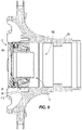
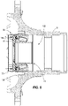
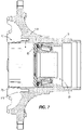
- Figs. 5-7 illustrate the use of the device 10 as an installation tool.
- the illustrated housing 18 is a wheel hub into which the bearing assembly is installed.
- the device can be used to package and install other bearing assemblies into other types of housings as well.
- the first end 76 of the sleeve 70 is aligned with an axial face 118 of the housing 18, adjacent to a bore or cavity 122 into which the bearing assembly 14 is to be installed.
- an axial force F is applied to the disc 86 in a direction toward the housing 18.
- the axial force F is preferably provided at the planar portion 106, and can be applied using a pipe, tube or other suitable device.
- the axial force F causes both the disc 86 and the bearing assembly 14 to slide within the sleeve 70 toward the housing 18, and eventually to exit the sleeve 70 and further enter or move into the cavity 122 in the housing 18.
- the axial force F is continued to be applied to the disc 86 until the bearing assembly 14 reaches its final, installed position within the cavity 122, as shown in Fig. 7 .
- the disc 86 is then removed from the cavity 122 in the housing 18, leaving the bearing assembly 14 installed in the housing 18.
- the removed disc 86, along with the sleeve 70, can be re-used, recycled, or discarded.
- Figs. 1-7 illustrates the sleeve 70 and the disc 86 as being separate components
- the disc 86a is initially integral with the sleeve 70a and can be separated from the sleeve 70a to permit the sliding of the disc 86a along the sleeve inner diameter 74a in the axial direction when it is time to install the bearing assembly 14 using the device 10a.
- Figs. 8-10 illustrates the embodiment of Figs. 1-7 illustrates the sleeve 70 and the disc 86 as being separate components
- the disc 86a is initially integral with the sleeve 70a and can be separated from the sleeve 70a to permit the sliding of the disc 86a along the sleeve inner diameter 74a in the axial direction when it is time to install the bearing assembly 14 using the device 10a.
- the disc 86a and the sleeve 70a are initially molded from plastic or other materials (similar or dissimilar) as one piece, and one or more shear features 126 (e.g., perforations, a thinned wall portion, one or more stakes, etc.) can be molded between the disc 86a and the sleeve 70a to facilitate separation of the disc 86a from the sleeve 70a upon application of a force to the disc 86a.
- shear features 126 e.g., perforations, a thinned wall portion, one or more stakes, etc.
- the initially separate disc 86 and sleeve 70 could be secured (bonded, adhered, or otherwise secured) together so that an application of axial force is needed to separate the disc 86 from the sleeve 70 to begin axial movement of the disc 86 relative to the sleeve 70. Separation could include breaking of adhesive or bonding, which could be considered shear features, or breaking or deforming of other shear or breakaway features.
- the sleeve 70a does not include a flange for limiting the movement of the disc 86a in one direction. Because the disc 86a is initially integral with the sleeve 70a (e.g. molded as a single piece with shear features/stakes 126), no flange is required to initially limit movement of the disc 86a relative to the sleeve 70a. Instead the stakes 126 initially secure the disc 86a in position relative to the sleeve 70a. As shown, there are eight stakes 126 provided (i.e., integrally molded) on the outer surface 90a of the disc 86a and/or on the inner surface of the sleeve 70a.
- the stakes 126 are positioned between the ridges Ra so as not to interfere with the axial sliding of the disc 86a after the stakes 126 are broken (shown in phantom in Fig. 10 ) to permit movement of the disc 86a within the sleeve 70a.
- the disc 86a is staked to the sleeve 70a at an axial location spaced from both the first and second ends 76a, 78a of the sleeve 70a.
- the initial spacing of the disc 86a away from the second end 78a enables a user to select a pressing tool (e.g., a pipe or tube) with the appropriate outside diameter by making sure that the pressing tool will fit into the opening in the second end 78a and within the inner diameter 74a.
- a pressing tool e.g., a pipe or tube
Landscapes
- Engineering & Computer Science (AREA)
- General Engineering & Computer Science (AREA)
- Mechanical Engineering (AREA)
- Mounting Of Bearings Or Others (AREA)
- Road Signs Or Road Markings (AREA)
Description
- This application claims the benefit of
U.S. Provisional Patent Application No. 62/165,291 filed May 22, 2015 - The present invention relates to bearings, and more specifically to a device and method for packaging and installing a bearing.
- Transporting and installing bearings is sometimes complicated with bearings that are not unitized or held together by their own components. Specifically, some bearings include an inner ring, an outer ring, and a plurality of rolling elements between the inner and outer rings. Where the bearing assembly is not otherwise unitized, or held together, the outer ring can move relative to the inner ring and roller assembly, resulting in potential seal and/or inner ring and/or cage damage.
-
DE 102010038990 discloses a shaft bearing device in which a bearing is retained in a sleeve-like portion of an attachment unit by means of a disc-like support unit which connects to the attachment unit with a bayonet fixing to retain the bearing therebetween. - The present invention provides a device for packaging (i.e., retaining and transporting) and installing a bearing assembly that may not be unitized.
- The invention provides a device for supporting and installing a bearing assembly. The bearing assembly includes an inner ring having an inner ring axial face, an outer ring having an outer ring axial face and an outer diameter, and a plurality of rolling elements positioned between the inner ring and the outer ring. The device comprises a sleeve having a first end with an opening through which the bearing assembly can be received into or removed from the sleeve, a second end opposite the first end, and an inner diameter sized and configured to receive and support the outer ring along the outer diameter, and a disc positioned within the sleeve. The disc includes a disc outer diameter sized and configured to permit sliding of the disc along the sleeve inner diameter in an axial direction of the sleeve, and a disc face surface facing the first end and sized and configured to engage the inner ring axial face, or the outer ring axial face, or both when the bearing assembly is received in the sleeve.
- In the invention, the sleeve includes a plurality of spaced-apart ridges extending axially along the sleeve, the ridges collectively defining the inner diameter of the sleeve such that the inner diameter of the sleeve is configured for intermittent contact with the outer diameter of the outer ring. The disc and the sleeve can initially be molded from plastic as one piece, and a shear feature is molded between the disc and the sleeve to facilitate separation of the disc from the sleeve upon application of a force to the disc.
- The invention also provides a method of installing a bearing assembly into a housing using a device for supporting and installing the bearing assembly. The device has a sleeve with an inner diameter sized and configured to receive and support the bearing assembly, and a disc positioned within the sleeve. The disc includes a disc outer diameter sized and configured to permit sliding of the disc along the sleeve inner diameter in an axial direction of the sleeve, and a disc face surface sized and configured to engage the bearing assembly when the bearing assembly is received in the sleeve, wherein the inner diameter of the sleeve includes a plurality of spaced-apart ridges extending axially along the sleeve, the ridges collectively defining the inner diameter of the sleeve. The method includes aligning the sleeve of the device with the housing into which the bearing assembly is to be installed, applying an axial force to the disc in a direction toward the housing, the axial force causing the disc and the bearing assembly to slide within the sleeve toward the housing, and to exit the sleeve and enter the housing, and removing the disc from within the housing, leaving the bearing assembly installed in the housing.
- Other aspects of the invention will become apparent by consideration of the detailed description and accompanying drawings.
-
-
Fig. 1 is a rear perspective view of a device for supporting and installing a bearing assembly. -
Fig. 2 is an exploded view of the device ofFig. 1 . -
Fig. 3 illustrates the device ofFig. 1 , shown with a bearing assembly supported therein. -
Fig. 4 is a section view taken along line 4-4 ofFig. 3 . -
Figs. 5-7 illustrate a method of installing a bearing assembly initially retained within the device ofFig. 1 into a housing. -
Fig. 8 is a rear perspective view of another embodiment of a device for supporting and installing a bearing assembly. -
Fig. 9 is a front perspective view of the device ofFig. 8 . -
Fig. 10 is a partial section view of the device ofFig.8 illustrating the operation of a shear feature. - Before any embodiments of the invention are explained in detail, it is to be understood that the invention is not limited in its application to the details of construction and the arrangement of components set forth in the following description or illustrated in the following drawings. The invention is capable of other embodiments and of being practiced or of being carried out in various ways.
-
Figs. 1-7 illustrate adevice 10 for supporting and installing abearing assembly 14. The device can be used to package and transport thebearing assembly 14, and can further be used to install thebearing assembly 14 into a housing 18 (e.g., a wheel hub - seeFigs. 5-7 ). - As seen in
Figs. 3-7 , the illustratedbearing assembly 14 is a non-unitized rolling element bearing as is known to those skilled in the art. Thebearing assembly 14 includes aninner ring 22 having an inner ring, axially-facingaxial face 26 and araceway 30. Thebearing assembly 14 further includes anouter ring 34 having an outer ring, axially-facingaxial face 38, which in the illustrated embodiment, is defined on anextension 42 of theouter ring 34. Theouter ring 34 further includes anouter surface 46 defining an outer diameter of theouter ring 34, and araceway 50. A plurality of rolling elements 54 (e.g., rollers) are positioned between the inner andouter rings respective raceways cage 58 is provided to maintain the relative spacing between therolling elements 54. A seal orseal assembly 62 is also positioned between theextension 42 of theouter ring 34 and arib 66 of theinner ring 22. The illustratedbearing assembly 14 is non-unitized, meaning that thebearing assembly 14 is not held together and theouter ring 34 can move relative to theinner ring 22 and roller assembly, resulting in potential seal and/or inner ring and/or cage damage. - The
device 10 includes asleeve 70 having aninner diameter 74 sized and configured to receive and support theouter ring 34 along the outer diameter of theouter surface 46. The illustratedsleeve 70 is generally cylindrical (shown with a slight taper along its outer surface) and tubular to conform in shape to the cylindricalouter surface 46 of theouter ring 34. Thesleeve 70 includes a plurality of spaced-apart ridges R (seeFig. 2 ) that extend axially along at least a portion of thesleeve 70 and that collectively define theinner diameter 74 of thesleeve 70 such that radially inner-most surfaces of the ridges R engage and support theouter ring 34 along itsouter surface 46. While eight evenly-spaced ridges R are illustrated, in other embodiments, the number and spacing of the ridges R can vary. Additionally, the geometry of the ridges R may take other forms, such as semicircular or other cross-sectional geometries. The ridges R also operate to relieve stress (e.g., hoop stress) in thesleeve 70 when thebearing assembly 14 is received therein. The inner-most surfaces of the ridges R are dimensioned to provide a tight fit around theouter ring 34 when theouter ring 34 is positioned within thesleeve 70 while also ensuring that contact with theouter surface 46 of theouter ring 34 is circumferentially intermittent instead of continuous around the entire circumference. In addition to relieving stress in thesleeve 70 as mentioned above, this can also facilitate the ability of thebearing assembly 14 to slide within thesleeve 70. - The axial length of the
sleeve 70 can be shorter than the axial length of theouter ring 34, as shown, or if desired, can be the same as or longer than the axial length of theouter ring 34. The sleeve has afirst end 76 open to receive thebearing assembly 14 therein. The sleeve further includes asecond end 78 having ashoulder 82 that extends radially inwardly from theinner diameter 74 such that an opening defined at thesecond end 78 is smaller than the opening defined at thefirst end 76. Thesleeve 70 can be made of molded plastic or other suitable materials. The wall thickness of thesleeve 70 can vary as desired according to packaging requirements. - The device further includes a
disc 86 positioned within thesleeve 70. The disc can also be made of molded plastic or other suitable materials, and in the illustrated embodiment is a separate piece from thesleeve 70. Thedisc 86 has a radiallyouter surface 90 defining a disc outer diameter sized and configured to permit sliding of thedisc 86 along the sleeveinner diameter 74 in an axial direction of thesleeve 70. A tight fit can be used as long as relative sliding can take place. In the illustrated embodiment, theouter surface 90 has a diameter slightly smaller than theinner diameter 74 as defined by the ridges R. In other embodiments, theouter surface 90 could include cut-outs or notches corresponding in shape to the cross-section of the ridges R such that thedisc 86 would slide within thesleeve 70 as guided and anti-rotated by the interaction between the ridges R and the corresponding cut-outs. - The illustrated
disc 86 further defines adisc face surface 94 sized and configured to engage at least one of the inner ringaxial face 26 and the outer ringaxial face 38 when thebearing assembly 14 is received and supported in thesleeve 70. Thedisc face surface 94 includesrecesses 98 where material (e.g., plastic) has been removed to reduce the amount of material needed for thedisc 86, while still providing areas of thickened material for strength and rigidity. Thedisc 86 further includes adisc pressing surface 102 opposite thedisc face surface 94. Thedisc pressing surface 102 has aplanar portion 106 configured to receive a pressing tool (e.g., a tubular member such as a pipe or other metal tubing), and anon-planar portion 110 radially inward of theplanar portion 106. Theplanar portion 106 is at or adjacent the outer-most radius of thedisc 86 to encourage application of the pressing force F (discussed further below) at this location. Text orother indicia 114 can be provided on theplanar portion 106 as explicit instructions to the user to apply the pressing force at theplanar portion 106. The illustratednon-planar portion 110 tapers toward thedisc face surface 94 to create a concavity radially inward of theplanar portion 106. This concavity discourages and/or prevents application of the pressing force in this location. However, in other embodiments, the entiredisc pressing surface 102 could be planar. - The illustrated
disc 86 is annular in shape. In other embodiments, thedisc 86 need not be annular. Furthermore, thedisc 86 could engage both the inner ringaxial face 26 and the outer ringaxial face 38, instead of only the outer ringaxial face 38 as shown. As shown inFigs. 1 and4 , thedisc 86 abuts theshoulder 82 adjacent thesecond end 78 of thesleeve 70 so that theshoulder 82 limits axial movement of thedisc 86 in a direction toward thesecond end 78, but allows axial movement of thedisc 86 within thesleeve 70 toward thefirst end 76. - As shown in
Figs. 3 and4 , the bearingassembly 14 can be received and supported within thedevice 10 for storage, transportation, and handling. When the bearingassembly 14 is housed in thedevice 10, thesleeve 70 snugly envelopes theouter ring 34, and thedisc 86 engages or abuts the outer ringaxial face 38, and perhaps even theseal 62. As mentioned above, in other embodiments, thedisc 86 may also engage the inner ringaxial face 26. Together, thesleeve 70 and thedisc 86 cooperate to unitize the bearingassembly 14 and prevent damage caused by relative movement of the bearing assembly components. - The
device 10 can also operate as an installation tool for installing the bearingassembly 14 into ahousing 18 from within thedevice 10.Figs. 5-7 illustrate the use of thedevice 10 as an installation tool. The illustratedhousing 18 is a wheel hub into which the bearing assembly is installed. Of course, the device can be used to package and install other bearing assemblies into other types of housings as well. As seen inFig. 5 , thefirst end 76 of thesleeve 70 is aligned with anaxial face 118 of thehousing 18, adjacent to a bore orcavity 122 into which the bearingassembly 14 is to be installed. Because the illustratedsleeve 70 has a shorter axial length than the outer ring 34 (and the entire bearing assembly 14), the placement of thefirst end 76 of thesleeve 70 against theaxial face 118 pilots the bearingassembly 14 partially into thecavity 122. Next, as shown inFig. 6 , an axial force F is applied to thedisc 86 in a direction toward thehousing 18. As discussed above, the axial force F is preferably provided at theplanar portion 106, and can be applied using a pipe, tube or other suitable device. Due to the engagement between thedisc face surface 94 and the outer ringaxial face 38, the axial force F causes both thedisc 86 and the bearingassembly 14 to slide within thesleeve 70 toward thehousing 18, and eventually to exit thesleeve 70 and further enter or move into thecavity 122 in thehousing 18. The axial force F is continued to be applied to thedisc 86 until the bearingassembly 14 reaches its final, installed position within thecavity 122, as shown inFig. 7 . Thedisc 86 is then removed from thecavity 122 in thehousing 18, leaving the bearingassembly 14 installed in thehousing 18. The removeddisc 86, along with thesleeve 70, can be re-used, recycled, or discarded. - While the embodiment of
Figs. 1-7 illustrates thesleeve 70 and thedisc 86 as being separate components, in an alternative embodiment of thedevice 10a shown inFigs. 8-10 , thedisc 86a is initially integral with thesleeve 70a and can be separated from thesleeve 70a to permit the sliding of thedisc 86a along the sleeveinner diameter 74a in the axial direction when it is time to install the bearingassembly 14 using thedevice 10a. As illustrated inFigs. 8-10 , thedisc 86a and thesleeve 70a are initially molded from plastic or other materials (similar or dissimilar) as one piece, and one or more shear features 126 (e.g., perforations, a thinned wall portion, one or more stakes, etc.) can be molded between thedisc 86a and thesleeve 70a to facilitate separation of thedisc 86a from thesleeve 70a upon application of a force to thedisc 86a. In yet another embodiment, the initiallyseparate disc 86 andsleeve 70 could be secured (bonded, adhered, or otherwise secured) together so that an application of axial force is needed to separate thedisc 86 from thesleeve 70 to begin axial movement of thedisc 86 relative to thesleeve 70. Separation could include breaking of adhesive or bonding, which could be considered shear features, or breaking or deforming of other shear or breakaway features. - Referring to the
device 10a shown inFigs. 8-10 , like parts have been given like reference numbers to thedevice 10 with the addition of the suffix "a." The similarities in the like parts and features will not be discussed again, as they were discussed above with respect to thedevice 10. Only differences between thedevices - For example, the
sleeve 70a does not include a flange for limiting the movement of thedisc 86a in one direction. Because thedisc 86a is initially integral with thesleeve 70a (e.g. molded as a single piece with shear features/stakes 126), no flange is required to initially limit movement of thedisc 86a relative to thesleeve 70a. Instead thestakes 126 initially secure thedisc 86a in position relative to thesleeve 70a. As shown, there are eightstakes 126 provided (i.e., integrally molded) on theouter surface 90a of thedisc 86a and/or on the inner surface of thesleeve 70a. Thestakes 126 are positioned between the ridges Ra so as not to interfere with the axial sliding of thedisc 86a after thestakes 126 are broken (shown in phantom inFig. 10 ) to permit movement of thedisc 86a within thesleeve 70a. As best seen inFig. 8 , thedisc 86a is staked to thesleeve 70a at an axial location spaced from both the first andsecond ends sleeve 70a. The initial spacing of thedisc 86a away from thesecond end 78a enables a user to select a pressing tool (e.g., a pipe or tube) with the appropriate outside diameter by making sure that the pressing tool will fit into the opening in thesecond end 78a and within theinner diameter 74a. - In this alternative embodiment of the
device 10a, in which thesleeve 70a and thedisc 86a are initially formed as one piece and therefore connected together, or in other alternatives in which the disc and sleeve are separately formed as two pieces but are initially secured together, applying the axial force F to thedisc 86a as shown inFig. 10 breaks the shear feature 126 (e.g., perforations, a thinned wall portion, one or more stakes, adhesive, etc.) initially connecting thedisc 86a and thesleeve 70a to permit thedisc 86a to move in the piston-like manner relative to thesleeve 70a. The remainder of the bearing assembly installation method described above remains the same. - Various features and advantages of the invention are set forth in the following claims.
Claims (13)
- A device (10) for supporting and installing a bearing assembly (14), the bearing assembly(14) including an inner ring (22) having an inner ring axial face (26), an outer ring (34) having an outer ring axial face (38) and an outer diameter, and a plurality of rolling elements (54) positioned between the inner ring (22) and the outer ring (34), the device (10) comprising:a sleeve (70) having a first end (76) with an opening through which the bearing assembly (14) can be received into or removed from the sleeve (70), a second end (78) opposite the first end (76), and an inner diameter (74) sized and configured to receive and support the outer ring (34) along the outer diameter; anda disc (86) positioned within the sleeve (70), the disc (86) including,a disc outer diameter (90) sized and configured to permit sliding of the disc (86) along the sleeve inner diameter (74) in an axial direction of the sleeve (70), anda disc face surface (94) facing the first end (76) and sized and configured to engage the inner ring axial face (26), or the outer ring axial face (38), or both when the bearing assembly (14) is received in the sleeve (70)wherein the inner diameter of the sleeve (70) includes a plurality of spaced-apart ridges (R) extending axially along the sleeve (70), the ridges (R) collectively defining the inner diameter (74) of the sleeve (70) such that the inner diameter of the sleeve (70) is configured for intermittent contact with the outer diameter of the outer ring (34).
- The device of claim 1, wherein the disc (86) is annular in shape.
- The device of claim 1 or 2, wherein the disc (86) is initially a separate component from the sleeve (70).
- The device of claim 3, wherein the sleeve (70) includes a shoulder (82) extending radially inwardly from the inner diameter, the shoulder (82) operable to limit axial movement of the disc (86) in one direction.
- The device of claim 1 or 2, wherein the disc (86) is secured to the sleeve (70) and can be separated from the sleeve (70) to permit the sliding of the disc (86) along the sleeve inner diameter in the axial direction.
- The device of claim 1 or 2, wherein the disc (86) is initially integral with the sleeve (70) and can be separated from the sleeve (70) to permit the sliding of the disc (86) along the sleeve inner diameter in the axial direction.
- The device of claim 6, wherein the disc (86) and the sleeve (70) are initially molded from plastic as one piece, and wherein a shear feature (126) is molded between the disc (86) and the sleeve (70) to facilitate separation of the disc (86) from the sleeve (70) upon application of a force to the disc (86).
- The device of claim 7, wherein the shear feature (126) includes a plurality of stakes positioned about the disc outer diameter.
- The device of any of the preceding claims, wherein the disc face surface (94) includes recesses (98).
- The device of any of the preceding claims, wherein the disc (86) further includes a disc pressing surface (102) opposite the disc face surface (94), the disc pressing surface (102) having a planar portion (106) configured to receive a pressing tool.
- A method of installing a bearing assembly (14) into a housing (18) using a device (10) for supporting and installing the bearing assembly (14), the device having a sleeve (70) with an inner diameter (74) sized and configured to receive and support the bearing assembly (14), and a disc (86) positioned within the sleeve (70), the disc including a disc outer diameter (90) sized and configured to permit sliding of the disc (86) along the sleeve inner diameter (74) in an axial direction of the sleeve and a disc face surface (94) sized and configured to engage the bearing assembly when the bearing assembly (14) is received in the sleeve (70), wherein the inner diameter of the sleeve (70) includes a plurality of spaced-apart ridges (R) extending axially along the sleeve (70), the ridges (R) collectively defining the inner diameter (74) of the sleeve (70); the method comprising:aligning the sleeve (70) of the device with the housing (18) into which the bearing assembly (14) is to be installed;applying an axial force to the disc (86) in a direction toward the housing (18), the axial force causing the disc (86) and the bearing assembly (14) to slide within the sleeve (70) toward the housing (18), and to exit the sleeve (70) and enter the housing (18); andremoving the disc (86) from within the housing (18), leaving the bearing assembly (14) installed in the housing (18).
- The method of claim 11, wherein applying the axial force to the disc (86) breaks a shear feature (126) initially connecting the disc (86) and the sleeve (70) to permit the disc (86) to move relative to the sleeve (70).
- The method of claim 11 or 12, wherein the disc (86) further includes a disc pressing surface (102) opposite the disc face surface (94), the disc pressing surface (102) having a planar portion (106), the method further comprising applying the axial force to the planar portion (106) of the disc pressing surface (102).
Priority Applications (1)
| Application Number | Priority Date | Filing Date | Title |
|---|---|---|---|
| PL16725709.6T PL3298293T5 (en) | 2015-05-22 | 2016-05-17 | Bearing package and installation tool |
Applications Claiming Priority (2)
| Application Number | Priority Date | Filing Date | Title |
|---|---|---|---|
| US201562165291P | 2015-05-22 | 2015-05-22 | |
| PCT/US2016/032829 WO2016191144A1 (en) | 2015-05-22 | 2016-05-17 | Bearing package and installation tool |
Publications (3)
| Publication Number | Publication Date |
|---|---|
| EP3298293A1 EP3298293A1 (en) | 2018-03-28 |
| EP3298293B1 EP3298293B1 (en) | 2019-07-24 |
| EP3298293B2 true EP3298293B2 (en) | 2022-09-07 |
Family
ID=56084415
Family Applications (1)
| Application Number | Title | Priority Date | Filing Date |
|---|---|---|---|
| EP16725709.6A Active EP3298293B2 (en) | 2015-05-22 | 2016-05-17 | Bearing package and installation tool |
Country Status (7)
| Country | Link |
|---|---|
| US (1) | US10514064B2 (en) |
| EP (1) | EP3298293B2 (en) |
| ES (1) | ES2746301T5 (en) |
| LT (1) | LT3298293T (en) |
| PL (1) | PL3298293T5 (en) |
| PT (1) | PT3298293T (en) |
| WO (1) | WO2016191144A1 (en) |
Families Citing this family (3)
| Publication number | Priority date | Publication date | Assignee | Title |
|---|---|---|---|---|
| CN108019434B (en) * | 2017-12-31 | 2023-09-12 | 无锡华洋滚动轴承有限公司 | Sealing ring pressing-in device |
| DE102019211872A1 (en) * | 2019-08-07 | 2021-02-11 | Aktiebolaget Skf | Storage and assembly aid device |
| CN111795063A (en) * | 2020-07-20 | 2020-10-20 | 佳木斯电机股份有限公司 | Integrated bearing structure mounted on bearing seat of canned motor pump |
Citations (5)
| Publication number | Priority date | Publication date | Assignee | Title |
|---|---|---|---|---|
| US3844010A (en) † | 1973-04-30 | 1974-10-29 | Frost & Son C L | Method of making a bearing housing assembly |
| WO2007115539A1 (en) † | 2006-04-12 | 2007-10-18 | Schaeffler Kg | Interchangeable wheel bearing unit, for example for commercial vehicles and method for assembling a wheel bearing unit |
| JP2008169957A (en) † | 2007-01-15 | 2008-07-24 | Jtekt Corp | Bearing device and assembling error preventing tool for bearing |
| DE102009025536A1 (en) † | 2009-06-19 | 2010-12-23 | Schaeffler Technologies Gmbh & Co. Kg | Roller bearing unit i.e. wheel bearing unit, for heavy commercial vehicle, has outer ring whose part is provided for load transfer, where another part of outer ring is provided for carrying sealing element of sealing arrangement |
| DE102010038990A1 (en) † | 2010-08-06 | 2012-02-09 | Robert Bosch Gmbh | Shaft bearing device for a hand tool |
Family Cites Families (27)
| Publication number | Priority date | Publication date | Assignee | Title |
|---|---|---|---|---|
| US306510A (en) * | 1884-10-14 | Foubth to the cuknt | ||
| US628138A (en) * | 1898-07-02 | 1899-07-04 | William J Busse | Ball-bearing for cycles. |
| US2441981A (en) * | 1943-11-01 | 1948-05-25 | Parker Pattern And Foundry Com | Bearing driver |
| US2852838A (en) * | 1954-07-03 | 1958-09-23 | Saab Scania Ab | Tool for mounting anti-friction bearings |
| US2945730A (en) | 1956-08-24 | 1960-07-19 | Tyson Bearing Corp | Seal for a separable bearing that locks the bearing partsinto a unit |
| US3084791A (en) | 1958-04-11 | 1963-04-09 | E P S Res & Dev Ltd | Method and means of packing and preserving corrodible objects or components |
| US3165949A (en) * | 1961-08-30 | 1965-01-19 | Federal Mogul Bower Bearings | Seal driver assembly |
| US3783485A (en) * | 1972-07-19 | 1974-01-08 | G Nastasi | Device for extracting and for inserting bearings in a roller skate wheel |
| US4509241A (en) * | 1984-04-09 | 1985-04-09 | Freeland John A | Combination bearing removal and installation tool |
| FR2678692B1 (en) * | 1991-07-05 | 1995-05-12 | Skf France | WATERPROOF SENSOR ASSEMBLY INTEGRATED INTO AN INFORMATION SENSOR BEARING AND BEARING EQUIPPED WITH SUCH AN ASSEMBLY. |
| US5165169A (en) * | 1991-10-31 | 1992-11-24 | The United States Of America As Represented By The Administrator Of The National Aeronautics And Space Administration | Bearing servicing tool |
| US5573311A (en) * | 1994-07-05 | 1996-11-12 | Warn Industries, Inc. | Anti-rotation device for wheel spindle nut |
| US5442854A (en) * | 1994-12-02 | 1995-08-22 | Deere & Company | Process and apparatus for assembling multiple rolling bearing and a rotating member onto a shaft |
| DE19607024C2 (en) * | 1996-02-24 | 1998-08-20 | Fag Automobiltechnik Ag | Method of attaching a rolling bearing ring |
| US6170832B1 (en) * | 1998-03-26 | 2001-01-09 | Hermann H. F. Ernst | Fluid ring seal system and method |
| US6257078B1 (en) * | 1998-06-15 | 2001-07-10 | R. Lee Vencill | Bearing adjustment and monitoring system |
| US6062737A (en) * | 1998-11-03 | 2000-05-16 | Thienes; James E. | Wheel hub retention apparatus |
| US6234293B1 (en) * | 1999-07-23 | 2001-05-22 | Luff Industries Ltd. | Conveyor-belt roller assembly |
| US6544140B2 (en) * | 2001-04-17 | 2003-04-08 | The Timken Company | Pinion mounting with direct tapered roller bearing arrangement |
| US6581288B1 (en) * | 2002-04-17 | 2003-06-24 | The Timken Company | Method of assembling a package bearing and an assembly tool therefore |
| US6796031B1 (en) * | 2003-03-14 | 2004-09-28 | The Timken Company | Process for setting bearings and verifying force preload |
| US7478464B2 (en) * | 2007-05-22 | 2009-01-20 | Hsin Fa Kang | Tool set for assembling an automobile tapered bearing |
| DE102008009283B4 (en) * | 2008-02-15 | 2021-07-29 | Schaeffler Technologies AG & Co. KG | Wheel bearing device for a motor vehicle |
| EP2400172B1 (en) | 2010-06-24 | 2012-10-31 | Schaeffler Technologies AG & Co. KG | Rolling element bearing unit with splitted outer ring and transport ring |
| DE102011051961A1 (en) * | 2011-07-20 | 2013-01-24 | Zf Lenksysteme Gmbh | Device for securing a unit |
| DE102012206659B4 (en) | 2012-04-23 | 2021-02-25 | Schaeffler Technologies AG & Co. KG | Pre-assembled, press-fit rolling bearing unit |
| DE102012224423A1 (en) * | 2012-12-27 | 2014-07-03 | Senvion Se | Component arrangement, assembly method and operating method |
-
2016
- 2016-05-17 US US15/321,832 patent/US10514064B2/en active Active
- 2016-05-17 EP EP16725709.6A patent/EP3298293B2/en active Active
- 2016-05-17 LT LTEP16725709.6T patent/LT3298293T/en unknown
- 2016-05-17 WO PCT/US2016/032829 patent/WO2016191144A1/en active Application Filing
- 2016-05-17 ES ES16725709T patent/ES2746301T5/en active Active
- 2016-05-17 PL PL16725709.6T patent/PL3298293T5/en unknown
- 2016-05-17 PT PT16725709T patent/PT3298293T/en unknown
Patent Citations (5)
| Publication number | Priority date | Publication date | Assignee | Title |
|---|---|---|---|---|
| US3844010A (en) † | 1973-04-30 | 1974-10-29 | Frost & Son C L | Method of making a bearing housing assembly |
| WO2007115539A1 (en) † | 2006-04-12 | 2007-10-18 | Schaeffler Kg | Interchangeable wheel bearing unit, for example for commercial vehicles and method for assembling a wheel bearing unit |
| JP2008169957A (en) † | 2007-01-15 | 2008-07-24 | Jtekt Corp | Bearing device and assembling error preventing tool for bearing |
| DE102009025536A1 (en) † | 2009-06-19 | 2010-12-23 | Schaeffler Technologies Gmbh & Co. Kg | Roller bearing unit i.e. wheel bearing unit, for heavy commercial vehicle, has outer ring whose part is provided for load transfer, where another part of outer ring is provided for carrying sealing element of sealing arrangement |
| DE102010038990A1 (en) † | 2010-08-06 | 2012-02-09 | Robert Bosch Gmbh | Shaft bearing device for a hand tool |
Also Published As
| Publication number | Publication date |
|---|---|
| WO2016191144A1 (en) | 2016-12-01 |
| EP3298293A1 (en) | 2018-03-28 |
| ES2746301T5 (en) | 2023-01-19 |
| EP3298293B1 (en) | 2019-07-24 |
| LT3298293T (en) | 2019-09-25 |
| PL3298293T5 (en) | 2022-12-19 |
| US20170146069A1 (en) | 2017-05-25 |
| ES2746301T3 (en) | 2020-03-05 |
| US10514064B2 (en) | 2019-12-24 |
| PL3298293T3 (en) | 2020-03-31 |
| PT3298293T (en) | 2019-09-30 |
Similar Documents
| Publication | Publication Date | Title |
|---|---|---|
| EP3298293B2 (en) | Bearing package and installation tool | |
| US10240669B2 (en) | Gearing having a first and a second housing part | |
| US20210071748A1 (en) | Gear unit having a first and a second housing part | |
| MX336140B (en) | Fluid filter system. | |
| US10514059B2 (en) | Bearing device | |
| CN107771252B (en) | Rolling bearing unit | |
| US10119573B2 (en) | Piston bearing unit, clutch, transmission and locking differential having the piston bearing unit | |
| JP2016540923A5 (en) | ||
| US10641323B2 (en) | Bearing device | |
| US9194423B2 (en) | Rolling bearing device, in particular for a steering column | |
| US8632255B2 (en) | Bearing assembly | |
| US11420468B2 (en) | Wheel hub and bearing assembly packaging | |
| JP2007205456A (en) | Tapered roller bearing | |
| EP2840265A2 (en) | Retainer cap for shaft assembly | |
| EP1759882A3 (en) | Wheel hub rolling element bearing assembly with sealing arrangement | |
| US10066663B2 (en) | Tapered roller bearing, method for producing the tapered roller bearing and method for securely mounting the tapered roller bearing | |
| GB2320305A (en) | Circlip | |
| US10711840B2 (en) | Method for manufacturing wheel bearing apparatus | |
| JP5180010B2 (en) | Tapered roller bearing | |
| CN110520643B (en) | Rolling bearing unit having snap ring and method for removing snap ring | |
| JP6557950B2 (en) | Solid needle bearing | |
| US9217473B2 (en) | Cylinder assembly using a shim | |
| EP2860414B1 (en) | Conical roller bearing | |
| US20140003758A1 (en) | Roller bearing cage with predetermined rupture point | |
| EP1901077A2 (en) | Pulsar ring and bearing device |
Legal Events
| Date | Code | Title | Description |
|---|---|---|---|
| STAA | Information on the status of an ep patent application or granted ep patent |
Free format text: STATUS: THE INTERNATIONAL PUBLICATION HAS BEEN MADE |
|
| PUAI | Public reference made under article 153(3) epc to a published international application that has entered the european phase |
Free format text: ORIGINAL CODE: 0009012 |
|
| STAA | Information on the status of an ep patent application or granted ep patent |
Free format text: STATUS: REQUEST FOR EXAMINATION WAS MADE |
|
| 17P | Request for examination filed |
Effective date: 20170421 |
|
| AK | Designated contracting states |
Kind code of ref document: A1 Designated state(s): AL AT BE BG CH CY CZ DE DK EE ES FI FR GB GR HR HU IE IS IT LI LT LU LV MC MK MT NL NO PL PT RO RS SE SI SK SM TR |
|
| AX | Request for extension of the european patent |
Extension state: BA ME |
|
| DAV | Request for validation of the european patent (deleted) | ||
| DAX | Request for extension of the european patent (deleted) | ||
| GRAP | Despatch of communication of intention to grant a patent |
Free format text: ORIGINAL CODE: EPIDOSNIGR1 |
|
| STAA | Information on the status of an ep patent application or granted ep patent |
Free format text: STATUS: GRANT OF PATENT IS INTENDED |
|
| INTG | Intention to grant announced |
Effective date: 20190301 |
|
| GRAS | Grant fee paid |
Free format text: ORIGINAL CODE: EPIDOSNIGR3 |
|
| GRAA | (expected) grant |
Free format text: ORIGINAL CODE: 0009210 |
|
| STAA | Information on the status of an ep patent application or granted ep patent |
Free format text: STATUS: THE PATENT HAS BEEN GRANTED |
|
| AK | Designated contracting states |
Kind code of ref document: B1 Designated state(s): AL AT BE BG CH CY CZ DE DK EE ES FI FR GB GR HR HU IE IS IT LI LT LU LV MC MK MT NL NO PL PT RO RS SE SI SK SM TR |
|
| REG | Reference to a national code |
Ref country code: GB Ref legal event code: FG4D |
|
| REG | Reference to a national code |
Ref country code: CH Ref legal event code: EP |
|
| REG | Reference to a national code |
Ref country code: DE Ref legal event code: R096 Ref document number: 602016017332 Country of ref document: DE |
|
| REG | Reference to a national code |
Ref country code: AT Ref legal event code: REF Ref document number: 1158534 Country of ref document: AT Kind code of ref document: T Effective date: 20190815 |
|
| REG | Reference to a national code |
Ref country code: IE Ref legal event code: FG4D |
|
| REG | Reference to a national code |
Ref country code: PT Ref legal event code: SC4A Ref document number: 3298293 Country of ref document: PT Date of ref document: 20190930 Kind code of ref document: T Free format text: AVAILABILITY OF NATIONAL TRANSLATION Effective date: 20190913 |
|
| REG | Reference to a national code |
Ref country code: SE Ref legal event code: TRGR |
|
| REG | Reference to a national code |
Ref country code: NL Ref legal event code: MP Effective date: 20190724 |
|
| REG | Reference to a national code |
Ref country code: AT Ref legal event code: MK05 Ref document number: 1158534 Country of ref document: AT Kind code of ref document: T Effective date: 20190724 |
|
| PG25 | Lapsed in a contracting state [announced via postgrant information from national office to epo] |
Ref country code: HR Free format text: LAPSE BECAUSE OF FAILURE TO SUBMIT A TRANSLATION OF THE DESCRIPTION OR TO PAY THE FEE WITHIN THE PRESCRIBED TIME-LIMIT Effective date: 20190724 Ref country code: FI Free format text: LAPSE BECAUSE OF FAILURE TO SUBMIT A TRANSLATION OF THE DESCRIPTION OR TO PAY THE FEE WITHIN THE PRESCRIBED TIME-LIMIT Effective date: 20190724 Ref country code: NO Free format text: LAPSE BECAUSE OF FAILURE TO SUBMIT A TRANSLATION OF THE DESCRIPTION OR TO PAY THE FEE WITHIN THE PRESCRIBED TIME-LIMIT Effective date: 20191024 Ref country code: AT Free format text: LAPSE BECAUSE OF FAILURE TO SUBMIT A TRANSLATION OF THE DESCRIPTION OR TO PAY THE FEE WITHIN THE PRESCRIBED TIME-LIMIT Effective date: 20190724 Ref country code: NL Free format text: LAPSE BECAUSE OF FAILURE TO SUBMIT A TRANSLATION OF THE DESCRIPTION OR TO PAY THE FEE WITHIN THE PRESCRIBED TIME-LIMIT Effective date: 20190724 Ref country code: BG Free format text: LAPSE BECAUSE OF FAILURE TO SUBMIT A TRANSLATION OF THE DESCRIPTION OR TO PAY THE FEE WITHIN THE PRESCRIBED TIME-LIMIT Effective date: 20191024 |
|
| PG25 | Lapsed in a contracting state [announced via postgrant information from national office to epo] |
Ref country code: RS Free format text: LAPSE BECAUSE OF FAILURE TO SUBMIT A TRANSLATION OF THE DESCRIPTION OR TO PAY THE FEE WITHIN THE PRESCRIBED TIME-LIMIT Effective date: 20190724 Ref country code: LV Free format text: LAPSE BECAUSE OF FAILURE TO SUBMIT A TRANSLATION OF THE DESCRIPTION OR TO PAY THE FEE WITHIN THE PRESCRIBED TIME-LIMIT Effective date: 20190724 Ref country code: AL Free format text: LAPSE BECAUSE OF FAILURE TO SUBMIT A TRANSLATION OF THE DESCRIPTION OR TO PAY THE FEE WITHIN THE PRESCRIBED TIME-LIMIT Effective date: 20190724 Ref country code: GR Free format text: LAPSE BECAUSE OF FAILURE TO SUBMIT A TRANSLATION OF THE DESCRIPTION OR TO PAY THE FEE WITHIN THE PRESCRIBED TIME-LIMIT Effective date: 20191025 Ref country code: IS Free format text: LAPSE BECAUSE OF FAILURE TO SUBMIT A TRANSLATION OF THE DESCRIPTION OR TO PAY THE FEE WITHIN THE PRESCRIBED TIME-LIMIT Effective date: 20191124 |
|
| REG | Reference to a national code |
Ref country code: ES Ref legal event code: FG2A Ref document number: 2746301 Country of ref document: ES Kind code of ref document: T3 Effective date: 20200305 |
|
| REG | Reference to a national code |
Ref country code: DE Ref legal event code: R026 Ref document number: 602016017332 Country of ref document: DE |
|
| PLBI | Opposition filed |
Free format text: ORIGINAL CODE: 0009260 |
|
| PG25 | Lapsed in a contracting state [announced via postgrant information from national office to epo] |
Ref country code: DK Free format text: LAPSE BECAUSE OF FAILURE TO SUBMIT A TRANSLATION OF THE DESCRIPTION OR TO PAY THE FEE WITHIN THE PRESCRIBED TIME-LIMIT Effective date: 20190724 Ref country code: EE Free format text: LAPSE BECAUSE OF FAILURE TO SUBMIT A TRANSLATION OF THE DESCRIPTION OR TO PAY THE FEE WITHIN THE PRESCRIBED TIME-LIMIT Effective date: 20190724 Ref country code: RO Free format text: LAPSE BECAUSE OF FAILURE TO SUBMIT A TRANSLATION OF THE DESCRIPTION OR TO PAY THE FEE WITHIN THE PRESCRIBED TIME-LIMIT Effective date: 20190724 |
|
| 26 | Opposition filed |
Opponent name: SKF GMBH Effective date: 20200416 |
|
| PG25 | Lapsed in a contracting state [announced via postgrant information from national office to epo] |
Ref country code: IS Free format text: LAPSE BECAUSE OF FAILURE TO SUBMIT A TRANSLATION OF THE DESCRIPTION OR TO PAY THE FEE WITHIN THE PRESCRIBED TIME-LIMIT Effective date: 20200224 Ref country code: SM Free format text: LAPSE BECAUSE OF FAILURE TO SUBMIT A TRANSLATION OF THE DESCRIPTION OR TO PAY THE FEE WITHIN THE PRESCRIBED TIME-LIMIT Effective date: 20190724 Ref country code: CZ Free format text: LAPSE BECAUSE OF FAILURE TO SUBMIT A TRANSLATION OF THE DESCRIPTION OR TO PAY THE FEE WITHIN THE PRESCRIBED TIME-LIMIT Effective date: 20190724 Ref country code: SK Free format text: LAPSE BECAUSE OF FAILURE TO SUBMIT A TRANSLATION OF THE DESCRIPTION OR TO PAY THE FEE WITHIN THE PRESCRIBED TIME-LIMIT Effective date: 20190724 |
|
| PLAX | Notice of opposition and request to file observation + time limit sent |
Free format text: ORIGINAL CODE: EPIDOSNOBS2 |
|
| PG2D | Information on lapse in contracting state deleted |
Ref country code: IS |
|
| PG25 | Lapsed in a contracting state [announced via postgrant information from national office to epo] |
Ref country code: SI Free format text: LAPSE BECAUSE OF FAILURE TO SUBMIT A TRANSLATION OF THE DESCRIPTION OR TO PAY THE FEE WITHIN THE PRESCRIBED TIME-LIMIT Effective date: 20190724 |
|
| PLBB | Reply of patent proprietor to notice(s) of opposition received |
Free format text: ORIGINAL CODE: EPIDOSNOBS3 |
|
| PG25 | Lapsed in a contracting state [announced via postgrant information from national office to epo] |
Ref country code: MC Free format text: LAPSE BECAUSE OF FAILURE TO SUBMIT A TRANSLATION OF THE DESCRIPTION OR TO PAY THE FEE WITHIN THE PRESCRIBED TIME-LIMIT Effective date: 20190724 Ref country code: LI Free format text: LAPSE BECAUSE OF NON-PAYMENT OF DUE FEES Effective date: 20200531 Ref country code: CH Free format text: LAPSE BECAUSE OF NON-PAYMENT OF DUE FEES Effective date: 20200531 |
|
| REG | Reference to a national code |
Ref country code: BE Ref legal event code: MM Effective date: 20200531 |
|
| PG25 | Lapsed in a contracting state [announced via postgrant information from national office to epo] |
Ref country code: LU Free format text: LAPSE BECAUSE OF NON-PAYMENT OF DUE FEES Effective date: 20200517 |
|
| PG25 | Lapsed in a contracting state [announced via postgrant information from national office to epo] |
Ref country code: IE Free format text: LAPSE BECAUSE OF NON-PAYMENT OF DUE FEES Effective date: 20200517 |
|
| PG25 | Lapsed in a contracting state [announced via postgrant information from national office to epo] |
Ref country code: BE Free format text: LAPSE BECAUSE OF NON-PAYMENT OF DUE FEES Effective date: 20200531 |
|
| PLAB | Opposition data, opponent's data or that of the opponent's representative modified |
Free format text: ORIGINAL CODE: 0009299OPPO |
|
| R26 | Opposition filed (corrected) |
Opponent name: SKF GMBH Effective date: 20200416 |
|
| REG | Reference to a national code |
Ref country code: CH Ref legal event code: PK Free format text: BERICHTIGUNGEN |
|
| RIC2 | Information provided on ipc code assigned after grant |
Ipc: F16C 19/36 20060101ALI20211203BHEP Ipc: F16C 19/54 20060101ALI20211203BHEP Ipc: F16C 41/04 20060101ALI20211203BHEP Ipc: F16C 35/067 20060101ALI20211203BHEP Ipc: F16C 35/06 20060101AFI20211203BHEP |
|
| PG25 | Lapsed in a contracting state [announced via postgrant information from national office to epo] |
Ref country code: MT Free format text: LAPSE BECAUSE OF FAILURE TO SUBMIT A TRANSLATION OF THE DESCRIPTION OR TO PAY THE FEE WITHIN THE PRESCRIBED TIME-LIMIT Effective date: 20190724 Ref country code: CY Free format text: LAPSE BECAUSE OF FAILURE TO SUBMIT A TRANSLATION OF THE DESCRIPTION OR TO PAY THE FEE WITHIN THE PRESCRIBED TIME-LIMIT Effective date: 20190724 |
|
| PG25 | Lapsed in a contracting state [announced via postgrant information from national office to epo] |
Ref country code: MK Free format text: LAPSE BECAUSE OF FAILURE TO SUBMIT A TRANSLATION OF THE DESCRIPTION OR TO PAY THE FEE WITHIN THE PRESCRIBED TIME-LIMIT Effective date: 20190724 |
|
| PUAH | Patent maintained in amended form |
Free format text: ORIGINAL CODE: 0009272 |
|
| STAA | Information on the status of an ep patent application or granted ep patent |
Free format text: STATUS: PATENT MAINTAINED AS AMENDED |
|
| 27A | Patent maintained in amended form |
Effective date: 20220907 |
|
| AK | Designated contracting states |
Kind code of ref document: B2 Designated state(s): AL AT BE BG CH CY CZ DE DK EE ES FI FR GB GR HR HU IE IS IT LI LT LU LV MC MK MT NL NO PL PT RO RS SE SI SK SM TR |
|
| REG | Reference to a national code |
Ref country code: DE Ref legal event code: R102 Ref document number: 602016017332 Country of ref document: DE |
|
| REG | Reference to a national code |
Ref country code: SE Ref legal event code: RPEO |
|
| REG | Reference to a national code |
Ref country code: ES Ref legal event code: DC2A Ref document number: 2746301 Country of ref document: ES Kind code of ref document: T5 Effective date: 20230119 |
|
| P01 | Opt-out of the competence of the unified patent court (upc) registered |
Effective date: 20230613 |
|
| REG | Reference to a national code |
Ref country code: DE Ref legal event code: R082 Ref document number: 602016017332 Country of ref document: DE Representative=s name: KRAUS & LEDERER PARTGMBB, DE |
|
| PGFP | Annual fee paid to national office [announced via postgrant information from national office to epo] |
Ref country code: GB Payment date: 20240521 Year of fee payment: 9 |
|
| PGFP | Annual fee paid to national office [announced via postgrant information from national office to epo] |
Ref country code: LT Payment date: 20240422 Year of fee payment: 9 |
|
| PGFP | Annual fee paid to national office [announced via postgrant information from national office to epo] |
Ref country code: DE Payment date: 20240521 Year of fee payment: 9 |
|
| PGFP | Annual fee paid to national office [announced via postgrant information from national office to epo] |
Ref country code: ES Payment date: 20240627 Year of fee payment: 9 |
|
| PGFP | Annual fee paid to national office [announced via postgrant information from national office to epo] |
Ref country code: FR Payment date: 20240528 Year of fee payment: 9 |
|
| PGFP | Annual fee paid to national office [announced via postgrant information from national office to epo] |
Ref country code: PL Payment date: 20240514 Year of fee payment: 9 Ref country code: PT Payment date: 20240510 Year of fee payment: 9 |
|
| PGFP | Annual fee paid to national office [announced via postgrant information from national office to epo] |
Ref country code: TR Payment date: 20240514 Year of fee payment: 9 Ref country code: SE Payment date: 20240521 Year of fee payment: 9 |
|
| PGFP | Annual fee paid to national office [announced via postgrant information from national office to epo] |
Ref country code: IT Payment date: 20240524 Year of fee payment: 9 |