EP3298285B1 - Guide vane for a bladed diffuser of a centrifugal compressor - Google Patents
Guide vane for a bladed diffuser of a centrifugal compressor Download PDFInfo
- Publication number
- EP3298285B1 EP3298285B1 EP16721363.6A EP16721363A EP3298285B1 EP 3298285 B1 EP3298285 B1 EP 3298285B1 EP 16721363 A EP16721363 A EP 16721363A EP 3298285 B1 EP3298285 B1 EP 3298285B1
- Authority
- EP
- European Patent Office
- Prior art keywords
- diffuser
- guide vane
- compressor
- vane
- guide
- Prior art date
- Legal status (The legal status is an assumption and is not a legal conclusion. Google has not performed a legal analysis and makes no representation as to the accuracy of the status listed.)
- Active
Links
Images
Classifications
-
- F—MECHANICAL ENGINEERING; LIGHTING; HEATING; WEAPONS; BLASTING
- F04—POSITIVE - DISPLACEMENT MACHINES FOR LIQUIDS; PUMPS FOR LIQUIDS OR ELASTIC FLUIDS
- F04D—NON-POSITIVE-DISPLACEMENT PUMPS
- F04D29/00—Details, component parts, or accessories
- F04D29/40—Casings; Connections of working fluid
- F04D29/42—Casings; Connections of working fluid for radial or helico-centrifugal pumps
- F04D29/44—Fluid-guiding means, e.g. diffusers
- F04D29/441—Fluid-guiding means, e.g. diffusers especially adapted for elastic fluid pumps
- F04D29/444—Bladed diffusers
-
- F—MECHANICAL ENGINEERING; LIGHTING; HEATING; WEAPONS; BLASTING
- F05—INDEXING SCHEMES RELATING TO ENGINES OR PUMPS IN VARIOUS SUBCLASSES OF CLASSES F01-F04
- F05D—INDEXING SCHEME FOR ASPECTS RELATING TO NON-POSITIVE-DISPLACEMENT MACHINES OR ENGINES, GAS-TURBINES OR JET-PROPULSION PLANTS
- F05D2220/00—Application
- F05D2220/40—Application in turbochargers
-
- F—MECHANICAL ENGINEERING; LIGHTING; HEATING; WEAPONS; BLASTING
- F05—INDEXING SCHEMES RELATING TO ENGINES OR PUMPS IN VARIOUS SUBCLASSES OF CLASSES F01-F04
- F05D—INDEXING SCHEME FOR ASPECTS RELATING TO NON-POSITIVE-DISPLACEMENT MACHINES OR ENGINES, GAS-TURBINES OR JET-PROPULSION PLANTS
- F05D2250/00—Geometry
- F05D2250/10—Two-dimensional
- F05D2250/14—Two-dimensional elliptical
-
- F—MECHANICAL ENGINEERING; LIGHTING; HEATING; WEAPONS; BLASTING
- F05—INDEXING SCHEMES RELATING TO ENGINES OR PUMPS IN VARIOUS SUBCLASSES OF CLASSES F01-F04
- F05D—INDEXING SCHEME FOR ASPECTS RELATING TO NON-POSITIVE-DISPLACEMENT MACHINES OR ENGINES, GAS-TURBINES OR JET-PROPULSION PLANTS
- F05D2250/00—Geometry
- F05D2250/50—Inlet or outlet
- F05D2250/52—Outlet
Definitions
- the invention relates to a guide vane for a diffuser of a centrifugal compressor according to the preamble of patent claim 1.
- the radial compressor usually has a receiving region in which a compressor wheel of the centrifugal compressor can be received or, in the finished state of the radial compressor, is accommodated. Furthermore, the radial compressor has a downstream of the receiving region arranged diffuser, which extends, for example, at least substantially in the radial direction. During operation of the centrifugal compressor air is compressed by means of the compressor wheel, which flows off the compressor and flows through the diffuser.
- the aforementioned guide vane can be arranged in the diffuser designed, for example, as a radial diffuser, or-in the ready-made state of the radial compressor-is arranged and serves to guide the air flowing through the diffuser.
- the guide vane on a skeleton line, wherein the guide vane may be formed, for example, as a wing profile.
- a plurality of guide vanes are arranged in the diffuser, which are arranged in the circumferential direction of the compressor wheel over its circumference successively.
- a guide is formed, which is also referred to as Nachleitgitter.
- the guide is namely arranged in the flow direction of the air downstream of the compressor wheel or the receiving area and provides advantageous flow conditions in the diffuser.
- the WO 2006/053579 A1 a turbocharger with a turbine, which comprises a turbine wheel and a guide grid arranged upstream of the turbine wheel with a plurality of guide vanes.
- Conventional guide vanes which are used in conventional centrifugal compressors and are arranged or can be arranged in the diffuser, have blade geometries, which lead to unfavorable and thus unfavorable flow conditions in the diffuser.
- a blade geometry is, for example, a geometry in the form of a profile drop, which leads to a strong constriction of a flow channel through which air can flow, so that only a small maximum mass flow of the air can flow through the flow channel.
- Another blade geometry is the so-called NACA profile, which is optimized for aircraft wings, but ensures high losses in the diffuser.
- Another blade geometry is the so-called wedge blade, which leads to high losses due to a sudden increase in channel diameter at the blade end.
- the respective guide blade is designed, for example, as a straight blade of constant thickness, this leads to an undesirably strong delay in the flow of the air, resulting in high losses.
- Another blade geometry is the so-called circular arc geometry with constant thickness. In this case, there is an insufficiently high number of free geometry parameters and this blade geometry leads to strong delays, in particular in the middle part of the guide blade.
- Object of the present invention is therefore to develop a guide vane of the type mentioned in such a way that particularly advantageous flow conditions can be realized in the diffuser.
- the entire skeleton line ie along its entire extent, is elliptical. Because of the engagement a vane having an elliptical skeleton line, an at least nearly uniform deceleration in a flow channel at least partially delimited by the vane can be realized without excessive constriction at the leading edge of the vane.
- the use of a vane with an elliptical skeleton line provides a high degree of free geometry parameters.
- the invention also includes a radial compressor, in particular for an exhaust gas turbocharger of an internal combustion engine, having a receiving area for a compressor wheel of the centrifugal compressor, with a diffuser arranged downstream of the receiving area, and with at least one guide vane according to the invention arranged in the diffuser.
- the diffuser itself is a flow channel through which air can pass, the air being compressed by means of the compressor wheel, flowing off the compressor wheel and flowing through the diffuser. Because the guide vane has an at least substantially elliptical skeleton line, particularly advantageous flow conditions can be realized in the diffuser without undue disadvantages, so that a particularly efficient operation of the radial compressor can be realized.
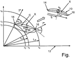
- the drawing shows in the single figure a schematic sectional view of a guide vane for a downstream of a receiving area for a compressor wheel arranged diffuser of a centrifugal compressor, with a skeleton line, which is elliptical in at least a partial region.
- the FIGURE shows a schematic sectional view of a generally designated 10 guide vane for a downstream of a receiving area for a compressor wheel arranged diffuser of a centrifugal compressor.
- the radial compressor is preferably part of an exhaust gas turbocharger, with which an example designed as a reciprocating internal combustion engine internal combustion engine of a motor vehicle Is provided.
- the internal combustion engine is designed to drive off the motor vehicle and comprises a exhaust tract of the internal combustion engine through which can flow exhaust tract and an air-flowable intake tract.
- the intake tract By means of the intake tract, the air flowing through the intake tract is guided into at least one combustion chamber, in particular cylinder, of the internal combustion engine.
- the exhaust gas turbocharger has a turbine, which is arranged in the exhaust tract and can be driven by the exhaust gas.
- the turbine comprises a turbine housing and a turbine wheel arranged in the turbine housing, which can be driven by the exhaust gas.
- the turbine wheel is rotatable about an axis of rotation relative to the turbine housing and part of a rotor of the exhaust gas turbocharger.
- the rotor further comprises the aforementioned compressor wheel and a shaft to which the turbine wheel and the compressor are rotatably connected.
- the compressor wheel can be driven by the turbine wheel via the shaft, so that - during the operation of the radial compressor - air is compressed by means of the compressor wheel.
- energy contained in the exhaust gas can be used to compress the air.
- the centrifugal compressor is arranged in the intake tract and comprises a compressor housing in which the compressor wheel is arranged.
- the compressor wheel or the rotor is rotatable about said rotation axis relative to the compressor housing.
- Said receiving region, in which the compressor wheel is arranged, is limited by the compressor housing.
- the radial compressor further comprises the aforementioned diffuser, which is arranged in the flow direction of the air through the radial compressor downstream of the receiving region and thus of the turbine wheel.
- the diffuser is a channel which can be flowed through by the air compressed by the compressor wheel and flowing away from the compressor wheel or through which flows during operation of the centrifugal compressor.
- the diffuser is designed as a radial diffuser, wherein the diffuser extends at least substantially in the radial direction.
- the centrifugal compressor further comprises a guide, which is also referred to as Nachleitgitter.
- the guide device comprises a plurality of guide vanes arranged in the diffuser and thus downstream of the receiving region or the compressor wheel, of which the guide vane designated by 10 is shown in the FIG.
- the vanes arranged in the diffuser serve to guide the air flowing through the diffuser so that advantageous flow conditions are realized in the diffuser can be.
- the previous and following versions of the guide vane 10 can be readily transferred to the other vanes of the secondary lattice.
- the vane 10 has a skeleton line X.
- the entire skeleton line X is elliptical in shape. This means that the skeleton line X is elliptical, that is, formed as part of an ellipse along its entire extension.
- the figure also shows a diagram 12, which is used as an auxiliary diagram for constructing the skeleton line X.
- the skeleton line X of the guide vane 10 is constructed as an ellipse with an elliptical thickening over the length of the chord C of the guide vane 10.
- the guide blade 10 has a blade inlet 14, via which the guide blade 10 is impinged by the air during operation of the radial compressor.
- the guide vane 10 has a vane outlet 16, via which the air flows off the vane 10.
- the blade inlet 14 and the blade outlet 16 intersect a common straight line and thus define the chord C.
- the skeleton line X is formed elliptical, the skeleton line X is also referred to below as an ellipse.
- the ellipse has exactly two intersecting angles with the chord C, wherein the intersection angle of the ellipse with the chord C of the guide vane 10 respectively, that is individually considered, less than 45 ° and together, that is, in sum, always less than 80 °.
- an entry radius of the guide vane 10 is designated, wherein f r, 4 is an exit radius of the vane 10 is designated.
- the entry radius f r, 3 is also illustrated by r 3 in the figure, wherein the exit radius f r, 4 is also illustrated by r 4 .
- a radius r 2 can be seen .
- the guide vane 10 has an entry angle ⁇ b, 3 and an exit angle ⁇ b, 4 , wherein the guide vane 10, in particular its inlet area, in which the vane 10 is flown by air, the entry angle ⁇ b, 3 encloses with the radial , Further, the guide vane 10, in particular its outlet region, over which the guide vane 10 is flowed away from the air, the exit angle ⁇ b, 4 with the radial includes, said radials in the Fig. Each with r is illustrated.
- the guide vane 10 has a maximum thickness d b and a so-called thickness reserve f b .
- the length of the chord C is also denoted by l b .
- the center M of the ellipse with respect to the chord axis of the vane 10 is not more than half the length l b of the chord C from the center S of the chord C.
- an at least substantially uniform deceleration without excessive constriction on the vane leading edge can be realized in a flow channel which is at least partially traversed by the vane 10 and can be traversed by the air Measurements of free geometry parameters can be displayed.
- a tracking grating design with an elliptical characteristic for the diffuser, which is preferably designed as a radial diffuser, as a result of which particularly advantageous flow conditions in the diffuser can be represented.
Description
Die Erfindung betrifft eine Leitschaufel für einen Diffusor eines Radialverdichters gemäß dem Oberbegriff von Patentanspruch 1.The invention relates to a guide vane for a diffuser of a centrifugal compressor according to the preamble of patent claim 1.
Derartige Leitschaufeln für Diffusoren von Radialverdichtern sind aus dem allgemeinen Stand der Technik bereits hinlänglich bekannt. Üblicherweise weist der Radialverdichter einen Aufnahmebereich auf, in welchem ein Verdichterrad des Radialverdichters aufnehmbar beziehungsweise - im fertig hergestellten Zustand des Radialverdichters - aufgenommen ist. Ferner weist der Radialverdichter einen stromab des Aufnahmebereichs angeordneten Diffusor auf, welcher sich beispielsweise zumindest im Wesentlichen in radialer Richtung erstreckt. Während des Betriebs des Radialverdichters wird mittels des Verdichterrads Luft verdichtet, welche das Verdichterrad abströmt und den Diffusor durchströmt.Such guide vanes for diffusers of centrifugal compressors are already well known from the general state of the art. The radial compressor usually has a receiving region in which a compressor wheel of the centrifugal compressor can be received or, in the finished state of the radial compressor, is accommodated. Furthermore, the radial compressor has a downstream of the receiving region arranged diffuser, which extends, for example, at least substantially in the radial direction. During operation of the centrifugal compressor air is compressed by means of the compressor wheel, which flows off the compressor and flows through the diffuser.
Die zuvor genannte Leitschaufel ist in dem beispielsweise als Radialdiffusor ausgebildeten Diffusor anordnenbar beziehungsweise - im fertig hergestellten Zustand des Radialverdichters - angeordnet und dient zum Leiten der den Diffusor durchströmenden Luft. Dabei weist die Leitschaufel eine Skelettlinie auf, wobei die Leitschaufel beispielsweise als Tragflächenprofil ausgebildet sein kann.The aforementioned guide vane can be arranged in the diffuser designed, for example, as a radial diffuser, or-in the ready-made state of the radial compressor-is arranged and serves to guide the air flowing through the diffuser. In this case, the guide vane on a skeleton line, wherein the guide vane may be formed, for example, as a wing profile.
Üblicherweise sind in dem Diffusor mehrere Leitschaufeln angeordnet, welche in Umfangsrichtung des Verdichterrads über dessen Umfang aufeinanderfolgend angeordnet sind. Durch die mehreren Leitschaufeln ist eine Leiteinrichtung gebildet, welche auch als Nachleitgitter bezeichnet wird. Die Leiteinrichtung ist nämlich in Strömungsrichtung der Luft stromab des Verdichterrads beziehungsweise des Aufnahmebereichs angeordnet und sorgt für vorteilhafte Strömungsbedingungen im Diffusor.Usually, a plurality of guide vanes are arranged in the diffuser, which are arranged in the circumferential direction of the compressor wheel over its circumference successively. Through the plurality of vanes, a guide is formed, which is also referred to as Nachleitgitter. The guide is namely arranged in the flow direction of the air downstream of the compressor wheel or the receiving area and provides advantageous flow conditions in the diffuser.
Ferner offenbart die
Herkömmliche Leitschaufeln, welche bei herkömmlichen Radialverdichtern zum Einsatz kommen und dabei im Diffusor angeordnet beziehungsweise anordenbar sind, weisen Schaufelgeometrien auf, welche zu ungünstigen und somit unvorteilhaften Strömungsbedingungen im Diffusor führen. Bei einer solchen Schaufelgeometrie handelt es sich beispielsweise um eine Geometrie in Form eines Profiltropfens, welcher zu einer starken Verengung eines von der Luft durchströmbaren Strömungskanals führt, so dass der Strömungskanal von einem nur geringen maximalen Massenstrom der Luft durchströmt werden kann. Eine weitere Schaufelgeometrie ist das so genannte NACA-Profil, welches für Flugzeugtragflächen optimiert ist, jedoch für hohe Verluste im Diffusor sorgt. Eine weitere Schaufelgeometrie ist die so genannte Keilschaufel, welche zu hohen Verluste durch eine schlagartige Kanalvergrößerung am Schaufelende führt. Ist die jeweilige Leitschaufel beispielsweise als gerade Schaufel mit konstanter Dicke ausgebildet, so führt dies zu einer unerwünscht starken Verzögerung der Strömung der Luft, woraus hohe Verluste resultieren. Eine weitere Schaufelgeometrie ist die so genannte Circular-Arc-Geometrie mit konstanter Dicke. Hierbei existiert eine nur unzureichend hohe Anzahl an freien Geometrieparametern und diese Schaufelgeometrie führt zu starken Verzögerungen insbesondere im Mittelteil der Leitschaufel.Conventional guide vanes, which are used in conventional centrifugal compressors and are arranged or can be arranged in the diffuser, have blade geometries, which lead to unfavorable and thus unfavorable flow conditions in the diffuser. Such a blade geometry is, for example, a geometry in the form of a profile drop, which leads to a strong constriction of a flow channel through which air can flow, so that only a small maximum mass flow of the air can flow through the flow channel. Another blade geometry is the so-called NACA profile, which is optimized for aircraft wings, but ensures high losses in the diffuser. Another blade geometry is the so-called wedge blade, which leads to high losses due to a sudden increase in channel diameter at the blade end. If the respective guide blade is designed, for example, as a straight blade of constant thickness, this leads to an undesirably strong delay in the flow of the air, resulting in high losses. Another blade geometry is the so-called circular arc geometry with constant thickness. In this case, there is an insufficiently high number of free geometry parameters and this blade geometry leads to strong delays, in particular in the middle part of the guide blade.
Aufgabe der vorliegenden Erfindung ist es daher, eine Leitschaufel der eingangs genannten Art derart weiter zu entwickeln, dass besonders vorteilhafte Strömungsbedingungen im Diffusor realisiert werden können.Object of the present invention is therefore to develop a guide vane of the type mentioned in such a way that particularly advantageous flow conditions can be realized in the diffuser.
Diese Aufgabe wird durch eine Leitschaufel mit den Merkmalen des Patentanspruchs 1 gelöst. Vorteilhafte Ausgestaltungen mit zweckmäßigen Weiterbildungen der Erfindung sind in den übrigen Ansprüchen angegeben.This object is achieved by a guide blade having the features of patent claim 1. Advantageous embodiments with expedient developments of the invention are specified in the remaining claims.
Um eine Leitschaufel der im Oberbegriff des Patentanspruchs 1 angegebenen Art derart weiter zu entwickeln, dass besonders vorteilhafte Strömungsbedingungen im Diffusor realisiert werden können, ist es erfindungsgemäß vorgesehen, dass die gesamte Skelettlinie, das heißt entlang ihrer gesamten Erstreckung ellipsenförmig ausgebildet ist. Durch den Einsatz einer Leitschaufel mit einer ellipsenförmigen Skelettlinie kann eine zumindest nahezu gleichmäßige Verzögerung in einem durch die Leitschaufel zumindest teilweise begrenzten Strömungskanal realisiert werden ohne dass es zu einer übermäßigen Einschnürung an der Vorderkante der Schaufel kommt. Darüber hinaus besteht durch den Einsatz einer Leitschaufel mit einer ellipsenförmigen Skelettlinie ein hohes Maß an freien Geometrieparametern.In order to further develop a guide vane of the type specified in the preamble of patent claim 1 in such a way that particularly advantageous flow conditions can be realized in the diffuser, it is provided according to the invention that the entire skeleton line, ie along its entire extent, is elliptical. Because of the engagement a vane having an elliptical skeleton line, an at least nearly uniform deceleration in a flow channel at least partially delimited by the vane can be realized without excessive constriction at the leading edge of the vane. In addition, the use of a vane with an elliptical skeleton line provides a high degree of free geometry parameters.
Zur Erfindung gehört auch ein Radialverdichter, insbesondere für einen Abgasturbolader einer Verbrennungskraftmaschine, mit einem Aufnahmebereich für ein Verdichterrad des Radialverdichters, mit einem stromab des Aufnahmebereichs angeordneten Diffusor, und mit wenigstens einer in dem Diffusor angeordneten, erfindungsgemäßen Leitschaufel. Der Diffusor an sich ist ein von Luft durchströmbarer Strömungskanal, wobei die Luft mittels des Verdichterrads verdichtet wird, vom Verdichterrad abströmt und den Diffusor durchströmt. Dadurch, dass die Leitschaufel eine zumindest im Wesentlichen ellipsenförmige Skelettlinie aufweist, können im Diffusor besonders vorteilhafte Strömungsbedingungen ohne übermäßige Nachteile realisiert werden, so dass sich ein besonders effizienter Betrieb des Radialverdichters realisieren lässt.The invention also includes a radial compressor, in particular for an exhaust gas turbocharger of an internal combustion engine, having a receiving area for a compressor wheel of the centrifugal compressor, with a diffuser arranged downstream of the receiving area, and with at least one guide vane according to the invention arranged in the diffuser. The diffuser itself is a flow channel through which air can pass, the air being compressed by means of the compressor wheel, flowing off the compressor wheel and flowing through the diffuser. Because the guide vane has an at least substantially elliptical skeleton line, particularly advantageous flow conditions can be realized in the diffuser without undue disadvantages, so that a particularly efficient operation of the radial compressor can be realized.
Weitere Vorteile, Merkmale und Einzelheiten der Erfindung ergeben sich aus der nachfolgenden Beschreibung eines bevorzugten Ausführungsbeispiels sowie anhand der Zeichnung. Die vorstehend in der Beschreibung genannten Merkmale und Merkmalskombinationen sowie die nachfolgend in der Figurenbeschreibung genannten und/oder in der einzigen Figur alleine gezeigten Merkmale und Merkmalskombinationen sind nicht nur in der jeweils angegebenen Kombination, sondern auch in anderen Kombinationen oder in Alleinstellung verwendbar, ohne den Rahmen der Erfindung zu verlassen.Further advantages, features and details of the invention will become apparent from the following description of a preferred embodiment and from the drawing. The features and feature combinations mentioned above in the description as well as the features and feature combinations mentioned below in the figure description and / or alone in the single figure can be used not only in the respectively indicated combination but also in other combinations or alone, without the frame to leave the invention.
Die Zeichnung zeigt in der einzigen Figur eine schematische Schnittansicht einer Leitschaufel für einen stromab eines Aufnahmebereichs für ein Verdichterrad angeordneten Diffusor eines Radialverdichters, mit einer Skelettlinie, welche zumindest in einem Teilbereich ellipsenförmig ausgebildet ist.The drawing shows in the single figure a schematic sectional view of a guide vane for a downstream of a receiving area for a compressor wheel arranged diffuser of a centrifugal compressor, with a skeleton line, which is elliptical in at least a partial region.
Die Fig. zeigt in einer schematischen Schnittansicht eine im Ganzen mit 10 bezeichnete Leitschaufel für einen stromab eines Aufnahmebereichs für ein Verdichterrad angeordneten Diffusor eines Radialverdichters. Der Radialverdichter ist vorzugsweise Bestandteil eines Abgasturboladers, mit welchem eine beispielsweise als Hubkolben-Verbrennungskraftmaschine ausgebildete Verbrennungskraftmaschine eines Kraftwagens ausgestattet ist. Dabei ist die Verbrennungskraftmaschine zum Abtreiben des Kraftwagens ausgebildet und umfasst einen von Abgas der Verbrennungskraftmaschine durchströmbaren Abgastrakt sowie einen von Luft durchströmbaren Ansaugtrakt. Mittels des Ansaugtrakts wird die den Ansaugtrakt durchströmenden Luft in wenigstens einen Brennraum, insbesondere Zylinder, der Verbrennungskraftmaschine geführt.The FIGURE shows a schematic sectional view of a generally designated 10 guide vane for a downstream of a receiving area for a compressor wheel arranged diffuser of a centrifugal compressor. The radial compressor is preferably part of an exhaust gas turbocharger, with which an example designed as a reciprocating internal combustion engine internal combustion engine of a motor vehicle Is provided. In this case, the internal combustion engine is designed to drive off the motor vehicle and comprises a exhaust tract of the internal combustion engine through which can flow exhaust tract and an air-flowable intake tract. By means of the intake tract, the air flowing through the intake tract is guided into at least one combustion chamber, in particular cylinder, of the internal combustion engine.
Der Abgasturbolader weist eine Turbine auf, die in dem Abgastrakt angeordnet und von dem Abgas antreibbar ist. Hierzu umfasst die Turbine ein Turbinengehäuse sowie ein in dem Turbinengehäuse angeordnetes Turbinenrad, welches von dem Abgas antreibbar ist. Das Turbinenrad ist um eine Drehachse relativ zu dem Turbinengehäuse drehbar und Bestandteil eines Rotors des Abgasturboladers. Der Rotor umfasst ferner das zuvor genannte Verdichterrad sowie eine Welle, mit welcher das Turbinenrad und das Verdichterrad drehfest verbunden sind. Dadurch ist das Verdichterrad über die Welle von dem Turbinenrad antreibbar, so dass - während des Betriebs des Radialverdichters - Luft mittels des Verdichterrads verdichtet wird. Dadurch kann im Abgas enthaltene Energie zum Verdichten der Luft genutzt werden.The exhaust gas turbocharger has a turbine, which is arranged in the exhaust tract and can be driven by the exhaust gas. For this purpose, the turbine comprises a turbine housing and a turbine wheel arranged in the turbine housing, which can be driven by the exhaust gas. The turbine wheel is rotatable about an axis of rotation relative to the turbine housing and part of a rotor of the exhaust gas turbocharger. The rotor further comprises the aforementioned compressor wheel and a shaft to which the turbine wheel and the compressor are rotatably connected. As a result, the compressor wheel can be driven by the turbine wheel via the shaft, so that - during the operation of the radial compressor - air is compressed by means of the compressor wheel. As a result, energy contained in the exhaust gas can be used to compress the air.
Der Radialverdichter ist in dem Ansaugtrakt angeordnet und umfasst ein Verdichtergehäuse, in welchem das Verdichterrad angeordnet ist. Dabei ist das Verdichterrad beziehungsweise der Rotor um die genannte Drehachse relativ zu dem Verdichtergehäuse drehbar. Der genannte Aufnahmebereich, in welchem das Verdichterrad angeordnet ist, ist durch das Verdichtergehäuse begrenzt.The centrifugal compressor is arranged in the intake tract and comprises a compressor housing in which the compressor wheel is arranged. In this case, the compressor wheel or the rotor is rotatable about said rotation axis relative to the compressor housing. Said receiving region, in which the compressor wheel is arranged, is limited by the compressor housing.
Der Radialverdichter weist ferner den zuvor genannten Diffusor auf, welcher in Strömungsrichtung der Luft durch den Radialverdichter stromab des Aufnahmebereichs und somit des Turbinenrads angeordnet ist. Der Diffusor ist ein Kanal, welcher von der mittels des Verdichterrads verdichteten und vom Verdichterrad abströmenden Luft durchströmbar ist beziehungsweise während des Betriebs des Radialverdichters durchströmt wird. Vorzugsweise ist der Diffusor als Radialdiffusor ausgebildet, wobei sich der Diffusor zumindest im Wesentlichen in radialer Richtung erstreckt.The radial compressor further comprises the aforementioned diffuser, which is arranged in the flow direction of the air through the radial compressor downstream of the receiving region and thus of the turbine wheel. The diffuser is a channel which can be flowed through by the air compressed by the compressor wheel and flowing away from the compressor wheel or through which flows during operation of the centrifugal compressor. Preferably, the diffuser is designed as a radial diffuser, wherein the diffuser extends at least substantially in the radial direction.
Der Radialverdichter umfasst ferner eine Leiteinrichtung, welche auch als Nachleitgitter bezeichnet wird. Die Leiteinrichtung umfasst eine Mehrzahl von in dem Diffusor und somit stromab des Aufnahmebereichs beziehungsweise des Verdichterrads angeordneten Leitschaufeln, von denen in der Fig. die mit 10 bezeichnete Leitschaufel gezeigt ist. Die in dem Diffusor angeordneten Leitschaufeln dienen zum Leiten der den Diffusor durchströmenden Luft, so dass vorteilhafte Strömungsbedingungen im Diffusor realisiert werden können. Die vorigen und folgenden Ausführungen zur Leitschaufel 10 können ohne weiteres auf die anderen Leitschaufeln des Nachleitgitters übertragen werden.The centrifugal compressor further comprises a guide, which is also referred to as Nachleitgitter. The guide device comprises a plurality of guide vanes arranged in the diffuser and thus downstream of the receiving region or the compressor wheel, of which the guide vane designated by 10 is shown in the FIG. The vanes arranged in the diffuser serve to guide the air flowing through the diffuser so that advantageous flow conditions are realized in the diffuser can be. The previous and following versions of the
Aus der Fig. ist erkennbar, dass die Leitschaufel 10 eine Skelettlinie X aufweist. Um nun besonders vorteilhafte Strömungsbedingungen in dem Diffusor realisieren zu können, ist die gesamte Skelettlinie X ellipsenförmig ausgebildet ist. Dies bedeutet, dass die Skelettlinie X entlang ihrer gesamten Erstreckung ellipsenförmig, das heißt als Teil einer Ellipse ausgebildet ist.From the Fig. It can be seen that the
Die Fig. zeigt auch ein Diagramm 12, welches als Hilfsdiagramm zum Konstruieren der Skelettlinie X verwendet wird. Aus der Fig. ist besonders gut erkennbar, dass die Skelettlinie X der Leitschaufel 10 als Ellipse mit elliptischer Aufdickung über die Länge der Sehne C der Leitschaufel 10 konstruiert wird. Die Leitschaufel 10 weist dabei einen Schaufeleintritt 14 auf, über welchen die Leitschaufel 10 während des Betriebs des Radialverdichters von der Luft angeströmt wird. Ferner weist die Leitschaufel 10 einen Schaufelaustritt 16 auf, über welchen die Luft die Leitschaufel 10 abströmt. Der Schaufeleintritt 14 und der Schaufelaustritt 16 schneiden eine gemeinsame Gerade und definieren so die Sehne C.The figure also shows a diagram 12, which is used as an auxiliary diagram for constructing the skeleton line X. It can be seen particularly clearly from the figure that the skeleton line X of the
Da die Skelettlinie X ellipsenförmig ausgebildet ist, wird die Skelettlinie X im Folgenden auch als Ellipse bezeichnet. Die Ellipse weist genau zwei Schnittwinkel mit der Sehne C auf, wobei die Schnittwinkel der Ellipse mit der Sehne C der Leitschaufel 10 jeweils, das heißt einzeln betrachtet, geringer als 45° und gemeinsam, das heißt in Summe, stets geringer als 80° sind.Since the skeleton line X is formed elliptical, the skeleton line X is also referred to below as an ellipse. The ellipse has exactly two intersecting angles with the chord C, wherein the intersection angle of the ellipse with the chord C of the
Mit fr,3 ist ein Eintrittsradius der Leitschaufel 10 bezeichnet, wobei mit fr,4 ein Austrittsradius der Leitschaufel 10 bezeichnet ist. Der Eintrittsradius fr,3 ist in der Fig. auch durch r3 veranschaulicht, wobei der Austrittsradius fr,4 auch durch r4 veranschaulicht ist. Ferner ist in der Fig. ein Radius r2 erkennbar. Darüber hinaus weist die Leitschaufel 10 einen Eintrittswinkel αb,3 und einen Austrittswinkel αb,4 auf, wobei die Leitschaufel 10, insbesondere ihr Eintrittsbereich, in welchem die Leitschaufel 10 von Luft angeströmt wird, den Eintrittswinkel αb,3 mit der Radialen einschließt. Ferner schließt die Leitschaufel 10, insbesondere ihr Austrittsbereich, über welchem die Leitschaufel 10 von der Luft abgeströmt wird, den Austrittswinkel αb,4 mit der Radialen ein, wobei diese Radiale in der Fig. jeweils mit
Ferner weist die Leitschaufel 10 eine maximale Dicke db und eine sogenannte Dickenrücklage fb auf. Die Länge der Sehne C ist ferner mit lb bezeichnet. Darüber hinaus hat es sich als besonders vorteilhaft gezeigt, wenn der Mittelpunkt M der Ellipse bezüglich der Sehnenachse der Leitschaufel 10 nicht weiter als die Hälfte der Länge lb der Sehne C vom Mittelpunkt S der Sehne C entfernt liegt.Furthermore, the
Durch die in der Fig. veranschaulichte Ausgestaltung der Leitschaufel 10 kann in einem zumindest teilweise durch die Leitschaufel 10 begrenzten Strömungskanal, welcher von der Luft durchströmbar ist, eine zumindest im Wesentlichen gleichmäßige Verzögerung ohne übermäßige Einschnürung an der Schaufelvorderkante realisiert werden, wobei gleichzeitig ein besonders hohes Maß an freien Geometrieparametern darstellbar ist. Dadurch lässt sich für den vorzugsweise als Radialdiffusor ausgebildeten Diffusor ein Nachleitgitterdesign mit elliptischer Charakteristik schaffen, wodurch besonders vorteilhafte Strömungsbedingungen im Diffusor darstellbar sind.By means of the embodiment of the
- 1010
- Leitschaufelvane
- 1212
- Diagrammdiagram
- 1414
- Schaufeleintrittvane inlet
- 1616
- Schaufelaustrittblade outlet
- CC
- Sehnetendon
- SS
- MittelpunktFocus
- MM
- MittelpunktFocus
- XX
- Skelettlinieskeleton line
- db d b
- maximale Dickemaximum thickness
- fb f b
- DickenrücklageDick reserve
- fr,3 f r, 3
- Eintrittsradiusinlet radius
- fr,4 for , 4
- Austrittsradiusexit radius
- lb l b
- Längelength
- r2 r 2
- Radiusradius
- r3 r 3
- EintritssradiusEintritssradius
- r4 r 4
- Austrittsradiusexit radius
-
rr - Radialeradial
- αb,3 α b, 3
- Eintrittswinkelentry angle
- αb,4 α b, 4
- Austrittswinkelexit angle
Claims (5)
- Guide vane (10) for a diffuser of a of a centrifugal compressor, which diffuser is located downstream of a reception region for a compressor impeller, with a skeleton line (X),
characterised in that
the whole skeleton line (X) is designed to be elliptical. - Guide vane (10) according to any of the preceding claims,
characterised in that
the angle of intersection of the ellipse with the chord (C) of the guide vane (10) is less than 45 degrees and in sum less than 80 degrees. - Guide vane (10) according to any of the preceding claims,
characterised in that
the distance of the centre (M) of the ellipse from the centre (S) of the chord (C) of the guide vane (10) relative to the chord axis is no more than half the length (lb) of the chord (C). - Centrifugal compressor, in particular for a turbocharger of an internal combustion engine, with a reception region for a compressor impeller of the centrifugal compressor, with a diffuser located downstream of the reception region and with at least one guide vane (10) according to any of the preceding claims.
- Turbocharger for an internal combustion engine, in particular of a motor vehicle, with a centrifugal compressor according to claim 4.
Applications Claiming Priority (2)
| Application Number | Priority Date | Filing Date | Title |
|---|---|---|---|
| DE102015006458.4A DE102015006458A1 (en) | 2015-05-20 | 2015-05-20 | Guide vane for a diffuser of a centrifugal compressor |
| PCT/EP2016/000762 WO2016184548A1 (en) | 2015-05-20 | 2016-05-10 | Guide vane for a diffuser of a radial compressor |
Publications (2)
| Publication Number | Publication Date |
|---|---|
| EP3298285A1 EP3298285A1 (en) | 2018-03-28 |
| EP3298285B1 true EP3298285B1 (en) | 2019-04-03 |
Family
ID=54481517
Family Applications (1)
| Application Number | Title | Priority Date | Filing Date |
|---|---|---|---|
| EP16721363.6A Active EP3298285B1 (en) | 2015-05-20 | 2016-05-10 | Guide vane for a bladed diffuser of a centrifugal compressor |
Country Status (6)
| Country | Link |
|---|---|
| US (1) | US10619647B2 (en) |
| EP (1) | EP3298285B1 (en) |
| JP (1) | JP6716609B2 (en) |
| CN (1) | CN107624150B (en) |
| DE (1) | DE102015006458A1 (en) |
| WO (1) | WO2016184548A1 (en) |
Families Citing this family (2)
| Publication number | Priority date | Publication date | Assignee | Title |
|---|---|---|---|---|
| DE102017118950A1 (en) * | 2017-08-18 | 2019-02-21 | Abb Turbo Systems Ag | Diffuser for a centrifugal compressor |
| EP3705695B1 (en) * | 2017-12-07 | 2023-07-19 | Mitsubishi Heavy Industries Engine & Turbocharger, Ltd. | Diffuser and turbocharger |
Family Cites Families (15)
| Publication number | Priority date | Publication date | Assignee | Title |
|---|---|---|---|---|
| US1792015A (en) * | 1930-01-23 | 1931-02-10 | Gerard P Herrick | Aerofoil |
| US2592471A (en) * | 1946-08-22 | 1952-04-08 | James G Sawyer | Axial flow fan |
| US4243357A (en) * | 1979-08-06 | 1981-01-06 | Cummins Engine Company, Inc. | Turbomachine |
| DE3441115C1 (en) * | 1984-11-10 | 1986-01-30 | Daimler-Benz Ag, 7000 Stuttgart | Impeller for a gas turbine |
| US5152661A (en) * | 1988-05-27 | 1992-10-06 | Sheets Herman E | Method and apparatus for producing fluid pressure and controlling boundary layer |
| US6589013B2 (en) * | 2001-02-23 | 2003-07-08 | Macro-Micro Devices, Inc. | Fluid flow controller |
| CN101103178B (en) | 2004-11-16 | 2010-09-29 | 霍尼韦尔国际公司 | Variable nozzle turbocharger |
| US8016557B2 (en) * | 2005-08-09 | 2011-09-13 | Praxair Technology, Inc. | Airfoil diffuser for a centrifugal compressor |
| DE202006020187U1 (en) * | 2006-06-29 | 2007-11-29 | Deutsches Zentrum für Luft- und Raumfahrt e.V. | centrifugal compressors |
| JP2009197614A (en) | 2008-02-19 | 2009-09-03 | Ihi Corp | Centrifugal compressor and diffuser vane |
| CN102575688B (en) * | 2009-07-19 | 2015-11-25 | 卡梅伦国际公司 | Centrifugal compressor diffuser |
| US8511981B2 (en) | 2010-07-19 | 2013-08-20 | Cameron International Corporation | Diffuser having detachable vanes with positive lock |
| EP2603703A1 (en) * | 2010-08-12 | 2013-06-19 | Nuovo Pignone S.p.A. | Radial diffuser vane for centrifugal compressors |
| JP5192060B2 (en) * | 2011-04-12 | 2013-05-08 | 株式会社豊田中央研究所 | compressor |
| ITCO20120055A1 (en) | 2012-11-06 | 2014-05-07 | Nuovo Pignone Srl | RETURN CHANNEL SHOVEL FOR CENTRIFUGAL COMPRESSORS |
-
2015
- 2015-05-20 DE DE102015006458.4A patent/DE102015006458A1/en not_active Withdrawn
-
2016
- 2016-05-10 WO PCT/EP2016/000762 patent/WO2016184548A1/en active Application Filing
- 2016-05-10 US US15/575,135 patent/US10619647B2/en active Active
- 2016-05-10 CN CN201680028688.1A patent/CN107624150B/en active Active
- 2016-05-10 JP JP2017559831A patent/JP6716609B2/en active Active
- 2016-05-10 EP EP16721363.6A patent/EP3298285B1/en active Active
Non-Patent Citations (1)
| Title |
|---|
| None * |
Also Published As
| Publication number | Publication date |
|---|---|
| EP3298285A1 (en) | 2018-03-28 |
| JP6716609B2 (en) | 2020-07-08 |
| WO2016184548A1 (en) | 2016-11-24 |
| DE102015006458A1 (en) | 2015-12-03 |
| US10619647B2 (en) | 2020-04-14 |
| US20180142701A1 (en) | 2018-05-24 |
| JP2018514699A (en) | 2018-06-07 |
| CN107624150A (en) | 2018-01-23 |
| CN107624150B (en) | 2022-06-17 |
Similar Documents
| Publication | Publication Date | Title |
|---|---|---|
| DE60019264T2 (en) | EXHAUST MIXING DEVICE AND DEVICE WITH SUCH A DEVICE | |
| DE112015001237B4 (en) | Exhaust gas turbocharger | |
| EP2824284B1 (en) | Turbofan engine | |
| EP1632662B1 (en) | Turbomachine with bleeding | |
| EP3408503B1 (en) | Turbomachinery with bladed diffuser | |
| EP2167793B1 (en) | Exhaust gas turbocharger for an internal combustion engine | |
| DE102015219556A1 (en) | Diffuser for radial compressor, centrifugal compressor and turbo machine with centrifugal compressor | |
| EP2989298B1 (en) | Exhaust gas turbocharger | |
| DE2707063A1 (en) | MIXER FOR A FAN POWER PLANT | |
| EP3775565A1 (en) | Compact diagonal fan with outlet guide vane device | |
| EP3298285B1 (en) | Guide vane for a bladed diffuser of a centrifugal compressor | |
| DE102016102732A1 (en) | Mixed-flow turbine wheel of an exhaust gas turbocharger and exhaust gas turbine with such a turbine wheel | |
| EP3682092B1 (en) | Exhaust gas turbine with a diffusser | |
| WO2016184549A1 (en) | Radial compressor, in particular for an exhaust gas turbocharger of an internal combustion engine | |
| WO2016184550A1 (en) | Radial compressor and exhaust-gas turbocharger of an internal combustion engine | |
| DE10352789B4 (en) | gas turbine | |
| DE102010044483A1 (en) | Bloom mixer for turbofan engine of aircraft for mixture of primary current and secondary current, has projections and recesses arranged adjacent to each other in circumferential direction and formed by walls that are formed asymmetrically | |
| DE102016105957A1 (en) | Fan housing and engine assembly with fan housing | |
| DE102012015452A1 (en) | Gas turbine combustion chamber wall for gas turbine engine, has mixed air openings formed by tubular air guide elements, which are fastened at wall and penetrate shingles arranged at inner side of wall | |
| EP2318664B1 (en) | Gas turbine assembly with a non-cylindrical transition duct | |
| EP3572622A1 (en) | Intermediate turbine housing with specifically shaped annulus contour | |
| EP3798419A1 (en) | Turbine housing for exhaust gas turbocharger with non-variable nozzle geometry | |
| EP3760871A1 (en) | Diffuser for a turbomachine | |
| WO2018137882A1 (en) | Adjustable guide apparatus for an exhaust gas guide section of an exhaust gas turbocharger and exhaust gas guide section for an exhaust gas turbocharger | |
| DE102015006459A1 (en) | Radial compressor, in particular for an exhaust gas turbocharger of an internal combustion engine |
Legal Events
| Date | Code | Title | Description |
|---|---|---|---|
| STAA | Information on the status of an ep patent application or granted ep patent |
Free format text: STATUS: THE INTERNATIONAL PUBLICATION HAS BEEN MADE |
|
| PUAI | Public reference made under article 153(3) epc to a published international application that has entered the european phase |
Free format text: ORIGINAL CODE: 0009012 |
|
| STAA | Information on the status of an ep patent application or granted ep patent |
Free format text: STATUS: REQUEST FOR EXAMINATION WAS MADE |
|
| 17P | Request for examination filed |
Effective date: 20171019 |
|
| AK | Designated contracting states |
Kind code of ref document: A1 Designated state(s): AL AT BE BG CH CY CZ DE DK EE ES FI FR GB GR HR HU IE IS IT LI LT LU LV MC MK MT NL NO PL PT RO RS SE SI SK SM TR |
|
| AX | Request for extension of the european patent |
Extension state: BA ME |
|
| DAV | Request for validation of the european patent (deleted) | ||
| DAX | Request for extension of the european patent (deleted) | ||
| GRAP | Despatch of communication of intention to grant a patent |
Free format text: ORIGINAL CODE: EPIDOSNIGR1 |
|
| STAA | Information on the status of an ep patent application or granted ep patent |
Free format text: STATUS: GRANT OF PATENT IS INTENDED |
|
| INTG | Intention to grant announced |
Effective date: 20181015 |
|
| GRAS | Grant fee paid |
Free format text: ORIGINAL CODE: EPIDOSNIGR3 |
|
| GRAA | (expected) grant |
Free format text: ORIGINAL CODE: 0009210 |
|
| STAA | Information on the status of an ep patent application or granted ep patent |
Free format text: STATUS: THE PATENT HAS BEEN GRANTED |
|
| AK | Designated contracting states |
Kind code of ref document: B1 Designated state(s): AL AT BE BG CH CY CZ DE DK EE ES FI FR GB GR HR HU IE IS IT LI LT LU LV MC MK MT NL NO PL PT RO RS SE SI SK SM TR |
|
| REG | Reference to a national code |
Ref country code: GB Ref legal event code: FG4D Free format text: NOT ENGLISH |
|
| REG | Reference to a national code |
Ref country code: CH Ref legal event code: EP Ref country code: AT Ref legal event code: REF Ref document number: 1116083 Country of ref document: AT Kind code of ref document: T Effective date: 20190415 |
|
| REG | Reference to a national code |
Ref country code: DE Ref legal event code: R096 Ref document number: 502016004021 Country of ref document: DE |
|
| REG | Reference to a national code |
Ref country code: IE Ref legal event code: FG4D Free format text: LANGUAGE OF EP DOCUMENT: GERMAN |
|
| REG | Reference to a national code |
Ref country code: NL Ref legal event code: MP Effective date: 20190403 |
|
| REG | Reference to a national code |
Ref country code: LT Ref legal event code: MG4D |
|
| PG25 | Lapsed in a contracting state [announced via postgrant information from national office to epo] |
Ref country code: NL Free format text: LAPSE BECAUSE OF FAILURE TO SUBMIT A TRANSLATION OF THE DESCRIPTION OR TO PAY THE FEE WITHIN THE PRESCRIBED TIME-LIMIT Effective date: 20190403 |
|
| PG25 | Lapsed in a contracting state [announced via postgrant information from national office to epo] |
Ref country code: LT Free format text: LAPSE BECAUSE OF FAILURE TO SUBMIT A TRANSLATION OF THE DESCRIPTION OR TO PAY THE FEE WITHIN THE PRESCRIBED TIME-LIMIT Effective date: 20190403 Ref country code: HR Free format text: LAPSE BECAUSE OF FAILURE TO SUBMIT A TRANSLATION OF THE DESCRIPTION OR TO PAY THE FEE WITHIN THE PRESCRIBED TIME-LIMIT Effective date: 20190403 Ref country code: NO Free format text: LAPSE BECAUSE OF FAILURE TO SUBMIT A TRANSLATION OF THE DESCRIPTION OR TO PAY THE FEE WITHIN THE PRESCRIBED TIME-LIMIT Effective date: 20190703 Ref country code: SE Free format text: LAPSE BECAUSE OF FAILURE TO SUBMIT A TRANSLATION OF THE DESCRIPTION OR TO PAY THE FEE WITHIN THE PRESCRIBED TIME-LIMIT Effective date: 20190403 Ref country code: ES Free format text: LAPSE BECAUSE OF FAILURE TO SUBMIT A TRANSLATION OF THE DESCRIPTION OR TO PAY THE FEE WITHIN THE PRESCRIBED TIME-LIMIT Effective date: 20190403 Ref country code: AL Free format text: LAPSE BECAUSE OF FAILURE TO SUBMIT A TRANSLATION OF THE DESCRIPTION OR TO PAY THE FEE WITHIN THE PRESCRIBED TIME-LIMIT Effective date: 20190403 Ref country code: CZ Free format text: LAPSE BECAUSE OF FAILURE TO SUBMIT A TRANSLATION OF THE DESCRIPTION OR TO PAY THE FEE WITHIN THE PRESCRIBED TIME-LIMIT Effective date: 20190403 Ref country code: PT Free format text: LAPSE BECAUSE OF FAILURE TO SUBMIT A TRANSLATION OF THE DESCRIPTION OR TO PAY THE FEE WITHIN THE PRESCRIBED TIME-LIMIT Effective date: 20190803 Ref country code: FI Free format text: LAPSE BECAUSE OF FAILURE TO SUBMIT A TRANSLATION OF THE DESCRIPTION OR TO PAY THE FEE WITHIN THE PRESCRIBED TIME-LIMIT Effective date: 20190403 |
|
| RAP2 | Party data changed (patent owner data changed or rights of a patent transferred) |
Owner name: DAIMLER AG |
|
| PG25 | Lapsed in a contracting state [announced via postgrant information from national office to epo] |
Ref country code: BG Free format text: LAPSE BECAUSE OF FAILURE TO SUBMIT A TRANSLATION OF THE DESCRIPTION OR TO PAY THE FEE WITHIN THE PRESCRIBED TIME-LIMIT Effective date: 20190703 Ref country code: GR Free format text: LAPSE BECAUSE OF FAILURE TO SUBMIT A TRANSLATION OF THE DESCRIPTION OR TO PAY THE FEE WITHIN THE PRESCRIBED TIME-LIMIT Effective date: 20190704 Ref country code: LV Free format text: LAPSE BECAUSE OF FAILURE TO SUBMIT A TRANSLATION OF THE DESCRIPTION OR TO PAY THE FEE WITHIN THE PRESCRIBED TIME-LIMIT Effective date: 20190403 Ref country code: RS Free format text: LAPSE BECAUSE OF FAILURE TO SUBMIT A TRANSLATION OF THE DESCRIPTION OR TO PAY THE FEE WITHIN THE PRESCRIBED TIME-LIMIT Effective date: 20190403 Ref country code: PL Free format text: LAPSE BECAUSE OF FAILURE TO SUBMIT A TRANSLATION OF THE DESCRIPTION OR TO PAY THE FEE WITHIN THE PRESCRIBED TIME-LIMIT Effective date: 20190403 |
|
| REG | Reference to a national code |
Ref country code: CH Ref legal event code: PL |
|
| PG25 | Lapsed in a contracting state [announced via postgrant information from national office to epo] |
Ref country code: IS Free format text: LAPSE BECAUSE OF FAILURE TO SUBMIT A TRANSLATION OF THE DESCRIPTION OR TO PAY THE FEE WITHIN THE PRESCRIBED TIME-LIMIT Effective date: 20190803 |
|
| REG | Reference to a national code |
Ref country code: DE Ref legal event code: R097 Ref document number: 502016004021 Country of ref document: DE |
|
| PG25 | Lapsed in a contracting state [announced via postgrant information from national office to epo] |
Ref country code: EE Free format text: LAPSE BECAUSE OF FAILURE TO SUBMIT A TRANSLATION OF THE DESCRIPTION OR TO PAY THE FEE WITHIN THE PRESCRIBED TIME-LIMIT Effective date: 20190403 Ref country code: DK Free format text: LAPSE BECAUSE OF FAILURE TO SUBMIT A TRANSLATION OF THE DESCRIPTION OR TO PAY THE FEE WITHIN THE PRESCRIBED TIME-LIMIT Effective date: 20190403 Ref country code: CH Free format text: LAPSE BECAUSE OF NON-PAYMENT OF DUE FEES Effective date: 20190531 Ref country code: SK Free format text: LAPSE BECAUSE OF FAILURE TO SUBMIT A TRANSLATION OF THE DESCRIPTION OR TO PAY THE FEE WITHIN THE PRESCRIBED TIME-LIMIT Effective date: 20190403 Ref country code: MC Free format text: LAPSE BECAUSE OF FAILURE TO SUBMIT A TRANSLATION OF THE DESCRIPTION OR TO PAY THE FEE WITHIN THE PRESCRIBED TIME-LIMIT Effective date: 20190403 Ref country code: LI Free format text: LAPSE BECAUSE OF NON-PAYMENT OF DUE FEES Effective date: 20190531 Ref country code: RO Free format text: LAPSE BECAUSE OF FAILURE TO SUBMIT A TRANSLATION OF THE DESCRIPTION OR TO PAY THE FEE WITHIN THE PRESCRIBED TIME-LIMIT Effective date: 20190403 |
|
| REG | Reference to a national code |
Ref country code: BE Ref legal event code: MM Effective date: 20190531 |
|
| PLBE | No opposition filed within time limit |
Free format text: ORIGINAL CODE: 0009261 |
|
| STAA | Information on the status of an ep patent application or granted ep patent |
Free format text: STATUS: NO OPPOSITION FILED WITHIN TIME LIMIT |
|
| PG25 | Lapsed in a contracting state [announced via postgrant information from national office to epo] |
Ref country code: SM Free format text: LAPSE BECAUSE OF FAILURE TO SUBMIT A TRANSLATION OF THE DESCRIPTION OR TO PAY THE FEE WITHIN THE PRESCRIBED TIME-LIMIT Effective date: 20190403 Ref country code: LU Free format text: LAPSE BECAUSE OF NON-PAYMENT OF DUE FEES Effective date: 20190510 Ref country code: IT Free format text: LAPSE BECAUSE OF FAILURE TO SUBMIT A TRANSLATION OF THE DESCRIPTION OR TO PAY THE FEE WITHIN THE PRESCRIBED TIME-LIMIT Effective date: 20190403 |
|
| 26N | No opposition filed |
Effective date: 20200106 |
|
| PG25 | Lapsed in a contracting state [announced via postgrant information from national office to epo] |
Ref country code: TR Free format text: LAPSE BECAUSE OF FAILURE TO SUBMIT A TRANSLATION OF THE DESCRIPTION OR TO PAY THE FEE WITHIN THE PRESCRIBED TIME-LIMIT Effective date: 20190403 |
|
| PG25 | Lapsed in a contracting state [announced via postgrant information from national office to epo] |
Ref country code: IE Free format text: LAPSE BECAUSE OF NON-PAYMENT OF DUE FEES Effective date: 20190510 |
|
| PG25 | Lapsed in a contracting state [announced via postgrant information from national office to epo] |
Ref country code: SI Free format text: LAPSE BECAUSE OF FAILURE TO SUBMIT A TRANSLATION OF THE DESCRIPTION OR TO PAY THE FEE WITHIN THE PRESCRIBED TIME-LIMIT Effective date: 20190403 Ref country code: BE Free format text: LAPSE BECAUSE OF NON-PAYMENT OF DUE FEES Effective date: 20190531 |
|
| PG25 | Lapsed in a contracting state [announced via postgrant information from national office to epo] |
Ref country code: FR Free format text: LAPSE BECAUSE OF NON-PAYMENT OF DUE FEES Effective date: 20190603 |
|
| REG | Reference to a national code |
Ref country code: DE Ref legal event code: R081 Ref document number: 502016004021 Country of ref document: DE Owner name: DAIMLER TRUCK AG, DE Free format text: FORMER OWNER: DAIMLER AG, 70327 STUTTGART, DE Ref country code: DE Ref legal event code: R082 Ref document number: 502016004021 Country of ref document: DE Representative=s name: JENSEN & SON, GB Ref country code: DE Ref legal event code: R081 Ref document number: 502016004021 Country of ref document: DE Owner name: DAIMLER AG, DE Free format text: FORMER OWNER: DAIMLER AG, 70327 STUTTGART, DE Ref country code: DE Ref legal event code: R082 Ref document number: 502016004021 Country of ref document: DE Representative=s name: JENSENS IP LIMITED, IE |
|
| REG | Reference to a national code |
Ref country code: DE Ref legal event code: R082 Ref document number: 502016004021 Country of ref document: DE Representative=s name: JENSENS IP LIMITED, IE |
|
| GBPC | Gb: european patent ceased through non-payment of renewal fee |
Effective date: 20200510 |
|
| PG25 | Lapsed in a contracting state [announced via postgrant information from national office to epo] |
Ref country code: GB Free format text: LAPSE BECAUSE OF NON-PAYMENT OF DUE FEES Effective date: 20200510 |
|
| PG25 | Lapsed in a contracting state [announced via postgrant information from national office to epo] |
Ref country code: CY Free format text: LAPSE BECAUSE OF FAILURE TO SUBMIT A TRANSLATION OF THE DESCRIPTION OR TO PAY THE FEE WITHIN THE PRESCRIBED TIME-LIMIT Effective date: 20190403 |
|
| PG25 | Lapsed in a contracting state [announced via postgrant information from national office to epo] |
Ref country code: MT Free format text: LAPSE BECAUSE OF FAILURE TO SUBMIT A TRANSLATION OF THE DESCRIPTION OR TO PAY THE FEE WITHIN THE PRESCRIBED TIME-LIMIT Effective date: 20190403 Ref country code: HU Free format text: LAPSE BECAUSE OF FAILURE TO SUBMIT A TRANSLATION OF THE DESCRIPTION OR TO PAY THE FEE WITHIN THE PRESCRIBED TIME-LIMIT; INVALID AB INITIO Effective date: 20160510 |
|
| REG | Reference to a national code |
Ref country code: DE Ref legal event code: R081 Ref document number: 502016004021 Country of ref document: DE Owner name: DAIMLER TRUCK AG, DE Free format text: FORMER OWNER: DAIMLER AG, STUTTGART, DE |
|
| PG25 | Lapsed in a contracting state [announced via postgrant information from national office to epo] |
Ref country code: MK Free format text: LAPSE BECAUSE OF FAILURE TO SUBMIT A TRANSLATION OF THE DESCRIPTION OR TO PAY THE FEE WITHIN THE PRESCRIBED TIME-LIMIT Effective date: 20190403 |
|
| REG | Reference to a national code |
Ref country code: AT Ref legal event code: MM01 Ref document number: 1116083 Country of ref document: AT Kind code of ref document: T Effective date: 20210510 |
|
| PG25 | Lapsed in a contracting state [announced via postgrant information from national office to epo] |
Ref country code: AT Free format text: LAPSE BECAUSE OF NON-PAYMENT OF DUE FEES Effective date: 20210510 |
|
| P01 | Opt-out of the competence of the unified patent court (upc) registered |
Effective date: 20230609 |
|
| PGFP | Annual fee paid to national office [announced via postgrant information from national office to epo] |
Ref country code: DE Payment date: 20230530 Year of fee payment: 8 |