EP3297550B1 - Chirurgische vorrichtung zur implantation eines netzes - Google Patents
Chirurgische vorrichtung zur implantation eines netzes Download PDFInfo
- Publication number
- EP3297550B1 EP3297550B1 EP16735683.1A EP16735683A EP3297550B1 EP 3297550 B1 EP3297550 B1 EP 3297550B1 EP 16735683 A EP16735683 A EP 16735683A EP 3297550 B1 EP3297550 B1 EP 3297550B1
- Authority
- EP
- European Patent Office
- Prior art keywords
- main body
- anyone
- actuating
- canalizing
- elements
- Prior art date
- Legal status (The legal status is an assumption and is not a legal conclusion. Google has not performed a legal analysis and makes no representation as to the accuracy of the status listed.)
- Not-in-force
Links
Images




Classifications
-
- A—HUMAN NECESSITIES
- A61—MEDICAL OR VETERINARY SCIENCE; HYGIENE
- A61F—FILTERS IMPLANTABLE INTO BLOOD VESSELS; PROSTHESES; DEVICES PROVIDING PATENCY TO, OR PREVENTING COLLAPSING OF, TUBULAR STRUCTURES OF THE BODY, e.g. STENTS; ORTHOPAEDIC, NURSING OR CONTRACEPTIVE DEVICES; FOMENTATION; TREATMENT OR PROTECTION OF EYES OR EARS; BANDAGES, DRESSINGS OR ABSORBENT PADS; FIRST-AID KITS
- A61F2/00—Filters implantable into blood vessels; Prostheses, i.e. artificial substitutes or replacements for parts of the body; Appliances for connecting them with the body; Devices providing patency to, or preventing collapsing of, tubular structures of the body, e.g. stents
- A61F2/0063—Implantable repair or support meshes, e.g. hernia meshes
-
- A—HUMAN NECESSITIES
- A61—MEDICAL OR VETERINARY SCIENCE; HYGIENE
- A61B—DIAGNOSIS; SURGERY; IDENTIFICATION
- A61B17/00—Surgical instruments, devices or methods
- A61B17/068—Surgical staplers, e.g. containing multiple staples or clamps
-
- A—HUMAN NECESSITIES
- A61—MEDICAL OR VETERINARY SCIENCE; HYGIENE
- A61B—DIAGNOSIS; SURGERY; IDENTIFICATION
- A61B17/00—Surgical instruments, devices or methods
- A61B17/42—Gynaecological or obstetrical instruments or methods
-
- A—HUMAN NECESSITIES
- A61—MEDICAL OR VETERINARY SCIENCE; HYGIENE
- A61B—DIAGNOSIS; SURGERY; IDENTIFICATION
- A61B17/00—Surgical instruments, devices or methods
- A61B17/064—Surgical staples, i.e. penetrating the tissue
- A61B2017/0649—Coils or spirals
-
- A—HUMAN NECESSITIES
- A61—MEDICAL OR VETERINARY SCIENCE; HYGIENE
- A61B—DIAGNOSIS; SURGERY; IDENTIFICATION
- A61B17/00—Surgical instruments, devices or methods
- A61B17/42—Gynaecological or obstetrical instruments or methods
- A61B2017/4216—Operations on uterus, e.g. endometrium
-
- A—HUMAN NECESSITIES
- A61—MEDICAL OR VETERINARY SCIENCE; HYGIENE
- A61F—FILTERS IMPLANTABLE INTO BLOOD VESSELS; PROSTHESES; DEVICES PROVIDING PATENCY TO, OR PREVENTING COLLAPSING OF, TUBULAR STRUCTURES OF THE BODY, e.g. STENTS; ORTHOPAEDIC, NURSING OR CONTRACEPTIVE DEVICES; FOMENTATION; TREATMENT OR PROTECTION OF EYES OR EARS; BANDAGES, DRESSINGS OR ABSORBENT PADS; FIRST-AID KITS
- A61F2/00—Filters implantable into blood vessels; Prostheses, i.e. artificial substitutes or replacements for parts of the body; Appliances for connecting them with the body; Devices providing patency to, or preventing collapsing of, tubular structures of the body, e.g. stents
- A61F2/0063—Implantable repair or support meshes, e.g. hernia meshes
- A61F2002/0072—Delivery tools therefor
-
- A—HUMAN NECESSITIES
- A61—MEDICAL OR VETERINARY SCIENCE; HYGIENE
- A61F—FILTERS IMPLANTABLE INTO BLOOD VESSELS; PROSTHESES; DEVICES PROVIDING PATENCY TO, OR PREVENTING COLLAPSING OF, TUBULAR STRUCTURES OF THE BODY, e.g. STENTS; ORTHOPAEDIC, NURSING OR CONTRACEPTIVE DEVICES; FOMENTATION; TREATMENT OR PROTECTION OF EYES OR EARS; BANDAGES, DRESSINGS OR ABSORBENT PADS; FIRST-AID KITS
- A61F2250/00—Special features of prostheses classified in groups A61F2/00 - A61F2/26 or A61F2/82 or A61F9/00 or A61F11/00 or subgroups thereof
- A61F2250/0003—Special features of prostheses classified in groups A61F2/00 - A61F2/26 or A61F2/82 or A61F9/00 or A61F11/00 or subgroups thereof having an inflatable pocket filled with fluid, e.g. liquid or gas
-
- A—HUMAN NECESSITIES
- A61—MEDICAL OR VETERINARY SCIENCE; HYGIENE
- A61F—FILTERS IMPLANTABLE INTO BLOOD VESSELS; PROSTHESES; DEVICES PROVIDING PATENCY TO, OR PREVENTING COLLAPSING OF, TUBULAR STRUCTURES OF THE BODY, e.g. STENTS; ORTHOPAEDIC, NURSING OR CONTRACEPTIVE DEVICES; FOMENTATION; TREATMENT OR PROTECTION OF EYES OR EARS; BANDAGES, DRESSINGS OR ABSORBENT PADS; FIRST-AID KITS
- A61F2250/00—Special features of prostheses classified in groups A61F2/00 - A61F2/26 or A61F2/82 or A61F9/00 or A61F11/00 or subgroups thereof
- A61F2250/0004—Special features of prostheses classified in groups A61F2/00 - A61F2/26 or A61F2/82 or A61F9/00 or A61F11/00 or subgroups thereof adjustable
- A61F2250/001—Special features of prostheses classified in groups A61F2/00 - A61F2/26 or A61F2/82 or A61F9/00 or A61F11/00 or subgroups thereof adjustable for adjusting a diameter
Definitions
- the present invention relates to a surgical device provided for treating the prolapse of one or more pelvic organs, for example: uterus, vagina, bladder, rectum.
- the prolapse of the pelvic organs, in particular of uterus and bladder, represents a sanitary problem with growing proportions.
- the prolapse of uterus and bladder is treated by urogynecologists by trans-vaginal or trans-abdominal route.
- Almost all these operations provide hysterectomy and the positioning of mesh, or net, between bladder and vagina and vagina and rectum.
- the meshes positioned in such seats cause frequent, and sometimes, serious complications, so that the US FDA ( Food & Drug Administration ) has drawn the attention to this problem.
- Such operations are burdened with a very high percentage of recidiva.
- the colorectal surgeons treat the inner or outer prolapse of rectum by transanal or trans-abdominal route.
- Tons of types of such operations above all by abdominal route, have been proposed. This demonstrates the unsatisfactory results.
- the proctopexy operations are burdened with a high percentage of serious constipation and other surgical complications; the transanal operations are criticized as they can cause faecal incontinence and frequent recidiva.
- the POPS technique consists in suspending the prolapsed pelvic organs at the side walls of the abdomen, by means of a tape-like mesh cut like a V, the corner or centre is fastened to the pelvic organs, the branches' ends to the bands of the abdomen's side walls.
- the mesh is positioned in the subperitoneum through a suitably implemented tunnel.
- the technique carrying-out has some critical aspects. In particular, the creation of the subperitoneal tunnel and the crossing of the wide ligaments of the uterus is not easy. Currently, it is performed with conventional instruments adapted as tunnelling devices, which however need assisting manoeuvres of other laparoscopic instruments.
- a device for deploying a mesh and expanding tissue is disclosed in WO01/26724 A2 .
- the technical problem placed and solved by the present invention is then to provide a surgical device allowing to obviate the drawbacks mentioned above with reference to the known art, and in particular to perform the above-mentioned surgical procedures POPS and SIR.
- a device according to claim 1 Preferred features of the present invention are subject of the depending claims.
- the invention provides a device, or instrument, configured for being inserted in the abdomen through a cutaneous incision and for forwarding below the peritoneum and between the wide ligaments, as far as the vaginal vault.
- the device allows positioning a mesh in the path comprised between the abdominal incision and the pelvic organs involved by the prolapse.
- the mesh is fastened to the vagina with one or more points, or staples, the latter preferably applied by means of the device itself.
- the mesh can be positioned in the sub-peritoneal tunnel as far as the cutaneous incision, wherein it is fastened to the muscle bands. Therefore, the device is suitable: to create a subperitoneal tunnel comprised between the abdominal wall and the prolapsed pelvic organs; to position a band-like suspension mesh , or net, in the created subperitoneal tunnel; to fasten an end of the mesh to the prolapsed organs and the other end to the muscle bands of the abdomen.
- the device also comprises a distal tunnelling device, or canalizing element or dissector, which, by extending and contracting, eases the separation of the peritoneum from the abdominal bands and the separation of the two peritoneal layers of the wide ligaments, as far as reaching the vaginal vault.
- a distal tunnelling device or canalizing element or dissector
- Such dissecting means which can be defined even simply as dissector, canalizing element or tunnelling device, preferably is activated by means of an actuation placed at a proximal hand grip of the device.
- the canalizing means comprises one or more selectively deformable elements, in particular in direction orthogonal to the forward longitudinal one of the device inside the abdomen.
- the device further comprises a suction system.
- the latter is capable of performing a distal suction drawing, that is sucking, the tissue of the vaginal vault inside a distal opening, placed at the tip of the device.
- a distal suction drawing that is sucking, the tissue of the vaginal vault inside a distal opening, placed at the tip of the device.
- Such suction action allows the adhesion of the mesh included in the device to the sucked vaginal vault and then allows applying points or staples on such elements, by fastening one to the other one.
- the device has an elongated main body with anatomical shape, reproducing the profile of the abdominal body district which is crossed to access the vaginal vault.
- the main body develops longitudinally with a distal angulation imitating the anatomic curve comprised between the lateral wall of the abdomen and the vaginal vault.
- the device comprises a distal end shaped like a tip, preferably with triangular section, which eases the insertion thereof through the cutaneous incision and it eases the separation of the peritoneum, and in general of the tissues crossed during the forwarding inside the abdomen.
- the invention then provides an instrument dedicated to the surgical operation for treating the prolapse of the pelvic organs.
- Such device makes the POPS repeatable, standardisable, faster, reliable and less invasive. The risk of damaging the tissues and the subperitoneal structures is reduced. It makes the operation performable, wherein additional manoeuvres or operations are not required, in video-laparoscopy with only optical assistance, thus by avoiding the abdominal incisions for inserting other laparoscopic instruments. Then, it allows a considerable saving in consumption materials.
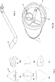
- a surgical device or instrument according to a first embodiment of the invention is designated as a whole with 1.
- the device 1 è configured for inserting a supporting element, in particular a mesh or net, at the vaginal vault to treat the prolapse thereof.
- the device 1 mainly comprises:
- the proximal handpiece 2 in general terms, has elements for actuating the canalizing means 10, the means 4 for applying a staple and the suction system 5, which can be actuated by an operator with his/her hand.
- a connection 13 is provided, which can be connected to a suction system and/or pneumatic power supply existing in the operating environment.
- the connection 13 is equipped with a tap 14, occlusion valve or other element with analogous function.
- the handpiece 2 has a main portion 20 which can be grasped by the user, for example with cylindrical and/or elongated geometry.
- the main body preferably, is hollow inside and it has at least a longitudinal room 30 apt to house the mesh.
- longitudinal direction in the present context, a prevailing development direction of the device 1, and in particular of the main body thereof 3, is meant. Such direction is designated with L in Figure 1A .
- Such direction also corresponds substantially to the direction for inserting and forwarding the main body 3 in the abdomen of the patient.
- the main body 3 does not extend according to one single rectilinear direction, but it has a corrugated development, by extending so as to reproduce an anatomic curve comprised between the lateral wall of the abdomen and the vaginal vault.
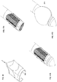
- the main body 3 has a tip-like shaped distal end 31, represented in detail in Figure 3 and shaped so as to ease the insertion of the main body itself inside the abdomen of the patient and the separation/dissection of the tissues gradually met as far as the site of interest, that is the vaginal vault.
- a tip-like shaped distal end 31 represented in detail in Figure 3 and shaped so as to ease the insertion of the main body itself inside the abdomen of the patient and the separation/dissection of the tissues gradually met as far as the site of interest, that is the vaginal vault.
- such portion 31 is shaped like a trilobate tip.
- Such tip 31 is placed in the position immediately distal to the above-mentioned balloon 11.
- the tip-like shaped portion 31 preferably is hollow and however it contributes to define an opening or side door 32 of the main body 3 the function thereof will be explained hereinafter.
- the balloon 11 can be selectively inflated and deflated, alternatively, thanks to a joint to the above-mentioned connection 13.
- a pneumatic supply channel 32 is obtained, leading distally into a door or hole 33 for feeding the balloon 11.
- a door or hole 33 is arranged at a side skirt of the main body 3.
- the channel 32 is also fed with inflating air of the balloon 11 by means of actuating means 21 which can be actuated by the operator and arranged on the handpiece 2.
- the actuating means 21 comprises an actuation element 22 shaped like a button, advantageously elongated in L direction for an easier handling.
- the button 22 can be actuated by means of a pressure applied in a direction T substantially orthogonal to the prevailing development direction L of the handpiece 2, of the main body 3 and, generally, of the device 1. In this way, the button 21 can be actuated with the fingers of the hand while this is holding the handpiece 2.
- Contrast elastic means is associated to the button 22, in the present example two compression helical springs 23. In the herein considered preferred configuration, a pressing action on the button 22 determines the inflating of the balloon 11.
- the springs 23 bring back the button itself in a rest configuration corresponding to the deflating configuration of the balloon 11.
- the operator can actuate alternatively the balloon 11 from a maximum encumbrance configuration, that is inflated and radially projecting from the main body 3, to a minimal encumbrance configuration, that is deflated and substantially adhering to the main body itself.
- the inflating air can be sent inside the channel 32 and then to the balloon 11 by associating sealing components to the actuating means 21 allowing to make them to act like a kind of small pump.
- the means 21 can act together with an air chamber 25.
- Embodiment variants can provide that the channel 32 is placed selectively in communication with the connection 13, in this case used for feeding air under pressure of the system.
- the canalizing means can also provide elements different from the above-mentioned balloon 11, however apt to assume, alternatively, a minimal encumbrance configuration and a maximum encumbrance configuration.
- Embodiment variants can provide deformable elements in the sense that they have arrangements and/or mechanical connections suitable to allow the assumption of the above-mentioned minimum and maximum encumbrance configurations.
- the means 4 for applying a staple comprises an operative, or guiding channel 41 extending within the main body 3 for carrying the staple as far as a distal exit door or nozzle 42 which opens at the opening 32 of the main body 3.
- a thread or other point-pushing element 43 is mobile, the latter preferably equipped with a widened actuation proximal portion 44.
- the staple can be inserted into the device 1 at a loader thereof, which by simplicity has not been represented and which is suitable to include a plurality of staples and to feed them in sequence, upon control, inside the channel 41. In a simpler variant, a plurality of points is loaded directly inside the channel 41.
- a proximal actuation or driver 24 is a button arranged at the longitudinal end of the handpiece 2 and which can be actuated by the operator by means of a pressure substantially oriented in longitudinal direction L.
- the button 24 is configured for being activated by the palm of the hand.
- the suction system 5 too can be joined selectively to the same above-mentioned connection 13.
- the system includes an operative channel 51, for example visible in Figure 4A and extending longitudinally inside the main body 3 as far as the distal opening 32 thereof.
- the suction activation can be controlled directly by actuating the proximal tap 14 or by means of other dedicated element.
- Figure 7 shows an example of mesh, herein designated with M, in the configuration wherein it is arranged inside the room 30 of the main body 3.
- the mesh has a basic shape with polygonal basis, in particular with rectangular strip, and it is housed inside the room 30 with the longitudinal margins folded towards inside.
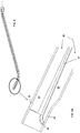
- Figures 6A to 6D exemplify the modes thereby the mesh M is arranged inside the device 1.
- a long for example about 40 cm
- flexible pliers is inserted, so as to cover the whole inner room 30 of the main body 3.
- the pliers grasps a pre-cut portion of mesh.
- the pliers is then driven by dragging the mesh inside the main body 3 and, once reached again the distal end, the mesh is released from the pliers so as to let it to be trapped inside the room 30.
- the mesh is inserted in the main body 3 of the device 1 already in the assembling step and the instrument is sold ready for use.
- the mesh is pre-cut in portions of about 2.5cmx30cm and folded on itself to minimize the width thereof. As it is deformable, the mesh substantially assumes the shape of the room 30 housing it.
- Figures 8A to 8C and 9A to 9B represent indeed the device 1 with the mesh M housed inside thereof.
- the trilobate tip 21 eases the insertion of the device 1 through the cutaneous incision and it allows the separation of the peritoneum during the forwarding of the instrument inside the abdomen. Such separation is eased even by the repeated inflation of the balloon 11 actuated by the button 22.
- the suction of the system 5 is actuated and the vaginal wall is sucked back inside the opening 32 so as to make it to adhere against the mesh M.
- the point-pushing button 24 is then actuated with the palm of the hand and the thread 43 forces the point, for example made of titanium and designated with P in Figure 9B , through the output section 42.
- the latter advantageously, has a shape with strict radius of curvature, so as to impress a plastic deformation at the point outgoing from the operative channel 41 and which is induced to assume a circular shape, by grasping both the vaginal wall and the mesh.
- the instrument is then extracted from the patient and, whereas an end of the mesh remains fixed to the vaginal wall, the other one, once having extracted the instrument, is fastened to the abdominal muscles thus by implementing a so-called procedure of " Pelvic Organ Prolapse Suspension " (POPS).
- POPS Pelvic Organ Prolapse Suspension
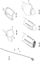
- Figures 10 to 13C relate to a second preferred embodiment of the device of the invention, herein designated as a whole with 100.
- the canalizing means designated with 110, include a plurality of selectively reversibly deformable elements 111 for passing from the above-mentioned maximum encumbrance configuration to the minimum encumbrance one and viceversa.
- deformable elements 111 are three and each one preferably in form of bar, in particular flat and with substantially rectangular plan profile.
- the bars 111 are made of plastic material. Each bar 111 is connected, at its own first proximal end, to the distal end of an actuating shaft 112.
- each bar 111 is constrained on a contrast element 113. This latter abuts onto, and thus is locked to, a corresponding inner profile, not shown, of the main body 103.
- the shaft 112 is slidingly housed inside an inner room 138 of the main body 103. Preferably, it is flexible to follow the longitudinal profile of the main body 103.
- the whole group of the shaft 112, of the elements 111 and of the contrast 113 can be implemented integral.
- each bar 111 outgoes from a respective slot 133 of the main body 103.
- the slots 133 are arranged laterally to an opening or distal door 132 of the main body 103 with function analogous to the already described one.
- the deformation of the bars 111 is induced by pushing longitudinally the shaft 112 by means of a proximal actuation 121 of lever-like type.
- the action onto the lever 121 is applied in substantially longitudinal direction and transmitted to the shaft 112 by means of mechanical connections of type known on itself.
- elastic means can be associated, apt to bring it back to a rest configuration (back, in the present embodiment) corresponding to a minimal encumbrance configuration of the means 110.
- the minimum encumbrance configuration of the elements 111 is shown in Figures 12B and 13B .
- a wrapping membrane 14 for example made of silicone, can be applied to prevent the entry of biological residues into the slots 133 and to apply the inserting action in a more effective way without damaging the surrounding tissues.
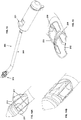
- Figures 14 to 17C relate to a third preferred embodiment of the invention device, herein designated as a whole with 200.
- the device 200 provides canalizing means 210 with structure similar to that of the above-described second embodiment, wherein however the bars are replaced by longitudinal filiform elements 211, preferably made of metal.
- the filiform elements 211 are deformable selectively and in a reversible way, in a way analogous to what already illustrated for the bars, in particular by means of a proximal lever-like actuation herein designated with 221.
- the filiform elements 211 can be associated, for greater stability, to transversal filiform elements, or crossbeams 217. Furthermore, even such elements 211 and 217 can be wrapped in a membrane 214 of the already described type.
- the filiform elements 211 are associated to an actuation shaft analogous to the already described one, sliding in an operative channel 238 of the main body 203. Furthermore, at its own distal end they are constrained to a gripping element 213 in form of stirrup or sleeve. The latter is suitable to engage a corresponding seat 239 of the main body 203, by remaining retained by interlocking inside thereof.
- the filiform elements in case in the form of grid associated to the presence of crossbeams 217, outgo from a common opening 233, preferably obtained on the side skirt of the main body 203 on opposite side with respect to an opening 232 thereof with function analogous to the already described one.
Landscapes
- Health & Medical Sciences (AREA)
- Life Sciences & Earth Sciences (AREA)
- Surgery (AREA)
- General Health & Medical Sciences (AREA)
- Public Health (AREA)
- Biomedical Technology (AREA)
- Heart & Thoracic Surgery (AREA)
- Veterinary Medicine (AREA)
- Engineering & Computer Science (AREA)
- Animal Behavior & Ethology (AREA)
- Molecular Biology (AREA)
- Nuclear Medicine, Radiotherapy & Molecular Imaging (AREA)
- Medical Informatics (AREA)
- Gynecology & Obstetrics (AREA)
- Pregnancy & Childbirth (AREA)
- Reproductive Health (AREA)
- Cardiology (AREA)
- Oral & Maxillofacial Surgery (AREA)
- Transplantation (AREA)
- Vascular Medicine (AREA)
- Surgical Instruments (AREA)
Claims (20)
- Chirurgisches Gerät (1; 100; 200), das konfiguriert ist, um ein Stützelement (M), vorzugsweise ein Netz ("mesh"), an dem Scheidengewölbe, an dem Rektum oder an irgendeinem anderen Beckenorgan einzuführen, um dessen Prolaps zu behandeln, wobei das Gerät umfasst:einen proximalen Griff (2), der von einem Operateur gehalten werden kann;einen länglichen Hauptkörper (3), der mit dem Griff (2) verbunden oder fest verbindbar ist und diesbezüglich distal angeordnet ist, wobei der Hauptkörper (3) geeignet ist, perkutan durch den Unterleib hoch zu dem Scheidengewölbe oder dem anderen Organ eingeführt zu werden;Kanalisiermittel (10), die an einem distalen Endbereich (31) des Hauptkörpers (3) angeordnet sind und an dem proximalen Griff (2) betreibbar sind, wobei die Kanalisiermittel (3) geeignet sind, alternativ eine minimale Belastungskonfiguration und eine maximale Belastungskonfiguration anzunehmen, geeignet zum Begünstigen der Trennung von Unterleibgeweben während des Einführens des Hauptkörpers (3) durch den Unterleib, dadurch gekennzeichnet, dass der Hauptkörper (3) einen länglichen Raum (30) aufweist, der geeignet ist, das Stützelement (M) zu beherbergen.
- Gerät (1; 100; 200) nach Anspruch 1, wobei der Hauptkörper (3) eine Wellenform aufweist, die sich länglich gemäß einem Profil erstreckt, das geeignet ist, eine anatomische Kurve wiederzugeben, die zwischen der seitlichen Wand des Unterleibs und dem Scheidengewölbe vorhanden ist.
- Gerät (1; 100; 200) nach einem der vorhergehenden Ansprüche, wobei der Hauptkörper (3) ein distales Ende mit einer Spitzenform (31) aufweist, insbesondere dreilappig, geeignet zum Begünstigen des Einführens des Geräts durch die Unterleibgewebe.
- Gerät (1) nach einem der vorhergehenden Ansprüche, wobei die Konfigurationen einer maximalen und einer minimalen Belastung der Kanalisiermittel (10) einer maximalen Erweiterung beziehungsweise einer minimalen Erweiterung davon entsprechen, in einer Querrichtung senkrecht zu einer longitudinalen Richtung einer Vorwärtsbewegung des Hauptkörpers (3) durch den Unterleib.
- Gerät (1) nach einem der vorhergehenden Ansprüche, wobei die Kanalisiermittel (10) ein oder mehrere Elemente (11) umfassen, die selektiv deformierbar sind, um die Konfigurationen einer maximalen und einer minimalen Belastung anzunehmen.
- Gerät (1) nach einem der vorhergehenden Ansprüche, wobei die Kanalisiermittel (10) eine Membran oder einen Ballon (11) umfassen, welcher selektiv aufblasbar ist.
- Gerät (100; 200) nach einem der Ansprüche 1 bis 5, wobei die Kanalisiermittel (110) eine Vielzahl reversibel deformierbarer Elemente (111) umfassen, die vorzugsweise konfiguriert sind, um selektiv jedes aus einer jeweiligen Öffnung (133) herauszuführen, die in einer Seitenschürze des Hauptkörpers (103) vorgesehen ist, um die maximale Belastungskonfiguration anzunehmen.
- Gerät (100; 200) nach dem vorhergehenden Anspruch, wobei die deformierbaren Elemente eine Vielzahl longitudinaler Balkenelemente (111) umfassen, vorzugsweise aus Kunststoffmaterial gefertigt, oder eine Vielzahl longitudinaler fadenförmiger Elemente (211), vorzugsweise aus Metall gefertigt.
- Gerät (200) nach Anspruch 7 oder 8, wobei die deformierbaren Elemente eine Gitterkonfiguration aufweisen, die durch longitudinale Elemente (211) und transversale Elemente (217) gebildet ist.
- Gerät (100; 200) nach einem der Ansprüche 7 bis 9, das eine Welle (112) zum Betätigen der reversibel deformierbaren Elemente (111) umfasst, wobei die Betätigungswelle (112) sich longitudinal innerhalb des Hauptkörpers (103) erstreckt, wobei vorzugsweise die reversibel deformierbaren Elemente (111) distal mit Bezug auf die Betätigungswelle (112) angeordnet und daran gesichert sind.
- Gerät (1; 100; 200) nach einem der vorhergehenden Ansprüche, welches Mittel (21; 121) zum Betätigen der Kanalisiermittel (10) umfasst, wobei die Betätigungsmittel (21; 121) an dem proximalen Griff (2) angeordnet sind, von einem Operateur aktiviert werden können und vorzugsweise einen Hebel oder eine Taste umfassen, wobei die Betätigungsmittel (21; 121) vorzugsweise konfiguriert sind, um durch eine Kraft aktiviert zu werden, die in einer Richtung transversal oder longitudinal mit Bezug auf das Gerät angewendet wird.
- Gerät (1; 100; 200) nach dem vorhergehenden Anspruch, wobei die Betägigungsmittel (21) ein Betätigungselement (22) und ein elastisches Gegenmittel (23) umfassen, das damit assoziiert ist, wobei das elastische Gegenmittel (23) geeignet ist, das Betätigungsmittel (22) in eine Ruhekonfiguration zurückzubringen, die der minimalen Belastungskonfiguration der Kanalisiermittel (10) entspricht.
- Gerät (1; 100; 200) nach einem der vorhergehenden Ansprüche, das Mittel (4) zum Zufügen einer Heftung oder eines Befestigungspunktes des Stützelements an dem Scheidengewölbe oder dem anderen Organ umfasst.
- Gerät (1; 100; 200) nach dem vorhergehenden Anspruch, wobei die Mittel zum Zufügen einer Heftung einen Führungskanal (41) für die Heftung umfassen, der sich in dem Hauptkörper (3) erstreckt und vorzugsweise mit einer Ausgangsöffnung (42) des Punktes ausgestattet ist, der an einer distalen Öffnung (32) des Hauptkörpers (3) angeordnet ist, vorzugsweise einer Seitenöffnung.
- Gerät (1; 100; 200) nach Anspruch 13 oder 14, wobei die Mittel (4) zum Zufügen einer Heftung eine Antriebseinrichtung (24) umfassen, die von einem Operateur betätigt werden kann und an dem proximalen Griff (2) angeordnet ist, wobei die Antriebseinrichtung (24) vorzugsweise konfiguriert ist, um durch einen Druck aktiviert zu werden, der in einer longitudinalen Richtung des Geräts aufgebracht wird.
- Gerät (1; 100; 200) nach dem vorhergehenden Anspruch, wobei die proximale Antriebseinrichtung (24) eine Taste umfasst, die vorzugsweise konfiguriert ist, um durch die Fläche der Hand aktiviert zu werden.
- Gerät (1; 100; 200) nach einem der vorhergehenden Ansprüche, das weiterhin ein Saugsystem (5) umfasst, das auf eine solche Weise konfiguriert ist, dass es eine Saugwirkung auf das Scheidengewölbe oder das andere Organ an einem distalen Bereich des Hauptkörpers (3) aufbringt, insbesondere an einer vorzugsweise seitlichen Öffnung (32) davon.
- Gerät (1; 100; 200) nach einem der vorhergehenden Ansprüche, wobei die Betätigungsmittel (10), die Mittel zum Zuführen einer Heftung (4) und/oder die Saugmittel (5) einen Betriebskanal (37, 41, 51) umfassen, der sich longitudinal innerhalb des Hauptkörpers (3) erstreckt.
- Gerät (1) nach einem der vorhergehenden Ansprüche, das eine Verbindung (13) für eine Energieversorgung und/oder ein pneumatisches Saugsystem umfasst, vorzugsweise angeordnet an dem proximalen Griff (2).
- Chirurgisches System mit einem Gerät (1; 100; 200) nach einem der vorhergehenden Ansprüche und einem Stützelement, vorzugsweise einem Netz ("mesh") (M), das in den Hauptkörper (3) eingeführt ist.
Applications Claiming Priority (2)
| Application Number | Priority Date | Filing Date | Title |
|---|---|---|---|
| ITUB2015A000783A ITUB20150783A1 (it) | 2015-05-21 | 2015-05-21 | Dispositivo chirurgico |
| PCT/IB2016/052946 WO2016185422A1 (en) | 2015-05-21 | 2016-05-19 | Surgical device for implanting a mesh |
Publications (2)
| Publication Number | Publication Date |
|---|---|
| EP3297550A1 EP3297550A1 (de) | 2018-03-28 |
| EP3297550B1 true EP3297550B1 (de) | 2018-11-28 |
Family
ID=54064420
Family Applications (1)
| Application Number | Title | Priority Date | Filing Date |
|---|---|---|---|
| EP16735683.1A Not-in-force EP3297550B1 (de) | 2015-05-21 | 2016-05-19 | Chirurgische vorrichtung zur implantation eines netzes |
Country Status (3)
| Country | Link |
|---|---|
| EP (1) | EP3297550B1 (de) |
| IT (1) | ITUB20150783A1 (de) |
| WO (1) | WO2016185422A1 (de) |
Families Citing this family (1)
| Publication number | Priority date | Publication date | Assignee | Title |
|---|---|---|---|---|
| CN108524059B (zh) * | 2018-05-03 | 2025-06-13 | 上海市第一妇婴保健院 | 沿圆韧带至髂前上棘前方腹股沟韧带的悬吊手术方法及装置治疗盆腔器官脱垂 |
Family Cites Families (5)
| Publication number | Priority date | Publication date | Assignee | Title |
|---|---|---|---|---|
| IL103442A (en) * | 1991-10-18 | 1998-01-04 | Ethicon Inc | Installs the adhesive buffer |
| US6592602B1 (en) * | 1999-10-08 | 2003-07-15 | General Surgical Innovations, Inc. | Balloon dissection apparatus |
| CA2715740C (en) * | 2008-02-18 | 2014-05-27 | Polytouch Medical Ltd. | A device and method for deploying and attaching a patch to a biological tissue |
| ES2518491T3 (es) * | 2009-09-01 | 2014-11-05 | Coloplast A/S | Sistema de reparación mínimamente invasiva de prolapso de órgano pélvico |
| US9339365B2 (en) * | 2011-07-07 | 2016-05-17 | David D. Park | Device and method for delivering grafts |
-
2015
- 2015-05-21 IT ITUB2015A000783A patent/ITUB20150783A1/it unknown
-
2016
- 2016-05-19 EP EP16735683.1A patent/EP3297550B1/de not_active Not-in-force
- 2016-05-19 WO PCT/IB2016/052946 patent/WO2016185422A1/en not_active Ceased
Non-Patent Citations (1)
| Title |
|---|
| None * |
Also Published As
| Publication number | Publication date |
|---|---|
| WO2016185422A1 (en) | 2016-11-24 |
| EP3297550A1 (de) | 2018-03-28 |
| ITUB20150783A1 (it) | 2016-11-21 |
Similar Documents
| Publication | Publication Date | Title |
|---|---|---|
| JP2677947B2 (ja) | 腹腔鏡を用いたヘルニア治療用の解剖学的腔を形成する装置及び方法及びこれに使用するパッチ | |
| JP4795819B2 (ja) | バルーン切開装置 | |
| JP4282242B2 (ja) | 外科手術で使用するための特殊形状のバルーン装置およびその使用方法 | |
| US10208925B2 (en) | Soft conformal laparoscopic instrument | |
| US6562048B1 (en) | Deformable conduits and methods for shunting bodily fluid during surgery | |
| JP5241762B2 (ja) | バルーン先端部カニューレを備えたバルーン切開器具 | |
| CA2350101C (en) | Apparatus and method for dissecting and retracting elongate structures | |
| EP2519160B1 (de) | Werkzeuge zur behandlung von beckenerkrankungen | |
| US10478326B2 (en) | Devices and methods facilitating sleeve gastrectomy procedures | |
| US20090204130A1 (en) | Method of Performing Transgastric Ventral Hernia Repair and Tissue Anchors and Deployment Devices Therefor | |
| JP2009279428A (ja) | 内視鏡的な器官牽引システムおよびその使用方法 | |
| MXPA04009612A (es) | Aplicador para anastomosis de un solo lumen para sujetador autodesplegable. | |
| US20170150957A9 (en) | Inflatable laparoscopic retractor for atraumatic retraction in abdominal surgery | |
| JP2003524471A (ja) | 視覚化を向上させたバルーン切開装置 | |
| WO2016185422A1 (en) | Surgical device for implanting a mesh | |
| JP2013102836A (ja) | 腹腔鏡手術用の蛇腹管型圧排器 |
Legal Events
| Date | Code | Title | Description |
|---|---|---|---|
| STAA | Information on the status of an ep patent application or granted ep patent |
Free format text: STATUS: THE INTERNATIONAL PUBLICATION HAS BEEN MADE |
|
| PUAI | Public reference made under article 153(3) epc to a published international application that has entered the european phase |
Free format text: ORIGINAL CODE: 0009012 |
|
| STAA | Information on the status of an ep patent application or granted ep patent |
Free format text: STATUS: REQUEST FOR EXAMINATION WAS MADE |
|
| 17P | Request for examination filed |
Effective date: 20171108 |
|
| AK | Designated contracting states |
Kind code of ref document: A1 Designated state(s): AL AT BE BG CH CY CZ DE DK EE ES FI FR GB GR HR HU IE IS IT LI LT LU LV MC MK MT NL NO PL PT RO RS SE SI SK SM TR |
|
| AX | Request for extension of the european patent |
Extension state: BA ME |
|
| GRAP | Despatch of communication of intention to grant a patent |
Free format text: ORIGINAL CODE: EPIDOSNIGR1 |
|
| STAA | Information on the status of an ep patent application or granted ep patent |
Free format text: STATUS: GRANT OF PATENT IS INTENDED |
|
| DAX | Request for extension of the european patent (deleted) | ||
| INTG | Intention to grant announced |
Effective date: 20180608 |
|
| DAV | Request for validation of the european patent (deleted) | ||
| GRAS | Grant fee paid |
Free format text: ORIGINAL CODE: EPIDOSNIGR3 |
|
| GRAA | (expected) grant |
Free format text: ORIGINAL CODE: 0009210 |
|
| STAA | Information on the status of an ep patent application or granted ep patent |
Free format text: STATUS: THE PATENT HAS BEEN GRANTED |
|
| AK | Designated contracting states |
Kind code of ref document: B1 Designated state(s): AL AT BE BG CH CY CZ DE DK EE ES FI FR GB GR HR HU IE IS IT LI LT LU LV MC MK MT NL NO PL PT RO RS SE SI SK SM TR |
|
| REG | Reference to a national code |
Ref country code: CH Ref legal event code: EP |
|
| REG | Reference to a national code |
Ref country code: AT Ref legal event code: REF Ref document number: 1069313 Country of ref document: AT Kind code of ref document: T Effective date: 20181215 |
|
| REG | Reference to a national code |
Ref country code: DE Ref legal event code: R096 Ref document number: 602016007649 Country of ref document: DE |
|
| REG | Reference to a national code |
Ref country code: IE Ref legal event code: FG4D |
|
| REG | Reference to a national code |
Ref country code: NL Ref legal event code: MP Effective date: 20181128 |
|
| REG | Reference to a national code |
Ref country code: LT Ref legal event code: MG4D |
|
| REG | Reference to a national code |
Ref country code: AT Ref legal event code: MK05 Ref document number: 1069313 Country of ref document: AT Kind code of ref document: T Effective date: 20181128 |
|
| PG25 | Lapsed in a contracting state [announced via postgrant information from national office to epo] |
Ref country code: NO Free format text: LAPSE BECAUSE OF FAILURE TO SUBMIT A TRANSLATION OF THE DESCRIPTION OR TO PAY THE FEE WITHIN THE PRESCRIBED TIME-LIMIT Effective date: 20190228 Ref country code: LT Free format text: LAPSE BECAUSE OF FAILURE TO SUBMIT A TRANSLATION OF THE DESCRIPTION OR TO PAY THE FEE WITHIN THE PRESCRIBED TIME-LIMIT Effective date: 20181128 Ref country code: BG Free format text: LAPSE BECAUSE OF FAILURE TO SUBMIT A TRANSLATION OF THE DESCRIPTION OR TO PAY THE FEE WITHIN THE PRESCRIBED TIME-LIMIT Effective date: 20190228 Ref country code: FI Free format text: LAPSE BECAUSE OF FAILURE TO SUBMIT A TRANSLATION OF THE DESCRIPTION OR TO PAY THE FEE WITHIN THE PRESCRIBED TIME-LIMIT Effective date: 20181128 Ref country code: LV Free format text: LAPSE BECAUSE OF FAILURE TO SUBMIT A TRANSLATION OF THE DESCRIPTION OR TO PAY THE FEE WITHIN THE PRESCRIBED TIME-LIMIT Effective date: 20181128 Ref country code: HR Free format text: LAPSE BECAUSE OF FAILURE TO SUBMIT A TRANSLATION OF THE DESCRIPTION OR TO PAY THE FEE WITHIN THE PRESCRIBED TIME-LIMIT Effective date: 20181128 Ref country code: ES Free format text: LAPSE BECAUSE OF FAILURE TO SUBMIT A TRANSLATION OF THE DESCRIPTION OR TO PAY THE FEE WITHIN THE PRESCRIBED TIME-LIMIT Effective date: 20181128 Ref country code: IS Free format text: LAPSE BECAUSE OF FAILURE TO SUBMIT A TRANSLATION OF THE DESCRIPTION OR TO PAY THE FEE WITHIN THE PRESCRIBED TIME-LIMIT Effective date: 20190328 Ref country code: AT Free format text: LAPSE BECAUSE OF FAILURE TO SUBMIT A TRANSLATION OF THE DESCRIPTION OR TO PAY THE FEE WITHIN THE PRESCRIBED TIME-LIMIT Effective date: 20181128 |
|
| PG25 | Lapsed in a contracting state [announced via postgrant information from national office to epo] |
Ref country code: PT Free format text: LAPSE BECAUSE OF FAILURE TO SUBMIT A TRANSLATION OF THE DESCRIPTION OR TO PAY THE FEE WITHIN THE PRESCRIBED TIME-LIMIT Effective date: 20190328 Ref country code: RS Free format text: LAPSE BECAUSE OF FAILURE TO SUBMIT A TRANSLATION OF THE DESCRIPTION OR TO PAY THE FEE WITHIN THE PRESCRIBED TIME-LIMIT Effective date: 20181128 Ref country code: GR Free format text: LAPSE BECAUSE OF FAILURE TO SUBMIT A TRANSLATION OF THE DESCRIPTION OR TO PAY THE FEE WITHIN THE PRESCRIBED TIME-LIMIT Effective date: 20190301 Ref country code: AL Free format text: LAPSE BECAUSE OF FAILURE TO SUBMIT A TRANSLATION OF THE DESCRIPTION OR TO PAY THE FEE WITHIN THE PRESCRIBED TIME-LIMIT Effective date: 20181128 Ref country code: SE Free format text: LAPSE BECAUSE OF FAILURE TO SUBMIT A TRANSLATION OF THE DESCRIPTION OR TO PAY THE FEE WITHIN THE PRESCRIBED TIME-LIMIT Effective date: 20181128 |
|
| PG25 | Lapsed in a contracting state [announced via postgrant information from national office to epo] |
Ref country code: NL Free format text: LAPSE BECAUSE OF FAILURE TO SUBMIT A TRANSLATION OF THE DESCRIPTION OR TO PAY THE FEE WITHIN THE PRESCRIBED TIME-LIMIT Effective date: 20181128 |
|
| PG25 | Lapsed in a contracting state [announced via postgrant information from national office to epo] |
Ref country code: IT Free format text: LAPSE BECAUSE OF FAILURE TO SUBMIT A TRANSLATION OF THE DESCRIPTION OR TO PAY THE FEE WITHIN THE PRESCRIBED TIME-LIMIT Effective date: 20181128 Ref country code: DK Free format text: LAPSE BECAUSE OF FAILURE TO SUBMIT A TRANSLATION OF THE DESCRIPTION OR TO PAY THE FEE WITHIN THE PRESCRIBED TIME-LIMIT Effective date: 20181128 Ref country code: CZ Free format text: LAPSE BECAUSE OF FAILURE TO SUBMIT A TRANSLATION OF THE DESCRIPTION OR TO PAY THE FEE WITHIN THE PRESCRIBED TIME-LIMIT Effective date: 20181128 Ref country code: PL Free format text: LAPSE BECAUSE OF FAILURE TO SUBMIT A TRANSLATION OF THE DESCRIPTION OR TO PAY THE FEE WITHIN THE PRESCRIBED TIME-LIMIT Effective date: 20181128 |
|
| REG | Reference to a national code |
Ref country code: DE Ref legal event code: R097 Ref document number: 602016007649 Country of ref document: DE |
|
| PG25 | Lapsed in a contracting state [announced via postgrant information from national office to epo] |
Ref country code: SK Free format text: LAPSE BECAUSE OF FAILURE TO SUBMIT A TRANSLATION OF THE DESCRIPTION OR TO PAY THE FEE WITHIN THE PRESCRIBED TIME-LIMIT Effective date: 20181128 Ref country code: SM Free format text: LAPSE BECAUSE OF FAILURE TO SUBMIT A TRANSLATION OF THE DESCRIPTION OR TO PAY THE FEE WITHIN THE PRESCRIBED TIME-LIMIT Effective date: 20181128 Ref country code: RO Free format text: LAPSE BECAUSE OF FAILURE TO SUBMIT A TRANSLATION OF THE DESCRIPTION OR TO PAY THE FEE WITHIN THE PRESCRIBED TIME-LIMIT Effective date: 20181128 Ref country code: EE Free format text: LAPSE BECAUSE OF FAILURE TO SUBMIT A TRANSLATION OF THE DESCRIPTION OR TO PAY THE FEE WITHIN THE PRESCRIBED TIME-LIMIT Effective date: 20181128 |
|
| PLBE | No opposition filed within time limit |
Free format text: ORIGINAL CODE: 0009261 |
|
| STAA | Information on the status of an ep patent application or granted ep patent |
Free format text: STATUS: NO OPPOSITION FILED WITHIN TIME LIMIT |
|
| 26N | No opposition filed |
Effective date: 20190829 |
|
| REG | Reference to a national code |
Ref country code: CH Ref legal event code: PL |
|
| PG25 | Lapsed in a contracting state [announced via postgrant information from national office to epo] |
Ref country code: MC Free format text: LAPSE BECAUSE OF FAILURE TO SUBMIT A TRANSLATION OF THE DESCRIPTION OR TO PAY THE FEE WITHIN THE PRESCRIBED TIME-LIMIT Effective date: 20181128 Ref country code: CH Free format text: LAPSE BECAUSE OF NON-PAYMENT OF DUE FEES Effective date: 20190531 Ref country code: LI Free format text: LAPSE BECAUSE OF NON-PAYMENT OF DUE FEES Effective date: 20190531 |
|
| REG | Reference to a national code |
Ref country code: BE Ref legal event code: MM Effective date: 20190531 |
|
| PG25 | Lapsed in a contracting state [announced via postgrant information from national office to epo] |
Ref country code: LU Free format text: LAPSE BECAUSE OF NON-PAYMENT OF DUE FEES Effective date: 20190519 |
|
| PG25 | Lapsed in a contracting state [announced via postgrant information from national office to epo] |
Ref country code: TR Free format text: LAPSE BECAUSE OF FAILURE TO SUBMIT A TRANSLATION OF THE DESCRIPTION OR TO PAY THE FEE WITHIN THE PRESCRIBED TIME-LIMIT Effective date: 20181128 |
|
| PG25 | Lapsed in a contracting state [announced via postgrant information from national office to epo] |
Ref country code: IE Free format text: LAPSE BECAUSE OF NON-PAYMENT OF DUE FEES Effective date: 20190519 |
|
| PG25 | Lapsed in a contracting state [announced via postgrant information from national office to epo] |
Ref country code: BE Free format text: LAPSE BECAUSE OF NON-PAYMENT OF DUE FEES Effective date: 20190531 |
|
| PG25 | Lapsed in a contracting state [announced via postgrant information from national office to epo] |
Ref country code: FR Free format text: LAPSE BECAUSE OF NON-PAYMENT OF DUE FEES Effective date: 20190531 |
|
| GBPC | Gb: european patent ceased through non-payment of renewal fee |
Effective date: 20200519 |
|
| PG25 | Lapsed in a contracting state [announced via postgrant information from national office to epo] |
Ref country code: GB Free format text: LAPSE BECAUSE OF NON-PAYMENT OF DUE FEES Effective date: 20200519 |
|
| PG25 | Lapsed in a contracting state [announced via postgrant information from national office to epo] |
Ref country code: CY Free format text: LAPSE BECAUSE OF FAILURE TO SUBMIT A TRANSLATION OF THE DESCRIPTION OR TO PAY THE FEE WITHIN THE PRESCRIBED TIME-LIMIT Effective date: 20181128 |
|
| PG25 | Lapsed in a contracting state [announced via postgrant information from national office to epo] |
Ref country code: MT Free format text: LAPSE BECAUSE OF FAILURE TO SUBMIT A TRANSLATION OF THE DESCRIPTION OR TO PAY THE FEE WITHIN THE PRESCRIBED TIME-LIMIT Effective date: 20181128 Ref country code: HU Free format text: LAPSE BECAUSE OF FAILURE TO SUBMIT A TRANSLATION OF THE DESCRIPTION OR TO PAY THE FEE WITHIN THE PRESCRIBED TIME-LIMIT; INVALID AB INITIO Effective date: 20160519 |
|
| PG25 | Lapsed in a contracting state [announced via postgrant information from national office to epo] |
Ref country code: SI Free format text: LAPSE BECAUSE OF FAILURE TO SUBMIT A TRANSLATION OF THE DESCRIPTION OR TO PAY THE FEE WITHIN THE PRESCRIBED TIME-LIMIT Effective date: 20181128 |
|
| PG25 | Lapsed in a contracting state [announced via postgrant information from national office to epo] |
Ref country code: MK Free format text: LAPSE BECAUSE OF FAILURE TO SUBMIT A TRANSLATION OF THE DESCRIPTION OR TO PAY THE FEE WITHIN THE PRESCRIBED TIME-LIMIT Effective date: 20181128 |
|
| PGFP | Annual fee paid to national office [announced via postgrant information from national office to epo] |
Ref country code: DE Payment date: 20240619 Year of fee payment: 9 |
|
| REG | Reference to a national code |
Ref country code: DE Ref legal event code: R119 Ref document number: 602016007649 Country of ref document: DE |
|
| PG25 | Lapsed in a contracting state [announced via postgrant information from national office to epo] |
Ref country code: DE Free format text: LAPSE BECAUSE OF NON-PAYMENT OF DUE FEES Effective date: 20251202 |