EP3297224B1 - Preventing data traffic loops associated with designated forwarder selection - Google Patents
Preventing data traffic loops associated with designated forwarder selection Download PDFInfo
- Publication number
- EP3297224B1 EP3297224B1 EP16198982.7A EP16198982A EP3297224B1 EP 3297224 B1 EP3297224 B1 EP 3297224B1 EP 16198982 A EP16198982 A EP 16198982A EP 3297224 B1 EP3297224 B1 EP 3297224B1
- Authority
- EP
- European Patent Office
- Prior art keywords
- identifier
- provider edge
- identifiers
- devices
- route
- Prior art date
- Legal status (The legal status is an assumption and is not a legal conclusion. Google has not performed a legal analysis and makes no representation as to the accuracy of the status listed.)
- Active
Links
- 238000000034 method Methods 0.000 claims description 48
- 238000004590 computer program Methods 0.000 claims 1
- 230000015654 memory Effects 0.000 description 12
- 238000012545 processing Methods 0.000 description 9
- 238000002330 electrospray ionisation mass spectrometry Methods 0.000 description 7
- 238000010586 diagram Methods 0.000 description 6
- 238000004891 communication Methods 0.000 description 5
- 230000006870 function Effects 0.000 description 3
- 230000005540 biological transmission Effects 0.000 description 2
- 238000001514 detection method Methods 0.000 description 2
- 238000005538 encapsulation Methods 0.000 description 2
- 230000002441 reversible effect Effects 0.000 description 2
- 238000012546 transfer Methods 0.000 description 2
- 230000006399 behavior Effects 0.000 description 1
- 239000000872 buffer Substances 0.000 description 1
- 230000001413 cellular effect Effects 0.000 description 1
- 239000000835 fiber Substances 0.000 description 1
- 230000007774 longterm Effects 0.000 description 1
- 238000012986 modification Methods 0.000 description 1
- 230000004048 modification Effects 0.000 description 1
- 230000003287 optical effect Effects 0.000 description 1
- 230000004044 response Effects 0.000 description 1
- 230000003068 static effect Effects 0.000 description 1
- 230000001052 transient effect Effects 0.000 description 1
Images


Classifications
-
- H—ELECTRICITY
- H04—ELECTRIC COMMUNICATION TECHNIQUE
- H04L—TRANSMISSION OF DIGITAL INFORMATION, e.g. TELEGRAPHIC COMMUNICATION
- H04L45/00—Routing or path finding of packets in data switching networks
- H04L45/56—Routing software
- H04L45/566—Routing instructions carried by the data packet, e.g. active networks
-
- H—ELECTRICITY
- H04—ELECTRIC COMMUNICATION TECHNIQUE
- H04L—TRANSMISSION OF DIGITAL INFORMATION, e.g. TELEGRAPHIC COMMUNICATION
- H04L45/00—Routing or path finding of packets in data switching networks
- H04L45/18—Loop-free operations
-
- H—ELECTRICITY
- H04—ELECTRIC COMMUNICATION TECHNIQUE
- H04L—TRANSMISSION OF DIGITAL INFORMATION, e.g. TELEGRAPHIC COMMUNICATION
- H04L12/00—Data switching networks
- H04L12/28—Data switching networks characterised by path configuration, e.g. LAN [Local Area Networks] or WAN [Wide Area Networks]
- H04L12/46—Interconnection of networks
- H04L12/4641—Virtual LANs, VLANs, e.g. virtual private networks [VPN]
- H04L12/4675—Dynamic sharing of VLAN information amongst network nodes
- H04L12/4679—Arrangements for the registration or de-registration of VLAN attribute values, e.g. VLAN identifiers, port VLAN membership
-
- H—ELECTRICITY
- H04—ELECTRIC COMMUNICATION TECHNIQUE
- H04L—TRANSMISSION OF DIGITAL INFORMATION, e.g. TELEGRAPHIC COMMUNICATION
- H04L45/00—Routing or path finding of packets in data switching networks
- H04L45/02—Topology update or discovery
-
- H—ELECTRICITY
- H04—ELECTRIC COMMUNICATION TECHNIQUE
- H04L—TRANSMISSION OF DIGITAL INFORMATION, e.g. TELEGRAPHIC COMMUNICATION
- H04L45/00—Routing or path finding of packets in data switching networks
- H04L45/14—Routing performance; Theoretical aspects
-
- H—ELECTRICITY
- H04—ELECTRIC COMMUNICATION TECHNIQUE
- H04L—TRANSMISSION OF DIGITAL INFORMATION, e.g. TELEGRAPHIC COMMUNICATION
- H04L45/00—Routing or path finding of packets in data switching networks
- H04L45/24—Multipath
-
- H—ELECTRICITY
- H04—ELECTRIC COMMUNICATION TECHNIQUE
- H04L—TRANSMISSION OF DIGITAL INFORMATION, e.g. TELEGRAPHIC COMMUNICATION
- H04L2101/00—Indexing scheme associated with group H04L61/00
- H04L2101/60—Types of network addresses
- H04L2101/677—Multiple interfaces, e.g. multihomed nodes
-
- H—ELECTRICITY
- H04—ELECTRIC COMMUNICATION TECHNIQUE
- H04L—TRANSMISSION OF DIGITAL INFORMATION, e.g. TELEGRAPHIC COMMUNICATION
- H04L2101/00—Indexing scheme associated with group H04L61/00
- H04L2101/60—Types of network addresses
- H04L2101/695—Types of network addresses using masks or ranges of addresses
-
- H—ELECTRICITY
- H04—ELECTRIC COMMUNICATION TECHNIQUE
- H04L—TRANSMISSION OF DIGITAL INFORMATION, e.g. TELEGRAPHIC COMMUNICATION
- H04L41/00—Arrangements for maintenance, administration or management of data switching networks, e.g. of packet switching networks
- H04L41/08—Configuration management of networks or network elements
-
- H—ELECTRICITY
- H04—ELECTRIC COMMUNICATION TECHNIQUE
- H04L—TRANSMISSION OF DIGITAL INFORMATION, e.g. TELEGRAPHIC COMMUNICATION
- H04L45/00—Routing or path finding of packets in data switching networks
- H04L45/02—Topology update or discovery
- H04L45/04—Interdomain routing, e.g. hierarchical routing
-
- H—ELECTRICITY
- H04—ELECTRIC COMMUNICATION TECHNIQUE
- H04L—TRANSMISSION OF DIGITAL INFORMATION, e.g. TELEGRAPHIC COMMUNICATION
- H04L45/00—Routing or path finding of packets in data switching networks
- H04L45/66—Layer 2 routing, e.g. in Ethernet based MAN's
Definitions
- Multihoming can be useful for connecting a host or network to multiple networks in order to increase reliability, to improve performance, and/or to decrease cost.
- Multihoming is the practice of connecting a host or a network to more than one network.
- a mobile phone may be connected to a Wi-Fi network and a third generation (3G) network simultaneously.
- Multihoming may increase reliability by providing multiple links for packets (e.g., Internet Protocol (IP) packets), so that if a link fails, the packets can be routed through other links.
- IP Internet Protocol
- a multihomed host may be assigned multiple addresses (e.g., IP addresses), one per connected network.
- BGP MPLS Based Ethernet VPN (EVPN); draft-raggarwa-sajassi-12vpn-evpn-04.txt) by Aggarwal et al. for the Internet Engineering Task Force describes procedures for BGP MPLS-based Ethernet VPNs (EVPN). It does not disclose preventing a device from selecting a designated forwarder.
- a new designated forwarder election for the EVPN; draft-ietf-bess-evpn-df-election-00.txt" by Mohanty et al. for the Internet Engineering Task Force describes an improved EVPN Designated Forwarder Election algorithm. It does not disclose preventing a device from selecting a designated forwarder.
- RFC 7432 - BGP MPLS-Based Ethernet VPN by Sajassi et al. for the Internet Engineering Task Force describes procedures for BGP MPLS-based Ethernet VPNs (EVPN). It does not disclose preventing a device from selecting a designated forwarder.
- a device may receive a route identifier that includes a range identifier or a configuration identifier.
- the range identifier may identify a range of broadcast domain identifiers associated with a first device.
- the configuration identifier may identify an Ethernet segment identifier (ESI) configuration of the first device.
- ESE Ethernet segment identifier
- the device may identify the range identifier or the configuration identifier included in the route identifier.
- the device may select a designated forwarder from among multiple devices based on the range of broadcast domain identifiers or based on identifying the configuration identifier.
- the designated forwarder may be the same designated forwarder selected by at least one other device.
- a computer-readable medium may store one or more instructions that, when executed by one or more processors, cause the one or more processors to receive, from multiple provider edge devices, multiple route identifiers that include multiple range identifiers or multiple configuration identifiers.
- the multiple range identifiers or the multiple configuration identifiers may be included in a type-length-value (TLV) element of the multiple route identifiers.
- TLV type-length-value
- a first range identifier included in a first route identifier of the multiple route identifiers may be different than a second range identifier included in a second route identifier of the multiple route identifiers.
- a first configuration identifier included in the first route identifier may be different than a second configuration identifier included in the second route identifier.
- the one or more instructions may cause the one or more processors to extract the multiple range identifiers or the multiple configuration identifiers from the TLV element of the multiple route identifiers.
- the one or more instructions may cause the one or more processors to identify the multiple range identifiers or the multiple configuration identifiers based on extracting the multiple range identifiers or the multiple configuration identifiers.
- the one or more instructions may cause the one or more processors to elect a designated forwarder from among the multiple provider edge devices using an algorithm.
- the algorithm may be the same algorithm used by the multiple provider edge devices to elect the same designated forwarder.
- a method may include receiving, by a device, one or more route identifiers from one or more other devices.
- the one or more route identifiers may include one or more range identifiers associated with one or more ranges of broadcast domain identifiers configured on the one or more other devices, or one or more configuration identifiers associated with one or more ESI configurations of the one or more other devices.
- the method may include identifying, by the device, the one or more range identifiers or the one or more configuration identifiers included in the one or more route identifiers.
- the one or more range identifiers may include at least one range identifier that is different than a range identifier configured on another device.
- the one or more configuration identifiers may include at least one configuration identifier that is different than a configuration identifier configured on another device.
- the method may include selecting, by the device, a designated forwarder from among the device and the one or more other devices.
- Multiple provider edge devices in a multihomed network may be configured to select (e.g., elect) one of the provider edge devices as a designated forwarder to forward network traffic to a customer edge device.
- multihoming may provide redundant connectivity so that connectivity is provided even where a failure in the multihomed network is detected.
- provider edge devices may use an algorithm, V mod N, to select the designated forwarder, where V is the lowest value virtual local area network (VLAN) identifier configured on a provider edge device and N is a quantity of provider edge devices that are multihomed to a particular Ethernet segment (e.g., a set of Ethernet links that connects two or more provider edge devices when a customer edge device is multihomed to the provider edge devices).
- V virtual local area network
- multiple provider edge devices may have different configurations, such as due to a configuration error by a network administrator, due to one or more provider edge devices being a legacy provider edge device, or the like.
- the different configurations may include different VLAN identifiers (e.g., associated with active VLANs).
- Application of the V mod N algorithm when provider edge devices have different VLAN identifiers may cause errors during the selection of a designated forwarder.
- the different configurations may cause provider edge devices to select different designated forwarders. Selection of different designated forwarders may cause a layer 2 loop between the selected designated forwarders.
- a layer 2 loop may occur when multiple provider edge devices in a multihomed environment are selected as designated forwarders, causing the designated forwarders to repeatedly exchange broadcast traffic, unknown unicast traffic, and multicast traffic (BUM traffic) without forwarding the BUM traffic to a customer edge device.
- BUM traffic multicast traffic
- a first provider edge device is configured with VLAN identifiers 4 through 10 and a second provider edge device is configured with VLAN identifiers 5 through 10.
- application of the V mod N algorithm by the first provider edge device may cause the first provider edge device to select the first provider edge device as the designated forwarder and application of the V mod N algorithm by the second provider edge device may cause the second provider edge device to select the second provider edge device as the designated forwarder.
- both the first provider edge device and the second provider edge device have been selected as a designated forwarder, the first and second provider edge devices may attempt to forward BUM traffic to each other, resulting in a layer 2 loop.
- the provider edge devices may have different Ethernet segment identifier (ESI) configurations.
- ESI Ethernet segment identifier
- a first provider edge device may be configured with an ESI per physical device and a second provider edge device may be configured with an ESI per subinterface (or VLAN).
- a mismatch between the ESI configurations of the first provider edge device and the second provider edge device may cause multiple provider edge devices to be selected as designated forwarders. Based on the multiple provider edge devices being selected as designated forwarders, both provider edge devices may forward BUM traffic to each other (e.g., a layer 2 loop).
- provider edge devices may exchange route identifiers that include information identifying VLAN identifiers and ESI configurations. For example, when multihomed provider edge devices advertise type 4 routes to other provider edge devices in a common multihomed environment, one or more type-length-value (TLV) elements may be included with the type 4 route. The provider edge devices may use the TLV elements in the type 4 route to exchange VLAN identifiers and/or configuration identifiers (e.g., that identify whether a provider edge device is configured with an ESI per subinterface or an ESI per physical device).
- TLV type-length-value
- Having provider edge devices exchange route identifiers that include VLAN identifiers and/or configuration identifiers may enable provider edge devices with different configurations to select a designated forwarder using the same information, thereby reducing or eliminating layer 2 loops that may occur during designated forwarder selection.
- Figs. 1A-1H are diagrams of an overview of an example implementation 100 described herein.
- provider edge device PE1 and provider edge device PE2 may operate within a network, and may exchange traffic among each other and among customer edge device CE1 and customer edge device CE2.
- the environment shown in example implementation 100 may include a multihomed environment based on at least one customer edge device being connected to multiple provider edge devices.
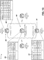
- provider edge device PE1 may store a table that includes IP addresses of 1.2.3.4 (e.g., PE IP Address) associated with VLAN identifiers 10, 11, 12, and 13 (e.g., VLAN ID).
- the table for provider edge device PE1 also shows that the VLAN identifiers are associated with ESIs ESI, ES2, ES3, and ES4.
- the table for provider edge device PE1 further shows that the IP addresses, VLAN identifiers, and ESIs are associated with an interface status of UP, indicating that provider edge device PE1 may use an associated interface to communicate.
- provider edge device PE1 may be configured with an ESI per subinterface, as indicated by each VLAN identifier being associated with a different ESI.
- provider edge device PE2 may store a table that includes IP addresses of 2.3.4.5 associated with VLAN identifiers 13, 14, 15, and 16.
- the table for provider edge device PE2 also shows that each of the VLAN identifiers are associated with an ESI (e.g., ES1, ES2, ES3, and ES4).
- the table for provider edge device PE2 also shows that the IP addresses, VLAN identifiers, and ESIs are associated with an interface status of UP.
- provider edge device PE2 may be configured with an ESI per subinterface, as indicated by each VLAN identifier being associated with a different ESI.
- provider edge devices PE1 and PE2 may be configured with different ranges of VLAN identifiers (e.g., a range of 10 to 13 for PE1 and a range of 13 to 16 for PE2).
- ranges of VLAN identifiers associated with each of provider edge devices PE1 and PE2 have different minimum VLAN identifiers (e.g., a minimum VLAN identifier of 10 for PE1 and a minimum VLAN identifier of 13 for PE2).
- provider edge devices PE1 and PE2 may exchange Ethernet virtual private network (EVPN) routes that include information identifying a type of the EVPN route (e.g., Type), a VLAN identifier range (e.g., VLAN ID Range), and/or a route of the provider edge device (e.g., Route).
- the EVPN route from provider edge device PE1 may include information identifying the type of the route as a type 4 route, the VLAN identifier range as 10 to 13, and the route as IP address 1.2.3.4.
- the EVPN route from PE2 may include information identifying the type of the route as a type 4 route, the VLAN identifier range as 13 to 16, and the route as IP address 2.3.4.5.
- provider edge devices PE1 and PE2 may store tables of information about the provider edge devices PE1 and PE2 (e.g., based on exchanging EVPN routes). For example, the tables may be ordered by IP address (e.g., lowest to highest, highest to lowest, etc.). In addition, the tables may include a provider edge device number (e.g., PE number) for provider edge devices PE1 and PE2, a provider edge device identifier (e.g., PE Device) identifying provider edge devices PE1 and PE2, and an IP address associated with provider edge devices PE1 and PE2 (e.g., PE IP address).
- PE edge device number e.g., PE number
- provider edge device identifier e.g., PE Device
- provider edge devices PE1 and PE2 may identify a minimum common VLAN identifier between provider edge devices PE1 and PE2 by comparing the ranges of VLAN identifiers of provider edge devices PE1 and PE2 and may select (e.g., elect) a provider edge device as a designated forwarder. For example, provider edge devices PE1 and PE2 may identify VLAN identifier 13 as the minimum common VLAN identifier between provider edge devices PE1 and PE2 and may select provider edge device PE2 as the designated forwarder using the algorithm V mod N.
- provider edge devices PE1 and PE2 may use VLAN identifier 13 as V, based on 13 being the minimum common VLAN identifier, and 2 as N , based on there being two provider edge devices in the multihomed environment.
- 13 mod 2 equals 1, which provider edge devices PE1 and PE2 may correspond to PE number 1.
- provider edge devices PE1 and PE2 may select PE2 as the designated forwarder.
- provider edge device PE1 may forward BUM traffic, received from customer edge device CE2, to provider edge device PE2 (e.g., based on provider edge device PE2 having been selected as the designated forwarder). As shown by reference number 140, provider edge device PE2 may forward BUM traffic, received from provider edge device PE1 and customer edge device CE2, to customer edge device CE1.
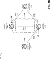
- provider edge device PE3 may be added to the network.
- provider edge device PE3 may store a table having an IP address of 3.4.5.6 associated with VLAN identifiers 12, 13, and 14.
- the table for provider edge device PE3 may further include VLAN identifiers associated with the same ESI (e.g., ES4), thereby indicating that provider edge device PE3 is configured with an ESI per physical device.
- the table for provider edge device PE3 may further include the IP address, the VLAN identifiers, and the ESIs associated with an interface status of UP.
- provider edge devices PE1, PE2, and PE3 may exchange EVPN routes that include a configuration identifier that identifies the ESI configuration as an ESI per physical device or an ESI per subinterface.
- provider edge devices PE1, PE2, and PE3 may each identify an ESI configuration of provider edge devices PE1, PE2, and PE3 using the configuration identifier included in the EVPN routes.
- provider edge device PE1 may transmit an EVPN route for provider edge device PE1 to provider edge device PE3 and may receive EVPN routes for provider edge devices PE2 and PE3 from provider edge device PE3.
- provider edge device PE2 may receive EVPN routes for provider edge devices PE1 and PE3 from provider edge device PE3 and may transmit an EVPN route for provider edge device PE2 to provider edge device PE3.
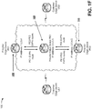
- provider edge devices PE1, PE2, and PE3 may modify a status of subinterfaces based on the ESI configurations of provider edge devices PE1, PE2, and PE3. For example, provider edge devices PE1, PE2, and PE3 may use interfaces with the same ESI to communicate with each other.
- the interface statuses for the VLAN identifiers have been set to DOWN, with the exception of the interface status associated with VLAN identifier 13, which is common to provider edge devices PE1, PE2, and PE3, and which has the same ESI (e.g., ES4) configured across provider edge device devices PE1, PE2, and PE3.
- provider edge devices PE1 and PE2 may select provider edge device PE2 as the designated forwarder based on the VLAN identifier associated with the common ESI (e.g., may use VLAN identifier 13, associated with ESI ES4, as V in the algorithm V mod N ).
- provider edge devices PE1 and PE2 may not consider PE3 for purposes of determining N in the algorithm V mod N, based on PE3 having a different ESI configuration from provider edge devices PE1 and PE2. For example, PE1 and PE2 may use 2 as N , rather than 3, based on PE3 having a different ESI configuration from provider edge devices PE1 and PE2.
- provider edge devices PE1 and PE2 may prevent provider edge device PE3 from selecting a designated forwarder (e.g., by transmitting a message to provider edge device PE3), based on provider edge device PE3 having a different ESI configuration from provider edge devices PE1 and PE2.
- provider edge devices PE1 and PE2 may determine a result of 13 mod 2 , compare the result to PE numbers included in the tables shown by reference numbers 120 and 125 described above, and select the corresponding provider edge device as the designated forwarder when the comparison indicates a match. For example, provider edge devices PE1 and PE2 may determine that the result of the algorithm 13 mod 2 is 1, may identify a PE number in the tables shown by reference numbers 120 and 125 that matches the result of the algorithm (e.g., may identify PE number 1 as matching the result of 1), determine that PE number 1 corresponds to provider edge device PE2, and select PE2 as the designated forwarder.
- a result of 0 may cause provider edge devices PE1 and PE2 to select provider edge device PE1 as the designated forwarder (e.g., based on 0 matching PE number 0, which corresponds to provider edge device PE1).
- Provider edge devices PE1 and PE2 may provide information identifying the designated forwarder to provider edge device PE3, thereby enabling provider edge devices PE1, PE2, and PE3 to communicate with the same designated forwarder.
- provider edge devices PE1, PE2 and PE3 may receive BUM traffic from customer edge device CE2. As further shown in Fig. 1H , provider edge devices PE1 and PE3 may forward the BUM traffic to provider edge device PE2, based on PE2 having been selected as the designated forwarder. As shown by reference number 170, provider edge device PE2, as the designated forwarder, may forward the BUM traffic to customer edge device CE1. In this way, a layer 2 loop may be prevented.
- FIGs. 1A-1H are provided merely as an example. Other examples are possible and may differ from what was described with regard to Figs. 1A-1H .
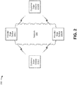
- Fig. 2 is a diagram of an example environment 200 in which systems and/or methods, described herein, may be implemented.
- environment 200 may include one or more customer edge devices 210-1 through 210-M (M ⁇ 1) (hereinafter referred to collectively as “customer edge devices 210," and individually as “customer edge device 210"), one or more provider edge devices 220-1 through 220-N (N ⁇ 1) (hereinafter referred to collectively as “provider edge devices 220,” and individually as “provider edge device 220”), and a network 230.
- Devices of environment 200 may interconnect via wired connections, wireless connections, or a combination of wired and wireless connections.
- Customer edge device 210 includes one or more devices (e.g., one or more traffic transfer devices) capable of processing and/or transferring traffic.
- customer edge device 210 may include a firewall, a router, a gateway, a switch, a hub, a bridge, a reverse proxy, a server (e.g., a proxy server), a security device, an intrusion detection device, a load balancer, or a similar type of device.
- customer edge device 210 may transmit traffic to provider edge device 220, as described elsewhere herein. Additionally, or alternatively, customer edge device 210 may receive traffic from provider edge device 220, as described elsewhere herein.
- Provider edge device 220 includes one or more devices (e.g., one or more traffic transfer devices) capable of processing and/or transferring traffic between endpoint devices.
- provider edge device 220 may include a firewall, a router, a gateway, a switch, a hub, a bridge, a reverse proxy, a server (e.g., a proxy server), a security device, an intrusion detection device, a load balancer, or a similar type of device.
- provider edge device 220 may receive traffic from customer edge device 210 and may provide the traffic to another customer edge device 210, as described elsewhere herein.
- provider edge device 220 may receive traffic from customer edge device 210 and may provide the traffic to another provider edge device 220, as described elsewhere herein.
- provider edge device 220 may be associated with network 230, may have a particular configuration (e.g., an ESI configuration), and/or may store a set of EVPN routes, as described elsewhere herein.
- Network 230 includes one or more wired and/or wireless networks.
- network 230 may include a multiprotocol label switching (MPLS) network, a cellular network (e.g., a long-term evolution (LTE) network, a 3G network, or a code division multiple access (CDMA) network), a public land mobile network (PLMN), a local area network (LAN), a wide area network (WAN), a metropolitan area network (MAN), a telephone network (e.g., the Public Switched Telephone Network (PSTN)), an EVPN network, a private network, an ad hoc network, an intranet, the Internet, a fiber optic-based network, a cloud computing network, or the like, and/or a combination of these or other types of networks.
- MPLS multiprotocol label switching
- LTE long-term evolution
- CDMA code division multiple access
- PLMN public land mobile network
- LAN local area network
- WAN wide area network
- MAN metropolitan area network
- PSTN Public
- the number and arrangement of devices and networks shown in Fig. 2 are provided as an example. In practice, there may be additional devices and/or networks, fewer devices and/or networks, different devices and/or networks, or differently arranged devices and/or networks than those shown in Fig. 2 . Furthermore, two or more devices shown in Fig. 2 may be implemented within a single device, or a single device shown in Fig. 2 may be implemented as multiple, distributed devices. Additionally, or alternatively, a set of devices (e.g., one or more devices) of environment 200 may perform one or more functions described as being performed by another set of devices of environment 200.
- Fig. 3 is a diagram of example components of a device 300.
- Device 300 may correspond to customer edge device 210 and/or provider edge device 220.
- customer edge device 210 and/or provider edge device 220 may include one or more devices 300 and/or one or more components of device 300.
- device 300 may include one or more input components 305-1 through 305-B (B ⁇ 1) (hereinafter referred to collectively as “input components 305,” and individually as “input component 305"), a switching component 310, one or more output components 315-1 through 315-C (C ⁇ 1) (hereinafter referred to collectively as “output components 315,” and individually as “output component 315"), and a controller 320.
- Input component 305 may be points of attachment for physical links and may be points of entry for incoming traffic, such as packets. Input component 305 may process incoming traffic, such as by performing data link layer encapsulation or decapsulation. In some implementations, input component 305 may send and/or receive packets. In some implementations, input component 305 may include an input line card that includes one or more packet processing components (e.g., in the form of integrated circuits), such as one or more interface cards (IFCs), packet forwarding components, line card controller components, input ports, processors, memories, and/or input queues. In some implementations, device 300 may include one or more input components 305.
- packet processing components e.g., in the form of integrated circuits
- IFCs interface cards
- packet forwarding components line card controller components
- input ports e.g., processors, memories, and/or input queues.
- device 300 may include one or more input components 305.
- Switching component 310 may interconnect input components 305 with output components 315.
- switching component 310 may be implemented via one or more crossbars, via busses, and/or with shared memories.
- the shared memories may act as temporary buffers to store packets from input components 305 before the packets are eventually scheduled for delivery to output components 315.
- switching component 310 may enable input components 305, output components 315, and/or controller 320 to communicate.
- Output component 315 may store packets and may schedule packets for transmission on output physical links. Output component 315 may support data link layer encapsulation or decapsulation, and/or a variety of higher-level protocols. In some implementations, output component 315 may send packets and/or receive packets. In some implementations, output component 315 may include an output line card that includes one or more packet processing components (e.g., in the form of integrated circuits), such as one or more IFCs, packet forwarding components, line card controller components, output ports, processors, memories, and/or output queues. In some implementations, device 300 may include one or more output components 315. In some implementations, input component 305 and output component 315 may be implemented by the same set of components (e.g., an input/output component may be a combination of input component 305 and output component 315).
- Controller 320 is implemented in hardware, firmware, or a combination of hardware and software.
- Controller 320 includes a processor in the form of, for example, a central processing unit (CPU), a graphics processing unit (GPU), an accelerated processing unit (APU), a microprocessor, a microcontroller, a field-programmable gate array (FPGA), an application-specific integrated circuit (ASIC), and/or another type of processor that can interpret and/or execute instructions.
- controller 320 may include one or more processors that can be programmed to perform a function.
- controller 320 may include a random access memory (RAM), a read only memory (ROM), and/or another type of dynamic or static storage device (e.g., a flash memory, a magnetic memory, or an optical memory) that stores information and/or instructions for use by controller 320.
- RAM random access memory
- ROM read only memory
- static storage device e.g., a flash memory, a magnetic memory, or an optical memory
- controller 320 may communicate with other devices, networks, and/or systems connected to device 300 to exchange information regarding network topology. Controller 320 may create routing tables based on the network topology information, create forwarding tables based on the routing tables, and forward the forwarding tables to input components 305 and/or output components 315. Input components 305 and/or output components 315 may use the forwarding tables to perform route lookups for incoming and/or outgoing packets.
- Controller 320 may perform one or more processes described herein. Controller 320 may perform these processes in response to executing software instructions stored by a computer-readable medium.
- a computer-readable medium is may include a transient carrier medium or a non-transitory memory device.
- a memory device includes memory space within a single physical storage device or memory space spread across multiple physical storage devices.
- Software instructions may be read into a memory and/or storage component associated with controller 320 from another computer-readable medium or from another device via a communication interface. When executed, software instructions stored in a memory and/or storage component associated with controller 320 may cause controller 320 to perform one or more processes described herein. Additionally, or alternatively, hardwired circuitry may be used in place of or in combination with software instructions to perform one or more processes described herein. Thus, implementations described herein are not limited to any specific combination of hardware circuitry and software.
- device 300 may include additional components, fewer components, different components, or differently arranged components than those shown in Fig. 3 . Additionally, or alternatively, a set of components (e.g., one or more components) of device 300 may perform one or more functions described as being performed by another set of components of device 300.
- a set of components e.g., one or more components
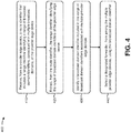
- Fig. 4 is a flow chart of an example process 400 for preventing data traffic loops associated with designated forwarder selection.
- one or more process blocks of Fig. 4 may be performed by provider edge device 220.
- one or more process blocks of Fig. 4 may be performed by another device or a group of devices separate from or including provider edge device 220, such as customer edge device 210.
- process 400 may include receiving, from a provider edge device, a route identifier that includes a range identifier identifying a range of broadcast domain identifiers, associated with multiple broadcast domains, of the provider edge device (block 410).
- provider edge device 220 when in an active-standby mode or an active-active mode, may receive, from another provider edge device 220, a route identifier that includes a range identifier identifying a range of broadcast domain identifiers, associated with multiple broadcast domains, of provider edge device 220.
- a route identifier may include an identifier that identifies (e.g., encodes) a route for a particular provider edge device 220.
- the route identifier may include network layer reachability information (NLRI) for provider edge device 220 or other information that identifies a route of provider edge device 220, such as an Ethernet virtual private network (EVPN) route.
- NLRI network layer reachability information
- EVPN Ethernet virtual private network
- the route identifier may include a route type identifier that identifies a type of the route.
- the route type identifier may identify the type of the route as a type 1 route identifier, a type 4 route identifier, or the like.
- a type 1 route may include an auto-discovery route per Ethernet segment, an auto-discovery route per EVPN instance (EVI), or the like.
- a type 4 route may include an Ethernet segment route.
- the route identifier may include a route distinguisher that identifies the provider edge device, such as an Internet Protocol (IP) address.
- IP Internet Protocol
- the route identifier may include an ESI that identifies a particular Ethernet segment.
- a range identifier may include an identifier that identifies a range of broadcast domain identifiers configured on provider edge device 220.
- a range identifier may include VLAN identifiers, such as a range of VLAN identifiers (e.g., VLAN identifiers 10 to 15, 12 to 20, 1 to 13, etc.).
- a broadcast domain may include a logical division of a computer network in which all nodes can reach each other at the data link layer, (e.g., layer 2).
- a broadcast domain may include a VLAN, a LAN, or the like.
- provider edge device 220 may receive the route identifier from another provider edge device 220. For example, provider edge device 220 may receive the route identifier upon request by provider edge device 220. As another example, provider edge device 220 may receive the route identifier when provider edge device 220 powers on, boots up, and/or according to a schedule (e.g., periodically). Additionally, or alternatively, provider edge device 220 may receive the route identifier when an additional provider edge device 220 is added to a multihomed environment (e.g., connected to network 230).
- a multihomed environment e.g., connected to network 230.
- provider edge device 220 may receive route identifiers from multiple provider edge devices 220. For example, provider edge device 220 may receive a first route identifier from a first provider edge device 220 and a second route identifier from a second provider edge device 220. Additionally, or alternatively, provider edge device 220 may provide a route identifier to one or more other provider edge devices 220. In this way, multiple provider edge devices 220 connected network 230 may exchange route identifiers so that each of the provider edge devices 220 receives a route identifier from all other provider edge devices 220 connected to network 230.
- a network administrator may further configure the route identifier to include an additional type-length-value (TLV) element, where the type may indicate a type of field with which the message is associated, the length may indicate a length (e.g., in bytes) of the value field, and the value may include data for the message with which the TLV element is associated.
- provider edge device 220 may use the TLV element to provide information associated with provider edge device 220.
- the TLV element to include a range identifier that identifies a range of broadcast domain identifiers configured on provider edge device 220. To illustrate, assume that provider edge device 220 is configured with VLAN identifiers 10 to 20.
- the range identifier may identify that the range of VLAN identifiers configured on provider edge device 220 includes VLAN identifiers 10 to 20. In this way, provider edge device 220 may use a TLV element to exchange information associated with broadcast domain identifiers configured on provider edge device 220.
- process 400 may include extracting, from the route identifier, the range identifier identifying the range of broadcast domain identifiers of the provider edge device (block 420).
- provider edge device 220 may extract, from the route identifier, the range identifier identifying the range of broadcast domain identifiers of provider edge device 220.
- provider edge device 220 may process the route identifier to extract the range identifier. In some implementations, when processing the route identifier, provider edge device 220 may parse the route identifier to extract the range identifier. Additionally, or alternatively, provider edge device 220 may extract the range identifier according to a set of rules, such as a set of rules that indicate a manner in which to process the route identifier to extract the range identifier, a set of rules that indicate an octet position of the range identifier in the route identifier, or the like. Additionally, or alternatively, provider edge device 220 may process the route identifier based on information identifying a format or a structure of the route identifier.
- provider edge device 220 may extract multiple range identifiers from multiple route identifiers. For example, provider edge device 220 may extract a first range identifier from a first route identifier for a first provider edge device 220 and may extract a second range identifier from a second route identifier for a second provider edge device 220. In this way, provider edge device 220 may identify a range of broadcast domain identifiers associated with one or more other provider edge devices 220.
- provider edge device 220 may store the range identifier based on, or in association with, extracting the range identifier.
- provider edge device 220 may store the range identifier in a data structure.
- the data structure may include a table stored by provider edge device 220.
- process 400 may include identifying a broadcast domain identifier included in the range of broadcast domain identifiers associated with multiple provider edge devices (block 430).
- provider edge device 220 may identify a broadcast domain identifier included in multiple ranges of broadcast domain identifiers, which are associated with multiple provider edge devices 220.
- provider edge device 220 may identify a domain identifier that is included in each of a first range of broadcast domain identifiers, associated with a first provider edge device 220, and a second range of broadcast domain identifiers, associated with a second provider edge device 220.
- provider edge device 220 may identify a broadcast domain identifier that is included in multiple range identifiers received from provider edge devices 220. For example, provider edge device 220 may identify a minimum broadcast domain identifier (e.g., with a minimum value relative to other broadcast domain identifiers) that is common to multiple provider edge devices 220 by using the range identifiers from the multiple provider edge devices 220 to identify the minimum value broadcast identifier that is included in the range identifiers from the multiple provider edge devices 220.
- a minimum broadcast domain identifier e.g., with a minimum value relative to other broadcast domain identifiers
- provider edge device 220 may identify a maximum broadcast domain identifier (e.g., with a maximum value relative to other broadcast domain identifiers) that is common to multiple provider edge devices 220 by using the range identifiers from the multiple provider edge devices 220 to identify a maximum value broadcast domain identifier that is included in the range identifiers from the multiple provider edge devices 220.
- a maximum broadcast domain identifier e.g., with a maximum value relative to other broadcast domain identifiers
- provider edge device 220 may compare a range identifier of provider edge device 220 and range identifiers of one or more other provider edge devices 220 to identify the broadcast domain identifier. For example, provider edge device 220 may compare a first range identifier that identifies a first VLAN identifier range of 10 to 15 for a first provider edge device 220 and a second range identifier that identifies a second VLAN identifier range of 12 to 20 for a second provider edge device 220.
- provider edge device 220 may identify VLAN identifier 12 as a minimum VLAN identifier that is common to the first provider edge device 220 and the second provider edge device 220 based on 12 being the minimum value VLAN identifier that is included in both the first VLAN identifier range and the second VLAN identifier range.
- provider edge device 220 may compare range identifiers of provider edge device 220 and one or more other provider edge devices 220 to identify a maximum broadcast domain identifier that is common to a first provider edge device 220 and a second provider edge device 220. For example, provider edge device 220 may compare a first range identifier that identifies a first VLAN identifier range of 10 to 15 for a first provider edge device 220 and a second range identifier that identifies a second VLAN identifier range of 12 to 20 for a second provider edge device 220.
- provider edge device 220 may identify VLAN identifier 15 as a maximum VLAN identifier that is common to the first provider edge device 220 and the second provider edge device 220 based on 15 being the maximum value VLAN identifier that is included in both the first VLAN identifier range and the second VLAN identifier range.
- a broadcast domain identifier may not be common among all provider edge devices 220 connected to network 230 (e.g., in a multihomed environment).
- provider edge device 220 may select a broadcast domain identifier according to a set of rules. For example, provider edge device 220 may select a broadcast domain identifier that is configured on a threshold quantity of provider edge devices 220 in the multihomed environment, a threshold percentage of provider edge devices 220 in the multihomed environment, or the like. Additionally, or alternatively, provider edge device 220 may provide, to other provider edge devices 220 that are not configured with the selected broadcast domain identifier, information that identifies the broadcast domain to use during designated forwarder selection (e.g., election). In this way, compatibility among provider edge devices 220 that have different configurations of broadcast domain identifiers may be enabled by enabling provider edge device 220 to obtain information about broadcast domain identifiers configured on other provider edge devices 220.
- process 400 may include selecting a designated forwarder, from among the multiple provider edge devices, using the broadcast domain identifier (block 440).
- provider edge device 220 may select (e.g., elect) a designated forwarder, from among the multiple provider edge devices 220, using a minimum broadcast domain identifier.
- provider edge device 220 may select a designated forwarder, from among the multiple provider edge devices 220, using a maximum broadcast identifier.
- provider edge device 220 may select a designated forwarder from among multiple provider edge devices 220 in a multihomed environment using an algorithm, such as a V mod N type of algorithm, where V is a broadcast domain identifier, and N is a quantity of provider edge devices 220 in the multihomed environment. For example, provider edge device 220 may select a designated forwarder using the broadcast domain identifier that is common to, or configured across, multiple provider edge devices 220 (e.g., as V in the algorithm V mod N ).
- provider edge device 220 may reduce or eliminate errors associated with selecting a designated forwarder that can occur when provider edge devices 220 in a multihomed environment are configured with different ranges of broadcast domain identifiers by using a broadcast domain identifier that is common among multiple provider edge devices 220.
- process 400 may include additional blocks, fewer blocks, different blocks, or differently arranged blocks than those depicted in Fig. 4 . Additionally, or alternatively, two or more of the blocks of process 400 may be performed in parallel.
- Fig. 5 is a flow chart of an example process 500 for preventing data traffic loops associated with designated forwarder selection.
- one or more process blocks of Fig. 5 may be performed by provider edge device 220.
- one or more process blocks of Fig. 5 may be performed by another device or a group of devices separate from or including provider edge device 220, such as customer edge device 210.
- process 500 may include receiving, from a provider edge device, information that identifies an Ethernet segment identifier (ESI) configuration of the provider edge device (block 510).
- provider edge device 220 in an active-active mode or an active-standby mode, may receive, from another provider edge device 220, a route identifier that includes a configuration identifier that identifies an ESI configuration of the other provider edge device 220.
- an ESI configuration may include an ESI configured per physical device.
- each provider edge device 220 may be configured with a single ESI, such that all subinterfaces (e.g., VLANs) of provider edge device 220 are associated with the same ESI.
- an ESI configuration may include an ESI configured per subinterface.
- each subinterface of provider edge device 220 may be configured with a different ESI, such that each subinterface of provider edge device 220 is associated with a different ESI.
- an ESI may identify an Ethernet segment (e.g., a set of links) between customer edge device 210 and one or more provider edge devices 220.
- an ESI may include a unique non-zero identifier that identifies an Ethernet segment.
- provider edge device 220 may receive a route identifier that includes a configuration identifier that identifies an ESI configuration of provider edge device 220.
- provider edge device 220 may receive a configuration identifier from another provider edge device 220.
- provider edge device 220 may receive the configuration identifier from the other provider edge device 220 upon request by provider edge device 220, when provider edge device 220 powers on or boots up, and/or according to a schedule (e.g., periodically).
- provider edge device 220 may receive the configuration identifier when an additional provider edge device 220 is added to a multihomed environment (e.g., connected to network 230).
- provider edge device 220 may receive a configuration identifier from multiple provider edge devices 220. For example, provider edge device 220 may receive a first configuration identifier from a first provider edge device 220 and a second configuration identifier from a second provider edge device 220. Additionally, or alternatively, provider edge device 220 may provide a configuration identifier to other provider edge devices 220.
- a network administrator may configure a route identifier to include a TLV element.
- provider edge device 220 may use the TLV element to store a configuration identifier.
- a configuration identifier of 00, included in the TLV element may identify an ESI configuration of provider edge device 220 as an ESI per physical device.
- a configuration identifier of 11, included in the TLV element may identify an ESI configuration of provider edge device 220 as an ESI configured per subinterface.
- provider edge devices 220 may use a route identifier that includes a TLV element, to exchange configuration identifiers.
- process 500 may include identifying the ESI configuration of the provider edge device using the configuration identifier included in the route identifier (block 520).
- provider edge device 220 may identify the ESI configuration of another provider edge device 220 using the configuration identifier included in the route identifier received from the other provider edge device 220.
- provider edge device 220 may identify the ESI configuration based on, or in association with, receiving the route identifier.
- provider edge device 220 may parse the route identifier to identify the configuration identifier. For example, provider edge device 220 may parse the route identifier using a set of rules and/or information identifying a structure of the route identifier to identify the configuration identifier. In some implementations, provider edge device 220 may identify the ESI configuration of a particular provider edge device 220, associated with the route identifier, based on identifying the configuration identifier. For example, provider edge device 220 may identify the configuration of another provider edge device 220 as an ESI per physical device based on identifying a configuration identifier of 00 in a TLV element included the route identifier. As another example, provider edge device 220 may identify the configuration of another provider edge device 220 as an ESI per subinterface based on identifying a configuration identifier of in a TLV element included in the route identifier.
- provider edge device 220 may identify the ESI configuration of another provider edge device 220 using a data structure. For example, provider edge device 220 may compare the configuration identifier to a set of configuration identifiers and corresponding ESI configurations to identify the ESI configuration of the other provider edge device 220. In some implementations, provider edge device 220 may identify the ESI configuration when the comparison indicates a match.
- provider edge device 220 may identify an ESI configuration of a particular provider edge device 220 based on whether a configuration identifier is included in a route identifier from the other provider edge device 220. For example, when a configuration identifier is included in a route identifier, provider edge device 220 may identify a first ESI configuration. As another example, when a configuration identifier is not included in a route identifier, provider edge device 220 may identify a second ESI configuration.
- provider edge device 220 may use information included in a route identifier to identify an ESI configuration of another provider edge device 220.
- process 500 may include configuring a status of a subinterface based on the ESI configuration of the provider edge device (block 530).
- provider edge device 220 may configure a status of a subinterface of provider edge device 220 based on the ESI configuration of provider edge device 220.
- provider edge device 220 may configure a status of a subinterface based on identifying the ESI configuration.
- provider edge device 220 may automatically configure the status of a broadcast domain in association with identifying the ESI configuration of the provider edge device 220. For example, when configuring a status of a subinterface, provider edge device 220 may automatically configure a status of a VLAN as up or down, active or inactive, or the like, based on the ESI configuration of provider edge device 220 and/or another provider edge device 220.
- a first provider edge device 220 is configured with an ESI per subinterface and the first provider edge device 220 exchanges route identifiers with a second provider edge device 220 configured with an ESI per physical device.
- the first and second provider edge devices 220 may identify a common ESI between the first and the second provider edge devices 220 using information included in the route identifier.
- the first and second provider edge devices 220 may set a status of a broadcast domain associated with the common ESI to up, active, or the like, to transmit traffic, such as BUM traffic, using the broadcast domain associated with the common ESI.
- the first and second provider edge devices 220 may set a status of the broadcast domain to permit the first and second provider edge devices 220 to transmit and/or receive IP traffic, BUM traffic, etc.
- the first and the second provider edge devices 220 may set a status of other broadcast domains, such as broadcast domains that are not associated with the common ESI, to down, inactive, or the like, to prevent transmission of traffic via the broadcast domains not associated with the common ESI.
- layer 2 loops that may occur due to a mismatch of ESI configurations between two communicating provider edge devices 220 may be prevented by using broadcast domains that are associated with ESIs that are common to (e.g., configured on) the communicating provider edge devices 220.
- process 500 may include selecting a designated forwarder from among multiple provider edge devices using a broadcast domain identifier associated with the multiple provider edge devices (block 540).
- provider edge device 220 may select (e.g., elect) a designated forwarder from among multiple provider edge devices 220 using a broadcast domain identifier that is a minimum broadcast domain identifier or a maximum broadcast domain identifier of the multiple provider edge devices 220.
- provider edge device 220 may select the designated forwarder based on, or in association with, configuring a status of a subinterface.
- provider edge device 220 may select a designated forwarder from among provider edge devices 220 in a multihomed environment using an algorithm, such as V mod N, where V is a broadcast domain identifier and N is a quantity of provider edge devices 220 in the multihomed environment.
- V is a broadcast domain identifier
- N is a quantity of provider edge devices 220 in the multihomed environment.
- provider edge devices 220 that are configured with a particular ESI configuration may not be included in a quantity of provider edge devices 220 used in the algorithm V mod N (e.g., used as N ).
- provider edge devices 220 that are configured with an ESI per physical device may be excluded from the quantity of devices used as N in the algorithm V mod N.
- provider edge devices 220 that are configured with an ESI per subinterface may be excluded from the quantity of devices used as N in the algorithm V mod N.
- provider edge devices 220 that are configured with a particular ESI configuration may be prevented from selecting a designated forwarder.
- a first provider edge device 220 configured with an ESI per subinterface may prevent a second provider edge device 220 configured with an ESI per physical device from using the algorithm to select a designated forwarder (e.g., by transmitting a message or a command to the second provider edge device 220).
- a first provider edge device 220 configured with an ESI per physical device may prevent a second provider edge device 220 configured with an ESI per subinterface from using the algorithm to select a designated forwarder (e.g., by transmitting a message or a command to the second provider edge device 220). This conserves processing resources of provider edge devices 220 that are configured with the particular ESI configuration by preventing provider edge devices 220 from participating in designated forwarder selection.
- provider edge devices 220 that are prevented from selecting a designated forwarder may receive, from another provider edge device 220 (e.g., a provider edge device 220 that has participated in designated forwarder selection), information that identifies the selected designated forwarder. In this way, errors that may occur from selecting a designated forwarder from provider edge devices 220 that have different ESI configurations may be reduced or eliminated by excluding provider edge devices 220 with a particular ESI configuration from designated forwarder selection.
- another provider edge device 220 e.g., a provider edge device 220 that has participated in designated forwarder selection
- a provider edge device 220 that is not configured to exchange broadcast domain identifiers and/or configuration identifiers may be added to, or operating within, a multihomed environment (e.g., network 230).
- a first provider edge device 220 may receive a route identifier from a second provider edge device 220 that does not include a TLV element that includes a broadcast domain identifier and/or a configuration identifier (e.g., based on the second provider edge device 220 not being configured to use a TLV element to exchange broadcast domain identifiers and/or configuration identifiers).
- provider edge device 220 may identify an ESI included in the route identifier by parsing the route identifier, such as by using a set of rules, information that identifies a structure of the route identifier, or the like. In some implementations, provider edge device 220 may compare an ESI extracted from the route identifier and ESIs configured on provider edge device 220 to identify a common ESI (e.g., common to provider edge device 220 and another provider edge device 220 that transmitted the route identifier).
- a common ESI e.g., common to provider edge device 220 and another provider edge device 220 that transmitted the route identifier.
- provider edge device 220 may set a status of a broadcast domain and/or a subinterface based on the comparison indicating a match. For example, provider edge device 220 may set a status of a broadcast domain associated with the same ESI included in the received route identifier to up, active, or the like. Additionally, or alternatively, provider edge device 220 may set a status of other broadcast domains associated with different ESIs than the ESI included in the received route identifier to down, inactive, or the like. In some implementations, provider edge device 220 may communicate using a broadcast domain with a status of up, active, or the like. This reduces or eliminates communication errors, such as layer 2 loops, that may occur when provider edge devices 220 that are not configured to exchange route identifiers and/or configuration identifiers using a route identifier.
- provider edge device 220 may provide a message, such as a syslog message or an alert, to another device (e.g., for display). For example, provider edge device 220 may provide a message that indicates that a particular provider edge device 220 not configured to exchange broadcast domain identifiers and/or configuration identifiers, such as by using a TLV element included in a route identifier, has been connected to, or is operating within, network 230.
- provider edge device 220 configured to exchange route identifiers with a TLV element that includes a broadcast domain identifier and/or a configuration identifier, may be compatible with (e.g., can communicate with) another provider edge device 220, not configured to transmit a route identifier with a TLV, by adaptively configuring a status of subinterfaces of provider edge device 220. Additionally, communications between a first provider edge device 220, configured with an ESI per subinterface, and a second provider edge device 220, configured with an ESI per physical device, may be improved by reducing or eliminating layer 2 loops, or other communication errors, that may occur as a result of a mismatch in ESI configurations.
- process 500 may include additional blocks, fewer blocks, different blocks, or differently arranged blocks than those depicted in Fig. 5 . Additionally, or alternatively, two or more of the blocks of process 500 may be performed in parallel.
- Implementations described herein enable a provider edge device to exchange route identifiers that include information identifying a broadcast domain and/or an ESI configuration (e.g., using a TLV element included in the route identifier). Having a provider edge device exchange route identifiers that include information identifying a broadcast domain and/or an ESI configuration may enable provider edge devices configured with different broadcast domain identifiers and/or ESI configurations to select a designated forwarder using the same information, thereby reducing or eliminating layer 2 loops that may occur during designated forwarder selection.
- implementations described herein enable a provider edge device that is configured to transmit a route identifier that includes information identifying a broadcast domain and/or an ESI configuration to be compatible with another provider edge device that is not configured to transmit a route identifier that includes the information identifying a broadcast domain and/or an ESI configuration by adaptively configuring a status of subinterfaces of the provider edge device. This improves communication between the provider edge device and the other provider edge device by reducing or eliminating errors due to different configurations associated with using a route identifier to exchange information identifying a broadcast domain and/or an ESI configuration.
- a device may receive a route identifier that includes a range identifier or a configuration identifier.
- the range identifier may identify a range of broadcast domain identifiers associated with a first device.
- the configuration identifier may identify an Ethernet segment identifier (ESI) configuration of the first device.
- ESE Ethernet segment identifier
- the device may identify the range identifier or the configuration identifier included in the route identifier.
- the device may select a designated forwarder from among multiple devices based on the range of broadcast domain identifiers or based on identifying the configuration identifier.
- the designated forwarder may be the same designated forwarder selected by at least one other device.
- the term component is intended to be broadly construed as hardware, firmware, and/or a combination of hardware and software.
- satisfying a threshold may refer to a value being greater than the threshold, more than the threshold, higher than the threshold, greater than or equal to the threshold, less than the threshold, fewer than the threshold, lower than the threshold, less than or equal to the threshold, equal to the threshold, etc.
Landscapes
- Engineering & Computer Science (AREA)
- Computer Networks & Wireless Communication (AREA)
- Signal Processing (AREA)
- Computer Security & Cryptography (AREA)
- Data Exchanges In Wide-Area Networks (AREA)
Description
- Multihoming can be useful for connecting a host or network to multiple networks in order to increase reliability, to improve performance, and/or to decrease cost. Multihoming is the practice of connecting a host or a network to more than one network. For example, a mobile phone may be connected to a Wi-Fi network and a third generation (3G) network simultaneously. Multihoming may increase reliability by providing multiple links for packets (e.g., Internet Protocol (IP) packets), so that if a link fails, the packets can be routed through other links. A multihomed host may be assigned multiple addresses (e.g., IP addresses), one per connected network.
- "BGP MPLS Based Ethernet VPN; draft-raggarwa-sajassi-12vpn-evpn-04.txt" by Aggarwal et al. for the Internet Engineering Task Force describes procedures for BGP MPLS-based Ethernet VPNs (EVPN). It does not disclose preventing a device from selecting a designated forwarder.
- "A new designated forwarder election for the EVPN; draft-ietf-bess-evpn-df-election-00.txt" by Mohanty et al. for the Internet Engineering Task Force describes an improved EVPN Designated Forwarder Election algorithm. It does not disclose preventing a device from selecting a designated forwarder.
- "RFC 7432 - BGP MPLS-Based Ethernet VPN" by Sajassi et al. for the Internet Engineering Task Force describes procedures for BGP MPLS-based Ethernet VPNs (EVPN). It does not disclose preventing a device from selecting a designated forwarder.
- The invention is defined by the appended claims. According to some possible implementations, a device may receive a route identifier that includes a range identifier or a configuration identifier. The range identifier may identify a range of broadcast domain identifiers associated with a first device. The configuration identifier may identify an Ethernet segment identifier (ESI) configuration of the first device. The device may identify the range identifier or the configuration identifier included in the route identifier. The device may select a designated forwarder from among multiple devices based on the range of broadcast domain identifiers or based on identifying the configuration identifier. The designated forwarder may be the same designated forwarder selected by at least one other device.
- According to some possible implementations, a computer-readable medium may store one or more instructions that, when executed by one or more processors, cause the one or more processors to receive, from multiple provider edge devices, multiple route identifiers that include multiple range identifiers or multiple configuration identifiers. The multiple range identifiers or the multiple configuration identifiers may be included in a type-length-value (TLV) element of the multiple route identifiers. A first range identifier included in a first route identifier of the multiple route identifiers may be different than a second range identifier included in a second route identifier of the multiple route identifiers. A first configuration identifier included in the first route identifier may be different than a second configuration identifier included in the second route identifier. The one or more instructions may cause the one or more processors to extract the multiple range identifiers or the multiple configuration identifiers from the TLV element of the multiple route identifiers. The one or more instructions may cause the one or more processors to identify the multiple range identifiers or the multiple configuration identifiers based on extracting the multiple range identifiers or the multiple configuration identifiers. The one or more instructions may cause the one or more processors to elect a designated forwarder from among the multiple provider edge devices using an algorithm. The algorithm may be the same algorithm used by the multiple provider edge devices to elect the same designated forwarder.
- According to some possible implementations, a method may include receiving, by a device, one or more route identifiers from one or more other devices. The one or more route identifiers may include one or more range identifiers associated with one or more ranges of broadcast domain identifiers configured on the one or more other devices, or one or more configuration identifiers associated with one or more ESI configurations of the one or more other devices. The method may include identifying, by the device, the one or more range identifiers or the one or more configuration identifiers included in the one or more route identifiers. The one or more range identifiers may include at least one range identifier that is different than a range identifier configured on another device. The one or more configuration identifiers may include at least one configuration identifier that is different than a configuration identifier configured on another device. The method may include selecting, by the device, a designated forwarder from among the device and the one or more other devices.
-
-
Figs. 1A-1H are diagrams of an overview of an example implementation described herein; -
Fig. 2 is a diagram of an example environment in which systems and/or methods, described herein, may be implemented; -
Fig. 3 is a diagram of example components of one or more devices ofFig. 2 ; -
Fig. 4 is a flow chart of an example process for preventing data traffic loops associated with designated forwarder selection; and -
Fig. 5 is a flow chart of another example process for preventing data traffic loops associated with designated forwarder selection. - The following detailed description of example implementations refers to the accompanying drawings. The same reference numbers in different drawings may identify the same or similar elements.
- Multiple provider edge devices in a multihomed network may be configured to select (e.g., elect) one of the provider edge devices as a designated forwarder to forward network traffic to a customer edge device. As such, multihoming may provide redundant connectivity so that connectivity is provided even where a failure in the multihomed network is detected.
- During designated forwarder selection, provider edge devices may use an algorithm, V mod N, to select the designated forwarder, where V is the lowest value virtual local area network (VLAN) identifier configured on a provider edge device and N is a quantity of provider edge devices that are multihomed to a particular Ethernet segment (e.g., a set of Ethernet links that connects two or more provider edge devices when a customer edge device is multihomed to the provider edge devices).
- In some cases, multiple provider edge devices may have different configurations, such as due to a configuration error by a network administrator, due to one or more provider edge devices being a legacy provider edge device, or the like. For example, the different configurations may include different VLAN identifiers (e.g., associated with active VLANs). Application of the V mod N algorithm when provider edge devices have different VLAN identifiers may cause errors during the selection of a designated forwarder. For example, the different configurations may cause provider edge devices to select different designated forwarders. Selection of different designated forwarders may cause a layer 2 loop between the selected designated forwarders. For example, a layer 2 loop may occur when multiple provider edge devices in a multihomed environment are selected as designated forwarders, causing the designated forwarders to repeatedly exchange broadcast traffic, unknown unicast traffic, and multicast traffic (BUM traffic) without forwarding the BUM traffic to a customer edge device.
- As an example, assume that a first provider edge device is configured with
VLAN identifiers 4 through 10 and a second provider edge device is configured with VLAN identifiers 5 through 10. Based on the different minimum VLAN identifiers on each of the provider edge devices, (e.g., the first provider edge device has a minimum VLAN identifier of 4 and the second provider edge device has a minimum VLAN identifier of 5) application of the V mod N algorithm by the first provider edge device may cause the first provider edge device to select the first provider edge device as the designated forwarder and application of the V mod N algorithm by the second provider edge device may cause the second provider edge device to select the second provider edge device as the designated forwarder. Because both the first provider edge device and the second provider edge device have been selected as a designated forwarder, the first and second provider edge devices may attempt to forward BUM traffic to each other, resulting in a layer 2 loop. - In addition, or in other cases, the provider edge devices may have different Ethernet segment identifier (ESI) configurations. For example, a first provider edge device may be configured with an ESI per physical device and a second provider edge device may be configured with an ESI per subinterface (or VLAN). A mismatch between the ESI configurations of the first provider edge device and the second provider edge device may cause multiple provider edge devices to be selected as designated forwarders. Based on the multiple provider edge devices being selected as designated forwarders, both provider edge devices may forward BUM traffic to each other (e.g., a layer 2 loop).
- In implementations described herein, provider edge devices may exchange route identifiers that include information identifying VLAN identifiers and ESI configurations. For example, when multihomed provider edge devices advertise
type 4 routes to other provider edge devices in a common multihomed environment, one or more type-length-value (TLV) elements may be included with thetype 4 route. The provider edge devices may use the TLV elements in thetype 4 route to exchange VLAN identifiers and/or configuration identifiers (e.g., that identify whether a provider edge device is configured with an ESI per subinterface or an ESI per physical device). Having provider edge devices exchange route identifiers that include VLAN identifiers and/or configuration identifiers may enable provider edge devices with different configurations to select a designated forwarder using the same information, thereby reducing or eliminating layer 2 loops that may occur during designated forwarder selection. -
Figs. 1A-1H are diagrams of an overview of anexample implementation 100 described herein. As shown inFig. 1A , provider edge device PE1 and provider edge device PE2 may operate within a network, and may exchange traffic among each other and among customer edge device CE1 and customer edge device CE2. The environment shown inexample implementation 100 may include a multihomed environment based on at least one customer edge device being connected to multiple provider edge devices. - As shown by
reference number 105, provider edge device PE1 may store a table that includes IP addresses of 1.2.3.4 (e.g., PE IP Address) associated withVLAN identifiers reference number 105, provider edge device PE1 may be configured with an ESI per subinterface, as indicated by each VLAN identifier being associated with a different ESI. - As shown by
reference number 110, provider edge device PE2 may store a table that includes IP addresses of 2.3.4.5 associated withVLAN identifiers reference number 110, provider edge device PE2 may be configured with an ESI per subinterface, as indicated by each VLAN identifier being associated with a different ESI. - As further shown in
Fig. 1A , and byreference numbers - As shown in
Fig. 1B , and byreference numbers 115, provider edge devices PE1 and PE2 may exchange Ethernet virtual private network (EVPN) routes that include information identifying a type of the EVPN route (e.g., Type), a VLAN identifier range (e.g., VLAN ID Range), and/or a route of the provider edge device (e.g., Route). The EVPN route from provider edge device PE1 may include information identifying the type of the route as atype 4 route, the VLAN identifier range as 10 to 13, and the route as IP address 1.2.3.4. The EVPN route from PE2 may include information identifying the type of the route as atype 4 route, the VLAN identifier range as 13 to 16, and the route as IP address 2.3.4.5. - As shown in
Fig. 1C , and byreference numbers - As shown by
reference number 130, provider edge devices PE1 and PE2 may identify a minimum common VLAN identifier between provider edge devices PE1 and PE2 by comparing the ranges of VLAN identifiers of provider edge devices PE1 and PE2 and may select (e.g., elect) a provider edge device as a designated forwarder. For example, provider edge devices PE1 and PE2 may identifyVLAN identifier 13 as the minimum common VLAN identifier between provider edge devices PE1 and PE2 and may select provider edge device PE2 as the designated forwarder using the algorithm V mod N. Continuing with the previous example, provider edge devices PE1 and PE2 may useVLAN identifier 13 as V, based on 13 being the minimum common VLAN identifier, and 2 as N, based on there being two provider edge devices in the multihomed environment. Continuing with the previous example, 13 mod 2 equals 1, which provider edge devices PE1 and PE2 may correspond toPE number 1. Based onPE number 1 being associated with provider edge device PE2, as shown byreference numbers - As shown in
Fig. 1D , and byreference number 135, provider edge device PE1 may forward BUM traffic, received from customer edge device CE2, to provider edge device PE2 (e.g., based on provider edge device PE2 having been selected as the designated forwarder). As shown byreference number 140, provider edge device PE2 may forward BUM traffic, received from provider edge device PE1 and customer edge device CE2, to customer edge device CE1. - As shown in Fig. IE, and by
reference number 145, provider edge device PE3 may be added to the network. As shown byreference number 150, provider edge device PE3 may store a table having an IP address of 3.4.5.6 associated withVLAN identifiers - As shown in
Fig. 1F , and byreference numbers 155, provider edge devices PE1, PE2, and PE3 may exchange EVPN routes that include a configuration identifier that identifies the ESI configuration as an ESI per physical device or an ESI per subinterface. In addition, provider edge devices PE1, PE2, and PE3 may each identify an ESI configuration of provider edge devices PE1, PE2, and PE3 using the configuration identifier included in the EVPN routes. For example, provider edge device PE1 may transmit an EVPN route for provider edge device PE1 to provider edge device PE3 and may receive EVPN routes for provider edge devices PE2 and PE3 from provider edge device PE3. As another example, provider edge device PE2 may receive EVPN routes for provider edge devices PE1 and PE3 from provider edge device PE3 and may transmit an EVPN route for provider edge device PE2 to provider edge device PE3. - As shown in
Fig. 1G , and byreference numbers 160, provider edge devices PE1, PE2, and PE3 may modify a status of subinterfaces based on the ESI configurations of provider edge devices PE1, PE2, and PE3. For example, provider edge devices PE1, PE2, and PE3 may use interfaces with the same ESI to communicate with each other. Continuing with the previous example, as shown byreference numbers VLAN identifier 13, which is common to provider edge devices PE1, PE2, and PE3, and which has the same ESI (e.g., ES4) configured across provider edge device devices PE1, PE2, and PE3. - As shown by
Fig. 1H , and byreference number 165, provider edge devices PE1 and PE2 may select provider edge device PE2 as the designated forwarder based on the VLAN identifier associated with the common ESI (e.g., may useVLAN identifier 13, associated with ESI ES4, as V in the algorithm V mod N). In addition, provider edge devices PE1 and PE2 may not consider PE3 for purposes of determining N in the algorithm V mod N, based on PE3 having a different ESI configuration from provider edge devices PE1 and PE2. For example, PE1 and PE2 may use 2 as N, rather than 3, based on PE3 having a different ESI configuration from provider edge devices PE1 and PE2. Further, provider edge devices PE1 and PE2 may prevent provider edge device PE3 from selecting a designated forwarder (e.g., by transmitting a message to provider edge device PE3), based on provider edge device PE3 having a different ESI configuration from provider edge devices PE1 and PE2. - To select a designated forwarder, provider edge devices PE1 and PE2 may determine a result of 13 mod 2, compare the result to PE numbers included in the tables shown by
reference numbers algorithm 13 mod 2 is 1, may identify a PE number in the tables shown byreference numbers PE number 1 as matching the result of 1), determine thatPE number 1 corresponds to provider edge device PE2, and select PE2 as the designated forwarder. - Conversely, and as another example, a result of 0 may cause provider edge devices PE1 and PE2 to select provider edge device PE1 as the designated forwarder (e.g., based on 0
matching PE number 0, which corresponds to provider edge device PE1). Provider edge devices PE1 and PE2 may provide information identifying the designated forwarder to provider edge device PE3, thereby enabling provider edge devices PE1, PE2, and PE3 to communicate with the same designated forwarder. - As further shown in
Fig. 1H , provider edge devices PE1, PE2 and PE3 may receive BUM traffic from customer edge device CE2. As further shown inFig. 1H , provider edge devices PE1 and PE3 may forward the BUM traffic to provider edge device PE2, based on PE2 having been selected as the designated forwarder. As shown byreference number 170, provider edge device PE2, as the designated forwarder, may forward the BUM traffic to customer edge device CE1. In this way, a layer 2 loop may be prevented. - As indicated above,
Figs. 1A-1H are provided merely as an example. Other examples are possible and may differ from what was described with regard toFigs. 1A-1H . -
Fig. 2 is a diagram of anexample environment 200 in which systems and/or methods, described herein, may be implemented. As shown inFig. 2 ,environment 200 may include one or more customer edge devices 210-1 through 210-M (M ≥ 1) (hereinafter referred to collectively as "customer edge devices 210," and individually as "customer edge device 210"), one or more provider edge devices 220-1 through 220-N (N ≥ 1) (hereinafter referred to collectively as "provider edge devices 220," and individually as "provider edge device 220"), and anetwork 230. Devices ofenvironment 200 may interconnect via wired connections, wireless connections, or a combination of wired and wireless connections. -
Customer edge device 210 includes one or more devices (e.g., one or more traffic transfer devices) capable of processing and/or transferring traffic. For example,customer edge device 210 may include a firewall, a router, a gateway, a switch, a hub, a bridge, a reverse proxy, a server (e.g., a proxy server), a security device, an intrusion detection device, a load balancer, or a similar type of device. In some implementations,customer edge device 210 may transmit traffic toprovider edge device 220, as described elsewhere herein. Additionally, or alternatively,customer edge device 210 may receive traffic fromprovider edge device 220, as described elsewhere herein. -
Provider edge device 220 includes one or more devices (e.g., one or more traffic transfer devices) capable of processing and/or transferring traffic between endpoint devices. For example,provider edge device 220 may include a firewall, a router, a gateway, a switch, a hub, a bridge, a reverse proxy, a server (e.g., a proxy server), a security device, an intrusion detection device, a load balancer, or a similar type of device. In some implementations,provider edge device 220 may receive traffic fromcustomer edge device 210 and may provide the traffic to anothercustomer edge device 210, as described elsewhere herein. Additionally, or alternatively,provider edge device 220 may receive traffic fromcustomer edge device 210 and may provide the traffic to anotherprovider edge device 220, as described elsewhere herein. In some implementations,provider edge device 220 may be associated withnetwork 230, may have a particular configuration (e.g., an ESI configuration), and/or may store a set of EVPN routes, as described elsewhere herein. -
Network 230 includes one or more wired and/or wireless networks. For example,network 230 may include a multiprotocol label switching (MPLS) network, a cellular network (e.g., a long-term evolution (LTE) network, a 3G network, or a code division multiple access (CDMA) network), a public land mobile network (PLMN), a local area network (LAN), a wide area network (WAN), a metropolitan area network (MAN), a telephone network (e.g., the Public Switched Telephone Network (PSTN)), an EVPN network, a private network, an ad hoc network, an intranet, the Internet, a fiber optic-based network, a cloud computing network, or the like, and/or a combination of these or other types of networks. - The number and arrangement of devices and networks shown in
Fig. 2 are provided as an example. In practice, there may be additional devices and/or networks, fewer devices and/or networks, different devices and/or networks, or differently arranged devices and/or networks than those shown inFig. 2 . Furthermore, two or more devices shown inFig. 2 may be implemented within a single device, or a single device shown inFig. 2 may be implemented as multiple, distributed devices. Additionally, or alternatively, a set of devices (e.g., one or more devices) ofenvironment 200 may perform one or more functions described as being performed by another set of devices ofenvironment 200. -
Fig. 3 is a diagram of example components of adevice 300.Device 300 may correspond tocustomer edge device 210 and/orprovider edge device 220. In some implementations,customer edge device 210 and/orprovider edge device 220 may include one ormore devices 300 and/or one or more components ofdevice 300. As shown inFig. 3 ,device 300 may include one or more input components 305-1 through 305-B (B ≥ 1) (hereinafter referred to collectively as "input components 305," and individually as "input component 305"), aswitching component 310, one or more output components 315-1 through 315-C (C ≥ 1) (hereinafter referred to collectively as "output components 315," and individually as "output component 315"), and acontroller 320. -
Input component 305 may be points of attachment for physical links and may be points of entry for incoming traffic, such as packets.Input component 305 may process incoming traffic, such as by performing data link layer encapsulation or decapsulation. In some implementations,input component 305 may send and/or receive packets. In some implementations,input component 305 may include an input line card that includes one or more packet processing components (e.g., in the form of integrated circuits), such as one or more interface cards (IFCs), packet forwarding components, line card controller components, input ports, processors, memories, and/or input queues. In some implementations,device 300 may include one ormore input components 305. -
Switching component 310 may interconnectinput components 305 withoutput components 315. In some implementations, switchingcomponent 310 may be implemented via one or more crossbars, via busses, and/or with shared memories. The shared memories may act as temporary buffers to store packets frominput components 305 before the packets are eventually scheduled for delivery tooutput components 315. In some implementations, switchingcomponent 310 may enableinput components 305,output components 315, and/orcontroller 320 to communicate. -
Output component 315 may store packets and may schedule packets for transmission on output physical links.Output component 315 may support data link layer encapsulation or decapsulation, and/or a variety of higher-level protocols. In some implementations,output component 315 may send packets and/or receive packets. In some implementations,output component 315 may include an output line card that includes one or more packet processing components (e.g., in the form of integrated circuits), such as one or more IFCs, packet forwarding components, line card controller components, output ports, processors, memories, and/or output queues. In some implementations,device 300 may include one ormore output components 315. In some implementations,input component 305 andoutput component 315 may be implemented by the same set of components (e.g., an input/output component may be a combination ofinput component 305 and output component 315). -
Controller 320 is implemented in hardware, firmware, or a combination of hardware and software.Controller 320 includes a processor in the form of, for example, a central processing unit (CPU), a graphics processing unit (GPU), an accelerated processing unit (APU), a microprocessor, a microcontroller, a field-programmable gate array (FPGA), an application-specific integrated circuit (ASIC), and/or another type of processor that can interpret and/or execute instructions. In some implementations,controller 320 may include one or more processors that can be programmed to perform a function. - In some implementations,
controller 320 may include a random access memory (RAM), a read only memory (ROM), and/or another type of dynamic or static storage device (e.g., a flash memory, a magnetic memory, or an optical memory) that stores information and/or instructions for use bycontroller 320. - In some implementations,
controller 320 may communicate with other devices, networks, and/or systems connected todevice 300 to exchange information regarding network topology.Controller 320 may create routing tables based on the network topology information, create forwarding tables based on the routing tables, and forward the forwarding tables to inputcomponents 305 and/oroutput components 315.Input components 305 and/oroutput components 315 may use the forwarding tables to perform route lookups for incoming and/or outgoing packets. -
Controller 320 may perform one or more processes described herein.Controller 320 may perform these processes in response to executing software instructions stored by a computer-readable medium. A computer-readable medium is may include a transient carrier medium or a non-transitory memory device. A memory device includes memory space within a single physical storage device or memory space spread across multiple physical storage devices. - Software instructions may be read into a memory and/or storage component associated with
controller 320 from another computer-readable medium or from another device via a communication interface. When executed, software instructions stored in a memory and/or storage component associated withcontroller 320 may causecontroller 320 to perform one or more processes described herein. Additionally, or alternatively, hardwired circuitry may be used in place of or in combination with software instructions to perform one or more processes described herein. Thus, implementations described herein are not limited to any specific combination of hardware circuitry and software. - The number and arrangement of components shown in
Fig. 3 are provided as an example. In practice,device 300 may include additional components, fewer components, different components, or differently arranged components than those shown inFig. 3 . Additionally, or alternatively, a set of components (e.g., one or more components) ofdevice 300 may perform one or more functions described as being performed by another set of components ofdevice 300. -
Fig. 4 is a flow chart of anexample process 400 for preventing data traffic loops associated with designated forwarder selection. In some implementations, one or more process blocks ofFig. 4 may be performed byprovider edge device 220. In some implementations, one or more process blocks ofFig. 4 may be performed by another device or a group of devices separate from or includingprovider edge device 220, such ascustomer edge device 210. - As shown in
Fig. 4 ,process 400 may include receiving, from a provider edge device, a route identifier that includes a range identifier identifying a range of broadcast domain identifiers, associated with multiple broadcast domains, of the provider edge device (block 410). For example,provider edge device 220, when in an active-standby mode or an active-active mode, may receive, from anotherprovider edge device 220, a route identifier that includes a range identifier identifying a range of broadcast domain identifiers, associated with multiple broadcast domains, ofprovider edge device 220. - In some implementations, a route identifier may include an identifier that identifies (e.g., encodes) a route for a particular
provider edge device 220. For example, the route identifier may include network layer reachability information (NLRI) forprovider edge device 220 or other information that identifies a route ofprovider edge device 220, such as an Ethernet virtual private network (EVPN) route. In some implementations, the route identifier may include a route type identifier that identifies a type of the route. For example, the route type identifier may identify the type of the route as atype 1 route identifier, atype 4 route identifier, or the like. In some implementations, atype 1 route may include an auto-discovery route per Ethernet segment, an auto-discovery route per EVPN instance (EVI), or the like. In some implementations, atype 4 route may include an Ethernet segment route. Additionally, or alternatively, the route identifier may include a route distinguisher that identifies the provider edge device, such as an Internet Protocol (IP) address. Additionally, or alternatively, the route identifier may include an ESI that identifies a particular Ethernet segment. - In some implementations, a range identifier may include an identifier that identifies a range of broadcast domain identifiers configured on
provider edge device 220. For example, a range identifier may include VLAN identifiers, such as a range of VLAN identifiers (e.g.,VLAN identifiers 10 to 15, 12 to 20, 1 to 13, etc.). In some implementations, a broadcast domain may include a logical division of a computer network in which all nodes can reach each other at the data link layer, (e.g., layer 2). For example, a broadcast domain may include a VLAN, a LAN, or the like. - In some implementations,
provider edge device 220 may receive the route identifier from anotherprovider edge device 220. For example,provider edge device 220 may receive the route identifier upon request byprovider edge device 220. As another example,provider edge device 220 may receive the route identifier whenprovider edge device 220 powers on, boots up, and/or according to a schedule (e.g., periodically). Additionally, or alternatively,provider edge device 220 may receive the route identifier when an additionalprovider edge device 220 is added to a multihomed environment (e.g., connected to network 230). - In some implementations,
provider edge device 220 may receive route identifiers from multipleprovider edge devices 220. For example,provider edge device 220 may receive a first route identifier from a firstprovider edge device 220 and a second route identifier from a secondprovider edge device 220. Additionally, or alternatively,provider edge device 220 may provide a route identifier to one or more otherprovider edge devices 220. In this way, multipleprovider edge devices 220 connectednetwork 230 may exchange route identifiers so that each of theprovider edge devices 220 receives a route identifier from all otherprovider edge devices 220 connected tonetwork 230. - In some implementations, a network administrator may further configure the route identifier to include an additional type-length-value (TLV) element, where the type may indicate a type of field with which the message is associated, the length may indicate a length (e.g., in bytes) of the value field, and the value may include data for the message with which the TLV element is associated. In some implementations,
provider edge device 220 may use the TLV element to provide information associated withprovider edge device 220. For example, the TLV element to include a range identifier that identifies a range of broadcast domain identifiers configured onprovider edge device 220. To illustrate, assume thatprovider edge device 220 is configured withVLAN identifiers 10 to 20. In this case, the range identifier may identify that the range of VLAN identifiers configured onprovider edge device 220 includesVLAN identifiers 10 to 20. In this way,provider edge device 220 may use a TLV element to exchange information associated with broadcast domain identifiers configured onprovider edge device 220. - As further shown in
Fig. 4 ,process 400 may include extracting, from the route identifier, the range identifier identifying the range of broadcast domain identifiers of the provider edge device (block 420). For example,provider edge device 220 may extract, from the route identifier, the range identifier identifying the range of broadcast domain identifiers ofprovider edge device 220. - In some implementations,
provider edge device 220 may process the route identifier to extract the range identifier. In some implementations, when processing the route identifier,provider edge device 220 may parse the route identifier to extract the range identifier. Additionally, or alternatively,provider edge device 220 may extract the range identifier according to a set of rules, such as a set of rules that indicate a manner in which to process the route identifier to extract the range identifier, a set of rules that indicate an octet position of the range identifier in the route identifier, or the like. Additionally, or alternatively,provider edge device 220 may process the route identifier based on information identifying a format or a structure of the route identifier. - In some implementations,
provider edge device 220 may extract multiple range identifiers from multiple route identifiers. For example,provider edge device 220 may extract a first range identifier from a first route identifier for a firstprovider edge device 220 and may extract a second range identifier from a second route identifier for a secondprovider edge device 220. In this way,provider edge device 220 may identify a range of broadcast domain identifiers associated with one or more otherprovider edge devices 220. - In some implementations,
provider edge device 220 may store the range identifier based on, or in association with, extracting the range identifier. For example,provider edge device 220 may store the range identifier in a data structure. In some implementations, the data structure may include a table stored byprovider edge device 220. - As further shown in
Fig. 4 ,process 400 may include identifying a broadcast domain identifier included in the range of broadcast domain identifiers associated with multiple provider edge devices (block 430). For example,provider edge device 220 may identify a broadcast domain identifier included in multiple ranges of broadcast domain identifiers, which are associated with multipleprovider edge devices 220. Continuing with the previous example,provider edge device 220 may identify a domain identifier that is included in each of a first range of broadcast domain identifiers, associated with a firstprovider edge device 220, and a second range of broadcast domain identifiers, associated with a secondprovider edge device 220. - In some implementations,
provider edge device 220 may identify a broadcast domain identifier that is included in multiple range identifiers received fromprovider edge devices 220. For example,provider edge device 220 may identify a minimum broadcast domain identifier (e.g., with a minimum value relative to other broadcast domain identifiers) that is common to multipleprovider edge devices 220 by using the range identifiers from the multipleprovider edge devices 220 to identify the minimum value broadcast identifier that is included in the range identifiers from the multipleprovider edge devices 220. Additionally, or alternatively,provider edge device 220 may identify a maximum broadcast domain identifier (e.g., with a maximum value relative to other broadcast domain identifiers) that is common to multipleprovider edge devices 220 by using the range identifiers from the multipleprovider edge devices 220 to identify a maximum value broadcast domain identifier that is included in the range identifiers from the multipleprovider edge devices 220. - In some implementations,
provider edge device 220 may compare a range identifier ofprovider edge device 220 and range identifiers of one or more otherprovider edge devices 220 to identify the broadcast domain identifier. For example,provider edge device 220 may compare a first range identifier that identifies a first VLAN identifier range of 10 to 15 for a firstprovider edge device 220 and a second range identifier that identifies a second VLAN identifier range of 12 to 20 for a secondprovider edge device 220. In such a case,provider edge device 220 may identifyVLAN identifier 12 as a minimum VLAN identifier that is common to the firstprovider edge device 220 and the secondprovider edge device 220 based on 12 being the minimum value VLAN identifier that is included in both the first VLAN identifier range and the second VLAN identifier range. - Additionally, or alternatively,
provider edge device 220 may compare range identifiers ofprovider edge device 220 and one or more otherprovider edge devices 220 to identify a maximum broadcast domain identifier that is common to a firstprovider edge device 220 and a secondprovider edge device 220. For example,provider edge device 220 may compare a first range identifier that identifies a first VLAN identifier range of 10 to 15 for a firstprovider edge device 220 and a second range identifier that identifies a second VLAN identifier range of 12 to 20 for a secondprovider edge device 220. In such a case,provider edge device 220 may identifyVLAN identifier 15 as a maximum VLAN identifier that is common to the firstprovider edge device 220 and the secondprovider edge device 220 based on 15 being the maximum value VLAN identifier that is included in both the first VLAN identifier range and the second VLAN identifier range. - In some cases, a broadcast domain identifier may not be common among all
provider edge devices 220 connected to network 230 (e.g., in a multihomed environment). In such cases, and in some implementations,provider edge device 220 may select a broadcast domain identifier according to a set of rules. For example,provider edge device 220 may select a broadcast domain identifier that is configured on a threshold quantity ofprovider edge devices 220 in the multihomed environment, a threshold percentage ofprovider edge devices 220 in the multihomed environment, or the like. Additionally, or alternatively,provider edge device 220 may provide, to otherprovider edge devices 220 that are not configured with the selected broadcast domain identifier, information that identifies the broadcast domain to use during designated forwarder selection (e.g., election). In this way, compatibility amongprovider edge devices 220 that have different configurations of broadcast domain identifiers may be enabled by enablingprovider edge device 220 to obtain information about broadcast domain identifiers configured on otherprovider edge devices 220. - As further shown in
Fig. 4 ,process 400 may include selecting a designated forwarder, from among the multiple provider edge devices, using the broadcast domain identifier (block 440). For example,provider edge device 220 may select (e.g., elect) a designated forwarder, from among the multipleprovider edge devices 220, using a minimum broadcast domain identifier. As another example,provider edge device 220 may select a designated forwarder, from among the multipleprovider edge devices 220, using a maximum broadcast identifier. - In some implementations,
provider edge device 220 may select a designated forwarder from among multipleprovider edge devices 220 in a multihomed environment using an algorithm, such as a V mod N type of algorithm, where V is a broadcast domain identifier, and N is a quantity ofprovider edge devices 220 in the multihomed environment. For example,provider edge device 220 may select a designated forwarder using the broadcast domain identifier that is common to, or configured across, multiple provider edge devices 220 (e.g., as V in the algorithm V mod N). In this way,provider edge device 220 may reduce or eliminate errors associated with selecting a designated forwarder that can occur whenprovider edge devices 220 in a multihomed environment are configured with different ranges of broadcast domain identifiers by using a broadcast domain identifier that is common among multipleprovider edge devices 220. - Although
Fig. 4 shows example blocks ofprocess 400, in some implementations,process 400 may include additional blocks, fewer blocks, different blocks, or differently arranged blocks than those depicted inFig. 4 . Additionally, or alternatively, two or more of the blocks ofprocess 400 may be performed in parallel. -
Fig. 5 is a flow chart of anexample process 500 for preventing data traffic loops associated with designated forwarder selection. In some implementations, one or more process blocks ofFig. 5 may be performed byprovider edge device 220. In some implementations, one or more process blocks ofFig. 5 may be performed by another device or a group of devices separate from or includingprovider edge device 220, such ascustomer edge device 210. - As shown in
Fig. 5 ,process 500 may include receiving, from a provider edge device, information that identifies an Ethernet segment identifier (ESI) configuration of the provider edge device (block 510). For example,provider edge device 220, in an active-active mode or an active-standby mode, may receive, from anotherprovider edge device 220, a route identifier that includes a configuration identifier that identifies an ESI configuration of the otherprovider edge device 220. - In some implementations, an ESI configuration may include an ESI configured per physical device. For example, each
provider edge device 220 may be configured with a single ESI, such that all subinterfaces (e.g., VLANs) ofprovider edge device 220 are associated with the same ESI. In some implementations, an ESI configuration may include an ESI configured per subinterface. For example, each subinterface ofprovider edge device 220 may be configured with a different ESI, such that each subinterface ofprovider edge device 220 is associated with a different ESI. - In some implementations, an ESI may identify an Ethernet segment (e.g., a set of links) between
customer edge device 210 and one or moreprovider edge devices 220. For example, an ESI may include a unique non-zero identifier that identifies an Ethernet segment. In some implementations,provider edge device 220 may receive a route identifier that includes a configuration identifier that identifies an ESI configuration ofprovider edge device 220. - In some implementations,
provider edge device 220 may receive a configuration identifier from anotherprovider edge device 220. For example,provider edge device 220 may receive the configuration identifier from the otherprovider edge device 220 upon request byprovider edge device 220, whenprovider edge device 220 powers on or boots up, and/or according to a schedule (e.g., periodically). Additionally, or alternatively,provider edge device 220 may receive the configuration identifier when an additionalprovider edge device 220 is added to a multihomed environment (e.g., connected to network 230). - In some implementations,
provider edge device 220 may receive a configuration identifier from multipleprovider edge devices 220. For example,provider edge device 220 may receive a first configuration identifier from a firstprovider edge device 220 and a second configuration identifier from a secondprovider edge device 220. Additionally, or alternatively,provider edge device 220 may provide a configuration identifier to otherprovider edge devices 220. - In some implementations, a network administrator may configure a route identifier to include a TLV element. For example,
provider edge device 220 may use the TLV element to store a configuration identifier. Continuing with the previous example, a configuration identifier of 00, included in the TLV element, may identify an ESI configuration ofprovider edge device 220 as an ESI per physical device. Continuing with the previous example, a configuration identifier of 11, included in the TLV element, may identify an ESI configuration ofprovider edge device 220 as an ESI configured per subinterface. In this way,provider edge devices 220 may use a route identifier that includes a TLV element, to exchange configuration identifiers. - As further shown in
Fig. 5 ,process 500 may include identifying the ESI configuration of the provider edge device using the configuration identifier included in the route identifier (block 520). For example,provider edge device 220 may identify the ESI configuration of anotherprovider edge device 220 using the configuration identifier included in the route identifier received from the otherprovider edge device 220. In some implementations,provider edge device 220 may identify the ESI configuration based on, or in association with, receiving the route identifier. - In some implementations,
provider edge device 220 may parse the route identifier to identify the configuration identifier. For example,provider edge device 220 may parse the route identifier using a set of rules and/or information identifying a structure of the route identifier to identify the configuration identifier. In some implementations,provider edge device 220 may identify the ESI configuration of a particularprovider edge device 220, associated with the route identifier, based on identifying the configuration identifier. For example,provider edge device 220 may identify the configuration of anotherprovider edge device 220 as an ESI per physical device based on identifying a configuration identifier of 00 in a TLV element included the route identifier. As another example,provider edge device 220 may identify the configuration of anotherprovider edge device 220 as an ESI per subinterface based on identifying a configuration identifier of in a TLV element included in the route identifier. - In some implementations,
provider edge device 220 may identify the ESI configuration of anotherprovider edge device 220 using a data structure. For example,provider edge device 220 may compare the configuration identifier to a set of configuration identifiers and corresponding ESI configurations to identify the ESI configuration of the otherprovider edge device 220. In some implementations,provider edge device 220 may identify the ESI configuration when the comparison indicates a match. - In some implementations,
provider edge device 220 may identify an ESI configuration of a particularprovider edge device 220 based on whether a configuration identifier is included in a route identifier from the otherprovider edge device 220. For example, when a configuration identifier is included in a route identifier,provider edge device 220 may identify a first ESI configuration. As another example, when a configuration identifier is not included in a route identifier,provider edge device 220 may identify a second ESI configuration. - In this way,
provider edge device 220 may use information included in a route identifier to identify an ESI configuration of anotherprovider edge device 220. - As shown in
Fig. 5 ,process 500 may include configuring a status of a subinterface based on the ESI configuration of the provider edge device (block 530). For example,provider edge device 220 may configure a status of a subinterface ofprovider edge device 220 based on the ESI configuration ofprovider edge device 220. In some implementations,provider edge device 220 may configure a status of a subinterface based on identifying the ESI configuration. - In some implementations,
provider edge device 220 may automatically configure the status of a broadcast domain in association with identifying the ESI configuration of theprovider edge device 220. For example, when configuring a status of a subinterface,provider edge device 220 may automatically configure a status of a VLAN as up or down, active or inactive, or the like, based on the ESI configuration ofprovider edge device 220 and/or anotherprovider edge device 220. - To illustrate, assume that a first
provider edge device 220 is configured with an ESI per subinterface and the firstprovider edge device 220 exchanges route identifiers with a secondprovider edge device 220 configured with an ESI per physical device. In such a case, the first and secondprovider edge devices 220 may identify a common ESI between the first and the secondprovider edge devices 220 using information included in the route identifier. In some implementations, when the first and secondprovider edge devices 220 identify the common ESI, the first and secondprovider edge devices 220 may set a status of a broadcast domain associated with the common ESI to up, active, or the like, to transmit traffic, such as BUM traffic, using the broadcast domain associated with the common ESI. For example, the first and secondprovider edge devices 220 may set a status of the broadcast domain to permit the first and secondprovider edge devices 220 to transmit and/or receive IP traffic, BUM traffic, etc. - Additionally, or alternatively, the first and the second
provider edge devices 220 may set a status of other broadcast domains, such as broadcast domains that are not associated with the common ESI, to down, inactive, or the like, to prevent transmission of traffic via the broadcast domains not associated with the common ESI. In this way, layer 2 loops that may occur due to a mismatch of ESI configurations between two communicatingprovider edge devices 220 may be prevented by using broadcast domains that are associated with ESIs that are common to (e.g., configured on) the communicatingprovider edge devices 220. - As further shown in
Fig. 5 ,process 500 may include selecting a designated forwarder from among multiple provider edge devices using a broadcast domain identifier associated with the multiple provider edge devices (block 540). For example,provider edge device 220 may select (e.g., elect) a designated forwarder from among multipleprovider edge devices 220 using a broadcast domain identifier that is a minimum broadcast domain identifier or a maximum broadcast domain identifier of the multipleprovider edge devices 220. In some implementations,provider edge device 220 may select the designated forwarder based on, or in association with, configuring a status of a subinterface. - In some implementations,
provider edge device 220 may select a designated forwarder from amongprovider edge devices 220 in a multihomed environment using an algorithm, such as V mod N, where V is a broadcast domain identifier and N is a quantity ofprovider edge devices 220 in the multihomed environment. In some implementations, when selecting a designated forwarder,provider edge devices 220 that are configured with a particular ESI configuration may not be included in a quantity ofprovider edge devices 220 used in the algorithm V mod N (e.g., used as N). For example,provider edge devices 220 that are configured with an ESI per physical device may be excluded from the quantity of devices used as N in the algorithm V mod N. Conversely, and as another example,provider edge devices 220 that are configured with an ESI per subinterface may be excluded from the quantity of devices used as N in the algorithm V mod N. - Additionally, or alternatively,
provider edge devices 220 that are configured with a particular ESI configuration may be prevented from selecting a designated forwarder. For example, a firstprovider edge device 220 configured with an ESI per subinterface may prevent a secondprovider edge device 220 configured with an ESI per physical device from using the algorithm to select a designated forwarder (e.g., by transmitting a message or a command to the second provider edge device 220). Conversely, and as another example, a firstprovider edge device 220 configured with an ESI per physical device may prevent a secondprovider edge device 220 configured with an ESI per subinterface from using the algorithm to select a designated forwarder (e.g., by transmitting a message or a command to the second provider edge device 220). This conserves processing resources ofprovider edge devices 220 that are configured with the particular ESI configuration by preventingprovider edge devices 220 from participating in designated forwarder selection. - In some implementations,
provider edge devices 220 that are prevented from selecting a designated forwarder may receive, from another provider edge device 220 (e.g., aprovider edge device 220 that has participated in designated forwarder selection), information that identifies the selected designated forwarder. In this way, errors that may occur from selecting a designated forwarder fromprovider edge devices 220 that have different ESI configurations may be reduced or eliminated by excludingprovider edge devices 220 with a particular ESI configuration from designated forwarder selection. - In some instances, a
provider edge device 220 that is not configured to exchange broadcast domain identifiers and/or configuration identifiers (e.g., using a TLV element in a route identifier) may be added to, or operating within, a multihomed environment (e.g., network 230). For example, a firstprovider edge device 220 may receive a route identifier from a secondprovider edge device 220 that does not include a TLV element that includes a broadcast domain identifier and/or a configuration identifier (e.g., based on the secondprovider edge device 220 not being configured to use a TLV element to exchange broadcast domain identifiers and/or configuration identifiers). - In some implementations, when
provider edge device 220 receives a route identifier that does not include a broadcast domain identifier and/or a configuration identifier (e.g., in a TLV element),provider edge device 220 may identify an ESI included in the route identifier by parsing the route identifier, such as by using a set of rules, information that identifies a structure of the route identifier, or the like. In some implementations,provider edge device 220 may compare an ESI extracted from the route identifier and ESIs configured onprovider edge device 220 to identify a common ESI (e.g., common toprovider edge device 220 and anotherprovider edge device 220 that transmitted the route identifier). - In some implementations,
provider edge device 220 may set a status of a broadcast domain and/or a subinterface based on the comparison indicating a match. For example,provider edge device 220 may set a status of a broadcast domain associated with the same ESI included in the received route identifier to up, active, or the like. Additionally, or alternatively,provider edge device 220 may set a status of other broadcast domains associated with different ESIs than the ESI included in the received route identifier to down, inactive, or the like. In some implementations,provider edge device 220 may communicate using a broadcast domain with a status of up, active, or the like. This reduces or eliminates communication errors, such as layer 2 loops, that may occur whenprovider edge devices 220 that are not configured to exchange route identifiers and/or configuration identifiers using a route identifier. - In some implementations,
provider edge device 220 may provide a message, such as a syslog message or an alert, to another device (e.g., for display). For example,provider edge device 220 may provide a message that indicates that a particularprovider edge device 220 not configured to exchange broadcast domain identifiers and/or configuration identifiers, such as by using a TLV element included in a route identifier, has been connected to, or is operating within,network 230. - In this way,
provider edge device 220, configured to exchange route identifiers with a TLV element that includes a broadcast domain identifier and/or a configuration identifier, may be compatible with (e.g., can communicate with) anotherprovider edge device 220, not configured to transmit a route identifier with a TLV, by adaptively configuring a status of subinterfaces ofprovider edge device 220. Additionally, communications between a firstprovider edge device 220, configured with an ESI per subinterface, and a secondprovider edge device 220, configured with an ESI per physical device, may be improved by reducing or eliminating layer 2 loops, or other communication errors, that may occur as a result of a mismatch in ESI configurations. - Although
Fig. 5 shows example blocks ofprocess 500, in some implementations,process 500 may include additional blocks, fewer blocks, different blocks, or differently arranged blocks than those depicted inFig. 5 . Additionally, or alternatively, two or more of the blocks ofprocess 500 may be performed in parallel. - Implementations described herein enable a provider edge device to exchange route identifiers that include information identifying a broadcast domain and/or an ESI configuration (e.g., using a TLV element included in the route identifier). Having a provider edge device exchange route identifiers that include information identifying a broadcast domain and/or an ESI configuration may enable provider edge devices configured with different broadcast domain identifiers and/or ESI configurations to select a designated forwarder using the same information, thereby reducing or eliminating layer 2 loops that may occur during designated forwarder selection.
- Additionally, or alternatively, implementations described herein enable a provider edge device that is configured to transmit a route identifier that includes information identifying a broadcast domain and/or an ESI configuration to be compatible with another provider edge device that is not configured to transmit a route identifier that includes the information identifying a broadcast domain and/or an ESI configuration by adaptively configuring a status of subinterfaces of the provider edge device. This improves communication between the provider edge device and the other provider edge device by reducing or eliminating errors due to different configurations associated with using a route identifier to exchange information identifying a broadcast domain and/or an ESI configuration.
- Therefore, from one perspective, there has been described that a device may receive a route identifier that includes a range identifier or a configuration identifier. The range identifier may identify a range of broadcast domain identifiers associated with a first device. The configuration identifier may identify an Ethernet segment identifier (ESI) configuration of the first device. The device may identify the range identifier or the configuration identifier included in the route identifier. The device may select a designated forwarder from among multiple devices based on the range of broadcast domain identifiers or based on identifying the configuration identifier. The designated forwarder may be the same designated forwarder selected by at least one other device.
- The foregoing disclosure provides illustration and description, but is not intended to be exhaustive or to limit the implementations to the precise form disclosed. Modifications and variations are possible in light of the above disclosure or may be acquired from practice of the implementations.
- As used herein, the term component is intended to be broadly construed as hardware, firmware, and/or a combination of hardware and software.
- Some implementations are described herein in connection with thresholds. As used herein, satisfying a threshold may refer to a value being greater than the threshold, more than the threshold, higher than the threshold, greater than or equal to the threshold, less than the threshold, fewer than the threshold, lower than the threshold, less than or equal to the threshold, equal to the threshold, etc.
- It will be apparent that systems and/or methods, described herein, may be implemented in different forms of hardware, firmware, or a combination of hardware and software. The actual specialized control hardware or software code used to implement these systems and/or methods is not limiting of the implementations. Thus, the operation and behavior of the systems and/or methods were described herein without reference to specific software code it being understood that software and hardware can be designed to implement the systems and/or methods based on the description herein.
- Even though particular combinations of features are recited in the claims and/or disclosed in the specification, these combinations are not intended to limit the disclosure of possible implementations. In fact, many of these features may be combined in ways not specifically recited in the claims and/or disclosed in the specification.
- No element, act, or instruction used herein should be construed as critical or essential unless explicitly described as such. Also, as used herein, the articles "a" and "an" are intended to include one or more items, and may be used interchangeably with "one or more." Furthermore, as used herein, the term "set" is intended to include one or more items (e.g., related items, unrelated items, a combination of related and unrelated items, etc.), and may be used interchangeably with "one or more." Where only one item is intended, the term "one" or similar language is used. Also, as used herein, the terms "has," "have," "having," or the like are intended to be open-ended terms. Further, the phrase "based on" is intended to mean "based, at least in part, on" unless explicitly stated otherwise.
Claims (12)
- A device, comprising:
one or more processors configured to:receive one or more route identifiers from one or more other devices, the one or more route identifiers including:one or more range identifiers associated with one or more ranges of broadcast domain identifiers configured on the one or more other devices, orone or more configuration identifiers associated with one or more Ethernet segment identifier, ESI, configurations of the one or more other devices;identify the one or more range identifiers or the one or more configuration identifiers included in the one or more route identifiers; andselect a designated forwarder from among the device and the one or more other devices based on the identified one or more range identifiers or based on the identified one or more configuration identifiers,
the designated forwarder being the same designated forwarder selected by at least one other device, the one or more processors, when selecting the designated forwarder, being configured to:
exclude at least one device of the one or more other devices from being selected as the designated forwarder based on:the range identifier received from the at least one device being different than a range identifier configured on the device and one or more other devices, orthe configuration identifier received from the at least one device being different than a configuration identifier configured on the device and one of the one or more other devices;provide a message to the at least one device to prevent the at least one device from selecting the designated forwarder; andproviding, to the at least one device, information identifying the designated forwarder. - The device of claim 1, wherein the one or more route identifiers include one or more configuration identifiers, the one or more processors being further configured to:configure a status of a first broadcast domain or a first interface of the at least one device, the first broadcast domain or the first interface being associated with a particular ESI; andconfigure a status of a second broadcast domain or a second interface of the at least one device,
the second broadcast domain or the second interface being associated with an ESI different than the particular ESI. - The device of any of the preceding claims, wherein the one or more route identifiers include one or more range identifiers, the one or more processors being further configured to:
identify a common broadcast domain identifier configured across the device and the one or more other devices,
the common broadcast domain identifier being included in the range of broadcast domain identifiers; and
where the one or more processors, when selecting the designated forwarder, are configured to:
select the designated forwarder using the common broadcast domain identifier. - The device of any of the preceding claims, where the route identifier includes a type-length-value, TLV, element, the TLV element including the range identifier or the configuration identifier.
- The device of any of the preceding claims, where the route identifier includes:
information identifying the route identifier as a type 1 route identifier indicating an auto-discovery route, or information identifying the route identifier as a type 4 route identifier indicating an Ethernet segment route. - A method, comprising:receiving, by a device, one or more route identifiers from one or more other devices, the one or more route identifiers including:one or more range identifiers associated with one or more ranges of broadcast domain identifiers configured on the one or more other devices, orone or more configuration identifiers associated with one or more Ethernet segment identifier, ESI, configurations of the one or more other devices;identifying, by the device, the one or more range identifiers or the one or more configuration identifiers included in the one or more route identifiers;selecting, by the device, a designated forwarder from among the device and the one or more other devices based on the identified one or more range identifiers or the identified one or more configuration identifiers,the designated forwarder being the same designated forwarder selected by at least one other device,wherein the selecting further comprising:excluding at least one device of the one or more other device from being selected as the designated forwarder based on:
the range identifier received from the at least one device being different than a range identifier configured on the device and at least oneof the one or more other devices, orthe configuration identifier received from the at least one device being different than a configuration identifier configured on the device and at least one of the one or more other devices; providing a message to the at least one device of the one or more other devices to prevent the at least one device from selecting the designated forwarder; andproviding, to the at least one device, information identifying the designated forwarder. - The method of claim 6, wherein the one or more route identifiers include one or more range identifiers, the method further comprising:identifying a common broadcast domain identifier included in the one or more ranges of broadcast identifiers;transmitting, to the at least one device of the one or more other devices, information identifying the common broadcast domain identifier; andwhere selecting the designated forwarder comprises:selecting the designated forwarder from among the device and the one or more other devices using the common broadcast domain identifier,the designated forwarder being the same designated forwarder selected by the at least one device of the one or more other devices.
- The method of claims 6 or 7, further comprising, when the one or more identifiers include one or more configuration identifiers:determining a quantity of devices that are associated with a particular configuration identifier of the one or more configuration identifiers,
the devices including the device and the one or more other devices; andwhere selecting the designated forwarder comprises:
selecting the designated forwarder from among the device and the one or more other devices using the quantity as an input to an algorithm. - The method of any of claims 6-8, further comprising:receiving at least one route identifier that does not include the one or more range identifiers or the one or more configuration identifiers; andconfiguring a status of a broadcast domain or a subinterface of the one or more other devices based on receiving the at least one route identifier that does not include the one or more range identifiers or the one or more configuration identifiers.
- The method of any of claims 6-9, where a broadcast domain identifier, included in the one or more ranges of broadcast domain identifiers, identifies a virtual local area network, VLAN.
- A computer program product comprising machine executable instructions residing on computer readable media, which, when loaded and executed by a processor, cause the processor to perform operations according to the method of any one of claims 6-10, or to become configured as the device of any of claims 1-5.
- A system for preventing data traffic loops associated with designated forwarder selection, the system comprising a device and at least one or more other devices wherein the device is configured to perform operations according to any one of claims 6 to 10.
Applications Claiming Priority (1)
| Application Number | Priority Date | Filing Date | Title |
|---|---|---|---|
| US15/265,304 US10110470B2 (en) | 2016-09-14 | 2016-09-14 | Preventing data traffic loops associated with designated forwarder selection |
Publications (2)
| Publication Number | Publication Date |
|---|---|
| EP3297224A1 EP3297224A1 (en) | 2018-03-21 |
| EP3297224B1 true EP3297224B1 (en) | 2019-09-25 |
Family
ID=57394351
Family Applications (1)
| Application Number | Title | Priority Date | Filing Date |
|---|---|---|---|
| EP16198982.7A Active EP3297224B1 (en) | 2016-09-14 | 2016-11-15 | Preventing data traffic loops associated with designated forwarder selection |
Country Status (3)
| Country | Link |
|---|---|
| US (1) | US10110470B2 (en) |
| EP (1) | EP3297224B1 (en) |
| CN (1) | CN107819682B (en) |
Families Citing this family (12)
| Publication number | Priority date | Publication date | Assignee | Title |
|---|---|---|---|---|
| US10637687B2 (en) * | 2017-04-20 | 2020-04-28 | Cisco Technology, Inc. | EVPN implicit aliasing |
| US10506560B2 (en) * | 2017-10-04 | 2019-12-10 | Huawei Technologies Co., Ltd. | Method and apparatus for control layer communication between network nodes having multiple interfaces |
| EP3474495B1 (en) * | 2017-10-20 | 2019-08-14 | InCoax Networks AB | Controlling data communication in a moca access network |
| CN109104364B (en) * | 2017-11-27 | 2020-11-06 | 新华三技术有限公司 | Designated forwarder election method and device |
| US10536285B2 (en) * | 2018-01-25 | 2020-01-14 | Juniper Networks, Inc. | Multicast join message processing by multi-homing devices in an ethernet VPN |
| CN109861913B (en) * | 2018-12-25 | 2020-03-20 | 华为技术有限公司 | Method and device for advertising prefix identification of cross-interior gateway protocol |
| CN111769961B (en) * | 2019-03-30 | 2022-06-28 | 华为技术有限公司 | Method and node for designating forwarder in network |
| US10880123B1 (en) * | 2019-06-12 | 2020-12-29 | Cisco Technology, Inc. | Segmentation within a broadcast domain in ethernet VPN |
| CN112311643B (en) * | 2019-07-24 | 2023-04-18 | 深圳市中兴微电子技术有限公司 | EVPN message forwarding method, system, storage medium and terminal |
| WO2021195992A1 (en) * | 2020-03-31 | 2021-10-07 | Juniper Networks, Inc. | Transport endpoint segments for inter-domain segment routing |
| CN114697263A (en) * | 2020-12-15 | 2022-07-01 | 中兴通讯股份有限公司 | Information processing method, node, and computer-readable storage medium |
| US11469991B1 (en) * | 2021-04-20 | 2022-10-11 | Arista Networks, Inc. | Modified designated forwarder election process for non-overlapping broadcast domains |
Family Cites Families (22)
| Publication number | Priority date | Publication date | Assignee | Title |
|---|---|---|---|---|
| US20050201372A1 (en) * | 2004-02-11 | 2005-09-15 | Susan Hares | Systems and methods for virtual broadcast subnetworks |
| DE112008001608T5 (en) * | 2007-06-28 | 2011-06-01 | Samsung Electronics Co., Ltd., Suwon | Proposed ATSC Mobile / Handheld RFP-A VSB MCAST and Physical Layer and Link Layer for A-VSB with Single Frequency Network (Single Frequency Network) |
| US8599850B2 (en) * | 2009-09-21 | 2013-12-03 | Brocade Communications Systems, Inc. | Provisioning single or multistage networks using ethernet service instances (ESIs) |
| US8767731B2 (en) * | 2010-05-19 | 2014-07-01 | Alcatel Lucent | Method and apparatus for MPLS label allocation for a BGP MAC-VPN |
| US8953590B1 (en) * | 2011-03-23 | 2015-02-10 | Juniper Networks, Inc. | Layer two virtual private network having control plane address learning supporting multi-homed customer networks |
| US9088517B2 (en) * | 2012-02-08 | 2015-07-21 | Cisco Technology, Inc. | Stitching multicast trees |
| US8867367B2 (en) * | 2012-05-10 | 2014-10-21 | Telefonaktiebolaget L M Ericsson (Publ) | 802.1aq support over IETF EVPN |
| US20140226531A1 (en) * | 2013-02-14 | 2014-08-14 | Telefonaktiebolaget L M Ericsson (Publ) | Multicast support for EVPN-SPBM based on the mLDP signaling protocol |
| US9397931B1 (en) * | 2013-08-16 | 2016-07-19 | Juniper Networks, Inc. | Fast convergence in singly-homed ethernet virtual private networks |
| US9735983B1 (en) * | 2014-09-29 | 2017-08-15 | Juniper Networks, Inc. | Adaptive load balancing for single active redundancy using EVPN designated forwarder election |
| CN105790996A (en) * | 2014-12-26 | 2016-07-20 | 北京华为朗新科技有限公司 | Distributed gateway backup processing method and network equipment |
| US9929940B2 (en) * | 2015-03-05 | 2018-03-27 | Juniper Networks, Inc. | Update of MAC routes in EVPN single-active topology |
| US10116464B2 (en) * | 2015-03-18 | 2018-10-30 | Juniper Networks, Inc. | EVPN inter-subnet multicast forwarding |
| US20170093611A1 (en) * | 2015-09-29 | 2017-03-30 | Juniper Networks, Inc. | Egress node protection in evpn all-active topology |
| US9923781B2 (en) * | 2015-11-18 | 2018-03-20 | Telefonaktiebolaget Lm Ericsson (Publ) | Designated forwarder (DF) election and re-election on provider edge (PE) failure in all-active redundancy topology |
| US10243821B2 (en) * | 2015-12-30 | 2019-03-26 | Juniper Networks, Inc. | OAM mechanisms for EVPN active-active services |
| US9935783B2 (en) * | 2016-01-07 | 2018-04-03 | Juniper Networks, Inc. | System for avoiding traffic flooding due to asymmetric MAC learning and achieving predictable convergence for PBB-EVPN active-active redundancy |
| US10148566B2 (en) * | 2016-02-26 | 2018-12-04 | Juniper Networks, Inc. | Split-horizon packet forwarding in a multi-home PBB-EVPN network |
| US10050873B2 (en) * | 2016-05-17 | 2018-08-14 | Juniper Networks, Inc. | Egress node protection for broadcast, unknown unicast, or multicast traffic in EVPN topologies |
| US20170373973A1 (en) * | 2016-06-27 | 2017-12-28 | Juniper Networks, Inc. | Signaling ip address mobility in ethernet virtual private networks |
| US9992154B2 (en) * | 2016-06-30 | 2018-06-05 | Juniper Networks, Inc. | Layer 3 convergence for EVPN link failure |
| US10320658B2 (en) * | 2016-10-18 | 2019-06-11 | Cisco Technology, Inc. | Method and system for asymmetric redundancy mechanisms in multi-homed network access topologies |
-
2016
- 2016-09-14 US US15/265,304 patent/US10110470B2/en active Active
- 2016-11-14 CN CN201611000517.6A patent/CN107819682B/en active Active
- 2016-11-15 EP EP16198982.7A patent/EP3297224B1/en active Active
Non-Patent Citations (1)
| Title |
|---|
| None * |
Also Published As
| Publication number | Publication date |
|---|---|
| CN107819682A (en) | 2018-03-20 |
| US10110470B2 (en) | 2018-10-23 |
| US20180077050A1 (en) | 2018-03-15 |
| CN107819682B (en) | 2021-07-16 |
| EP3297224A1 (en) | 2018-03-21 |
Similar Documents
| Publication | Publication Date | Title |
|---|---|---|
| EP3297224B1 (en) | Preventing data traffic loops associated with designated forwarder selection | |
| US10476792B2 (en) | Media access control address and internet protocol address binding proxy advertisement for network devices of a network | |
| US10567279B2 (en) | Egress node protection for broadcast, unknown unicast, or multicast traffic in EVPN topologies | |
| EP3169024B1 (en) | Designated forwarder (df) election based on static df election procedure | |
| CN101938370B9 (en) | Redundant pseudowires for a border gateway protocol based virtual private local area network service multihoming environment | |
| US10291532B1 (en) | Enabling interconnection between ethernet virtual private networks (EVPNs) and provider backbone bridging EVPNs (PBB-EVPNs) | |
| EP3301868B1 (en) | Symmetric intersubnet traffic load balancing in multihomed networks | |
| EP3214799B1 (en) | Processing inter-vlan traffic in an ethernet tree | |
| EP3588868B1 (en) | Coordinating pseudowire connection characteristics and multi-homed provider edge device capabilities | |
| CN110278155B (en) | Method and apparatus for assisted replication with multi-homing and local biasing | |
| CN110661643B (en) | Method, network device and medium for network management | |
| EP3291486B1 (en) | Selective transmission of bidirectional forwarding detection (bfd) messages for verifying multicast connectivity | |
| US10205661B1 (en) | Control messages for scalable satellite device clustering control in a campus network | |
| EP3226520B1 (en) | Performing duplicate address detection for an integrated routing and bridging device | |
| US10644987B1 (en) | Supporting label per EVPN instance for an EVPN virtual private wire service | |
| US11570073B1 (en) | Service status notification | |
| US10284468B1 (en) | E-channel identifiers (ECIDS) for scalable satellite device clustering control in a campus network | |
| US11252074B2 (en) | Detection of multihoming misconfiguration |
Legal Events
| Date | Code | Title | Description |
|---|---|---|---|
| PUAI | Public reference made under article 153(3) epc to a published international application that has entered the european phase |
Free format text: ORIGINAL CODE: 0009012 |
|
| STAA | Information on the status of an ep patent application or granted ep patent |
Free format text: STATUS: THE APPLICATION HAS BEEN PUBLISHED |
|
| AK | Designated contracting states |
Kind code of ref document: A1 Designated state(s): AL AT BE BG CH CY CZ DE DK EE ES FI FR GB GR HR HU IE IS IT LI LT LU LV MC MK MT NL NO PL PT RO RS SE SI SK SM TR |
|
| AX | Request for extension of the european patent |
Extension state: BA ME |
|
| STAA | Information on the status of an ep patent application or granted ep patent |
Free format text: STATUS: REQUEST FOR EXAMINATION WAS MADE |
|
| 17P | Request for examination filed |
Effective date: 20180921 |
|
| RBV | Designated contracting states (corrected) |
Designated state(s): AL AT BE BG CH CY CZ DE DK EE ES FI FR GB GR HR HU IE IS IT LI LT LU LV MC MK MT NL NO PL PT RO RS SE SI SK SM TR |
|
| STAA | Information on the status of an ep patent application or granted ep patent |
Free format text: STATUS: EXAMINATION IS IN PROGRESS |
|
| 17Q | First examination report despatched |
Effective date: 20181102 |
|
| GRAP | Despatch of communication of intention to grant a patent |
Free format text: ORIGINAL CODE: EPIDOSNIGR1 |
|
| STAA | Information on the status of an ep patent application or granted ep patent |
Free format text: STATUS: GRANT OF PATENT IS INTENDED |
|
| RIC1 | Information provided on ipc code assigned before grant |
Ipc: H04L 12/24 20060101ALN20190314BHEP Ipc: H04L 12/751 20130101ALI20190314BHEP Ipc: H04L 12/715 20130101ALN20190314BHEP Ipc: H04L 12/721 20130101ALN20190314BHEP Ipc: H04L 12/705 20130101AFI20190314BHEP Ipc: H04L 29/12 20060101ALI20190314BHEP Ipc: H04L 12/46 20060101ALN20190314BHEP Ipc: H04L 12/707 20130101ALI20190314BHEP |
|
| RIC1 | Information provided on ipc code assigned before grant |
Ipc: H04L 12/705 20130101AFI20190329BHEP Ipc: H04L 29/12 20060101ALI20190329BHEP Ipc: H04L 12/46 20060101ALN20190329BHEP Ipc: H04L 12/721 20130101ALN20190329BHEP Ipc: H04L 12/715 20130101ALN20190329BHEP Ipc: H04L 12/24 20060101ALN20190329BHEP Ipc: H04L 12/751 20130101ALI20190329BHEP Ipc: H04L 12/707 20130101ALI20190329BHEP |
|
| INTG | Intention to grant announced |
Effective date: 20190415 |
|
| GRAS | Grant fee paid |
Free format text: ORIGINAL CODE: EPIDOSNIGR3 |
|
| GRAA | (expected) grant |
Free format text: ORIGINAL CODE: 0009210 |
|
| STAA | Information on the status of an ep patent application or granted ep patent |
Free format text: STATUS: THE PATENT HAS BEEN GRANTED |
|
| AK | Designated contracting states |
Kind code of ref document: B1 Designated state(s): AL AT BE BG CH CY CZ DE DK EE ES FI FR GB GR HR HU IE IS IT LI LT LU LV MC MK MT NL NO PL PT RO RS SE SI SK SM TR |
|
| REG | Reference to a national code |
Ref country code: GB Ref legal event code: FG4D |
|
| REG | Reference to a national code |
Ref country code: CH Ref legal event code: EP |
|
| REG | Reference to a national code |
Ref country code: AT Ref legal event code: REF Ref document number: 1184905 Country of ref document: AT Kind code of ref document: T Effective date: 20191015 |
|
| REG | Reference to a national code |
Ref country code: IE Ref legal event code: FG4D |
|
| REG | Reference to a national code |
Ref country code: DE Ref legal event code: R096 Ref document number: 602016021160 Country of ref document: DE |
|
| REG | Reference to a national code |
Ref country code: NL Ref legal event code: MP Effective date: 20190925 |
|
| PG25 | Lapsed in a contracting state [announced via postgrant information from national office to epo] |
Ref country code: HR Free format text: LAPSE BECAUSE OF FAILURE TO SUBMIT A TRANSLATION OF THE DESCRIPTION OR TO PAY THE FEE WITHIN THE PRESCRIBED TIME-LIMIT Effective date: 20190925 Ref country code: LT Free format text: LAPSE BECAUSE OF FAILURE TO SUBMIT A TRANSLATION OF THE DESCRIPTION OR TO PAY THE FEE WITHIN THE PRESCRIBED TIME-LIMIT Effective date: 20190925 Ref country code: NO Free format text: LAPSE BECAUSE OF FAILURE TO SUBMIT A TRANSLATION OF THE DESCRIPTION OR TO PAY THE FEE WITHIN THE PRESCRIBED TIME-LIMIT Effective date: 20191225 Ref country code: BG Free format text: LAPSE BECAUSE OF FAILURE TO SUBMIT A TRANSLATION OF THE DESCRIPTION OR TO PAY THE FEE WITHIN THE PRESCRIBED TIME-LIMIT Effective date: 20191225 Ref country code: FI Free format text: LAPSE BECAUSE OF FAILURE TO SUBMIT A TRANSLATION OF THE DESCRIPTION OR TO PAY THE FEE WITHIN THE PRESCRIBED TIME-LIMIT Effective date: 20190925 Ref country code: SE Free format text: LAPSE BECAUSE OF FAILURE TO SUBMIT A TRANSLATION OF THE DESCRIPTION OR TO PAY THE FEE WITHIN THE PRESCRIBED TIME-LIMIT Effective date: 20190925 |
|
| REG | Reference to a national code |
Ref country code: LT Ref legal event code: MG4D |
|
| PG25 | Lapsed in a contracting state [announced via postgrant information from national office to epo] |
Ref country code: RS Free format text: LAPSE BECAUSE OF FAILURE TO SUBMIT A TRANSLATION OF THE DESCRIPTION OR TO PAY THE FEE WITHIN THE PRESCRIBED TIME-LIMIT Effective date: 20190925 Ref country code: LV Free format text: LAPSE BECAUSE OF FAILURE TO SUBMIT A TRANSLATION OF THE DESCRIPTION OR TO PAY THE FEE WITHIN THE PRESCRIBED TIME-LIMIT Effective date: 20190925 Ref country code: GR Free format text: LAPSE BECAUSE OF FAILURE TO SUBMIT A TRANSLATION OF THE DESCRIPTION OR TO PAY THE FEE WITHIN THE PRESCRIBED TIME-LIMIT Effective date: 20191226 |
|
| REG | Reference to a national code |
Ref country code: AT Ref legal event code: MK05 Ref document number: 1184905 Country of ref document: AT Kind code of ref document: T Effective date: 20190925 |
|
| PG25 | Lapsed in a contracting state [announced via postgrant information from national office to epo] |
Ref country code: AT Free format text: LAPSE BECAUSE OF FAILURE TO SUBMIT A TRANSLATION OF THE DESCRIPTION OR TO PAY THE FEE WITHIN THE PRESCRIBED TIME-LIMIT Effective date: 20190925 Ref country code: NL Free format text: LAPSE BECAUSE OF FAILURE TO SUBMIT A TRANSLATION OF THE DESCRIPTION OR TO PAY THE FEE WITHIN THE PRESCRIBED TIME-LIMIT Effective date: 20190925 Ref country code: AL Free format text: LAPSE BECAUSE OF FAILURE TO SUBMIT A TRANSLATION OF THE DESCRIPTION OR TO PAY THE FEE WITHIN THE PRESCRIBED TIME-LIMIT Effective date: 20190925 Ref country code: EE Free format text: LAPSE BECAUSE OF FAILURE TO SUBMIT A TRANSLATION OF THE DESCRIPTION OR TO PAY THE FEE WITHIN THE PRESCRIBED TIME-LIMIT Effective date: 20190925 Ref country code: RO Free format text: LAPSE BECAUSE OF FAILURE TO SUBMIT A TRANSLATION OF THE DESCRIPTION OR TO PAY THE FEE WITHIN THE PRESCRIBED TIME-LIMIT Effective date: 20190925 Ref country code: IT Free format text: LAPSE BECAUSE OF FAILURE TO SUBMIT A TRANSLATION OF THE DESCRIPTION OR TO PAY THE FEE WITHIN THE PRESCRIBED TIME-LIMIT Effective date: 20190925 Ref country code: PL Free format text: LAPSE BECAUSE OF FAILURE TO SUBMIT A TRANSLATION OF THE DESCRIPTION OR TO PAY THE FEE WITHIN THE PRESCRIBED TIME-LIMIT Effective date: 20190925 Ref country code: ES Free format text: LAPSE BECAUSE OF FAILURE TO SUBMIT A TRANSLATION OF THE DESCRIPTION OR TO PAY THE FEE WITHIN THE PRESCRIBED TIME-LIMIT Effective date: 20190925 Ref country code: PT Free format text: LAPSE BECAUSE OF FAILURE TO SUBMIT A TRANSLATION OF THE DESCRIPTION OR TO PAY THE FEE WITHIN THE PRESCRIBED TIME-LIMIT Effective date: 20200127 |
|
| PG25 | Lapsed in a contracting state [announced via postgrant information from national office to epo] |
Ref country code: SK Free format text: LAPSE BECAUSE OF FAILURE TO SUBMIT A TRANSLATION OF THE DESCRIPTION OR TO PAY THE FEE WITHIN THE PRESCRIBED TIME-LIMIT Effective date: 20190925 Ref country code: IS Free format text: LAPSE BECAUSE OF FAILURE TO SUBMIT A TRANSLATION OF THE DESCRIPTION OR TO PAY THE FEE WITHIN THE PRESCRIBED TIME-LIMIT Effective date: 20200224 Ref country code: CZ Free format text: LAPSE BECAUSE OF FAILURE TO SUBMIT A TRANSLATION OF THE DESCRIPTION OR TO PAY THE FEE WITHIN THE PRESCRIBED TIME-LIMIT Effective date: 20190925 Ref country code: SM Free format text: LAPSE BECAUSE OF FAILURE TO SUBMIT A TRANSLATION OF THE DESCRIPTION OR TO PAY THE FEE WITHIN THE PRESCRIBED TIME-LIMIT Effective date: 20190925 |
|
| REG | Reference to a national code |
Ref country code: DE Ref legal event code: R097 Ref document number: 602016021160 Country of ref document: DE |
|
| REG | Reference to a national code |
Ref country code: CH Ref legal event code: PL |
|
| PG2D | Information on lapse in contracting state deleted |
Ref country code: IS |
|
| PG25 | Lapsed in a contracting state [announced via postgrant information from national office to epo] |
Ref country code: LI Free format text: LAPSE BECAUSE OF NON-PAYMENT OF DUE FEES Effective date: 20191130 Ref country code: CH Free format text: LAPSE BECAUSE OF NON-PAYMENT OF DUE FEES Effective date: 20191130 Ref country code: DK Free format text: LAPSE BECAUSE OF FAILURE TO SUBMIT A TRANSLATION OF THE DESCRIPTION OR TO PAY THE FEE WITHIN THE PRESCRIBED TIME-LIMIT Effective date: 20190925 Ref country code: MC Free format text: LAPSE BECAUSE OF FAILURE TO SUBMIT A TRANSLATION OF THE DESCRIPTION OR TO PAY THE FEE WITHIN THE PRESCRIBED TIME-LIMIT Effective date: 20190925 Ref country code: LU Free format text: LAPSE BECAUSE OF NON-PAYMENT OF DUE FEES Effective date: 20191115 Ref country code: IS Free format text: LAPSE BECAUSE OF FAILURE TO SUBMIT A TRANSLATION OF THE DESCRIPTION OR TO PAY THE FEE WITHIN THE PRESCRIBED TIME-LIMIT Effective date: 20200126 |
|
| PLBE | No opposition filed within time limit |
Free format text: ORIGINAL CODE: 0009261 |
|
| STAA | Information on the status of an ep patent application or granted ep patent |
Free format text: STATUS: NO OPPOSITION FILED WITHIN TIME LIMIT |
|
| REG | Reference to a national code |
Ref country code: BE Ref legal event code: MM Effective date: 20191130 |
|
| 26N | No opposition filed |
Effective date: 20200626 |
|
| PG25 | Lapsed in a contracting state [announced via postgrant information from national office to epo] |
Ref country code: IE Free format text: LAPSE BECAUSE OF NON-PAYMENT OF DUE FEES Effective date: 20191115 |
|
| PG25 | Lapsed in a contracting state [announced via postgrant information from national office to epo] |
Ref country code: SI Free format text: LAPSE BECAUSE OF FAILURE TO SUBMIT A TRANSLATION OF THE DESCRIPTION OR TO PAY THE FEE WITHIN THE PRESCRIBED TIME-LIMIT Effective date: 20190925 Ref country code: BE Free format text: LAPSE BECAUSE OF NON-PAYMENT OF DUE FEES Effective date: 20191130 |
|
| PG25 | Lapsed in a contracting state [announced via postgrant information from national office to epo] |
Ref country code: CY Free format text: LAPSE BECAUSE OF FAILURE TO SUBMIT A TRANSLATION OF THE DESCRIPTION OR TO PAY THE FEE WITHIN THE PRESCRIBED TIME-LIMIT Effective date: 20190925 |
|
| PG25 | Lapsed in a contracting state [announced via postgrant information from national office to epo] |
Ref country code: MT Free format text: LAPSE BECAUSE OF FAILURE TO SUBMIT A TRANSLATION OF THE DESCRIPTION OR TO PAY THE FEE WITHIN THE PRESCRIBED TIME-LIMIT Effective date: 20190925 Ref country code: HU Free format text: LAPSE BECAUSE OF FAILURE TO SUBMIT A TRANSLATION OF THE DESCRIPTION OR TO PAY THE FEE WITHIN THE PRESCRIBED TIME-LIMIT; INVALID AB INITIO Effective date: 20161115 |
|
| REG | Reference to a national code |
Ref country code: DE Ref legal event code: R079 Ref document number: 602016021160 Country of ref document: DE Free format text: PREVIOUS MAIN CLASS: H04L0012705000 Ipc: H04L0045180000 |
|
| PG25 | Lapsed in a contracting state [announced via postgrant information from national office to epo] |
Ref country code: TR Free format text: LAPSE BECAUSE OF FAILURE TO SUBMIT A TRANSLATION OF THE DESCRIPTION OR TO PAY THE FEE WITHIN THE PRESCRIBED TIME-LIMIT Effective date: 20190925 |
|
| PG25 | Lapsed in a contracting state [announced via postgrant information from national office to epo] |
Ref country code: MK Free format text: LAPSE BECAUSE OF FAILURE TO SUBMIT A TRANSLATION OF THE DESCRIPTION OR TO PAY THE FEE WITHIN THE PRESCRIBED TIME-LIMIT Effective date: 20190925 |
|
| P01 | Opt-out of the competence of the unified patent court (upc) registered |
Effective date: 20230520 |
|
| PGFP | Annual fee paid to national office [announced via postgrant information from national office to epo] |
Ref country code: GB Payment date: 20231019 Year of fee payment: 8 |
|
| PGFP | Annual fee paid to national office [announced via postgrant information from national office to epo] |
Ref country code: FR Payment date: 20231019 Year of fee payment: 8 Ref country code: DE Payment date: 20231019 Year of fee payment: 8 |