EP3588868B1 - Coordinating pseudowire connection characteristics and multi-homed provider edge device capabilities - Google Patents
Coordinating pseudowire connection characteristics and multi-homed provider edge device capabilities Download PDFInfo
- Publication number
- EP3588868B1 EP3588868B1 EP19165991.1A EP19165991A EP3588868B1 EP 3588868 B1 EP3588868 B1 EP 3588868B1 EP 19165991 A EP19165991 A EP 19165991A EP 3588868 B1 EP3588868 B1 EP 3588868B1
- Authority
- EP
- European Patent Office
- Prior art keywords
- pseudowire
- message
- connection
- pseudowire connection
- characteristic
- Prior art date
- Legal status (The legal status is an assumption and is not a legal conclusion. Google has not performed a legal analysis and makes no representation as to the accuracy of the status listed.)
- Active
Links
- 238000000034 method Methods 0.000 claims description 69
- 230000008859 change Effects 0.000 claims description 48
- 230000015654 memory Effects 0.000 claims description 16
- 230000008569 process Effects 0.000 description 52
- 238000012545 processing Methods 0.000 description 11
- 238000010586 diagram Methods 0.000 description 6
- 230000005540 biological transmission Effects 0.000 description 5
- 230000006870 function Effects 0.000 description 4
- 238000001514 detection method Methods 0.000 description 3
- 230000002441 reversible effect Effects 0.000 description 3
- 238000012546 transfer Methods 0.000 description 3
- 238000004891 communication Methods 0.000 description 2
- 230000001419 dependent effect Effects 0.000 description 2
- 238000005538 encapsulation Methods 0.000 description 2
- 206010003591 Ataxia Diseases 0.000 description 1
- 206010010947 Coordination abnormal Diseases 0.000 description 1
- 230000006399 behavior Effects 0.000 description 1
- 239000000872 buffer Substances 0.000 description 1
- 230000001413 cellular effect Effects 0.000 description 1
- 239000000835 fiber Substances 0.000 description 1
- 208000028756 lack of coordination Diseases 0.000 description 1
- 230000007774 longterm Effects 0.000 description 1
- 238000012423 maintenance Methods 0.000 description 1
- 238000012986 modification Methods 0.000 description 1
- 230000004048 modification Effects 0.000 description 1
- 230000003287 optical effect Effects 0.000 description 1
- 230000004044 response Effects 0.000 description 1
- 230000003068 static effect Effects 0.000 description 1
- 230000001052 transient effect Effects 0.000 description 1
- 239000002699 waste material Substances 0.000 description 1
Images


Classifications
-
- H—ELECTRICITY
- H04—ELECTRIC COMMUNICATION TECHNIQUE
- H04L—TRANSMISSION OF DIGITAL INFORMATION, e.g. TELEGRAPHIC COMMUNICATION
- H04L12/00—Data switching networks
- H04L12/28—Data switching networks characterised by path configuration, e.g. LAN [Local Area Networks] or WAN [Wide Area Networks]
- H04L12/46—Interconnection of networks
- H04L12/4641—Virtual LANs, VLANs, e.g. virtual private networks [VPN]
-
- H—ELECTRICITY
- H04—ELECTRIC COMMUNICATION TECHNIQUE
- H04L—TRANSMISSION OF DIGITAL INFORMATION, e.g. TELEGRAPHIC COMMUNICATION
- H04L12/00—Data switching networks
- H04L12/28—Data switching networks characterised by path configuration, e.g. LAN [Local Area Networks] or WAN [Wide Area Networks]
- H04L12/2854—Wide area networks, e.g. public data networks
- H04L12/2856—Access arrangements, e.g. Internet access
- H04L12/2858—Access network architectures
- H04L12/2859—Point-to-point connection between the data network and the subscribers
-
- H—ELECTRICITY
- H04—ELECTRIC COMMUNICATION TECHNIQUE
- H04L—TRANSMISSION OF DIGITAL INFORMATION, e.g. TELEGRAPHIC COMMUNICATION
- H04L12/00—Data switching networks
- H04L12/28—Data switching networks characterised by path configuration, e.g. LAN [Local Area Networks] or WAN [Wide Area Networks]
- H04L12/46—Interconnection of networks
- H04L12/4633—Interconnection of networks using encapsulation techniques, e.g. tunneling
-
- H—ELECTRICITY
- H04—ELECTRIC COMMUNICATION TECHNIQUE
- H04L—TRANSMISSION OF DIGITAL INFORMATION, e.g. TELEGRAPHIC COMMUNICATION
- H04L41/00—Arrangements for maintenance, administration or management of data switching networks, e.g. of packet switching networks
- H04L41/08—Configuration management of networks or network elements
- H04L41/0803—Configuration setting
- H04L41/0813—Configuration setting characterised by the conditions triggering a change of settings
-
- H—ELECTRICITY
- H04—ELECTRIC COMMUNICATION TECHNIQUE
- H04L—TRANSMISSION OF DIGITAL INFORMATION, e.g. TELEGRAPHIC COMMUNICATION
- H04L45/00—Routing or path finding of packets in data switching networks
- H04L45/66—Layer 2 routing, e.g. in Ethernet based MAN's
-
- H—ELECTRICITY
- H04—ELECTRIC COMMUNICATION TECHNIQUE
- H04L—TRANSMISSION OF DIGITAL INFORMATION, e.g. TELEGRAPHIC COMMUNICATION
- H04L45/00—Routing or path finding of packets in data switching networks
- H04L45/68—Pseudowire emulation, e.g. IETF WG PWE3
Definitions
- An Ethernet virtual private network enables a group of dispersed customer sites to be connected using a Layer 2 virtual bridge.
- An EVPN may include customer edge (CE) devices (e.g., routers, switches, or the like) connected to provider edge (PE) devices.
- CE customer edge
- PE provider edge
- a CE is multihomed with two or more PEs on the EVPN.
- US 9019814 B1 relates to a "Fast failover in multi-homed Ethernet virtual private networks".
- US 2014/0022890 A1 relates to a "VPLS fast rerouting method and device".
- US 2016/0119229 A1 relates to a "Method for establishing tunnel, method for allocating label, device and network system".
- An Ethernet virtual private network enables a group of dispersed customer sites to be connected using a Layer 2 virtual bridge.
- An EVPN may include customer edge (CE) devices (e.g., hosts, routers, switches, or the like) connected to provider edge (PE) devices (e.g., any network device with routing functions, such as a router).
- CE customer edge
- PE provider edge
- a source CE is multi-homed (e.g., dual-homed) to two or more PEs that are on or connected to the EVPN, in order to provide redundant connectivity for the source CE.
- one PE may act as a designated forwarder (DF) that forwards network traffic from the source CE and the remainder of the multi-homed PEs may act as non-designated forwarders (NDFs) that serve as backup devices that may forward the network traffic from the source CE if the DF were to fail.
- the multi-homed PEs prevent forwarding of duplicate data from the source CE because only the DF (and not the NDFs) forwards network traffic from the source CE.
- a destination CE may be connected to the two or more PEs via two or more pseudowire connections to provide redundant connectivity for the destination CE.
- one pseudowire connection acts as a primary pseudowire connection that transmits the network traffic from the two or more PEs to the destination CE and the remainder of the pseudowire connections act as backup pseudowire connections that transmit the network traffic from the two or more PEs to the destination CE if the primary pseudowire connection were to fail.
- the two or more PEs may be configured to forward network traffic on only the primary pseudowire connection, thereby preventing transmission of duplicate traffic to the destination CE.
- one PE may act as a DF, but may be connected to a backup pseudowire connection.
- the PE may be configured, as the DF, to forward network traffic from the source CE, but because the PE is configured to only forward the network traffic on a primary pseudowire connection, the PE does not forward the network traffic on the backup pseudowire connection.
- one PE may act as an NDF, but may be connected to a primary pseudowire connection. The PE may be configured to forward the network traffic on the primary pseudowire connection, but because the PE may be configured as the NDF to prevent forwarding of the network traffic, the PE does not forward the network traffic on the primary pseudowire connection. In both examples, the PE never forwards the network traffic, which may never arrive at the destination CE.
- a pseudowire aggregator (PW aggregator) device that is capable of changing characteristics of the pseudowire connections (e.g., changing a backup pseudowire connection to a primary pseudowire connection, or vice versa), such that the characteristics of the pseudowire connections are coordinated with the capabilities of the PEs.
- the PW aggregator may be capable of sending messages to the PEs, such that the messages cause the PEs to change capabilities of the PEs (e.g., change a PE with an NDF capability to a PE with a DF capability, or vice versa), such that the capabilities of the PEs are coordinated with the characteristics of the pseudowire connections.
- some implementations described herein may improve network traffic transmission reliability by ensuring that network traffic from the source CE is delivered to the destination CE using the pseudowire connections and the PEs multi-homed on the network. Moreover, some implementations described herein may conserve processor and/or memory resources of the devices described herein by reducing the amount of time associated with processing and transmitting duplicate network traffic. Further, some implementations may allow the devices described herein to handle more network traffic, which would allow network operators to reduce operating costs by avoiding having to install and maintain additional devices.
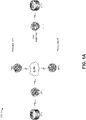
- Figs. 1A-1F are diagrams of example implementations 100 described herein.
- Implementations 100 may include multiple customer edge devices (e.g., shown as customer edge devices CE1 and CE2), multiple provider edge devices (e.g., shown as provider edge devices PE1 through PE3), and a pseudowire aggregator (PW aggregator) device.
- customer edge devices e.g., shown as customer edge devices CE1 and CE2
- provider edge devices e.g., shown as provider edge devices PE1 through PE3
- PW aggregator pseudowire aggregator
- customer edge device CE1 may be connected to provider edge device PE1, which is multi-homed with provider edge devices PE2 and PE3 over a network, such as an EVPN core; provider edge devices PE2 and PE3 may be connected to the PW aggregator via separate pseudowire connections (e.g., shown as pseudowire connections Pseudowire A and Pseudowire B); and the PW aggregator may be connected to customer edge device CE2.
- provider edge device PE1 may be connected to provider edge device PE1, which is multi-homed with provider edge devices PE2 and PE3 over a network, such as an EVPN core
- provider edge devices PE2 and PE3 may be connected to the PW aggregator via separate pseudowire connections (e.g., shown as pseudowire connections Pseudowire A and Pseudowire B); and the PW aggregator may be connected to customer edge device CE2.
- the EVPN core may be configured in single-active mode (e.g., only a single provider edge device of a plurality of provider edge devices attached to a particular Ethernet-Segment may forward traffic to and from that Ethernet Segment) or all-active mode (e.g., each of the provider edge devices of a plurality of provider edge devices attached to a particular Ethernet-Segment may forward traffic to and from the Ethernet Segment).
- single-active mode e.g., only a single provider edge device of a plurality of provider edge devices attached to a particular Ethernet-Segment may forward traffic to and from that Ethernet Segment
- all-active mode e.g., each of the provider edge devices of a plurality of provider edge devices attached to a particular Ethernet-Segment may forward traffic to and from the Ethernet Segment.
- the PW aggregator may store information (e.g., first information, first data, and/or the like) regarding pseudowire connection Pseudowire A (e.g., a first pseudowire connection) with provider edge device PE2 (e.g., a first device), where pseudowire connection Pseudowire A provides, via provider edge device PE2, access to the network to communicate with customer edge device CE1 (e.g., a host device).
- information e.g., first information, first data, and/or the like
- pseudowire connection Pseudowire A e.g., a first pseudowire connection
- provider edge device PE2 e.g., a first device
- customer edge device CE1 e.g., a host device
- the PW aggregator may store information (e.g., second information, second data, and/or the like) regarding pseudowire connection Pseudowire B (e.g., a second pseudowire connection) with provider edge device PE3 (e.g., a second device), where pseudowire connection Pseudowire B provides, via provider edge device PE3, access to the network to communicate with customer edge device CE1 (e.g., the host device).
- the pseudowire connections Pseudowire A and Pseudowire B may be terminated on the provider edge devices PE2 and PE3, respectively, over a logical interface represented as a pseudowire-subscriber interface (PS interface), such as the ps0 logical interfaces.
- PS interface pseudowire-subscriber interface
- Figs. 1B-1F assume that customer edge device CE1 wants to send a packet to customer edge device CE2.
- the description accompanying Fig. 1B describes a first scenario where the capabilities of the multi-homed provider edge devices PE2 and PE3 are coordinated with the characteristics of the pseudowire connections Pseudowire A and Pseudowire B, such that the packet may be transmitted to customer edge device CE2.
- the description accompanying Fig. 1C describes a second scenario where the capabilities of the multi-homed provider edge devices PE2 and PE3 are not coordinated with the characteristics of the pseudowire connections Pseudowire A and Pseudowire B, such that the packet may never be transmitted to customer edge device CE2.
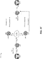
- Fig. ID describes a third scenario where the PW aggregator causes the characteristics of the pseudowire connections Pseudowire A and Pseudowire B to be coordinated with the capabilities of the multi-homed provider edge devices PE2 and PE3, such that the packet may be transmitted to customer edge device CE2.
- the description accompanying Fig. IE describes a fourth scenario where the PW aggregator causes the capabilities of the multi-homed provider edge devices PE2 and PE3 to be coordinated with the characteristics of the pseudowire connections Pseudowire A and Pseudowire B, such that the packet may be transmitted to customer edge device CE2.
- the description accompanying Fig. IE describes a fourth scenario where the PW aggregator causes the capabilities of the multi-homed provider edge devices PE2 and PE3 to be coordinated with the characteristics of the pseudowire connections Pseudowire A and Pseudowire B, such that the packet may be transmitted to customer edge device CE2.
- IF describes how the packet may be transmitted to customer edge device CE2 based on the PW aggregator causing the capabilities of the multi-homed provider edge devices PE2 and PE3 to be coordinated with the characteristics of the pseudowire connections Pseudowire A and Pseudowire B in accordance with the fourth scenario.
- a packet may be transmitted from customer edge device CE1 to customer edge device CE2 where the capabilities of the multi-homed provider edge devices PE2 and PE3 are coordinated with the characteristics of the pseudowire connections Pseudowire A and Pseudowire B.
- coordination may exist where a provider edge device that has a designated forwarder (DF) capability is connected to a pseudowire connection that is a primary pseudowire connection.
- DF forwarder
- NDF non-designated forwarder
- coordination may not exist where the provider edge device that has the DF capability is connected to the pseudowire connection that is the backup pseudowire connection or where the provider edge device that has the NDF capability is connected to the pseudowire connection that is the primary pseudowire connection.
- customer edge device CE1 may generate the packet to be sent to customer edge device CE2.
- the packet may be associated with broadcast, unicast, multicast (BUM) traffic. While some implementations are described in the context of a single packet, in reality, the implementations apply to thousands, millions, or more packets being received by various customer edge devices, provider edge devices, and/or PW aggregator devices.
- BUM broadcast, unicast, multicast
- the packet may be an Address Resolution Protocol (ARP) packet that contains an address resolution request.
- Customer edge device CE1 may send the ARP packet to determine the media access control address (MAC address) of customer edge device CE2.
- MAC address media access control address
- customer edge device CE2 may send an ARP packet that contains an address resolution reply (e.g., customer edge device CE2's MAC address) to customer edge device CE1.
- customer edge device CE1 may send the packet to provider edge device PE1. Because provider edge device PE1 is multi-homed with provider edge devices PE2 and PE3, provider edge device PE1 may forward the packet onto the network and the packet may be transmitted to provider edge devices PE2 and PE3. In this case, provider edge device PE2 may be assigned the DF capability and pseudowire connection Pseudowire A may be the primary pseudowire connection between the PW aggregator and provider edge devices PE2 and PE3. Because the capability of provider edge device PE2 is coordinated with the characteristic of pseudowire connection Pseudowire A, provider edge device PE2 may forward the packet to the pseudowire connection Pseudowire A, which may transmit the packet to the PW aggregator.
- provider edge device PE3 may be assigned the NDF capability and pseudowire connection Pseudowire B may be the backup pseudowire connection between the PW aggregator and provider edge devices PE2 and PE3.
- Provider edge device PE3 therefore may prevent the packet from being forwarded by provider edge device PE3 because the provider edge device PE3 has the NDF capability and the provider edge device PE3 is connected to backup pseudowire connection Pseudowire B.
- the PW aggregator may send, based on receiving the packet from provider edge device PE2 via pseudowire connection Pseudowire A, the packet to the customer edge device CE2.
- a packet may fail to be transmitted from customer edge device CE1 to customer edge device CE2 because the capabilities of the multi-homed provider edge devices PE2 and PE3 are not coordinated with the characteristics of the pseudowire connections Pseudowire A and Pseudowire B.
- customer edge device CE1 may send a packet that is destined for customer edge device CE2 in a similar manner as that described herein (e.g., see the description accompanying Fig. 1B ).
- provider edge device PE2 may be assigned the DF capability and therefore may be configured to forward the packet to the PW aggregator via the pseudowire connection Pseudowire A.
- pseudowire connection Pseudowire A may be the backup pseudowire connection between the PW aggregator and provider edge devices PE2 and PE3, so provider edge device PE2, which may be configured to forward the packet on only a primary pseudowire connection, may not forward the packet on pseudowire connection Pseudowire A to the PW aggregator.
- provider edge device PE3 may be assigned the NDF capability and therefore may be configured to prevent forwarding of the packet even though provider edge device PE2 is connected to pseudowire connection Pseudowire B, which may be the primary pseudowire connection, and provider edge device PE2 may be configured to forward the packet on a primary pseudowire connection.
- Pseudowire B which may be the primary pseudowire connection
- provider edge device PE2 may be configured to forward the packet on a primary pseudowire connection.
- the capabilities of the multi-homed provider edge devices PE2 and PE3 are not coordinated with the characteristics of the pseudowire connections Pseudowire A and Pseudowire B, so the multihomed provider edge devices may never forward the packet to the PW aggregator and therefore the packet may never arrive at the customer edge device CE2.
- the provider edge device that has the DF capability may send a message to the PW aggregator to ensure the characteristics of the pseudowire connections Pseudowire A and Pseudowire B are coordinated with the capabilities of the multi-homed provider edge devices PE2 and PE3.
- the provider edge device that has the DF capability may send the message at a scheduled time (e.g., at a particular time interval, such as every 10 seconds), upon a change in the capability of the provider edge device (e.g., the provider edge device changes from a provider edge device with an NDF capability to a provider edge device with a DF capability), upon receiving a packet addressed to a particular customer edge device (e.g., the provider edge device receives a packet to be transmitted to a customer edge device via a pseudowire connection), and/or the like.
- a scheduled time e.g., at a particular time interval, such as every 10 seconds
- the provider edge device changes from a provider edge device with an NDF capability to a provider edge device with a DF capability
- the provider edge device receives a packet to be transmitted to a customer edge device via a pseudowire connection
- the provider edge device that has the DF capability may send the message to the PW aggregator to ensure the characteristics of the pseudowire connections Pseudowire A and Pseudowire B are coordinated with the capabilities of the multi-homed provider edge devices PE2 and PE3 so that one or more packets may be sent from customer edge device CE1 to customer edge device CE2.
- provider edge device PE2 has the DF capability and may generate a message that includes a configuration identifier that indicates the capability of provider edge device PE2.
- provider edge device PE2 may generate a message that includes the configuration identifier, which indicates that provider edge device PE2 has the DF capability for the network.
- the message may be a type-length-value (TLV) message.
- TLV type-length-value
- the TLV message may include a field that indicates the status of a pseudowire connection (e.g., a "PW Status" field), a field that provides additional status information (e.g., a "Status Code” field), and/or a field indicating the size of the additional status information (e.g., a "Length” field).
- the message may be a TLV message that includes a 4-octet bit Status Code field, where the configuration identifier is represented by one or more bits in the Status Code field.
- the TLV message may include the configuration identifier and/or information regarding pseudowire connection Pseudowire A, such as the status of pseudowire connection Pseudowire A, a characteristic of pseudowire connection Pseudowire A (e.g., whether pseudowire connection Pseudowire A is the primary pseudowire connection or the backup pseudowire connection), information concerning Operations, Administration, and Maintenance (OAM) of pseudowire connection Pseudowire A, and/or the like.
- provider edge device PE2 may send the message to the PW aggregator. For example, provider edge device PE2 may send the message to the PW aggregator via pseudowire connection Pseudowire A.
- provider edge device PE2 may send the message to the PW aggregator via a pseudowire connection, regardless of whether the pseudowire connection is a primary pseudowire connection or a backup pseudowire connection.
- provider edge device PE2 may send the message to the PW aggregator via pseudowire connection Pseudowire A, which may be the backup pseudowire connection, as shown in Fig. ID.
- the PW aggregator may receive the message from provider edge device PE2. For example, the PW aggregator may receive the message that includes the configuration identifier from provider edge device PE2 via pseudowire connection Pseudowire A. In some implementations, the PW aggregator may detect the type of the message (e.g., a TLV message) and determine, based on the detected type, that the message should be parsed. In some implementations, the PW aggregator may parse the message to determine and/or identify the configuration identifier. In some implementations, the PW aggregator may detect the type of the message (e.g., a TLV message) and determine, based on the detected type, the configuration identifier. For example, the PW aggregator may detect that the message is a TLV message and determine the configuration identifier that indicates that provider edge device PE2 has the DF capability based on reading the Status Code field of the TLV message.
- the type of the message e.g., a TLV message
- the PW aggregator may change the characteristic (e.g., a first characteristic) of pseudowire connection Pseudowire A and the characteristic (e.g., a second characteristic) of pseudowire connection Pseudowire B based on the configuration identifier included in the message. For example, where the configuration identifier indicates that provider edge device PE2 has the DF capability, the PW aggregator may change the characteristic of pseudowire connection Pseudowire A from indicating that pseudowire connection Pseudowire A is the backup pseudowire connection to indicating that pseudowire connection Pseudowire A is the primary pseudowire connection.
- the configuration identifier indicates that provider edge device PE2 has the DF capability
- the PW aggregator may change the characteristic of pseudowire connection Pseudowire B from indicating that pseudowire connection Pseudowire B is the primary pseudowire connection to indicating that pseudowire connection Pseudowire B is the backup pseudowire connection. Based on changing the characteristic of pseudowire connection Pseudowire A and changing the characteristic of pseudowire connection Pseudowire B, the PW aggregator may receive the one or more packets sent from customer edge device CE1, forwarded by provider edge device PE1, and forwarded by provider edge device PE2 via pseudowire connection Pseudowire A.
- the provider edge device that has the NDF capability may send an additional message to the PW aggregator, in a similar manner as described elsewhere herein with regard to the provider edge device that has the DF capability, to ensure the characteristics of the pseudowire connections Pseudowire A and Pseudowire B are coordinated with the capabilities of the multi-homed provider edge devices PE2 and PE3.
- provider edge device PE3, which has the NDF capability may send the additional message to the PW aggregator via pseudowire connection Pseudowire B, which is the primary pseudowire connection.
- the additional message sent by the provider edge device that has the NDF capability may include similar information and may be formatted in a similar manner, as described elsewhere herein, as the message sent by the provider edge device that has the DF capability.
- the provider edge device PE3 may generate a message that is a TLV message that includes a configuration identifier that indicates the capability of provider edge device PE3.
- the PW aggregator may receive the additional message sent by the provider edge device that has the NDF capability, may determine and/or identify the configuration identifier that indicates the capability of the provider edge device that has the NDF capability, and may change the characteristic of pseudowire connection Pseudowire A and the characteristic of pseudowire connection Pseudowire B, if necessary, in a similar manner as described elsewhere herein with regard to the message sent by the provider edge device with the DF capability.
- the PW aggregator may receive the message from provider edge device PE3, which has the NDF capability, may determine and/or identify the configuration identifier that indicates the capability of provider edge device PE3, and, if necessary, may change the characteristic of pseudowire connection Pseudowire A to indicate that pseudowire connection Pseudowire A is the primary pseudowire connection and the characteristic of pseudowire connection Pseudowire B to indicate that pseudowire connection Pseudowire B is the backup pseudowire connection.
- the characteristics of the pseudowire connections Pseudowire A and Pseudowire B are coordinated with the capabilities of the multi-homed provider edge devices PE2 and PE3.
- the PW aggregator makes changes to the characteristics of the pseudowire connections, the one or more packets may be successfully transmitted from customer edge device CE1 to customer edge device CE2 in a similar manner as described herein (see, e.g., the description corresponding to Fig. 1B ).
- the PW aggregator may receive the one or more packets sent from customer edge device CE1, forwarded by provider edge device PE1, and sent from provider edge device PE2, which has the DF capability, via pseudowire connection Pseudowire A, which has now been changed to the primary pseudowire connection because of the message indicating that provider edge device PE2 has the DF capability and/or the additional message indicating that provider edge device PE3 has the NDF capability.
- the PW aggregator may then send the one or more packets to the customer edge device CE2.
- the capabilities of the multi-homed provider edge devices may change over time because of changing network dynamics (e.g., a provider edge device goes offline, a new customer edge device is added to the network, a pseudowire connection fails, and/or the like).
- provider edge device PE2 may have the DF capability for a first period of time and then may have the NDF capability for a second period of time based on changing conditions of the network.
- provider edge device PE3 may have the NDF capability for the first period of time and may have the DF capability for the second period of time.
- a provider edge device may send a message to the PW aggregator after the provider edge device determines that the provider edge device has the DF capability.
- provider edge device PE2 which may initially have the DF capability, may send a message to the PW aggregator via pseudowire connection Pseudowire A at the beginning of the first period of time
- provider edge device PE3, which may subsequently have the DF capability may send a new message to the PW aggregator via pseudowire connection Pseudowire B at the beginning of the second period of time.
- the message may include the configuration identifier that indicates that provider edge device PE2 has the DF capability for the network and the new message may include a new configuration identifier that indicates that provider edge device PE3 has the DF capability for the network.
- the PW aggregator may receive the message and perform similar operations to those described elsewhere herein to change the characteristics of the pseudowire connection Pseudowire A and Pseudowire B. For example, after receiving the message from the provider edge device PE2 via the pseudowire connection Pseudowire A, the PW aggregator may change the characteristics of the pseudowire connections Pseudowire A and Pseudowire B (e.g., to identify Pseudowire A as the primary pseudowire and Pseudowire B as the backup pseudowire) to receive data sent from the customer edge device CE1 via pseudowire connection Pseudowire A.
- the PW aggregator may change the characteristics of the pseudowire connections Pseudowire A and Pseudowire B (e.g., to identify Pseudowire A as the primary pseudowire and Pseudowire B as the backup pseudowire) to receive data sent from the customer edge device CE1 via pseudowire connection Pseudowire A.
- the PW aggregator may receive the new message and perform similar operations to those described herein to change the characteristics of the pseudowire connection Pseudowire A and Pseudowire B. For example, after receiving the new message from the provider edge device PE3 via the pseudowire connection Pseudowire B, the PW aggregator may change the characteristics of the pseudowire connections Pseudowire A and Pseudowire B (e.g., to identify Pseudowire A as the backup pseudowire and Pseudowire B as the primary pseudowire) to receive new data sent from the customer edge device CE1 via pseudowire connection Pseudowire B.
- the PW aggregator may change the characteristics of the pseudowire connections Pseudowire A and Pseudowire B (e.g., to identify Pseudowire A as the backup pseudowire and Pseudowire B as the primary pseudowire) to receive new data sent from the customer edge device CE1 via pseudowire connection Pseudowire B.
- the PW aggregator may send a first message to provider edge device PE2 and/or a second message to provider edge device PE3 to ensure that the capabilities of the multihomed provider edge devices PE2 and PE3 are coordinated with the characteristics of the pseudowire connections Pseudowire A and Pseudowire B.
- the PW aggregator may send the first message and/or the second message at a scheduled time (e.g., a regular time interval, such as every 10 seconds), upon a change in the characteristic of the pseudowire connection Pseudowire A and/or a change in the characteristic of the pseudowire connection Pseudowire B (e.g., pseudowire connection Pseudowire A changes from a backup pseudowire connection to a primary pseudowire connection, pseudowire connection Pseudowire B changes from a primary pseudowire connection to a backup pseudowire connection, and/or the like), upon receiving a packet addressed to a particular customer edge device (e.g., the PW aggregator receives a packet to be transmitted to a customer edge device via a pseudowire connection), and/or the like.
- a scheduled time e.g., a regular time interval, such as every 10 seconds
- the PW aggregator may send a first message to provider edge device PE2 and/or a second message to provider edge device PE3 to ensure that the capabilities of the multi-homed provider edge devices PE2 and PE3 are coordinated with the characteristics of the pseudowire connections Pseudowire A and Pseudowire B so that one or more packets may be sent from customer edge device CE1 to customer edge device CE2.
- the PW aggregator may determine information that indicates a characteristic of pseudowire connection Pseudowire A (e.g., whether pseudowire connection Pseudowire A is the primary pseudowire connection or the backup pseudowire connection). In some implementations, the PW aggregator may determine the information that indicates the characteristic of pseudowire connection Pseudowire A based on the information regarding pseudowire connection Pseudowire A stored by the PW aggregator. Similarly, the PW aggregator may determine information that indicates a characteristic of pseudowire connection Pseudowire B (e.g., whether pseudowire connection Pseudowire B is the primary pseudowire connection or the backup pseudowire connection). In some implementations, the PW aggregator may determine the information that indicates the characteristic of pseudowire connection Pseudowire B based on the information regarding pseudowire connection Pseudowire B stored by the PW aggregator.
- the PW aggregator may generate a first message that includes the information that indicates the characteristic of pseudowire connection Pseudowire A. For example, the PW aggregator may generate the first message that includes the information that indicates that pseudowire connection Pseudowire A is the backup pseudowire connection. Additionally, the PW aggregator may generate a second message that includes the information that indicates the characteristic of pseudowire connection Pseudowire B. For example, the PW aggregator may generate the second message that includes the information that indicates that pseudowire connection Pseudowire B is the primary pseudowire connection.
- the first message may be a TLV message.
- the TLV message may include a field that indicates the status of a pseudowire connection (e.g., a "PW Status" field), a field that provides additional status information (e.g., a "Status Code” field), and/or a field indicating the size of the additional status information (e.g., a "Length” field).
- the first message may be a TLV message that has a PW Status field that indicates the characteristic of pseudowire connection Pseudowire A.
- the first message may be a TLV message that includes information regarding pseudowire connection Pseudowire A, such as the status of pseudowire connection Pseudowire A, the characteristic of pseudowire connection Pseudowire A (e.g., whether pseudowire connection Pseudowire A is the primary pseudowire connection or the backup pseudowire connection), information concerning OAM of pseudowire connection Pseudowire A, and/or the like.
- the second message may be a TLV message that has a PW Status field that indicates the characteristic of pseudowire connection Pseudowire B.
- the second message may be a TLV message that includes information regarding pseudowire connection Pseudowire B, such as the status of pseudowire connection Pseudowire B, the characteristic of pseudowire connection Pseudowire B (e.g., whether pseudowire connection Pseudowire B is the primary pseudowire connection or the backup pseudowire connection), information concerning OAM of pseudowire connection Pseudowire B, and/or the like.
- pseudowire connection Pseudowire B such as the status of pseudowire connection Pseudowire B, the characteristic of pseudowire connection Pseudowire B (e.g., whether pseudowire connection Pseudowire B is the primary pseudowire connection or the backup pseudowire connection), information concerning OAM of pseudowire connection Pseudowire B, and/or the like.
- the PW aggregator may send the first message to provider edge device PE2. For example, the PW aggregator may send the first message to the provider edge device PE2 via pseudowire connection Pseudowire A. In some implementations, the PW aggregator may send the first message to provider edge device PE2 via pseudowire connection Pseudowire A, regardless of whether pseudowire connection Pseudowire A is the primary pseudowire connection or the backup pseudowire connection. As shown by reference number 116, the PW aggregator may send the second message to provider edge device PE3. For example, the PW aggregator may send the second message to the provider edge device PE3 via pseudowire connection Pseudowire B. In some implementations, the PW aggregator may send the second message to provider edge device PE3 via pseudowire connection Pseudowire B, regardless of whether pseudowire connection Pseudowire B is the primary pseudowire connection or the backup pseudowire connection.
- provider edge device PE2 may receive the first message from the PW aggregator. In some implementations, provider edge device PE2 may receive the first message from the PW aggregator via pseudowire connection Pseudowire A. In some implementations, provider edge device PE2 may parse the first message to determine and/or identify the information that indicates the characteristic of pseudowire connection Pseudowire A. Additionally, provider edge device PE2 may change the capability of the provider edge device PE2 based on the information that indicates the characteristic of pseudowire connection Pseudowire A. For example, the provider edge device PE2 may change the provider edge device PE2 to have an NDF capability from a DF capability based on the information included in the first message that indicates that pseudowire connection Pseudowire A is the backup pseudowire connection.
- provider edge device PE3 may receive the second message from the PW aggregator. In some implementations, provider edge device PE3 may receive the second message from the PW aggregator via pseudowire connection Pseudowire B. In some implementations, provider edge device PE3 may parse the second message to determine and/or identify the information that indicates the characteristic of pseudowire connection Pseudowire B. Additionally, provider edge device PE3 may change the capability of the provider edge device PE3 based on the information that indicates the characteristic of pseudowire connection Pseudowire B. For example, the provider edge device PE3 may change the provider edge device PE3 to have a DF capability from an NDF capability based on the information included in the second message that indicates that pseudowire connection Pseudowire B is the primary pseudowire connection.
- the capabilities of the multi-homed provider edge devices PE2 and PE3 are coordinated with the characteristics of the pseudowire connections Pseudowire A and Pseudowire B.
- the one or more packets may be successfully transmitted from customer edge device CE1 to customer edge device CE2.
- the characteristics of the pseudowire connections may change over time because of changing network dynamics (e.g., a provider edge device goes offline, a new customer edge device is added to the network, a pseudowire connection fails, and/or the like).
- pseudowire connection Pseudowire A may be the backup pseudowire connection for a first period of time and then may be the primary pseudowire connection for a second period of time based on the changing conditions of the network.
- pseudowire connection B may be the primary pseudowire connection for the first period of time and then may be the backup pseudowire connection for the second period of time.
- the PW aggregator may send the first message to the provider edge device PE1 and the second message to the provider edge device PE2 after the PW aggregator determines that the characteristic of pseudowire connection Pseudowire A has changed and/or the characteristic of pseudowire connection Pseudowire B has changed. For example, the PW aggregator may send the first message to provider edge device PE2, via pseudowire connection Pseudowire A, and may send the second message to provider edge device PE3, via pseudowire connection Pseudowire B, at the beginning of the first period of time.
- the PW aggregator may send a third message to provider edge device PE2, via pseudowire connection Pseudowire A, and may send a fourth message to provider edge device PE3, via pseudowire connection Pseudowire B, at the beginning of the second period of time.
- the first message may include the information that indicates the characteristic of pseudowire connection Pseudowire A (e.g., that pseudowire connection Pseudowire A is the backup pseudowire connection) and the second message may include the information that indicates the characteristic of pseudowire connection Pseudowire B (e.g., that pseudowire connection Pseudowire B is the primary pseudowire connection).
- the third message may include information that indicates a new characteristic of pseudowire connection Pseudowire A (e.g., that pseudowire connection Pseudowire A is the primary pseudowire connection) and the fourth message may include information that indicates a new characteristic of pseudowire connection Pseudowire B (e.g., that pseudowire connection Pseudowire B is the backup pseudowire connection).
- pseudowire connection Pseudowire A e.g., that pseudowire connection Pseudowire A is the primary pseudowire connection
- the fourth message may include information that indicates a new characteristic of pseudowire connection Pseudowire B (e.g., that pseudowire connection Pseudowire B is the backup pseudowire connection).
- provider edge device PE2 may receive the first message and provider edge device PE3 may receive the second message, and each may perform similar steps to those described elsewhere herein to change the capabilities of provider edge devices PE2 and PE3.
- provider edge device PE2 may receive the third message and provider edge device PE3 may receive the fourth message, and each may perform similar steps to those described elsewhere herein to change the capabilities of provider edge devices PE2 and PE3.
- the PW aggregator may receive data on the pseudowire connections based on sending the first message, second message, third message, and fourth message. For example, the PW aggregator may receive data from the customer edge device CE1 via pseudowire connection Pseudowire B after sending the first message and the second message. As another example, the PW aggregator may receive the data from the customer edge device CE1 via pseudowire connection Pseudowire A after sending the third message and the fourth message.
- a packet may be transmitted from customer edge device CE1 to customer edge device CE2 after the capabilities of the multi-homed provider edge devices PE2 and PE3 are coordinated with the characteristics of the pseudowire connections Pseudowire A and Pseudowire B
- customer edge device CE1 may send a packet that is destined for customer edge device CE2 in a similar manner as that described herein (e.g., see the description accompanying Fig. 1B ). In this case, the packet may be received by provider edge device PE1 and forwarded to provider edge devices PE2 and PE3.
- provider edge device PE2 had the DF capability and provider edge device PE3 had the NDF capability, but the capabilities of provider edge devices PE2 and PE3 were not coordinated with pseudowire connections Pseudowire A (e.g., the backup pseudowire connection) and pseudowire connection Pseudowire B (e.g., the primary pseudowire connection).
- the PW aggregator sent the first message to provider edge device PE2, which caused provider edge device PE2 to change the provider edge device PE2 to have the NDF capability from the DF capability, and sent the second message to provider edge device PE3, which caused provider edge device PE3 to change the provider edge device PE3 to have the DF capability from the NDF capability.
- provider edge devices P2 and P3 may now be coordinated with pseudowire connections Pseudowire A and Pseudowire B. Therefore, the packet may be sent from the provider edge device PE3 and transmitted on pseudowire connection Pseudowire B to the PW aggregator, which may forward the packet to customer edge device CE2.
- the packet may be routed from customer edge device CE1 to customer edge device CE2 where the multihomed provider edge devices are coordinated with the pseudowire connections.
- FIG. 1B shows that the packet may be routed via provider edge device PE2 and pseudowire connection Pseudowire A to the PW aggregator when provider edge device PE2 has the DF capability and pseudowire connection Pseudowire A is the primary pseudowire connection.
- Fig. IE shows that the packet may be routed via provider edge device PE3 and pseudowire connection Pseudowire B to the PW aggregator when provider edge device PE3 has the DF capability and pseudowire connection Pseudowire B is the primary pseudowire connection.
- Some implementations described herein increase network reliability by ensuring that packets sent from one customer edge device to another customer edge device are not lost due to lack of coordination of provider edge device capabilities with pseudowire connection characteristics. Furthermore, some implementations described herein reduce waste of processing and memory resources of devices in the network by ensuring that packets reach their intended destination and do not need to be resent. In this way, devices in the network are able to handle more packets because the network is more efficient, thus increasing their productivity and minimizing costs of network operators who would otherwise have to install and maintain additional devices on the network.
- FIGS. 1A-1F are provided merely as examples. Other examples are possible and may differ from what was described with regard to Figs. 1A-1F .
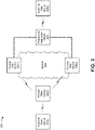
- Fig. 2 is a diagram of an example environment 200 in which systems and/or methods, described herein, may be implemented.
- environment 200 may include customer edge device 210-1 and customer edge device 210-2 (hereinafter referred to collectively as “customer edge devices 210," and individually as “customer edge device 210"); provider edge device 220-1, provider edge device 220-2, and provider edge device 220-3 (hereinafter referred to collectively as “provider edge devices 220,” and individually as “provider edge device 220”); a pseudowire aggregator device 230; and a network 240.
- Devices of environment 200 may interconnect via wired connections, wireless connections, or a combination of wired and wireless connections.
- Customer edge device 210 includes one or more devices (e.g., one or more traffic transfer devices) capable of processing and/or transferring traffic.
- customer edge device 210 may include a firewall, a router, a gateway, a switch, a hub, a bridge, a reverse proxy, a server (e.g., a proxy server), a security device, an intrusion detection device, a load balancer, or a similar type of device.
- customer edge device 210 may transmit traffic to provider edge device 220 and receive traffic from pseudowire aggregator device 230, as described elsewhere herein.
- customer edge device 210 may be a physical device implemented within a housing, such as a chassis.
- customer edge device 210 may be a virtual device implemented by one or more computer devices of a cloud computing environment or a data center.
- Provider edge device 220 includes one or more devices (e.g., one or more traffic transfer devices) capable of processing and/or transferring traffic.
- provider edge device 220 may include a firewall, a router, a gateway, a switch, a hub, a bridge, a reverse proxy, a server (e.g., a proxy server), a security device, an intrusion detection device, a load balancer, or a similar type of device.
- provider edge device 220 may receive traffic from customer edge device 210 and may transmit the traffic to another provider edge device 220 and/or to pseudowire aggregator device 230, as described elsewhere herein.
- provider edge device 220 may be a physical device implemented within a housing, such as a chassis.
- provider edge device 220 may be a virtual device implemented by one or more computer devices of a cloud computing environment or a data center.
- Pseudowire aggregator device 230 includes one or more devices (e.g., one or more traffic transfer devices) capable of processing and/or transferring traffic via one or more pseudowire connections.
- pseudowire aggregator device 230 may include a firewall, a router, a gateway, a switch, a hub, a bridge, a reverse proxy, a server (e.g., a proxy server), a security device, an intrusion detection device, a load balancer, or a similar type of device.
- pseudowire aggregator device 230 may receive a packet from provider edge device 220 via a pseudowire connection and may send the packet to one or more other customer edge devices, as described elsewhere herein.
- pseudowire aggregator device 230 may be a physical device implemented within a housing, such as a chassis. In some implementations, pseudowire aggregator device 230 may be a virtual device implemented by one or more computer devices of a cloud computing environment or a data center.
- Network 240 includes one or more wired and/or wireless networks.
- network 240 may include a cellular network (e.g., a long-term evolution (LTE) network, a 3G network, or a code division multiple access (CDMA) network), a public land mobile network (PLMN), a local area network (LAN), a wide area network (WAN), a metropolitan area network (MAN), a telephone network (e.g., the Public Switched Telephone Network (PSTN)), an Ethernet network, an Ethernet virtual private network (EVPN), a private network, an ad hoc network, an intranet, the Internet, a fiber optic-based network, a cloud computing network, or the like, and/or a combination of these or other types of networks.
- LTE long-term evolution
- CDMA code division multiple access
- PLMN public land mobile network
- LAN local area network
- WAN wide area network
- MAN metropolitan area network
- PSTN Public Switched Telephone Network
- EVPN Ethernet virtual private network
- the number and arrangement of devices and networks shown in Fig. 2 are provided as an example. In practice, there may be additional devices and/or networks, fewer devices and/or networks, different devices and/or networks, or differently arranged devices and/or networks than those shown in Fig. 2 . Furthermore, two or more devices shown in Fig. 2 may be implemented within a single device, or a single device shown in Fig. 2 may be implemented as multiple, distributed devices. Additionally, or alternatively, a set of devices (e.g., one or more devices) of environment 200 may perform one or more functions described as being performed by another set of devices of environment 200.
- Fig. 3 is a diagram of example components of a device 300.
- Device 300 may correspond to customer edge device 210, provider edge device 220, and/or pseudowire aggregator device 230.
- customer edge device 210, provider edge device 220, and/or pseudowire aggregator device 230 may include one or more devices 300 and/or one or more components of device 300. As shown in Fig.
- device 300 may include one or more input components 305-1 through 305-B (B ⁇ 1) (hereinafter referred to collectively as “input components 305,” and individually as “input component 305"), a switching component 310, one or more output components 315-1 through 315-C (C ⁇ 1) (hereinafter referred to collectively as “output components 315,” and individually as “output component 315"), and a controller 320.
- Input component 305 may be points of attachment for physical links and may be points of entry for incoming traffic, such as packets. Input component 305 may process incoming traffic, such as by performing data link layer encapsulation or decapsulation. In some implementations, input component 305 may send and/or receive packets. In some implementations, input component 305 may include an input line card that includes one or more packet processing components (e.g., in the form of integrated circuits), such as one or more interface cards (IFCs), packet forwarding components, line card controller components, input ports, processors, memories, and/or input queues. In some implementations, device 300 may include one or more input components 305.
- packet processing components e.g., in the form of integrated circuits
- IFCs interface cards
- packet forwarding components line card controller components
- input ports e.g., processors, memories, and/or input queues.
- device 300 may include one or more input components 305.
- Switching component 310 may interconnect input components 305 with output components 315.
- switching component 310 may be implemented via one or more crossbars, via busses, and/or with shared memories.
- the shared memories may act as temporary buffers to store packets from input components 305 before the packets are eventually scheduled for delivery to output components 315.
- switching component 310 may enable input components 305, output components 315, and/or controller 320 to communicate.
- Output component 315 may store packets and may schedule packets for transmission on output physical links. Output component 315 may support data link layer encapsulation or decapsulation, and/or a variety of higher-level protocols. In some implementations, output component 315 may send packets and/or receive packets. In some implementations, output component 315 may include an output line card that includes one or more packet processing components (e.g., in the form of integrated circuits), such as one or more IFCs, packet forwarding components, line card controller components, output ports, processors, memories, and/or output queues. In some implementations, device 300 may include one or more output components 315. In some implementations, input component 305 and output component 315 may be implemented by the same set of components (e.g., and input/output component may be a combination of input component 305 and output component 315).
- Controller 320 includes a processor in the form of, for example, a central processing unit (CPU), a graphics processing unit (GPU), an accelerated processing unit (APU), a microprocessor, a microcontroller, a digital signal processor (DSP), a field-programmable gate array (FPGA), an application-specific integrated circuit (ASIC), and/or another type of processor.
- the processor is implemented in hardware, firmware, or a combination of hardware and software.
- controller 320 may include one or more processors that can be programmed to perform a function.
- controller 320 may include a random access memory (RAM), a read only memory (ROM), and/or another type of dynamic or static storage device (e.g., a flash memory, a magnetic memory, an optical memory, etc.) that stores information and/or instructions for use by controller 320.
- RAM random access memory
- ROM read only memory
- static storage device e.g., a flash memory, a magnetic memory, an optical memory, etc.
- controller 320 may communicate with other devices, networks, and/or systems connected to device 300 to exchange information regarding network topology. Controller 320 may create routing tables based on the network topology information, create forwarding tables based on the routing tables, and forward the forwarding tables to input components 305 and/or output components 315. Input components 305 and/or output components 315 may use the forwarding tables to perform route lookups for incoming and/or outgoing packets.
- Controller 320 may perform one or more processes described herein. Controller 320 may perform these processes in response to executing software instructions stored by a computer-readable medium.
- a computer-readable medium may be a non-transitory memory device.
- a memory device includes memory space within a single physical storage device or memory space spread across multiple physical storage devices. Additionally or alternatively a computer-readable medium may include transient media such as carrier signals and transmission media.
- Software instructions may be read into a memory and/or storage component associated with controller 320 from another computer-readable medium or from another device via a communication interface. When executed, software instructions stored in a memory and/or storage component associated with controller 320 may cause controller 320 to perform one or more processes described herein. Additionally, or alternatively, hardwired circuitry may be used in place of or in combination with software instructions to perform one or more processes described herein. Thus, implementations described herein are not limited to any specific combination of hardware circuitry and software.
- device 300 may include additional components, fewer components, different components, or differently arranged components than those shown in Fig. 3 . Additionally, or alternatively, a set of components (e.g., one or more components) of device 300 may perform one or more functions described as being performed by another set of components of device 300.
- a set of components e.g., one or more components
- Fig. 4 is a flow chart of an example process 400 for coordinating pseudowire connection characteristics and multi-homed provider edge device capabilities.
- one or more process blocks of Fig. 4 may be performed by a pseudowire aggregator device (e.g., pseudowire aggregator device 230).
- one or more process blocks of Fig. 4 may be performed by another device or a group of devices separate from or including the pseudowire aggregator device (e.g., pseudowire aggregator device 230), such as a customer edge device (e.g., customer edge device 210) and a provider edge device (e.g., provider edge device 220).
- process 400 may include storing first information regarding a first pseudowire connection with a first device, wherein the first pseudowire connection provides, via the first device, access to an Ethernet virtual private network (EVPN) to communicate with a host device (block 410).
- the pseudowire aggregator device e.g., using input component 305, switching component 310, output component 315, controller 320, and/or the like
- the first pseudowire connection may provide, via the first device, access to an Ethernet virtual private network (EVPN) to communicate with a host device.
- EVPN Ethernet virtual private network
- process 400 may include storing second information regarding a second pseudowire connection with a second device, wherein the second pseudowire connection provides, via the second device, access to the EVPN to communicate with the host device (block 420).
- the pseudowire aggregator device e.g., using input component 305, switching component 310, output component 315, controller 320, and/or the like
- the second pseudowire connection may provide access, via the second device, to the EVPN to communicate with the host device.
- process 400 may include receiving a message that includes a configuration identifier, wherein the configuration identifier indicates that the first device has a designated forwarder capability for the EVPN (block 430).
- the pseudowire aggregator device e.g., using input component 305, switching component 310, output component 315, controller 320, and/or the like
- the configuration identifier may indicate that the first device has a designated forwarder capability for the EVPN.
- process 400 may include identifying the configuration identifier included in the message (block 440).
- the pseudowire aggregator device e.g., using input component 305, switching component 310, output component 315, controller 320, and/or the like
- process 400 may include changing a first characteristic of the first pseudowire connection with the first device based on the configuration identifier included in the message (block 450).
- the pseudowire aggregator device e.g., using input component 305, switching component 310, output component 315, controller 320, and/or the like
- process 400 may include changing a second characteristic of the second pseudowire connection with the second device based on the configuration identifier included in the message (block 460).
- the pseudowire aggregator device e.g., using input component 305, switching component 310, output component 315, controller 320, and/or the like
- process 400 may include receiving data from the host device based on changing the first characteristic of the first pseudowire connection and changing the second characteristic of the second pseudowire connection (block 470).
- the pseudowire aggregator device e.g., using input component 305, switching component 310, output component 315, controller 320, and/or the like
- Process 400 may include additional implementations, such as any single implementation or any combination of implementations described below and/or in connection with one or more other processes described elsewhere herein.
- the EVPN may be configured in single-active mode.
- the pseudowire aggregator device when changing the first characteristic of the first pseudowire connection with the first device based on the configuration identifier included in the message, the pseudowire aggregator device may change the first characteristic of the first pseudowire connection with the first device to indicate that the first pseudowire connection with the first device is a primary pseudowire connection.
- the message may be a type-length-value (TLV) message.
- the message may include status information regarding the first pseudowire connection with the first device.
- the pseudowire aggregator device may receive a new message that includes a new configuration identifier, where the new configuration identifier indicates that the second device has the designated forwarder capability for the EVPN. Additionally, the pseudowire aggregator device may identify the new configuration identifier included in the message, may change the first characteristic of the first pseudowire connection with the first device based on the new configuration identifier included in the new message, may change the second characteristic of the second pseudowire connection with the second device based on the new configuration identifier included in the new message, and may receive new data from the host device based on changing the first characteristic of the first pseudowire connection and changing the second characteristic of the second pseudowire connection.
- the message may be received via the first pseudowire connection with the first device and the new message may be received via the second pseudowire connection with the second device.
- the pseudowire aggregator device when receiving the data from the host device, may receive the data from the host device via the first pseudowire connection with the first device. Additionally, when receiving the new data from the host device, the pseudowire aggregator device may receive the new data from the host device via the second pseudowire connection with the second device.
- process 400 may include additional blocks, fewer blocks, different blocks, or differently arranged blocks than those depicted in Fig. 4 . Additionally, or alternatively, two or more of the blocks of process 400 may be performed in parallel.
- Fig. 5 is a flow chart of an example process 500 for coordinating pseudowire connection characteristics and multi-homed provider edge device capabilities.
- one or more process blocks of Fig. 5 may be performed by a pseudowire aggregator device (e.g., pseudowire aggregator device 230).
- one or more process blocks of Fig. 5 may be performed by another device or a group of devices separate from or including the pseudowire aggregator device (e.g., pseudowire aggregator device 230), such as a customer edge device (e.g., customer edge device 210) and a provider edge device (e.g., provider edge device 220).
- process 500 may include storing first data regarding a first pseudowire connection with a first device, wherein the first pseudowire connection provides, via the first device, access to an Ethernet virtual private network (EVPN) to communicate with a host device (block 510).
- the pseudowire aggregator device e.g., using input component 305, switching component 310, output component 315, controller 320, and/or the like
- the first pseudowire connection may provide, via the first device, access to an Ethernet virtual private network (EVPN) to communicate with a host device.
- EVPN Ethernet virtual private network
- process 500 may include storing second data regarding a second pseudowire connection with a second device, wherein the second pseudowire connection provides, via the second device, access to the EVPN to communicate with the host device (block 520).
- the pseudowire aggregator device e.g., using input component 305, switching component 310, output component 315, controller 320, and/or the like
- the second pseudowire connection may provide access, via the second device, to the EVPN to communicate with the host device.
- process 500 may include determining first information that indicates a first characteristic of the first pseudowire connection (block 530).
- the pseudowire aggregator device e.g., using input component 305, switching component 310, output component 315, controller 320, and/or the like
- process 500 may include determining second information that indicates a second characteristic of the second pseudowire connection (block 540).
- the pseudowire aggregator device e.g., using input component 305, switching component 310, output component 315, controller 320, and/or the like
- process 500 may include sending a first message that includes the first information, to the first device, via the first pseudowire connection, wherein the first message causes the first device to change a first capability of the first device (block 550).
- the pseudowire aggregator device e.g., using input component 305, switching component 310, output component 315, controller 320, and/or the like
- the first message may cause the first device to change a first capability of the first device.
- process 500 may include sending a second message that includes the second information, to the second device, via the second pseudowire connection, wherein the second message causes the second device to change a second capability of the second device (block 560).
- the pseudowire aggregator device e.g., using input component 305, switching component 310, output component 315, controller 320, and/or the like
- the second message may cause the second device to change a second capability of the second device.
- process 500 may include receiving data from the host device via the first pseudowire connection or the second pseudowire connection after sending the first message and sending the second message (block 570).
- the pseudowire aggregator device e.g., using input component 305, switching component 310, output component 315, controller 320, and/or the like
- Process 500 may include additional implementations, such as any single implementation or any combination of implementations described below and/or in connection with one or more other processes described elsewhere herein.
- the first message may be a type-length-value (TLV) message and the second message may be a TLV message.
- the first information may indicate that the first pseudowire connection is a backup pseudowire connection.
- the pseudowire aggregator device may determine third information that indicates a third characteristic of the first pseudowire connection, determine fourth information that indicates a fourth characteristic of the second pseudowire connection, and send a third message that includes the third information, to the first device, via the first pseudowire connection, where the third message causes the first device to change the first capability of the first device. Additionally, the pseudowire aggregator device may send a fourth message that includes the fourth information, to the second device, via the second pseudowire connection, where the fourth message causes the second device to change the second capability of the second device. Additionally, the pseudowire aggregator device may receive new data from the host device after sending the third message and sending the fourth message.
- the first information may indicate that the first pseudowire connection is a backup pseudowire connection and the third information may indicate that the first pseudowire connection is a primary pseudowire connection.
- the pseudowire aggregator device when receiving the data from the host device and receiving the new data from the host device, may receive the data from the host device via the second pseudowire connection with the second device, and may receive the new data from the host device via the first pseudowire connection with the first device.
- process 500 may include additional blocks, fewer blocks, different blocks, or differently arranged blocks than those depicted in Fig. 5 . Additionally, or alternatively, two or more of the blocks of process 500 may be performed in parallel.
- Fig. 6 is a flow chart of an example process 600 for coordinating pseudowire connection characteristics and multi-homed provider edge device capabilities.
- one or more process blocks of Fig. 6 may be performed by a pseudowire aggregator device (e.g., pseudowire aggregator device 230).
- one or more process blocks of Fig. 6 may be performed by another device or a group of devices separate from or including the pseudowire aggregator device (e.g., pseudowire aggregator device 230), such as a customer edge device (e.g., customer edge device 210) and a provider edge device (e.g., provider edge device 220).
- process 600 may include storing first information regarding a first pseudowire connection with a first device and second information regarding a second pseudowire connection with a second device, wherein the first device is multihomed to the second device over an Ethernet virtual private network (EVPN) (block 610).
- the pseudowire aggregator device e.g., using input component 305, switching component 310, output component 315, controller 320, and/or the like
- the first device may be multihomed to the second device over an Ethernet virtual private network (EVPN).
- EVPN Ethernet virtual private network
- process 600 may include receiving a message that includes a configuration identifier, wherein the configuration identifier indicates a first capability of the first device (block 620).
- the pseudowire aggregator device e.g., using input component 305, switching component 310, output component 315, controller 320, and/or the like
- the configuration identifier may indicate a first capability of the first device.
- process 600 may include identifying the configuration identifier included in the message (block 630).
- the pseudowire aggregator device e.g., using input component 305, switching component 310, output component 315, controller 320, and/or the like
- process 600 may include changing a first characteristic of the first pseudowire connection with the first device based on the configuration identifier included in the message (block 640).
- the pseudowire aggregator device e.g., using input component 305, switching component 310, output component 315, controller 320, and/or the like
- process 600 may include changing a second characteristic of the second pseudowire connection with the second device based on the configuration identifier included in the message (block 650).
- the pseudowire aggregator device e.g., using input component 305, switching component 310, output component 315, controller 320, and/or the like
- process 600 may include receiving, via the first pseudowire connection, data from a host device based on changing the first characteristic of the first pseudowire connection and changing the second characteristic of the second pseudowire connection (block 660).
- the pseudowire aggregator device e.g., using input component 305, switching component 310, output component 315, controller 320, and/or the like
- Process 600 may include additional implementations, such as any single implementation or any combination of implementations described below and/or in connection with one or more other processes described elsewhere herein.
- the EVPN may be configured in all-active mode.
- the configuration identifier may indicate that the first device has a designated forwarder capability for the EVPN.
- the pseudowire aggregator device may change the first characteristic of the first pseudowire connection with the first device to indicate that the first pseudowire connection with the first device is a primary pseudowire connection.
- the pseudowire aggregator device may change the second characteristic of the second pseudowire connection with the second device to indicate that the second pseudowire connection with the second device is a backup pseudowire connection.
- the pseudowire aggregator device may receive a new message that includes a new configuration identifier, where the new configuration identifier indicates a second capability of the second device. Additionally, the pseudowire aggregator device may identify the new configuration identifier included in the new message, may change the first characteristic of the first pseudowire connection with the first device based on the new configuration identifier included in the new message, may change the second characteristic of the second pseudowire connection with the second device based on the new configuration identifier included in the new message and may receive, via the second pseudowire connection, new data from the host device based on changing the first characteristic of the first pseudowire connection and changing the second characteristic of the second pseudowire connection.
- the configuration identifier may indicate that the first device has a designated forwarder capability for the EVPN and the new configuration identifier may indicate that the second device has the designated forwarder capability for the EVPN.
- process 600 may include additional blocks, fewer blocks, different blocks, or differently arranged blocks than those depicted in Fig. 6 . Additionally, or alternatively, two or more of the blocks of process 600 may be performed in parallel.
- pseudowire aggregator device 230 may improve network traffic transmission reliability by ensuring that network traffic from a source CE 210 is delivered to a destination CE 210 using the pseudowire connections and the provider edge devices 220 multi-homed on network 240. Moreover, pseudowire aggregator device 230 may conserve processor and/or memory resources of the devices described herein by reducing the amount of time associated with processing and transmitting duplicate network traffic. Further, pseudowire aggregator device 230 may allow the devices described herein to handle more network traffic, which would help network operators reduce costs by avoiding having to install and maintain additional devices.
- traffic or content may include a set of packets.
- a packet may refer to a communication structure for communicating information, such as a protocol data unit (PDU), a network packet, a datagram, a segment, a message, a block, a cell, a frame, a subframe, a slot, a symbol, a portion of any of the above, and/or another type of formatted or unformatted unit of data capable of being transmitted via a network.
- PDU protocol data unit
- the term component is intended to be broadly construed as hardware, firmware, and/or a combination of hardware and software.
- a device which may store first information regarding a first pseudowire connection with a first device, wherein the first pseudowire connection provides access to an Ethernet virtual private network (EVPN) to communicate with a host device.
- the device may store second information regarding a second pseudowire connection with a second device, wherein the second pseudowire connection provides access to the EVPN to communicate with the host device.
- the device may receive a message that includes a configuration identifier and identify the configuration identifier.
- the device may change a first characteristic of the first pseudowire connection based on the configuration identifier.
- the device may change a second characteristic of the second pseudowire connection based on the configuration identifier.
- the device may receive data from the host device based on changing the first characteristic of the first pseudowire connection and changing the second characteristic of the second pseudowire connection.
Description
- An Ethernet virtual private network (EVPN) enables a group of dispersed customer sites to be connected using a
Layer 2 virtual bridge. An EVPN may include customer edge (CE) devices (e.g., routers, switches, or the like) connected to provider edge (PE) devices. In some cases, a CE is multihomed with two or more PEs on the EVPN. -
US 9019814 B1 -
US 2014/0022890 A1 relates to a "VPLS fast rerouting method and device". -
US 2016/0119229 A1 relates to a "Method for establishing tunnel, method for allocating label, device and network system". - The invention is defined in the appended claims.
-
-
Figs. 1A-1F are diagrams of example implementations described herein. -
Fig. 2 is a diagram of an example environment in which systems and/or methods, described herein, may be implemented. -
Fig. 3 is a diagram of example components of one or more devices ofFig. 2 . -
Fig. 4 is a flow chart of an example process for coordinating pseudowire connection characteristics and multi-homed provider edge device capabilities. -
Fig. 5 is a flow chart of an example process for coordinating pseudowire connection characteristics and multi-homed provider edge device capabilities. -
Fig. 6 is a flow chart of an example process for coordinating pseudowire connection characteristics and multi-homed provider edge device capabilities. - The following detailed description of example implementations refers to the accompanying drawings. The same reference numbers in different drawings may identify the same or similar elements.
- An Ethernet virtual private network (EVPN) enables a group of dispersed customer sites to be connected using a
Layer 2 virtual bridge. An EVPN may include customer edge (CE) devices (e.g., hosts, routers, switches, or the like) connected to provider edge (PE) devices (e.g., any network device with routing functions, such as a router). There may be instances where a source CE is multi-homed (e.g., dual-homed) to two or more PEs that are on or connected to the EVPN, in order to provide redundant connectivity for the source CE. In such instances, one PE may act as a designated forwarder (DF) that forwards network traffic from the source CE and the remainder of the multi-homed PEs may act as non-designated forwarders (NDFs) that serve as backup devices that may forward the network traffic from the source CE if the DF were to fail. The multi-homed PEs prevent forwarding of duplicate data from the source CE because only the DF (and not the NDFs) forwards network traffic from the source CE. In additional instances, a destination CE may be connected to the two or more PEs via two or more pseudowire connections to provide redundant connectivity for the destination CE. In such instances, one pseudowire connection acts as a primary pseudowire connection that transmits the network traffic from the two or more PEs to the destination CE and the remainder of the pseudowire connections act as backup pseudowire connections that transmit the network traffic from the two or more PEs to the destination CE if the primary pseudowire connection were to fail. The two or more PEs may be configured to forward network traffic on only the primary pseudowire connection, thereby preventing transmission of duplicate traffic to the destination CE. - However, issues arise when the capabilities of the multi-homed PEs are not coordinated with the characteristics of the pseudowire connections. For example, one PE may act as a DF, but may be connected to a backup pseudowire connection. In this case, the PE may be configured, as the DF, to forward network traffic from the source CE, but because the PE is configured to only forward the network traffic on a primary pseudowire connection, the PE does not forward the network traffic on the backup pseudowire connection. As another example, one PE may act as an NDF, but may be connected to a primary pseudowire connection. The PE may be configured to forward the network traffic on the primary pseudowire connection, but because the PE may be configured as the NDF to prevent forwarding of the network traffic, the PE does not forward the network traffic on the primary pseudowire connection. In both examples, the PE never forwards the network traffic, which may never arrive at the destination CE.
- Some implementations, described herein, provide a pseudowire aggregator (PW aggregator) device that is capable of changing characteristics of the pseudowire connections (e.g., changing a backup pseudowire connection to a primary pseudowire connection, or vice versa), such that the characteristics of the pseudowire connections are coordinated with the capabilities of the PEs. In some implementations, described herein, the PW aggregator may be capable of sending messages to the PEs, such that the messages cause the PEs to change capabilities of the PEs (e.g., change a PE with an NDF capability to a PE with a DF capability, or vice versa), such that the capabilities of the PEs are coordinated with the characteristics of the pseudowire connections.
- In this way, some implementations described herein may improve network traffic transmission reliability by ensuring that network traffic from the source CE is delivered to the destination CE using the pseudowire connections and the PEs multi-homed on the network. Moreover, some implementations described herein may conserve processor and/or memory resources of the devices described herein by reducing the amount of time associated with processing and transmitting duplicate network traffic. Further, some implementations may allow the devices described herein to handle more network traffic, which would allow network operators to reduce operating costs by avoiding having to install and maintain additional devices.
-
Figs. 1A-1F are diagrams ofexample implementations 100 described herein.Implementations 100 may include multiple customer edge devices (e.g., shown as customer edge devices CE1 and CE2), multiple provider edge devices (e.g., shown as provider edge devices PE1 through PE3), and a pseudowire aggregator (PW aggregator) device. - As shown in
Fig. 1A , in some implementations, customer edge device CE1 may be connected to provider edge device PE1, which is multi-homed with provider edge devices PE2 and PE3 over a network, such as an EVPN core; provider edge devices PE2 and PE3 may be connected to the PW aggregator via separate pseudowire connections (e.g., shown as pseudowire connections Pseudowire A and Pseudowire B); and the PW aggregator may be connected to customer edge device CE2. In some implementations, the EVPN core may be configured in single-active mode (e.g., only a single provider edge device of a plurality of provider edge devices attached to a particular Ethernet-Segment may forward traffic to and from that Ethernet Segment) or all-active mode (e.g., each of the provider edge devices of a plurality of provider edge devices attached to a particular Ethernet-Segment may forward traffic to and from the Ethernet Segment). - In some implementations, the PW aggregator may store information (e.g., first information, first data, and/or the like) regarding pseudowire connection Pseudowire A (e.g., a first pseudowire connection) with provider edge device PE2 (e.g., a first device), where pseudowire connection Pseudowire A provides, via provider edge device PE2, access to the network to communicate with customer edge device CE1 (e.g., a host device). Similarly, the PW aggregator may store information (e.g., second information, second data, and/or the like) regarding pseudowire connection Pseudowire B (e.g., a second pseudowire connection) with provider edge device PE3 (e.g., a second device), where pseudowire connection Pseudowire B provides, via provider edge device PE3, access to the network to communicate with customer edge device CE1 (e.g., the host device). In some implementations, the pseudowire connections Pseudowire A and Pseudowire B may be terminated on the provider edge devices PE2 and PE3, respectively, over a logical interface represented as a pseudowire-subscriber interface (PS interface), such as the ps0 logical interfaces.
- For
Figs. 1B-1F , assume that customer edge device CE1 wants to send a packet to customer edge device CE2. The description accompanyingFig. 1B describes a first scenario where the capabilities of the multi-homed provider edge devices PE2 and PE3 are coordinated with the characteristics of the pseudowire connections Pseudowire A and Pseudowire B, such that the packet may be transmitted to customer edge device CE2. The description accompanyingFig. 1C describes a second scenario where the capabilities of the multi-homed provider edge devices PE2 and PE3 are not coordinated with the characteristics of the pseudowire connections Pseudowire A and Pseudowire B, such that the packet may never be transmitted to customer edge device CE2. The description accompanying Fig. ID describes a third scenario where the PW aggregator causes the characteristics of the pseudowire connections Pseudowire A and Pseudowire B to be coordinated with the capabilities of the multi-homed provider edge devices PE2 and PE3, such that the packet may be transmitted to customer edge device CE2. The description accompanying Fig. IE describes a fourth scenario where the PW aggregator causes the capabilities of the multi-homed provider edge devices PE2 and PE3 to be coordinated with the characteristics of the pseudowire connections Pseudowire A and Pseudowire B, such that the packet may be transmitted to customer edge device CE2. The description accompanying Fig. IF describes how the packet may be transmitted to customer edge device CE2 based on the PW aggregator causing the capabilities of the multi-homed provider edge devices PE2 and PE3 to be coordinated with the characteristics of the pseudowire connections Pseudowire A and Pseudowire B in accordance with the fourth scenario. - As shown in
Fig. 1B , a packet may be transmitted from customer edge device CE1 to customer edge device CE2 where the capabilities of the multi-homed provider edge devices PE2 and PE3 are coordinated with the characteristics of the pseudowire connections Pseudowire A and Pseudowire B. For example, coordination may exist where a provider edge device that has a designated forwarder (DF) capability is connected to a pseudowire connection that is a primary pseudowire connection. Similarly, coordination may exist where a provider edge device that has a non-designated forwarder (NDF) capability is connected to a pseudowire connection that is a backup pseudowire connection. However, coordination may not exist where the provider edge device that has the DF capability is connected to the pseudowire connection that is the backup pseudowire connection or where the provider edge device that has the NDF capability is connected to the pseudowire connection that is the primary pseudowire connection. - As shown by
reference number 102, customer edge device CE1 may generate the packet to be sent to customer edge device CE2. For example, the packet may be associated with broadcast, unicast, multicast (BUM) traffic. While some implementations are described in the context of a single packet, in reality, the implementations apply to thousands, millions, or more packets being received by various customer edge devices, provider edge devices, and/or PW aggregator devices. - In some implementations, the packet may be an Address Resolution Protocol (ARP) packet that contains an address resolution request. Customer edge device CE1 may send the ARP packet to determine the media access control address (MAC address) of customer edge device CE2. In some implementations, after receiving the ARP packet from customer edge device CE1, customer edge device CE2 may send an ARP packet that contains an address resolution reply (e.g., customer edge device CE2's MAC address) to customer edge device CE1.
- As further shown in
Fig. 1B , customer edge device CE1 may send the packet to provider edge device PE1. Because provider edge device PE1 is multi-homed with provider edge devices PE2 and PE3, provider edge device PE1 may forward the packet onto the network and the packet may be transmitted to provider edge devices PE2 and PE3. In this case, provider edge device PE2 may be assigned the DF capability and pseudowire connection Pseudowire A may be the primary pseudowire connection between the PW aggregator and provider edge devices PE2 and PE3. Because the capability of provider edge device PE2 is coordinated with the characteristic of pseudowire connection Pseudowire A, provider edge device PE2 may forward the packet to the pseudowire connection Pseudowire A, which may transmit the packet to the PW aggregator. Additionally, in this case, provider edge device PE3 may be assigned the NDF capability and pseudowire connection Pseudowire B may be the backup pseudowire connection between the PW aggregator and provider edge devices PE2 and PE3. Provider edge device PE3 therefore may prevent the packet from being forwarded by provider edge device PE3 because the provider edge device PE3 has the NDF capability and the provider edge device PE3 is connected to backup pseudowire connection Pseudowire B. As further shown inFig. 1B , the PW aggregator may send, based on receiving the packet from provider edge device PE2 via pseudowire connection Pseudowire A, the packet to the customer edge device CE2. - As shown in
Fig. 1C , a packet may fail to be transmitted from customer edge device CE1 to customer edge device CE2 because the capabilities of the multi-homed provider edge devices PE2 and PE3 are not coordinated with the characteristics of the pseudowire connections Pseudowire A and Pseudowire B. As shown byreference number 104, customer edge device CE1 may send a packet that is destined for customer edge device CE2 in a similar manner as that described herein (e.g., see the description accompanyingFig. 1B ). - As shown by
reference number 106, provider edge device PE2 may be assigned the DF capability and therefore may be configured to forward the packet to the PW aggregator via the pseudowire connection Pseudowire A. However, pseudowire connection Pseudowire A may be the backup pseudowire connection between the PW aggregator and provider edge devices PE2 and PE3, so provider edge device PE2, which may be configured to forward the packet on only a primary pseudowire connection, may not forward the packet on pseudowire connection Pseudowire A to the PW aggregator. Similarly, provider edge device PE3 may be assigned the NDF capability and therefore may be configured to prevent forwarding of the packet even though provider edge device PE2 is connected to pseudowire connection Pseudowire B, which may be the primary pseudowire connection, and provider edge device PE2 may be configured to forward the packet on a primary pseudowire connection. In cases such as this, the capabilities of the multi-homed provider edge devices PE2 and PE3 are not coordinated with the characteristics of the pseudowire connections Pseudowire A and Pseudowire B, so the multihomed provider edge devices may never forward the packet to the PW aggregator and therefore the packet may never arrive at the customer edge device CE2. - As shown in Fig. ID, the provider edge device that has the DF capability may send a message to the PW aggregator to ensure the characteristics of the pseudowire connections Pseudowire A and Pseudowire B are coordinated with the capabilities of the multi-homed provider edge devices PE2 and PE3. In some implementations, the provider edge device that has the DF capability may send the message at a scheduled time (e.g., at a particular time interval, such as every 10 seconds), upon a change in the capability of the provider edge device (e.g., the provider edge device changes from a provider edge device with an NDF capability to a provider edge device with a DF capability), upon receiving a packet addressed to a particular customer edge device (e.g., the provider edge device receives a packet to be transmitted to a customer edge device via a pseudowire connection), and/or the like. In some implementations, the provider edge device that has the DF capability may send the message to the PW aggregator to ensure the characteristics of the pseudowire connections Pseudowire A and Pseudowire B are coordinated with the capabilities of the multi-homed provider edge devices PE2 and PE3 so that one or more packets may be sent from customer edge device CE1 to customer edge device CE2.
- As shown by
reference number 108, provider edge device PE2 has the DF capability and may generate a message that includes a configuration identifier that indicates the capability of provider edge device PE2. For example, provider edge device PE2 may generate a message that includes the configuration identifier, which indicates that provider edge device PE2 has the DF capability for the network. In some implementations, the message may be a type-length-value (TLV) message. In some implementations, as shown in Fig. ID, the TLV message may include a field that indicates the status of a pseudowire connection (e.g., a "PW Status" field), a field that provides additional status information (e.g., a "Status Code" field), and/or a field indicating the size of the additional status information (e.g., a "Length" field). For example, the message may be a TLV message that includes a 4-octet bit Status Code field, where the configuration identifier is represented by one or more bits in the Status Code field. In some implementations, the TLV message may include the configuration identifier and/or information regarding pseudowire connection Pseudowire A, such as the status of pseudowire connection Pseudowire A, a characteristic of pseudowire connection Pseudowire A (e.g., whether pseudowire connection Pseudowire A is the primary pseudowire connection or the backup pseudowire connection), information concerning Operations, Administration, and Maintenance (OAM) of pseudowire connection Pseudowire A, and/or the like. In some implementations, provider edge device PE2 may send the message to the PW aggregator. For example, provider edge device PE2 may send the message to the PW aggregator via pseudowire connection Pseudowire A. In some implementations, provider edge device PE2 may send the message to the PW aggregator via a pseudowire connection, regardless of whether the pseudowire connection is a primary pseudowire connection or a backup pseudowire connection. For example, provider edge device PE2 may send the message to the PW aggregator via pseudowire connection Pseudowire A, which may be the backup pseudowire connection, as shown in Fig. ID. - As shown by
reference number 110, the PW aggregator may receive the message from provider edge device PE2. For example, the PW aggregator may receive the message that includes the configuration identifier from provider edge device PE2 via pseudowire connection Pseudowire A. In some implementations, the PW aggregator may detect the type of the message (e.g., a TLV message) and determine, based on the detected type, that the message should be parsed. In some implementations, the PW aggregator may parse the message to determine and/or identify the configuration identifier. In some implementations, the PW aggregator may detect the type of the message (e.g., a TLV message) and determine, based on the detected type, the configuration identifier. For example, the PW aggregator may detect that the message is a TLV message and determine the configuration identifier that indicates that provider edge device PE2 has the DF capability based on reading the Status Code field of the TLV message. - In some implementations, the PW aggregator may change the characteristic (e.g., a first characteristic) of pseudowire connection Pseudowire A and the characteristic (e.g., a second characteristic) of pseudowire connection Pseudowire B based on the configuration identifier included in the message. For example, where the configuration identifier indicates that provider edge device PE2 has the DF capability, the PW aggregator may change the characteristic of pseudowire connection Pseudowire A from indicating that pseudowire connection Pseudowire A is the backup pseudowire connection to indicating that pseudowire connection Pseudowire A is the primary pseudowire connection. Accordingly, the PW aggregator may change the characteristic of pseudowire connection Pseudowire B from indicating that pseudowire connection Pseudowire B is the primary pseudowire connection to indicating that pseudowire connection Pseudowire B is the backup pseudowire connection. Based on changing the characteristic of pseudowire connection Pseudowire A and changing the characteristic of pseudowire connection Pseudowire B, the PW aggregator may receive the one or more packets sent from customer edge device CE1, forwarded by provider edge device PE1, and forwarded by provider edge device PE2 via pseudowire connection Pseudowire A.
- Additionally, or alternatively, in some implementations, the provider edge device that has the NDF capability may send an additional message to the PW aggregator, in a similar manner as described elsewhere herein with regard to the provider edge device that has the DF capability, to ensure the characteristics of the pseudowire connections Pseudowire A and Pseudowire B are coordinated with the capabilities of the multi-homed provider edge devices PE2 and PE3. For example, provider edge device PE3, which has the NDF capability, may send the additional message to the PW aggregator via pseudowire connection Pseudowire B, which is the primary pseudowire connection. The additional message sent by the provider edge device that has the NDF capability may include similar information and may be formatted in a similar manner, as described elsewhere herein, as the message sent by the provider edge device that has the DF capability. For example, the provider edge device PE3 may generate a message that is a TLV message that includes a configuration identifier that indicates the capability of provider edge device PE3. The PW aggregator may receive the additional message sent by the provider edge device that has the NDF capability, may determine and/or identify the configuration identifier that indicates the capability of the provider edge device that has the NDF capability, and may change the characteristic of pseudowire connection Pseudowire A and the characteristic of pseudowire connection Pseudowire B, if necessary, in a similar manner as described elsewhere herein with regard to the message sent by the provider edge device with the DF capability. For example, the PW aggregator may receive the message from provider edge device PE3, which has the NDF capability, may determine and/or identify the configuration identifier that indicates the capability of provider edge device PE3, and, if necessary, may change the characteristic of pseudowire connection Pseudowire A to indicate that pseudowire connection Pseudowire A is the primary pseudowire connection and the characteristic of pseudowire connection Pseudowire B to indicate that pseudowire connection Pseudowire B is the backup pseudowire connection.
- In this way, the characteristics of the pseudowire connections Pseudowire A and Pseudowire B are coordinated with the capabilities of the multi-homed provider edge devices PE2 and PE3. After the PW aggregator makes changes to the characteristics of the pseudowire connections, the one or more packets may be successfully transmitted from customer edge device CE1 to customer edge device CE2 in a similar manner as described herein (see, e.g., the description corresponding to
Fig. 1B ). For example, the PW aggregator may receive the one or more packets sent from customer edge device CE1, forwarded by provider edge device PE1, and sent from provider edge device PE2, which has the DF capability, via pseudowire connection Pseudowire A, which has now been changed to the primary pseudowire connection because of the message indicating that provider edge device PE2 has the DF capability and/or the additional message indicating that provider edge device PE3 has the NDF capability. The PW aggregator may then send the one or more packets to the customer edge device CE2. - In some implementations, the capabilities of the multi-homed provider edge devices may change over time because of changing network dynamics (e.g., a provider edge device goes offline, a new customer edge device is added to the network, a pseudowire connection fails, and/or the like). For example, provider edge device PE2 may have the DF capability for a first period of time and then may have the NDF capability for a second period of time based on changing conditions of the network. Accordingly, provider edge device PE3 may have the NDF capability for the first period of time and may have the DF capability for the second period of time.
- In some implementations, in a similar manner as described elsewhere herein, a provider edge device may send a message to the PW aggregator after the provider edge device determines that the provider edge device has the DF capability. For example, provider edge device PE2, which may initially have the DF capability, may send a message to the PW aggregator via pseudowire connection Pseudowire A at the beginning of the first period of time, and provider edge device PE3, which may subsequently have the DF capability, may send a new message to the PW aggregator via pseudowire connection Pseudowire B at the beginning of the second period of time. The message may include the configuration identifier that indicates that provider edge device PE2 has the DF capability for the network and the new message may include a new configuration identifier that indicates that provider edge device PE3 has the DF capability for the network.
- In some implementations, the PW aggregator may receive the message and perform similar operations to those described elsewhere herein to change the characteristics of the pseudowire connection Pseudowire A and Pseudowire B. For example, after receiving the message from the provider edge device PE2 via the pseudowire connection Pseudowire A, the PW aggregator may change the characteristics of the pseudowire connections Pseudowire A and Pseudowire B (e.g., to identify Pseudowire A as the primary pseudowire and Pseudowire B as the backup pseudowire) to receive data sent from the customer edge device CE1 via pseudowire connection Pseudowire A. In some implementations, the PW aggregator may receive the new message and perform similar operations to those described herein to change the characteristics of the pseudowire connection Pseudowire A and Pseudowire B. For example, after receiving the new message from the provider edge device PE3 via the pseudowire connection Pseudowire B, the PW aggregator may change the characteristics of the pseudowire connections Pseudowire A and Pseudowire B (e.g., to identify Pseudowire A as the backup pseudowire and Pseudowire B as the primary pseudowire) to receive new data sent from the customer edge device CE1 via pseudowire connection Pseudowire B.
- As shown in Fig. IE, the PW aggregator may send a first message to provider edge device PE2 and/or a second message to provider edge device PE3 to ensure that the capabilities of the multihomed provider edge devices PE2 and PE3 are coordinated with the characteristics of the pseudowire connections Pseudowire A and Pseudowire B. In some implementations, the PW aggregator may send the first message and/or the second message at a scheduled time (e.g., a regular time interval, such as every 10 seconds), upon a change in the characteristic of the pseudowire connection Pseudowire A and/or a change in the characteristic of the pseudowire connection Pseudowire B (e.g., pseudowire connection Pseudowire A changes from a backup pseudowire connection to a primary pseudowire connection, pseudowire connection Pseudowire B changes from a primary pseudowire connection to a backup pseudowire connection, and/or the like), upon receiving a packet addressed to a particular customer edge device (e.g., the PW aggregator receives a packet to be transmitted to a customer edge device via a pseudowire connection), and/or the like. In some implementations, the PW aggregator may send a first message to provider edge device PE2 and/or a second message to provider edge device PE3 to ensure that the capabilities of the multi-homed provider edge devices PE2 and PE3 are coordinated with the characteristics of the pseudowire connections Pseudowire A and Pseudowire B so that one or more packets may be sent from customer edge device CE1 to customer edge device CE2.
- As shown by
reference number 112, the PW aggregator may determine information that indicates a characteristic of pseudowire connection Pseudowire A (e.g., whether pseudowire connection Pseudowire A is the primary pseudowire connection or the backup pseudowire connection). In some implementations, the PW aggregator may determine the information that indicates the characteristic of pseudowire connection Pseudowire A based on the information regarding pseudowire connection Pseudowire A stored by the PW aggregator. Similarly, the PW aggregator may determine information that indicates a characteristic of pseudowire connection Pseudowire B (e.g., whether pseudowire connection Pseudowire B is the primary pseudowire connection or the backup pseudowire connection). In some implementations, the PW aggregator may determine the information that indicates the characteristic of pseudowire connection Pseudowire B based on the information regarding pseudowire connection Pseudowire B stored by the PW aggregator. - In some implementations, the PW aggregator may generate a first message that includes the information that indicates the characteristic of pseudowire connection Pseudowire A. For example, the PW aggregator may generate the first message that includes the information that indicates that pseudowire connection Pseudowire A is the backup pseudowire connection. Additionally, the PW aggregator may generate a second message that includes the information that indicates the characteristic of pseudowire connection Pseudowire B. For example, the PW aggregator may generate the second message that includes the information that indicates that pseudowire connection Pseudowire B is the primary pseudowire connection.
- In some implementations, the first message may be a TLV message. In some implementations, as shown in Fig. IE, the TLV message may include a field that indicates the status of a pseudowire connection (e.g., a "PW Status" field), a field that provides additional status information (e.g., a "Status Code" field), and/or a field indicating the size of the additional status information (e.g., a "Length" field). For example, as shown in Fig. IE, the first message may be a TLV message that has a PW Status field that indicates the characteristic of pseudowire connection Pseudowire A. In some implementations, the first message may be a TLV message that includes information regarding pseudowire connection Pseudowire A, such as the status of pseudowire connection Pseudowire A, the characteristic of pseudowire connection Pseudowire A (e.g., whether pseudowire connection Pseudowire A is the primary pseudowire connection or the backup pseudowire connection), information concerning OAM of pseudowire connection Pseudowire A, and/or the like. In some implementations, as shown in Fig. IE, the second message may be a TLV message that has a PW Status field that indicates the characteristic of pseudowire connection Pseudowire B. In some implementations, the second message may be a TLV message that includes information regarding pseudowire connection Pseudowire B, such as the status of pseudowire connection Pseudowire B, the characteristic of pseudowire connection Pseudowire B (e.g., whether pseudowire connection Pseudowire B is the primary pseudowire connection or the backup pseudowire connection), information concerning OAM of pseudowire connection Pseudowire B, and/or the like.
- As shown by
reference number 114, the PW aggregator may send the first message to provider edge device PE2. For example, the PW aggregator may send the first message to the provider edge device PE2 via pseudowire connection Pseudowire A. In some implementations, the PW aggregator may send the first message to provider edge device PE2 via pseudowire connection Pseudowire A, regardless of whether pseudowire connection Pseudowire A is the primary pseudowire connection or the backup pseudowire connection. As shown byreference number 116, the PW aggregator may send the second message to provider edge device PE3. For example, the PW aggregator may send the second message to the provider edge device PE3 via pseudowire connection Pseudowire B. In some implementations, the PW aggregator may send the second message to provider edge device PE3 via pseudowire connection Pseudowire B, regardless of whether pseudowire connection Pseudowire B is the primary pseudowire connection or the backup pseudowire connection. - As shown by
reference number 118, provider edge device PE2 may receive the first message from the PW aggregator. In some implementations, provider edge device PE2 may receive the first message from the PW aggregator via pseudowire connection Pseudowire A. In some implementations, provider edge device PE2 may parse the first message to determine and/or identify the information that indicates the characteristic of pseudowire connection Pseudowire A. Additionally, provider edge device PE2 may change the capability of the provider edge device PE2 based on the information that indicates the characteristic of pseudowire connection Pseudowire A. For example, the provider edge device PE2 may change the provider edge device PE2 to have an NDF capability from a DF capability based on the information included in the first message that indicates that pseudowire connection Pseudowire A is the backup pseudowire connection. - As shown by
reference number 120, provider edge device PE3 may receive the second message from the PW aggregator. In some implementations, provider edge device PE3 may receive the second message from the PW aggregator via pseudowire connection Pseudowire B. In some implementations, provider edge device PE3 may parse the second message to determine and/or identify the information that indicates the characteristic of pseudowire connection Pseudowire B. Additionally, provider edge device PE3 may change the capability of the provider edge device PE3 based on the information that indicates the characteristic of pseudowire connection Pseudowire B. For example, the provider edge device PE3 may change the provider edge device PE3 to have a DF capability from an NDF capability based on the information included in the second message that indicates that pseudowire connection Pseudowire B is the primary pseudowire connection. - In this way, the capabilities of the multi-homed provider edge devices PE2 and PE3 are coordinated with the characteristics of the pseudowire connections Pseudowire A and Pseudowire B. After the capabilities of provider edge devices PE2 and PE3 are changed, the one or more packets may be successfully transmitted from customer edge device CE1 to customer edge device CE2.
- In some implementations, the characteristics of the pseudowire connections may change over time because of changing network dynamics (e.g., a provider edge device goes offline, a new customer edge device is added to the network, a pseudowire connection fails, and/or the like). For example, pseudowire connection Pseudowire A may be the backup pseudowire connection for a first period of time and then may be the primary pseudowire connection for a second period of time based on the changing conditions of the network. Accordingly, pseudowire connection B may be the primary pseudowire connection for the first period of time and then may be the backup pseudowire connection for the second period of time.
- In some implementations, in a similar manner as described elsewhere herein, the PW aggregator may send the first message to the provider edge device PE1 and the second message to the provider edge device PE2 after the PW aggregator determines that the characteristic of pseudowire connection Pseudowire A has changed and/or the characteristic of pseudowire connection Pseudowire B has changed. For example, the PW aggregator may send the first message to provider edge device PE2, via pseudowire connection Pseudowire A, and may send the second message to provider edge device PE3, via pseudowire connection Pseudowire B, at the beginning of the first period of time. Additionally, the PW aggregator may send a third message to provider edge device PE2, via pseudowire connection Pseudowire A, and may send a fourth message to provider edge device PE3, via pseudowire connection Pseudowire B, at the beginning of the second period of time.
- In some implementations, the first message may include the information that indicates the characteristic of pseudowire connection Pseudowire A (e.g., that pseudowire connection Pseudowire A is the backup pseudowire connection) and the second message may include the information that indicates the characteristic of pseudowire connection Pseudowire B (e.g., that pseudowire connection Pseudowire B is the primary pseudowire connection). The third message may include information that indicates a new characteristic of pseudowire connection Pseudowire A (e.g., that pseudowire connection Pseudowire A is the primary pseudowire connection) and the fourth message may include information that indicates a new characteristic of pseudowire connection Pseudowire B (e.g., that pseudowire connection Pseudowire B is the backup pseudowire connection).
- In some implementations, provider edge device PE2 may receive the first message and provider edge device PE3 may receive the second message, and each may perform similar steps to those described elsewhere herein to change the capabilities of provider edge devices PE2 and PE3. In some implementations, provider edge device PE2 may receive the third message and provider edge device PE3 may receive the fourth message, and each may perform similar steps to those described elsewhere herein to change the capabilities of provider edge devices PE2 and PE3.
- In some implementations, the PW aggregator may receive data on the pseudowire connections based on sending the first message, second message, third message, and fourth message. For example, the PW aggregator may receive data from the customer edge device CE1 via pseudowire connection Pseudowire B after sending the first message and the second message. As another example, the PW aggregator may receive the data from the customer edge device CE1 via pseudowire connection Pseudowire A after sending the third message and the fourth message.
- As shown in Fig. IF, a packet may be transmitted from customer edge device CE1 to customer edge device CE2 after the capabilities of the multi-homed provider edge devices PE2 and PE3 are coordinated with the characteristics of the pseudowire connections Pseudowire A and Pseudowire B
- (as described herein in relation to Fig. IE). As shown by
reference number 122, customer edge device CE1 may send a packet that is destined for customer edge device CE2 in a similar manner as that described herein (e.g., see the description accompanyingFig. 1B ). In this case, the packet may be received by provider edge device PE1 and forwarded to provider edge devices PE2 and PE3. - As shown in Fig. IE, provider edge device PE2 had the DF capability and provider edge device PE3 had the NDF capability, but the capabilities of provider edge devices PE2 and PE3 were not coordinated with pseudowire connections Pseudowire A (e.g., the backup pseudowire connection) and pseudowire connection Pseudowire B (e.g., the primary pseudowire connection). The PW aggregator sent the first message to provider edge device PE2, which caused provider edge device PE2 to change the provider edge device PE2 to have the NDF capability from the DF capability, and sent the second message to provider edge device PE3, which caused provider edge device PE3 to change the provider edge device PE3 to have the DF capability from the NDF capability.
- As shown in Fig. IF, provider edge devices P2 and P3 may now be coordinated with pseudowire connections Pseudowire A and Pseudowire B. Therefore, the packet may be sent from the provider edge device PE3 and transmitted on pseudowire connection Pseudowire B to the PW aggregator, which may forward the packet to customer edge device CE2. Comparing
Fig. 1B and Fig. IE shows that the packet may be routed from customer edge device CE1 to customer edge device CE2 where the multihomed provider edge devices are coordinated with the pseudowire connections.Fig. 1B shows that the packet may be routed via provider edge device PE2 and pseudowire connection Pseudowire A to the PW aggregator when provider edge device PE2 has the DF capability and pseudowire connection Pseudowire A is the primary pseudowire connection. Similarly, Fig. IE shows that the packet may be routed via provider edge device PE3 and pseudowire connection Pseudowire B to the PW aggregator when provider edge device PE3 has the DF capability and pseudowire connection Pseudowire B is the primary pseudowire connection. - Some implementations described herein increase network reliability by ensuring that packets sent from one customer edge device to another customer edge device are not lost due to lack of coordination of provider edge device capabilities with pseudowire connection characteristics. Furthermore, some implementations described herein reduce waste of processing and memory resources of devices in the network by ensuring that packets reach their intended destination and do not need to be resent. In this way, devices in the network are able to handle more packets because the network is more efficient, thus increasing their productivity and minimizing costs of network operators who would otherwise have to install and maintain additional devices on the network.
- As indicated above,
Figs. 1A-1F are provided merely as examples. Other examples are possible and may differ from what was described with regard toFigs. 1A-1F . -
Fig. 2 is a diagram of anexample environment 200 in which systems and/or methods, described herein, may be implemented. As shown inFig. 2 ,environment 200 may include customer edge device 210-1 and customer edge device 210-2 (hereinafter referred to collectively as "customer edge devices 210," and individually as "customer edge device 210"); provider edge device 220-1, provider edge device 220-2, and provider edge device 220-3 (hereinafter referred to collectively as "provider edge devices 220," and individually as "provider edge device 220"); apseudowire aggregator device 230; and anetwork 240. Devices ofenvironment 200 may interconnect via wired connections, wireless connections, or a combination of wired and wireless connections. - Customer edge device 210 includes one or more devices (e.g., one or more traffic transfer devices) capable of processing and/or transferring traffic. For example, customer edge device 210 may include a firewall, a router, a gateway, a switch, a hub, a bridge, a reverse proxy, a server (e.g., a proxy server), a security device, an intrusion detection device, a load balancer, or a similar type of device. In some implementations, customer edge device 210 may transmit traffic to provider edge device 220 and receive traffic from
pseudowire aggregator device 230, as described elsewhere herein. In some implementations, customer edge device 210 may be a physical device implemented within a housing, such as a chassis. In some implementations, customer edge device 210 may be a virtual device implemented by one or more computer devices of a cloud computing environment or a data center. - Provider edge device 220 includes one or more devices (e.g., one or more traffic transfer devices) capable of processing and/or transferring traffic. For example, provider edge device 220 may include a firewall, a router, a gateway, a switch, a hub, a bridge, a reverse proxy, a server (e.g., a proxy server), a security device, an intrusion detection device, a load balancer, or a similar type of device. In some implementations, provider edge device 220 may receive traffic from customer edge device 210 and may transmit the traffic to another provider edge device 220 and/or to pseudowire
aggregator device 230, as described elsewhere herein. In some implementations, provider edge device 220 may be a physical device implemented within a housing, such as a chassis. In some implementations, provider edge device 220 may be a virtual device implemented by one or more computer devices of a cloud computing environment or a data center. -
Pseudowire aggregator device 230 includes one or more devices (e.g., one or more traffic transfer devices) capable of processing and/or transferring traffic via one or more pseudowire connections. For example,pseudowire aggregator device 230 may include a firewall, a router, a gateway, a switch, a hub, a bridge, a reverse proxy, a server (e.g., a proxy server), a security device, an intrusion detection device, a load balancer, or a similar type of device. In some implementations,pseudowire aggregator device 230 may receive a packet from provider edge device 220 via a pseudowire connection and may send the packet to one or more other customer edge devices, as described elsewhere herein. In some implementations,pseudowire aggregator device 230 may be a physical device implemented within a housing, such as a chassis. In some implementations,pseudowire aggregator device 230 may be a virtual device implemented by one or more computer devices of a cloud computing environment or a data center. -
Network 240 includes one or more wired and/or wireless networks. For example,network 240 may include a cellular network (e.g., a long-term evolution (LTE) network, a 3G network, or a code division multiple access (CDMA) network), a public land mobile network (PLMN), a local area network (LAN), a wide area network (WAN), a metropolitan area network (MAN), a telephone network (e.g., the Public Switched Telephone Network (PSTN)), an Ethernet network, an Ethernet virtual private network (EVPN), a private network, an ad hoc network, an intranet, the Internet, a fiber optic-based network, a cloud computing network, or the like, and/or a combination of these or other types of networks. - The number and arrangement of devices and networks shown in
Fig. 2 are provided as an example. In practice, there may be additional devices and/or networks, fewer devices and/or networks, different devices and/or networks, or differently arranged devices and/or networks than those shown inFig. 2 . Furthermore, two or more devices shown inFig. 2 may be implemented within a single device, or a single device shown inFig. 2 may be implemented as multiple, distributed devices. Additionally, or alternatively, a set of devices (e.g., one or more devices) ofenvironment 200 may perform one or more functions described as being performed by another set of devices ofenvironment 200. -
Fig. 3 is a diagram of example components of adevice 300.Device 300 may correspond to customer edge device 210, provider edge device 220, and/orpseudowire aggregator device 230. In some implementations, customer edge device 210, provider edge device 220, and/orpseudowire aggregator device 230 may include one ormore devices 300 and/or one or more components ofdevice 300. As shown inFig. 3 ,device 300 may include one or more input components 305-1 through 305-B (B ≥ 1) (hereinafter referred to collectively as "input components 305," and individually as "input component 305"), aswitching component 310, one or more output components 315-1 through 315-C (C ≥ 1) (hereinafter referred to collectively as "output components 315," and individually as "output component 315"), and acontroller 320. -
Input component 305 may be points of attachment for physical links and may be points of entry for incoming traffic, such as packets.Input component 305 may process incoming traffic, such as by performing data link layer encapsulation or decapsulation. In some implementations,input component 305 may send and/or receive packets. In some implementations,input component 305 may include an input line card that includes one or more packet processing components (e.g., in the form of integrated circuits), such as one or more interface cards (IFCs), packet forwarding components, line card controller components, input ports, processors, memories, and/or input queues. In some implementations,device 300 may include one ormore input components 305. -
Switching component 310 may interconnectinput components 305 withoutput components 315. In some implementations, switchingcomponent 310 may be implemented via one or more crossbars, via busses, and/or with shared memories. The shared memories may act as temporary buffers to store packets frominput components 305 before the packets are eventually scheduled for delivery tooutput components 315. In some implementations, switchingcomponent 310 may enableinput components 305,output components 315, and/orcontroller 320 to communicate. -
Output component 315 may store packets and may schedule packets for transmission on output physical links.Output component 315 may support data link layer encapsulation or decapsulation, and/or a variety of higher-level protocols. In some implementations,output component 315 may send packets and/or receive packets. In some implementations,output component 315 may include an output line card that includes one or more packet processing components (e.g., in the form of integrated circuits), such as one or more IFCs, packet forwarding components, line card controller components, output ports, processors, memories, and/or output queues. In some implementations,device 300 may include one ormore output components 315. In some implementations,input component 305 andoutput component 315 may be implemented by the same set of components (e.g., and input/output component may be a combination ofinput component 305 and output component 315). -
Controller 320 includes a processor in the form of, for example, a central processing unit (CPU), a graphics processing unit (GPU), an accelerated processing unit (APU), a microprocessor, a microcontroller, a digital signal processor (DSP), a field-programmable gate array (FPGA), an application-specific integrated circuit (ASIC), and/or another type of processor. The processor is implemented in hardware, firmware, or a combination of hardware and software. In some implementations,controller 320 may include one or more processors that can be programmed to perform a function. - In some implementations,
controller 320 may include a random access memory (RAM), a read only memory (ROM), and/or another type of dynamic or static storage device (e.g., a flash memory, a magnetic memory, an optical memory, etc.) that stores information and/or instructions for use bycontroller 320. - In some implementations,
controller 320 may communicate with other devices, networks, and/or systems connected todevice 300 to exchange information regarding network topology.Controller 320 may create routing tables based on the network topology information, create forwarding tables based on the routing tables, and forward the forwarding tables to inputcomponents 305 and/oroutput components 315.Input components 305 and/oroutput components 315 may use the forwarding tables to perform route lookups for incoming and/or outgoing packets. -
Controller 320 may perform one or more processes described herein.Controller 320 may perform these processes in response to executing software instructions stored by a computer-readable medium. A computer-readable medium may be a non-transitory memory device. A memory device includes memory space within a single physical storage device or memory space spread across multiple physical storage devices. Additionally or alternatively a computer-readable medium may include transient media such as carrier signals and transmission media. - Software instructions may be read into a memory and/or storage component associated with
controller 320 from another computer-readable medium or from another device via a communication interface. When executed, software instructions stored in a memory and/or storage component associated withcontroller 320 may causecontroller 320 to perform one or more processes described herein. Additionally, or alternatively, hardwired circuitry may be used in place of or in combination with software instructions to perform one or more processes described herein. Thus, implementations described herein are not limited to any specific combination of hardware circuitry and software. - The number and arrangement of components shown in
Fig. 3 are provided as an example. In practice,device 300 may include additional components, fewer components, different components, or differently arranged components than those shown inFig. 3 . Additionally, or alternatively, a set of components (e.g., one or more components) ofdevice 300 may perform one or more functions described as being performed by another set of components ofdevice 300. -
Fig. 4 is a flow chart of anexample process 400 for coordinating pseudowire connection characteristics and multi-homed provider edge device capabilities. In some implementations, one or more process blocks ofFig. 4 may be performed by a pseudowire aggregator device (e.g., pseudowire aggregator device 230). In some implementations, one or more process blocks ofFig. 4 may be performed by another device or a group of devices separate from or including the pseudowire aggregator device (e.g., pseudowire aggregator device 230), such as a customer edge device (e.g., customer edge device 210) and a provider edge device (e.g., provider edge device 220). - As shown in
Fig. 4 ,process 400 may include storing first information regarding a first pseudowire connection with a first device, wherein the first pseudowire connection provides, via the first device, access to an Ethernet virtual private network (EVPN) to communicate with a host device (block 410). For example, the pseudowire aggregator device (e.g., usinginput component 305, switchingcomponent 310,output component 315,controller 320, and/or the like) may store first information regarding a first pseudowire connection with a first device, as described above in connection withFigs. 1A-1F . In some implementations, the first pseudowire connection may provide, via the first device, access to an Ethernet virtual private network (EVPN) to communicate with a host device. - As further shown in
Fig. 4 ,process 400 may include storing second information regarding a second pseudowire connection with a second device, wherein the second pseudowire connection provides, via the second device, access to the EVPN to communicate with the host device (block 420). For example, the pseudowire aggregator device (e.g., usinginput component 305, switchingcomponent 310,output component 315,controller 320, and/or the like) may store second information regarding a second pseudowire connection with a second device, as described above in connection withFigs. 1A-1F . In some implementations, the second pseudowire connection may provide access, via the second device, to the EVPN to communicate with the host device. - As further shown in
Fig. 4 ,process 400 may include receiving a message that includes a configuration identifier, wherein the configuration identifier indicates that the first device has a designated forwarder capability for the EVPN (block 430). For example, the pseudowire aggregator device (e.g., usinginput component 305, switchingcomponent 310,output component 315,controller 320, and/or the like) may receive a message that includes a configuration identifier, as described above in connection withFigs. 1A-1F . In some implementations, the configuration identifier may indicate that the first device has a designated forwarder capability for the EVPN. - As further shown in
Fig. 4 ,process 400 may include identifying the configuration identifier included in the message (block 440). For example, the pseudowire aggregator device (e.g., usinginput component 305, switchingcomponent 310,output component 315,controller 320, and/or the like) may identify the configuration identifier included in the message, as described above in connection withFigs. 1A-1F . - As further shown in
Fig. 4 ,process 400 may include changing a first characteristic of the first pseudowire connection with the first device based on the configuration identifier included in the message (block 450). For example, the pseudowire aggregator device (e.g., usinginput component 305, switchingcomponent 310,output component 315,controller 320, and/or the like) may change a first characteristic of the first pseudowire connection with the first device based on the configuration identifier included in the message, as described above in connection withFigs. 1A-1F . - As further shown in
Fig. 4 ,process 400 may include changing a second characteristic of the second pseudowire connection with the second device based on the configuration identifier included in the message (block 460). For example, the pseudowire aggregator device (e.g., usinginput component 305, switchingcomponent 310,output component 315,controller 320, and/or the like) may change a second characteristic of the second pseudowire connection with the second device based on the configuration identifier included in the message, as described above in connection withFigs. 1A-1F . - As further shown in
Fig. 4 ,process 400 may include receiving data from the host device based on changing the first characteristic of the first pseudowire connection and changing the second characteristic of the second pseudowire connection (block 470). For example, the pseudowire aggregator device (e.g., usinginput component 305, switchingcomponent 310,output component 315,controller 320, and/or the like) may receive data from the host device based on changing the first characteristic of the first pseudowire connection and changing the second characteristic of the second pseudowire connection, as described above in connection withFigs. 1A-1F . -
Process 400 may include additional implementations, such as any single implementation or any combination of implementations described below and/or in connection with one or more other processes described elsewhere herein. - In some implementations, the EVPN may be configured in single-active mode. In some implementations, when changing the first characteristic of the first pseudowire connection with the first device based on the configuration identifier included in the message, the pseudowire aggregator device may change the first characteristic of the first pseudowire connection with the first device to indicate that the first pseudowire connection with the first device is a primary pseudowire connection. In some implementations, the message may be a type-length-value (TLV) message. In some implementations, the message may include status information regarding the first pseudowire connection with the first device.
- In some implementations, the pseudowire aggregator device may receive a new message that includes a new configuration identifier, where the new configuration identifier indicates that the second device has the designated forwarder capability for the EVPN. Additionally, the pseudowire aggregator device may identify the new configuration identifier included in the message, may change the first characteristic of the first pseudowire connection with the first device based on the new configuration identifier included in the new message, may change the second characteristic of the second pseudowire connection with the second device based on the new configuration identifier included in the new message, and may receive new data from the host device based on changing the first characteristic of the first pseudowire connection and changing the second characteristic of the second pseudowire connection.
- In some implementations, the message may be received via the first pseudowire connection with the first device and the new message may be received via the second pseudowire connection with the second device. In some implementations, when receiving the data from the host device, the pseudowire aggregator device may receive the data from the host device via the first pseudowire connection with the first device. Additionally, when receiving the new data from the host device, the pseudowire aggregator device may receive the new data from the host device via the second pseudowire connection with the second device.
- Although
Fig. 4 shows example blocks ofprocess 400, in some implementations,process 400 may include additional blocks, fewer blocks, different blocks, or differently arranged blocks than those depicted inFig. 4 . Additionally, or alternatively, two or more of the blocks ofprocess 400 may be performed in parallel. -
Fig. 5 is a flow chart of anexample process 500 for coordinating pseudowire connection characteristics and multi-homed provider edge device capabilities. In some implementations, one or more process blocks ofFig. 5 may be performed by a pseudowire aggregator device (e.g., pseudowire aggregator device 230). In some implementations, one or more process blocks ofFig. 5 may be performed by another device or a group of devices separate from or including the pseudowire aggregator device (e.g., pseudowire aggregator device 230), such as a customer edge device (e.g., customer edge device 210) and a provider edge device (e.g., provider edge device 220). - As shown in
Fig. 5 ,process 500 may include storing first data regarding a first pseudowire connection with a first device, wherein the first pseudowire connection provides, via the first device, access to an Ethernet virtual private network (EVPN) to communicate with a host device (block 510). For example, the pseudowire aggregator device (e.g., usinginput component 305, switchingcomponent 310,output component 315,controller 320, and/or the like) may store first data regarding a first pseudowire connection with a first device, as described above in connection withFigs. 1A-1F . In some implementations, the first pseudowire connection may provide, via the first device, access to an Ethernet virtual private network (EVPN) to communicate with a host device. - As further shown in
Fig. 5 ,process 500 may include storing second data regarding a second pseudowire connection with a second device, wherein the second pseudowire connection provides, via the second device, access to the EVPN to communicate with the host device (block 520). For example, the pseudowire aggregator device (e.g., usinginput component 305, switchingcomponent 310,output component 315,controller 320, and/or the like) may store second data regarding a second pseudowire connection with a second device, as described above in connection withFigs. 1A-1F . In some implementations, the second pseudowire connection may provide access, via the second device, to the EVPN to communicate with the host device. - As further shown in
Fig. 5 ,process 500 may include determining first information that indicates a first characteristic of the first pseudowire connection (block 530). For example, the pseudowire aggregator device (e.g., usinginput component 305, switchingcomponent 310,output component 315,controller 320, and/or the like) may determine first information that indicates a first characteristic of the first pseudowire connection, as described above in connection withFigs. 1A-1F . - As further shown in
Fig. 5 ,process 500 may include determining second information that indicates a second characteristic of the second pseudowire connection (block 540). For example, the pseudowire aggregator device (e.g., usinginput component 305, switchingcomponent 310,output component 315,controller 320, and/or the like) may determine second information that indicates a second characteristic of the second pseudowire connection, as described above in connection withFigs. 1A-1F . - As further shown in
Fig. 5 ,process 500 may include sending a first message that includes the first information, to the first device, via the first pseudowire connection, wherein the first message causes the first device to change a first capability of the first device (block 550). For example, the pseudowire aggregator device (e.g., usinginput component 305, switchingcomponent 310,output component 315,controller 320, and/or the like) may send a first message that includes the first information, to the first device, via the first pseudowire connection, as described above in connection withFigs. 1A-1F . In some implementations, the first message may cause the first device to change a first capability of the first device. - As further shown in
Fig. 5 ,process 500 may include sending a second message that includes the second information, to the second device, via the second pseudowire connection, wherein the second message causes the second device to change a second capability of the second device (block 560). For example, the pseudowire aggregator device (e.g., usinginput component 305, switchingcomponent 310,output component 315,controller 320, and/or the like) may send a second message that includes the second information, to the second device, via the second pseudowire connection, as described above in connection withFigs. 1A-1F . In some implementations, the second message may cause the second device to change a second capability of the second device. - As further shown in
Fig. 5 ,process 500 may include receiving data from the host device via the first pseudowire connection or the second pseudowire connection after sending the first message and sending the second message (block 570). For example, the pseudowire aggregator device (e.g., usinginput component 305, switchingcomponent 310,output component 315,controller 320, and/or the like) may receive data from the host device via the first pseudowire connection or the second pseudowire connection after sending the first message and sending the second message, as described above in connection withFigs. 1A-1F . -
Process 500 may include additional implementations, such as any single implementation or any combination of implementations described below and/or in connection with one or more other processes described elsewhere herein. - In some implementations, the first message may be a type-length-value (TLV) message and the second message may be a TLV message. In some implementations, the first information may indicate that the first pseudowire connection is a backup pseudowire connection.
- In some implementations, the pseudowire aggregator device may determine third information that indicates a third characteristic of the first pseudowire connection, determine fourth information that indicates a fourth characteristic of the second pseudowire connection, and send a third message that includes the third information, to the first device, via the first pseudowire connection, where the third message causes the first device to change the first capability of the first device. Additionally, the pseudowire aggregator device may send a fourth message that includes the fourth information, to the second device, via the second pseudowire connection, where the fourth message causes the second device to change the second capability of the second device. Additionally, the pseudowire aggregator device may receive new data from the host device after sending the third message and sending the fourth message.
- In some implementations, the first information may indicate that the first pseudowire connection is a backup pseudowire connection and the third information may indicate that the first pseudowire connection is a primary pseudowire connection. In some implementations, when receiving the data from the host device and receiving the new data from the host device, the pseudowire aggregator device may receive the data from the host device via the second pseudowire connection with the second device, and may receive the new data from the host device via the first pseudowire connection with the first device.
- Although
Fig. 5 shows example blocks ofprocess 500, in some implementations,process 500 may include additional blocks, fewer blocks, different blocks, or differently arranged blocks than those depicted inFig. 5 . Additionally, or alternatively, two or more of the blocks ofprocess 500 may be performed in parallel. -
Fig. 6 is a flow chart of anexample process 600 for coordinating pseudowire connection characteristics and multi-homed provider edge device capabilities. In some implementations, one or more process blocks ofFig. 6 may be performed by a pseudowire aggregator device (e.g., pseudowire aggregator device 230). In some implementations, one or more process blocks ofFig. 6 may be performed by another device or a group of devices separate from or including the pseudowire aggregator device (e.g., pseudowire aggregator device 230), such as a customer edge device (e.g., customer edge device 210) and a provider edge device (e.g., provider edge device 220). - As shown in
Fig. 6 ,process 600 may include storing first information regarding a first pseudowire connection with a first device and second information regarding a second pseudowire connection with a second device, wherein the first device is multihomed to the second device over an Ethernet virtual private network (EVPN) (block 610). For example, the pseudowire aggregator device (e.g., usinginput component 305, switchingcomponent 310,output component 315,controller 320, and/or the like) may store first information regarding a first pseudowire connection with a first device and second information regarding a second pseudowire connection with a second device, as described above in connection withFigs. 1A-1F . In some implementations, the first device may be multihomed to the second device over an Ethernet virtual private network (EVPN). - As further shown in
Fig. 6 ,process 600 may include receiving a message that includes a configuration identifier, wherein the configuration identifier indicates a first capability of the first device (block 620). For example, the pseudowire aggregator device (e.g., usinginput component 305, switchingcomponent 310,output component 315,controller 320, and/or the like) may receive a message that includes a configuration identifier, as described above in connection withFigs. 1A-1F . In some implementations, the configuration identifier may indicate a first capability of the first device. - As further shown in
Fig. 6 ,process 600 may include identifying the configuration identifier included in the message (block 630). For example, the pseudowire aggregator device (e.g., usinginput component 305, switchingcomponent 310,output component 315,controller 320, and/or the like) may identify the configuration identifier included in the message, as described above in connection withFigs. 1A-1F . - As further shown in
Fig. 6 ,process 600 may include changing a first characteristic of the first pseudowire connection with the first device based on the configuration identifier included in the message (block 640). For example, the pseudowire aggregator device (e.g., usinginput component 305, switchingcomponent 310,output component 315,controller 320, and/or the like) may change a first characteristic of the first pseudowire connection with the first device based on the configuration identifier included in the message, as described above in connection withFigs. 1A-1F . - As further shown in
Fig. 6 ,process 600 may include changing a second characteristic of the second pseudowire connection with the second device based on the configuration identifier included in the message (block 650). For example, the pseudowire aggregator device (e.g., usinginput component 305, switchingcomponent 310,output component 315,controller 320, and/or the like) may change a second characteristic of the second pseudowire connection with the second device based on the configuration identifier included in the message, as described above in connection withFigs. 1A-1F . - As further shown in
Fig. 6 ,process 600 may include receiving, via the first pseudowire connection, data from a host device based on changing the first characteristic of the first pseudowire connection and changing the second characteristic of the second pseudowire connection (block 660). For example, the pseudowire aggregator device (e.g., usinginput component 305, switchingcomponent 310,output component 315,controller 320, and/or the like) may receive, via the first pseudowire connection, data from a host device based on changing the first characteristic of the first pseudowire connection and changing the second characteristic of the second pseudowire connection, as described above in connection withFigs. 1A-1F . -
Process 600 may include additional implementations, such as any single implementation or any combination of implementations described below and/or in connection with one or more other processes described elsewhere herein. - In some implementations, the EVPN may be configured in all-active mode. In some implementations, the configuration identifier may indicate that the first device has a designated forwarder capability for the EVPN. In some implementations, when changing the first characteristic of the first pseudowire connection with the first device based on the configuration identifier included in the message, the pseudowire aggregator device may change the first characteristic of the first pseudowire connection with the first device to indicate that the first pseudowire connection with the first device is a primary pseudowire connection. In some implementations, when changing the second characteristic of the second pseudowire connection with the second device based on the configuration identifier included in the message, the pseudowire aggregator device may change the second characteristic of the second pseudowire connection with the second device to indicate that the second pseudowire connection with the second device is a backup pseudowire connection.
- In some implementations, the pseudowire aggregator device may receive a new message that includes a new configuration identifier, where the new configuration identifier indicates a second capability of the second device. Additionally, the pseudowire aggregator device may identify the new configuration identifier included in the new message, may change the first characteristic of the first pseudowire connection with the first device based on the new configuration identifier included in the new message, may change the second characteristic of the second pseudowire connection with the second device based on the new configuration identifier included in the new message and may receive, via the second pseudowire connection, new data from the host device based on changing the first characteristic of the first pseudowire connection and changing the second characteristic of the second pseudowire connection. In some implementations, the configuration identifier may indicate that the first device has a designated forwarder capability for the EVPN and the new configuration identifier may indicate that the second device has the designated forwarder capability for the EVPN.
- Although
Fig. 6 shows example blocks ofprocess 600, in some implementations,process 600 may include additional blocks, fewer blocks, different blocks, or differently arranged blocks than those depicted inFig. 6 . Additionally, or alternatively, two or more of the blocks ofprocess 600 may be performed in parallel. - In this way,
pseudowire aggregator device 230 may improve network traffic transmission reliability by ensuring that network traffic from a source CE 210 is delivered to a destination CE 210 using the pseudowire connections and the provider edge devices 220 multi-homed onnetwork 240. Moreover,pseudowire aggregator device 230 may conserve processor and/or memory resources of the devices described herein by reducing the amount of time associated with processing and transmitting duplicate network traffic. Further,pseudowire aggregator device 230 may allow the devices described herein to handle more network traffic, which would help network operators reduce costs by avoiding having to install and maintain additional devices. - As used herein, the term traffic or content may include a set of packets. A packet may refer to a communication structure for communicating information, such as a protocol data unit (PDU), a network packet, a datagram, a segment, a message, a block, a cell, a frame, a subframe, a slot, a symbol, a portion of any of the above, and/or another type of formatted or unformatted unit of data capable of being transmitted via a network.
- The foregoing disclosure provides illustration and description, but is not intended to be exhaustive or to limit the implementations to the precise form disclosed. Modifications and variations are possible in light of the above disclosure or may be acquired from practice of the implementations.
- As used herein, the term component is intended to be broadly construed as hardware, firmware, and/or a combination of hardware and software.
- It will be apparent that systems and/or methods, described herein, may be implemented in different forms of hardware, firmware, or a combination of hardware and software. The actual specialized control hardware or software code used to implement these systems and/or methods is not limiting of the implementations. Thus, the operation and behavior of the systems and/or methods were described herein without reference to specific software code-it being understood that software and hardware can be designed to implement the systems and/or methods based on the description herein.
- Even though particular combinations of features are recited in the claims and/or disclosed in the specification, these combinations are not intended to limit the disclosure of possible implementations. In fact, many of these features may be combined in ways not specifically recited in the claims and/or disclosed in the specification. Although each dependent claim listed below may directly depend on only one claim, the disclosure of possible implementations includes each dependent claim in combination with every other claim in the claim set.
- No element, act, or instruction used herein should be construed as critical or essential unless explicitly described as such. Also, as used herein, the articles "a" and "an" are intended to include one or more items, and may be used interchangeably with "one or more." Furthermore, as used herein, the term "set" is intended to include one or more items (e.g., related items, unrelated items, a combination of related and unrelated items, etc.), and may be used interchangeably with "one or more." Where only one item is intended, the term "one" or similar language is used. Also, as used herein, the terms "has," "have," "having," or the like are intended to be open-ended terms. Further, the phrase "based on" is intended to mean "based, at least in part, on" unless explicitly stated otherwise.
Thus, from one perspective, there has now been described a device which may store first information regarding a first pseudowire connection with a first device, wherein the first pseudowire connection provides access to an Ethernet virtual private network (EVPN) to communicate with a host device. The device may store second information regarding a second pseudowire connection with a second device, wherein the second pseudowire connection provides access to the EVPN to communicate with the host device. The device may receive a message that includes a configuration identifier and identify the configuration identifier. The device may change a first characteristic of the first pseudowire connection based on the configuration identifier. The device may change a second characteristic of the second pseudowire connection based on the configuration identifier. The device may receive data from the host device based on changing the first characteristic of the first pseudowire connection and changing the second characteristic of the second pseudowire connection.
Claims (15)
- A device, comprising:one or more memories; andone or more processors adapted to:store first information regarding a first pseudowire connection with a first device,
wherein the first pseudowire connection provides, via the first device, access to an Ethernet virtual private network "EVPN" to communicate with a host device;store second information regarding a second pseudowire connection with a second device,
wherein the second pseudowire connection provides, via the second device, access to the EVPN to communicate with the host device;receive a message that includes a configuration identifier,
wherein the configuration identifier indicates that the first device has a designated forwarder capability for the EVPN;identify the configuration identifier included in the message;change a first characteristic of the first pseudowire connection with the first device based on the configuration identifier included in the message;change a second characteristic of the second pseudowire connection with the second device based on the configuration identifier included in the message; andreceive data from the host device based on changing the first characteristic of the first pseudowire connection and changing the second characteristic of the second pseudowire connection. - The device of claim 1, wherein the EVPN is configured in single-active mode.
- The device of claim 1 or claim 2, wherein the one or more processors, when changing the first characteristic of the first pseudowire connection with the first device based on the configuration identifier included in the message, are adapted to:
change the first characteristic of the first pseudowire connection with the first device to indicate that the first pseudowire connection with the first device is a primary pseudowire connection. - The device of any preceding claim, wherein the message is a type-length-value "TLV" message,
wherein the message includes status information regarding the first pseudowire connection with the first device. - The device of any preceding claim, wherein the one or more processors are further adapted to receive a new message that includes a new configuration identifier,
wherein the new configuration identifier indicates that the second device has the designated forwarder capability for the EVPN;identify the new configuration identifier included in the message;change the first characteristic of the first pseudowire connection with the first device based on the new configuration identifier included in the new message;change the second characteristic of the second pseudowire connection with the second device based on the new configuration identifier included in the new message; andreceive new data from the host device based on changing the first characteristic of the first pseudowire connection and changing the second characteristic of the second pseudowire connection. - The device of claim 5, wherein the message is received via the first pseudowire connection with the first device and the new message is received via the second pseudowire connection with the second device.
- The device of claim 5 or claim 6, where the one or more processors, when receiving the data from the host device, are adapted to:receive the data from the host device via the first pseudowire connection with the first device; andwhere the one or more processors, when receiving the new data from the host device are to:
receive the new data from the host device via the second pseudowire connection with the second device. - A method, comprising:storing, by a device, first information regarding a first pseudowire connection with a first device and second information regarding a second pseudowire connection with a second device,
wherein the first device is multihomed to the second device over an Ethernet virtual private network "EVPN";receiving, by the device, a message that includes a configuration identifier,
wherein the configuration identifier indicates a first capability of the first device;identifying, by the device, the configuration identifier included in the message;changing, by the device, a first characteristic of the first pseudowire connection with the first device based on the configuration identifier included in the message;changing, by the device, a second characteristic of the second pseudowire connection with the second device based on the configuration identifier included in the message; andreceiving, by the device and via the first pseudowire connection, data from a host device based on changing the first characteristic of the first pseudowire connection and changing the second characteristic of the second pseudowire connection. - The method of claim 8, wherein the EVPN is configured in single-active mode.
- The method of claim 8 or 9, wherein the configuration identifier indicates that the first device has a designated forwarder capability for the EVPN.
- The method of claim 10, wherein the new configuration identifier indicates that the second device has the designated forwarder capability for the EVPN.
- The method of any of claims 8 to 11, wherein changing the first characteristic of the first pseudowire connection with the first device based on the configuration identifier included in the message comprises:
changing the first characteristic of the first pseudowire connection with the first device to indicate that the first pseudowire connection with the first device is a primary pseudowire connection. - The method of claim 12, wherein changing the second characteristic of the second pseudowire connection with the second device based on the configuration identifier included in the message comprises:
changing the second characteristic of the second pseudowire connection with the second device to indicate that the second pseudowire connection with the second device is a backup pseudowire connection. - The method of any of claims 8 to 13, further comprising:receiving a new message that includes a new configuration identifier,
wherein the new configuration identifier indicates a second capability of the second device;identifying the new configuration identifier included in the new message;changing the first characteristic of the first pseudowire connection with the first device based on the new configuration identifier included in the new message;changing the second characteristic of the second pseudowire connection with the second device based on the new configuration identifier included in the new message; andreceiving, via the second pseudowire connection, new data from the host device based on changing the first characteristic of the first pseudowire connection and changing the second characteristic of the second pseudowire connection. - A computer-readable medium comprising computer-implementable instructions configured to cause a computer to carry out the method of any of claims 8 to 14.
Priority Applications (1)
| Application Number | Priority Date | Filing Date | Title |
|---|---|---|---|
| EP22157534.3A EP4027595A1 (en) | 2018-06-26 | 2019-03-28 | Coordinating pseudowire connection characteristics and multi-homed provider edge device capabilities |
Applications Claiming Priority (1)
| Application Number | Priority Date | Filing Date | Title |
|---|---|---|---|
| US16/018,943 US10771383B2 (en) | 2018-06-26 | 2018-06-26 | Coordinating pseudowire connection characteristics and multi-homed provider edge device capabilities |
Related Child Applications (2)
| Application Number | Title | Priority Date | Filing Date |
|---|---|---|---|
| EP22157534.3A Division EP4027595A1 (en) | 2018-06-26 | 2019-03-28 | Coordinating pseudowire connection characteristics and multi-homed provider edge device capabilities |
| EP22157534.3A Division-Into EP4027595A1 (en) | 2018-06-26 | 2019-03-28 | Coordinating pseudowire connection characteristics and multi-homed provider edge device capabilities |
Publications (3)
| Publication Number | Publication Date |
|---|---|
| EP3588868A2 EP3588868A2 (en) | 2020-01-01 |
| EP3588868A3 EP3588868A3 (en) | 2020-02-26 |
| EP3588868B1 true EP3588868B1 (en) | 2022-05-04 |
Family
ID=66223594
Family Applications (2)
| Application Number | Title | Priority Date | Filing Date |
|---|---|---|---|
| EP19165991.1A Active EP3588868B1 (en) | 2018-06-26 | 2019-03-28 | Coordinating pseudowire connection characteristics and multi-homed provider edge device capabilities |
| EP22157534.3A Pending EP4027595A1 (en) | 2018-06-26 | 2019-03-28 | Coordinating pseudowire connection characteristics and multi-homed provider edge device capabilities |
Family Applications After (1)
| Application Number | Title | Priority Date | Filing Date |
|---|---|---|---|
| EP22157534.3A Pending EP4027595A1 (en) | 2018-06-26 | 2019-03-28 | Coordinating pseudowire connection characteristics and multi-homed provider edge device capabilities |
Country Status (3)
| Country | Link |
|---|---|
| US (2) | US10771383B2 (en) |
| EP (2) | EP3588868B1 (en) |
| CN (1) | CN110650078B (en) |
Families Citing this family (4)
| Publication number | Priority date | Publication date | Assignee | Title |
|---|---|---|---|---|
| CN107846356B (en) * | 2016-09-19 | 2020-02-11 | 新华三技术有限公司 | Method and device for fast switching between main pseudo wire and standby pseudo wire |
| US10771383B2 (en) | 2018-06-26 | 2020-09-08 | Juniper Networks, Inc. | Coordinating pseudowire connection characteristics and multi-homed provider edge device capabilities |
| US11522980B2 (en) * | 2019-07-31 | 2022-12-06 | Charter Communications Operating, Llc | System and method to deliver converged public and private network services over disparate access mediums across regional markets |
| US11252074B2 (en) * | 2020-03-25 | 2022-02-15 | Juniper Networks, Inc. | Detection of multihoming misconfiguration |
Family Cites Families (20)
| Publication number | Priority date | Publication date | Assignee | Title |
|---|---|---|---|---|
| US8144575B2 (en) * | 2009-06-30 | 2012-03-27 | Juniper Networks, Inc. | Redundant pseudowires for border gateway patrol-based virtual private local area network service multi-homing environments |
| US8780699B1 (en) * | 2009-10-12 | 2014-07-15 | Juniper Networks, Inc. | Handling switchover of multi-homed connections in VPLS networks |
| US8593973B2 (en) * | 2010-03-09 | 2013-11-26 | Juniper Networks, Inc. | Communicating network path and status information in multi-homed networks |
| CN102694718B (en) | 2011-03-25 | 2016-03-30 | 华为技术有限公司 | A kind of VPLS fast rerouting method and equipment |
| WO2015000173A1 (en) * | 2013-07-05 | 2015-01-08 | 华为技术有限公司 | Tunnel establishment method, label allocation method, device, and network system |
| US9019814B1 (en) | 2013-08-05 | 2015-04-28 | Juniper Networks, Inc. | Fast failover in multi-homed ethernet virtual private networks |
| US20170063600A1 (en) * | 2015-08-31 | 2017-03-02 | Juniper Networks, Inc. | Egress protection for bum traffic with link failures in evpn |
| US20170093611A1 (en) * | 2015-09-29 | 2017-03-30 | Juniper Networks, Inc. | Egress node protection in evpn all-active topology |
| CN106713130B (en) * | 2015-11-13 | 2019-11-22 | 华为技术有限公司 | A kind of routing table update method, EVPN control equipment and EVPN system |
| US9923781B2 (en) * | 2015-11-18 | 2018-03-20 | Telefonaktiebolaget Lm Ericsson (Publ) | Designated forwarder (DF) election and re-election on provider edge (PE) failure in all-active redundancy topology |
| US9954694B2 (en) * | 2015-12-30 | 2018-04-24 | Juniper Networks, Inc. | Traffic black holing avoidance and fast convergence for active-active PBB-EVPN redundancy |
| US10250552B1 (en) * | 2016-04-27 | 2019-04-02 | Cisco Technology, Inc. | L3VPN service with single IGP/BGP session from a multi-homed CE with fast convergence using EVPN |
| EP3836492B1 (en) * | 2016-09-30 | 2023-11-08 | Huawei Technologies Co., Ltd. | Pseudo wire load sharing method and device |
| US10666459B1 (en) * | 2017-04-07 | 2020-05-26 | Cisco Technology, Inc. | System and method to facilitate interoperability between virtual private LAN service (VPLS) and ethernet virtual private network (EVPN) with all-active multi-homing |
| US10447499B2 (en) * | 2017-10-06 | 2019-10-15 | At&T Intellectual Property I, L.P. | Virtual private network interworking |
| US10523466B1 (en) * | 2017-10-19 | 2019-12-31 | Juniper Networks, Inc. | Aliasing in an active-active multi-homed PBB-EVPN network |
| US10616097B2 (en) * | 2017-11-10 | 2020-04-07 | Cisco Technology, Inc. | Local switching for flexible cross-connect VLAN-aware based service |
| US10826816B2 (en) * | 2018-05-15 | 2020-11-03 | Cisco Technology, Inc. | Method and system for core network support of access network protocols in multi-homed redundancy groups |
| US10693679B2 (en) * | 2018-06-25 | 2020-06-23 | Juniper Networks, Inc. | Using multiple ethernet virtual private network (EVPN) routes for corresponding service interfaces of a subscriber interface |
| US10771383B2 (en) | 2018-06-26 | 2020-09-08 | Juniper Networks, Inc. | Coordinating pseudowire connection characteristics and multi-homed provider edge device capabilities |
-
2018
- 2018-06-26 US US16/018,943 patent/US10771383B2/en active Active
-
2019
- 2019-03-28 EP EP19165991.1A patent/EP3588868B1/en active Active
- 2019-03-28 EP EP22157534.3A patent/EP4027595A1/en active Pending
- 2019-05-15 CN CN201910401722.0A patent/CN110650078B/en active Active
-
2020
- 2020-08-03 US US16/947,453 patent/US11381501B2/en active Active
Also Published As
| Publication number | Publication date |
|---|---|
| EP3588868A3 (en) | 2020-02-26 |
| CN110650078B (en) | 2021-12-28 |
| US11381501B2 (en) | 2022-07-05 |
| EP4027595A1 (en) | 2022-07-13 |
| CN110650078A (en) | 2020-01-03 |
| EP3588868A2 (en) | 2020-01-01 |
| US20190394123A1 (en) | 2019-12-26 |
| US20200366602A1 (en) | 2020-11-19 |
| US10771383B2 (en) | 2020-09-08 |
Similar Documents
| Publication | Publication Date | Title |
|---|---|---|
| US10567279B2 (en) | Egress node protection for broadcast, unknown unicast, or multicast traffic in EVPN topologies | |
| EP3588868B1 (en) | Coordinating pseudowire connection characteristics and multi-homed provider edge device capabilities | |
| US10110470B2 (en) | Preventing data traffic loops associated with designated forwarder selection | |
| CN110278155B (en) | Method and apparatus for assisted replication with multi-homing and local biasing | |
| US10291532B1 (en) | Enabling interconnection between ethernet virtual private networks (EVPNs) and provider backbone bridging EVPNs (PBB-EVPNs) | |
| EP3544244B1 (en) | Proxy advertisements in multihomed networks | |
| EP3291486B1 (en) | Selective transmission of bidirectional forwarding detection (bfd) messages for verifying multicast connectivity | |
| US10917378B1 (en) | Facilitating communication between network devices of a virtual router redundancy protocol (VRRP) group | |
| US10063675B2 (en) | Performing duplicate address detection for an integrated routing and bridging device | |
| US11570073B1 (en) | Service status notification | |
| US11252074B2 (en) | Detection of multihoming misconfiguration | |
| EP3644561B1 (en) | Configuring targeted distribution of traffic | |
| EP4009595B1 (en) | Maintaining a set of links associated with a link aggregation group to facilitate provisioning or updating of a customer edge device provisioning or updating of a customer edge device | |
| US20240015096A1 (en) | Bit index explicit replication (bier) advertising with a route distinguisher | |
| EP4307618A1 (en) | Designating a primary multicast flow and a backup multicast flow for multicast traffic | |
| CN117376241A (en) | Bit Indexed Explicit Replication (BIER) advertisement with routing specifier |
Legal Events
| Date | Code | Title | Description |
|---|---|---|---|
| PUAI | Public reference made under article 153(3) epc to a published international application that has entered the european phase |
Free format text: ORIGINAL CODE: 0009012 |
|
| STAA | Information on the status of an ep patent application or granted ep patent |
Free format text: STATUS: THE APPLICATION HAS BEEN PUBLISHED |
|
| AK | Designated contracting states |
Kind code of ref document: A2 Designated state(s): AL AT BE BG CH CY CZ DE DK EE ES FI FR GB GR HR HU IE IS IT LI LT LU LV MC MK MT NL NO PL PT RO RS SE SI SK SM TR |
|
| AX | Request for extension of the european patent |
Extension state: BA ME |
|
| PUAL | Search report despatched |
Free format text: ORIGINAL CODE: 0009013 |
|
| AK | Designated contracting states |
Kind code of ref document: A3 Designated state(s): AL AT BE BG CH CY CZ DE DK EE ES FI FR GB GR HR HU IE IS IT LI LT LU LV MC MK MT NL NO PL PT RO RS SE SI SK SM TR |
|
| AX | Request for extension of the european patent |
Extension state: BA ME |
|
| RIC1 | Information provided on ipc code assigned before grant |
Ipc: H04L 12/46 20060101AFI20200117BHEP Ipc: H04L 12/28 20060101ALI20200117BHEP |
|
| STAA | Information on the status of an ep patent application or granted ep patent |
Free format text: STATUS: REQUEST FOR EXAMINATION WAS MADE |
|
| 17P | Request for examination filed |
Effective date: 20200825 |
|
| RBV | Designated contracting states (corrected) |
Designated state(s): AL AT BE BG CH CY CZ DE DK EE ES FI FR GB GR HR HU IE IS IT LI LT LU LV MC MK MT NL NO PL PT RO RS SE SI SK SM TR |
|
| GRAP | Despatch of communication of intention to grant a patent |
Free format text: ORIGINAL CODE: EPIDOSNIGR1 |
|
| STAA | Information on the status of an ep patent application or granted ep patent |
Free format text: STATUS: GRANT OF PATENT IS INTENDED |
|
| GRAJ | Information related to disapproval of communication of intention to grant by the applicant or resumption of examination proceedings by the epo deleted |
Free format text: ORIGINAL CODE: EPIDOSDIGR1 |
|
| GRAP | Despatch of communication of intention to grant a patent |
Free format text: ORIGINAL CODE: EPIDOSNIGR1 |
|
| INTG | Intention to grant announced |
Effective date: 20211013 |
|
| INTG | Intention to grant announced |
Effective date: 20211027 |
|
| GRAS | Grant fee paid |
Free format text: ORIGINAL CODE: EPIDOSNIGR3 |
|
| GRAA | (expected) grant |
Free format text: ORIGINAL CODE: 0009210 |
|
| STAA | Information on the status of an ep patent application or granted ep patent |
Free format text: STATUS: THE PATENT HAS BEEN GRANTED |
|
| AK | Designated contracting states |
Kind code of ref document: B1 Designated state(s): AL AT BE BG CH CY CZ DE DK EE ES FI FR GB GR HR HU IE IS IT LI LT LU LV MC MK MT NL NO PL PT RO RS SE SI SK SM TR |
|
| REG | Reference to a national code |
Ref country code: GB Ref legal event code: FG4D |
|
| REG | Reference to a national code |
Ref country code: CH Ref legal event code: EP |
|
| REG | Reference to a national code |
Ref country code: AT Ref legal event code: REF Ref document number: 1490345 Country of ref document: AT Kind code of ref document: T Effective date: 20220515 |
|
| REG | Reference to a national code |
Ref country code: DE Ref legal event code: R096 Ref document number: 602019014334 Country of ref document: DE |
|
| REG | Reference to a national code |
Ref country code: IE Ref legal event code: FG4D |
|
| REG | Reference to a national code |
Ref country code: LT Ref legal event code: MG9D |
|
| REG | Reference to a national code |
Ref country code: NL Ref legal event code: MP Effective date: 20220504 |
|
| REG | Reference to a national code |
Ref country code: AT Ref legal event code: MK05 Ref document number: 1490345 Country of ref document: AT Kind code of ref document: T Effective date: 20220504 |
|
| PG25 | Lapsed in a contracting state [announced via postgrant information from national office to epo] |
Ref country code: SE Free format text: LAPSE BECAUSE OF FAILURE TO SUBMIT A TRANSLATION OF THE DESCRIPTION OR TO PAY THE FEE WITHIN THE PRESCRIBED TIME-LIMIT Effective date: 20220504 Ref country code: PT Free format text: LAPSE BECAUSE OF FAILURE TO SUBMIT A TRANSLATION OF THE DESCRIPTION OR TO PAY THE FEE WITHIN THE PRESCRIBED TIME-LIMIT Effective date: 20220905 Ref country code: NO Free format text: LAPSE BECAUSE OF FAILURE TO SUBMIT A TRANSLATION OF THE DESCRIPTION OR TO PAY THE FEE WITHIN THE PRESCRIBED TIME-LIMIT Effective date: 20220804 Ref country code: NL Free format text: LAPSE BECAUSE OF FAILURE TO SUBMIT A TRANSLATION OF THE DESCRIPTION OR TO PAY THE FEE WITHIN THE PRESCRIBED TIME-LIMIT Effective date: 20220504 Ref country code: LT Free format text: LAPSE BECAUSE OF FAILURE TO SUBMIT A TRANSLATION OF THE DESCRIPTION OR TO PAY THE FEE WITHIN THE PRESCRIBED TIME-LIMIT Effective date: 20220504 Ref country code: HR Free format text: LAPSE BECAUSE OF FAILURE TO SUBMIT A TRANSLATION OF THE DESCRIPTION OR TO PAY THE FEE WITHIN THE PRESCRIBED TIME-LIMIT Effective date: 20220504 Ref country code: GR Free format text: LAPSE BECAUSE OF FAILURE TO SUBMIT A TRANSLATION OF THE DESCRIPTION OR TO PAY THE FEE WITHIN THE PRESCRIBED TIME-LIMIT Effective date: 20220805 Ref country code: FI Free format text: LAPSE BECAUSE OF FAILURE TO SUBMIT A TRANSLATION OF THE DESCRIPTION OR TO PAY THE FEE WITHIN THE PRESCRIBED TIME-LIMIT Effective date: 20220504 Ref country code: ES Free format text: LAPSE BECAUSE OF FAILURE TO SUBMIT A TRANSLATION OF THE DESCRIPTION OR TO PAY THE FEE WITHIN THE PRESCRIBED TIME-LIMIT Effective date: 20220504 Ref country code: BG Free format text: LAPSE BECAUSE OF FAILURE TO SUBMIT A TRANSLATION OF THE DESCRIPTION OR TO PAY THE FEE WITHIN THE PRESCRIBED TIME-LIMIT Effective date: 20220804 Ref country code: AT Free format text: LAPSE BECAUSE OF FAILURE TO SUBMIT A TRANSLATION OF THE DESCRIPTION OR TO PAY THE FEE WITHIN THE PRESCRIBED TIME-LIMIT Effective date: 20220504 |
|
| PG25 | Lapsed in a contracting state [announced via postgrant information from national office to epo] |
Ref country code: RS Free format text: LAPSE BECAUSE OF FAILURE TO SUBMIT A TRANSLATION OF THE DESCRIPTION OR TO PAY THE FEE WITHIN THE PRESCRIBED TIME-LIMIT Effective date: 20220504 Ref country code: PL Free format text: LAPSE BECAUSE OF FAILURE TO SUBMIT A TRANSLATION OF THE DESCRIPTION OR TO PAY THE FEE WITHIN THE PRESCRIBED TIME-LIMIT Effective date: 20220504 Ref country code: LV Free format text: LAPSE BECAUSE OF FAILURE TO SUBMIT A TRANSLATION OF THE DESCRIPTION OR TO PAY THE FEE WITHIN THE PRESCRIBED TIME-LIMIT Effective date: 20220504 Ref country code: IS Free format text: LAPSE BECAUSE OF FAILURE TO SUBMIT A TRANSLATION OF THE DESCRIPTION OR TO PAY THE FEE WITHIN THE PRESCRIBED TIME-LIMIT Effective date: 20220904 |
|
| PG25 | Lapsed in a contracting state [announced via postgrant information from national office to epo] |
Ref country code: SM Free format text: LAPSE BECAUSE OF FAILURE TO SUBMIT A TRANSLATION OF THE DESCRIPTION OR TO PAY THE FEE WITHIN THE PRESCRIBED TIME-LIMIT Effective date: 20220504 Ref country code: SK Free format text: LAPSE BECAUSE OF FAILURE TO SUBMIT A TRANSLATION OF THE DESCRIPTION OR TO PAY THE FEE WITHIN THE PRESCRIBED TIME-LIMIT Effective date: 20220504 Ref country code: RO Free format text: LAPSE BECAUSE OF FAILURE TO SUBMIT A TRANSLATION OF THE DESCRIPTION OR TO PAY THE FEE WITHIN THE PRESCRIBED TIME-LIMIT Effective date: 20220504 Ref country code: EE Free format text: LAPSE BECAUSE OF FAILURE TO SUBMIT A TRANSLATION OF THE DESCRIPTION OR TO PAY THE FEE WITHIN THE PRESCRIBED TIME-LIMIT Effective date: 20220504 Ref country code: DK Free format text: LAPSE BECAUSE OF FAILURE TO SUBMIT A TRANSLATION OF THE DESCRIPTION OR TO PAY THE FEE WITHIN THE PRESCRIBED TIME-LIMIT Effective date: 20220504 Ref country code: CZ Free format text: LAPSE BECAUSE OF FAILURE TO SUBMIT A TRANSLATION OF THE DESCRIPTION OR TO PAY THE FEE WITHIN THE PRESCRIBED TIME-LIMIT Effective date: 20220504 |
|
| REG | Reference to a national code |
Ref country code: DE Ref legal event code: R097 Ref document number: 602019014334 Country of ref document: DE |
|
| PLBE | No opposition filed within time limit |
Free format text: ORIGINAL CODE: 0009261 |
|
| STAA | Information on the status of an ep patent application or granted ep patent |
Free format text: STATUS: NO OPPOSITION FILED WITHIN TIME LIMIT |
|
| PG25 | Lapsed in a contracting state [announced via postgrant information from national office to epo] |
Ref country code: AL Free format text: LAPSE BECAUSE OF FAILURE TO SUBMIT A TRANSLATION OF THE DESCRIPTION OR TO PAY THE FEE WITHIN THE PRESCRIBED TIME-LIMIT Effective date: 20220504 |
|
| 26N | No opposition filed |
Effective date: 20230207 |
|
| PGFP | Annual fee paid to national office [announced via postgrant information from national office to epo] |
Ref country code: FR Payment date: 20230222 Year of fee payment: 5 |
|
| PG25 | Lapsed in a contracting state [announced via postgrant information from national office to epo] |
Ref country code: SI Free format text: LAPSE BECAUSE OF FAILURE TO SUBMIT A TRANSLATION OF THE DESCRIPTION OR TO PAY THE FEE WITHIN THE PRESCRIBED TIME-LIMIT Effective date: 20220504 |
|
| PGFP | Annual fee paid to national office [announced via postgrant information from national office to epo] |
Ref country code: GB Payment date: 20230222 Year of fee payment: 5 Ref country code: DE Payment date: 20230221 Year of fee payment: 5 |
|
| P01 | Opt-out of the competence of the unified patent court (upc) registered |
Effective date: 20230520 |
|
| PG25 | Lapsed in a contracting state [announced via postgrant information from national office to epo] |
Ref country code: MC Free format text: LAPSE BECAUSE OF FAILURE TO SUBMIT A TRANSLATION OF THE DESCRIPTION OR TO PAY THE FEE WITHIN THE PRESCRIBED TIME-LIMIT Effective date: 20220504 |
|
| REG | Reference to a national code |
Ref country code: CH Ref legal event code: PL |
|
| REG | Reference to a national code |
Ref country code: BE Ref legal event code: MM Effective date: 20230331 |
|
| PG25 | Lapsed in a contracting state [announced via postgrant information from national office to epo] |
Ref country code: LU Free format text: LAPSE BECAUSE OF NON-PAYMENT OF DUE FEES Effective date: 20230328 |
|
| REG | Reference to a national code |
Ref country code: IE Ref legal event code: MM4A |
|
| PG25 | Lapsed in a contracting state [announced via postgrant information from national office to epo] |
Ref country code: LI Free format text: LAPSE BECAUSE OF NON-PAYMENT OF DUE FEES Effective date: 20230331 Ref country code: IT Free format text: LAPSE BECAUSE OF FAILURE TO SUBMIT A TRANSLATION OF THE DESCRIPTION OR TO PAY THE FEE WITHIN THE PRESCRIBED TIME-LIMIT Effective date: 20220504 Ref country code: IE Free format text: LAPSE BECAUSE OF NON-PAYMENT OF DUE FEES Effective date: 20230328 Ref country code: CH Free format text: LAPSE BECAUSE OF NON-PAYMENT OF DUE FEES Effective date: 20230331 |
|
| PG25 | Lapsed in a contracting state [announced via postgrant information from national office to epo] |
Ref country code: BE Free format text: LAPSE BECAUSE OF NON-PAYMENT OF DUE FEES Effective date: 20230331 |