EP3297066A1 - Secondary battery, battery pack, and vehicle - Google Patents
Secondary battery, battery pack, and vehicle Download PDFInfo
- Publication number
- EP3297066A1 EP3297066A1 EP17157591.3A EP17157591A EP3297066A1 EP 3297066 A1 EP3297066 A1 EP 3297066A1 EP 17157591 A EP17157591 A EP 17157591A EP 3297066 A1 EP3297066 A1 EP 3297066A1
- Authority
- EP
- European Patent Office
- Prior art keywords
- negative electrode
- current collector
- cover layer
- lithium
- secondary battery
- Prior art date
- Legal status (The legal status is an assumption and is not a legal conclusion. Google has not performed a legal analysis and makes no representation as to the accuracy of the status listed.)
- Granted
Links
- 229910001593 boehmite Inorganic materials 0.000 claims abstract description 60
- FAHBNUUHRFUEAI-UHFFFAOYSA-M hydroxidooxidoaluminium Chemical compound O[Al]=O FAHBNUUHRFUEAI-UHFFFAOYSA-M 0.000 claims abstract description 60
- XLYOFNOQVPJJNP-UHFFFAOYSA-N water Substances O XLYOFNOQVPJJNP-UHFFFAOYSA-N 0.000 claims abstract description 49
- 229910052782 aluminium Inorganic materials 0.000 claims abstract description 33
- XAGFODPZIPBFFR-UHFFFAOYSA-N aluminium Chemical compound [Al] XAGFODPZIPBFFR-UHFFFAOYSA-N 0.000 claims abstract description 31
- 239000003792 electrolyte Substances 0.000 claims abstract description 31
- 229910001416 lithium ion Inorganic materials 0.000 claims abstract description 24
- HBBGRARXTFLTSG-UHFFFAOYSA-N Lithium ion Chemical compound [Li+] HBBGRARXTFLTSG-UHFFFAOYSA-N 0.000 claims abstract description 20
- 239000002904 solvent Substances 0.000 claims abstract description 16
- KWGKDLIKAYFUFQ-UHFFFAOYSA-M lithium chloride Chemical compound [Li+].[Cl-] KWGKDLIKAYFUFQ-UHFFFAOYSA-M 0.000 claims description 87
- INHCSSUBVCNVSK-UHFFFAOYSA-L lithium sulfate Inorganic materials [Li+].[Li+].[O-]S([O-])(=O)=O INHCSSUBVCNVSK-UHFFFAOYSA-L 0.000 claims description 62
- GWEVSGVZZGPLCZ-UHFFFAOYSA-N Titan oxide Chemical compound O=[Ti]=O GWEVSGVZZGPLCZ-UHFFFAOYSA-N 0.000 claims description 55
- 239000007773 negative electrode material Substances 0.000 claims description 38
- 239000011149 active material Substances 0.000 claims description 30
- 230000001681 protective effect Effects 0.000 claims description 17
- IIPYXGDZVMZOAP-UHFFFAOYSA-N lithium nitrate Chemical compound [Li+].[O-][N+]([O-])=O IIPYXGDZVMZOAP-UHFFFAOYSA-N 0.000 claims description 16
- 229910003002 lithium salt Inorganic materials 0.000 claims description 15
- 159000000002 lithium salts Chemical class 0.000 claims description 15
- OGIDPMRJRNCKJF-UHFFFAOYSA-N titanium oxide Inorganic materials [Ti]=O OGIDPMRJRNCKJF-UHFFFAOYSA-N 0.000 claims description 12
- 238000001530 Raman microscopy Methods 0.000 claims description 9
- FDLZQPXZHIFURF-UHFFFAOYSA-N [O-2].[Ti+4].[Li+] Chemical compound [O-2].[Ti+4].[Li+] FDLZQPXZHIFURF-UHFFFAOYSA-N 0.000 claims description 8
- 238000009826 distribution Methods 0.000 claims description 8
- 229910052596 spinel Inorganic materials 0.000 claims description 8
- 239000011029 spinel Substances 0.000 claims description 8
- RBTVSNLYYIMMKS-UHFFFAOYSA-N tert-butyl 3-aminoazetidine-1-carboxylate;hydrochloride Chemical compound Cl.CC(C)(C)OC(=O)N1CC(N)C1 RBTVSNLYYIMMKS-UHFFFAOYSA-N 0.000 claims description 6
- 150000001768 cations Chemical class 0.000 claims description 5
- 229910018516 Al—O Inorganic materials 0.000 claims description 4
- 230000001172 regenerating effect Effects 0.000 claims description 4
- 238000001228 spectrum Methods 0.000 claims description 4
- 229920006395 saturated elastomer Polymers 0.000 claims description 3
- 238000013459 approach Methods 0.000 abstract description 44
- 238000000034 method Methods 0.000 description 71
- 230000003647 oxidation Effects 0.000 description 39
- 238000007254 oxidation reaction Methods 0.000 description 39
- 229910002986 Li4Ti5O12 Inorganic materials 0.000 description 36
- 239000001257 hydrogen Substances 0.000 description 32
- 229910052739 hydrogen Inorganic materials 0.000 description 32
- UFHFLCQGNIYNRP-UHFFFAOYSA-N Hydrogen Chemical compound [H][H] UFHFLCQGNIYNRP-UHFFFAOYSA-N 0.000 description 29
- 230000000052 comparative effect Effects 0.000 description 27
- 210000004027 cell Anatomy 0.000 description 25
- 229940021013 electrolyte solution Drugs 0.000 description 24
- 239000011230 binding agent Substances 0.000 description 23
- 239000006258 conductive agent Substances 0.000 description 22
- 239000008151 electrolyte solution Substances 0.000 description 22
- 239000007774 positive electrode material Substances 0.000 description 20
- -1 nickel hydrogen Chemical class 0.000 description 18
- 238000007789 sealing Methods 0.000 description 18
- 239000011888 foil Substances 0.000 description 17
- 239000002131 composite material Substances 0.000 description 16
- 229910052751 metal Inorganic materials 0.000 description 16
- 239000002184 metal Substances 0.000 description 16
- 229910052744 lithium Inorganic materials 0.000 description 15
- WHXSMMKQMYFTQS-UHFFFAOYSA-N Lithium Chemical compound [Li] WHXSMMKQMYFTQS-UHFFFAOYSA-N 0.000 description 14
- 239000007864 aqueous solution Substances 0.000 description 14
- 238000011156 evaluation Methods 0.000 description 14
- 238000004458 analytical method Methods 0.000 description 13
- 239000000243 solution Substances 0.000 description 13
- 150000003839 salts Chemical class 0.000 description 12
- 239000000203 mixture Substances 0.000 description 11
- 229910052760 oxygen Inorganic materials 0.000 description 10
- 238000003860 storage Methods 0.000 description 10
- QVGXLLKOCUKJST-UHFFFAOYSA-N atomic oxygen Chemical compound [O] QVGXLLKOCUKJST-UHFFFAOYSA-N 0.000 description 9
- XEEYBQQBJWHFJM-UHFFFAOYSA-N iron Substances [Fe] XEEYBQQBJWHFJM-UHFFFAOYSA-N 0.000 description 9
- 239000001301 oxygen Substances 0.000 description 9
- 239000010936 titanium Substances 0.000 description 9
- PXHVJJICTQNCMI-UHFFFAOYSA-N nickel Substances [Ni] PXHVJJICTQNCMI-UHFFFAOYSA-N 0.000 description 8
- 239000011148 porous material Substances 0.000 description 8
- 239000002002 slurry Substances 0.000 description 8
- 229910000838 Al alloy Inorganic materials 0.000 description 7
- 239000002033 PVDF binder Substances 0.000 description 7
- 238000001237 Raman spectrum Methods 0.000 description 7
- RTAQQCXQSZGOHL-UHFFFAOYSA-N Titanium Chemical compound [Ti] RTAQQCXQSZGOHL-UHFFFAOYSA-N 0.000 description 7
- 238000005260 corrosion Methods 0.000 description 7
- 230000007797 corrosion Effects 0.000 description 7
- 238000003780 insertion Methods 0.000 description 7
- 230000037431 insertion Effects 0.000 description 7
- 239000002245 particle Substances 0.000 description 7
- 229920002981 polyvinylidene fluoride Polymers 0.000 description 7
- IJGRMHOSHXDMSA-UHFFFAOYSA-N Atomic nitrogen Chemical compound N#N IJGRMHOSHXDMSA-UHFFFAOYSA-N 0.000 description 6
- OKTJSMMVPCPJKN-UHFFFAOYSA-N Carbon Chemical compound [C] OKTJSMMVPCPJKN-UHFFFAOYSA-N 0.000 description 6
- 229910002097 Lithium manganese(III,IV) oxide Inorganic materials 0.000 description 6
- 239000004698 Polyethylene Substances 0.000 description 6
- 239000004743 Polypropylene Substances 0.000 description 6
- HEMHJVSKTPXQMS-UHFFFAOYSA-M Sodium hydroxide Chemical compound [OH-].[Na+] HEMHJVSKTPXQMS-UHFFFAOYSA-M 0.000 description 6
- QAOWNCQODCNURD-UHFFFAOYSA-N Sulfuric acid Chemical compound OS(O)(=O)=O QAOWNCQODCNURD-UHFFFAOYSA-N 0.000 description 6
- 238000013329 compounding Methods 0.000 description 6
- 125000002887 hydroxy group Chemical group [H]O* 0.000 description 6
- 229910052742 iron Inorganic materials 0.000 description 6
- 229920000573 polyethylene Polymers 0.000 description 6
- 229920001155 polypropylene Polymers 0.000 description 6
- 239000011164 primary particle Substances 0.000 description 6
- 229920005989 resin Polymers 0.000 description 6
- 239000011347 resin Substances 0.000 description 6
- 229910052719 titanium Inorganic materials 0.000 description 6
- 239000003513 alkali Substances 0.000 description 5
- 238000002484 cyclic voltammetry Methods 0.000 description 5
- 238000000605 extraction Methods 0.000 description 5
- 238000004519 manufacturing process Methods 0.000 description 5
- 238000013507 mapping Methods 0.000 description 5
- 229910052759 nickel Inorganic materials 0.000 description 5
- 239000004810 polytetrafluoroethylene Substances 0.000 description 5
- 229920001343 polytetrafluoroethylene Polymers 0.000 description 5
- WMFOQBRAJBCJND-UHFFFAOYSA-M Lithium hydroxide Chemical compound [Li+].[OH-] WMFOQBRAJBCJND-UHFFFAOYSA-M 0.000 description 4
- SECXISVLQFMRJM-UHFFFAOYSA-N N-Methylpyrrolidone Chemical compound CN1CCCC1=O SECXISVLQFMRJM-UHFFFAOYSA-N 0.000 description 4
- KLARSDUHONHPRF-UHFFFAOYSA-N [Li].[Mn] Chemical compound [Li].[Mn] KLARSDUHONHPRF-UHFFFAOYSA-N 0.000 description 4
- 239000012298 atmosphere Substances 0.000 description 4
- 239000012752 auxiliary agent Substances 0.000 description 4
- 230000015572 biosynthetic process Effects 0.000 description 4
- 239000013078 crystal Substances 0.000 description 4
- 238000005238 degreasing Methods 0.000 description 4
- 238000001514 detection method Methods 0.000 description 4
- 238000001035 drying Methods 0.000 description 4
- 239000000835 fiber Substances 0.000 description 4
- 238000002347 injection Methods 0.000 description 4
- 239000007924 injection Substances 0.000 description 4
- 239000004745 nonwoven fabric Substances 0.000 description 4
- 239000010450 olivine Substances 0.000 description 4
- 229910052609 olivine Inorganic materials 0.000 description 4
- 239000011163 secondary particle Substances 0.000 description 4
- 239000010935 stainless steel Substances 0.000 description 4
- 229910001220 stainless steel Inorganic materials 0.000 description 4
- PNEYBMLMFCGWSK-UHFFFAOYSA-N Alumina Chemical class [O-2].[O-2].[O-2].[Al+3].[Al+3] PNEYBMLMFCGWSK-UHFFFAOYSA-N 0.000 description 3
- MUBZPKHOEPUJKR-UHFFFAOYSA-N Oxalic acid Chemical compound OC(=O)C(O)=O MUBZPKHOEPUJKR-UHFFFAOYSA-N 0.000 description 3
- OBOYOXRQUWVUFU-UHFFFAOYSA-N [O-2].[Ti+4].[Nb+5] Chemical compound [O-2].[Ti+4].[Nb+5] OBOYOXRQUWVUFU-UHFFFAOYSA-N 0.000 description 3
- 239000006230 acetylene black Substances 0.000 description 3
- 239000003125 aqueous solvent Substances 0.000 description 3
- 238000000576 coating method Methods 0.000 description 3
- 229910052802 copper Inorganic materials 0.000 description 3
- 239000010949 copper Substances 0.000 description 3
- 230000003247 decreasing effect Effects 0.000 description 3
- 229920001971 elastomer Polymers 0.000 description 3
- 230000002349 favourable effect Effects 0.000 description 3
- 239000010439 graphite Substances 0.000 description 3
- 229910002804 graphite Inorganic materials 0.000 description 3
- 239000005001 laminate film Substances 0.000 description 3
- 239000011572 manganese Substances 0.000 description 3
- 239000000463 material Substances 0.000 description 3
- 229910052757 nitrogen Inorganic materials 0.000 description 3
- 239000012299 nitrogen atmosphere Substances 0.000 description 3
- 229920002239 polyacrylonitrile Polymers 0.000 description 3
- 239000005060 rubber Substances 0.000 description 3
- 229910002706 AlOOH Inorganic materials 0.000 description 2
- XKRFYHLGVUSROY-UHFFFAOYSA-N Argon Chemical compound [Ar] XKRFYHLGVUSROY-UHFFFAOYSA-N 0.000 description 2
- 229920002134 Carboxymethyl cellulose Polymers 0.000 description 2
- 229920003043 Cellulose fiber Polymers 0.000 description 2
- RYGMFSIKBFXOCR-UHFFFAOYSA-N Copper Chemical compound [Cu] RYGMFSIKBFXOCR-UHFFFAOYSA-N 0.000 description 2
- YCKRFDGAMUMZLT-UHFFFAOYSA-N Fluorine atom Chemical compound [F] YCKRFDGAMUMZLT-UHFFFAOYSA-N 0.000 description 2
- 229910001246 LixFePO4 Inorganic materials 0.000 description 2
- 229910014715 LixTiO2 Inorganic materials 0.000 description 2
- 229910019142 PO4 Inorganic materials 0.000 description 2
- NBIIXXVUZAFLBC-UHFFFAOYSA-N Phosphoric acid Chemical compound OP(O)(O)=O NBIIXXVUZAFLBC-UHFFFAOYSA-N 0.000 description 2
- 229920003171 Poly (ethylene oxide) Polymers 0.000 description 2
- 239000004642 Polyimide Substances 0.000 description 2
- GSEJCLTVZPLZKY-UHFFFAOYSA-N Triethanolamine Chemical compound OCCN(CCO)CCO GSEJCLTVZPLZKY-UHFFFAOYSA-N 0.000 description 2
- NXPZICSHDHGMGT-UHFFFAOYSA-N [Co].[Mn].[Li] Chemical compound [Co].[Mn].[Li] NXPZICSHDHGMGT-UHFFFAOYSA-N 0.000 description 2
- OHOIHSTWKIMQNC-UHFFFAOYSA-N [Li].[P]=O Chemical compound [Li].[P]=O OHOIHSTWKIMQNC-UHFFFAOYSA-N 0.000 description 2
- ZYXUQEDFWHDILZ-UHFFFAOYSA-N [Ni].[Mn].[Li] Chemical compound [Ni].[Mn].[Li] ZYXUQEDFWHDILZ-UHFFFAOYSA-N 0.000 description 2
- KICMAFOENQWRKZ-UHFFFAOYSA-N [O-2].[Ti+4].[Nb+5].[Na+].[O-2].[O-2].[O-2].[O-2] Chemical compound [O-2].[Ti+4].[Nb+5].[Na+].[O-2].[O-2].[O-2].[O-2] KICMAFOENQWRKZ-UHFFFAOYSA-N 0.000 description 2
- 239000002390 adhesive tape Substances 0.000 description 2
- 150000001450 anions Chemical class 0.000 description 2
- 238000009835 boiling Methods 0.000 description 2
- 239000003575 carbonaceous material Substances 0.000 description 2
- 239000001768 carboxy methyl cellulose Substances 0.000 description 2
- 229920002678 cellulose Polymers 0.000 description 2
- 239000001913 cellulose Substances 0.000 description 2
- 238000006243 chemical reaction Methods 0.000 description 2
- 239000011248 coating agent Substances 0.000 description 2
- CKFRRHLHAJZIIN-UHFFFAOYSA-N cobalt lithium Chemical compound [Li].[Co] CKFRRHLHAJZIIN-UHFFFAOYSA-N 0.000 description 2
- 239000000571 coke Substances 0.000 description 2
- 238000012790 confirmation Methods 0.000 description 2
- 238000000354 decomposition reaction Methods 0.000 description 2
- 238000013461 design Methods 0.000 description 2
- 238000010586 diagram Methods 0.000 description 2
- 239000002019 doping agent Substances 0.000 description 2
- 230000005611 electricity Effects 0.000 description 2
- 238000000921 elemental analysis Methods 0.000 description 2
- 238000010828 elution Methods 0.000 description 2
- 239000011737 fluorine Substances 0.000 description 2
- 229910052731 fluorine Inorganic materials 0.000 description 2
- 239000007789 gas Substances 0.000 description 2
- 239000012535 impurity Substances 0.000 description 2
- 239000003273 ketjen black Substances 0.000 description 2
- AMXOYNBUYSYVKV-UHFFFAOYSA-M lithium bromide Chemical compound [Li+].[Br-] AMXOYNBUYSYVKV-UHFFFAOYSA-M 0.000 description 2
- 229910052749 magnesium Inorganic materials 0.000 description 2
- 239000011777 magnesium Substances 0.000 description 2
- 229910052748 manganese Inorganic materials 0.000 description 2
- 239000011159 matrix material Substances 0.000 description 2
- 238000005259 measurement Methods 0.000 description 2
- 229910052750 molybdenum Inorganic materials 0.000 description 2
- 239000010955 niobium Substances 0.000 description 2
- 239000011255 nonaqueous electrolyte Substances 0.000 description 2
- 239000008188 pellet Substances 0.000 description 2
- 239000010452 phosphate Substances 0.000 description 2
- 229920000139 polyethylene terephthalate Polymers 0.000 description 2
- 239000005020 polyethylene terephthalate Substances 0.000 description 2
- 229920001721 polyimide Polymers 0.000 description 2
- 239000002861 polymer material Substances 0.000 description 2
- 229920000098 polyolefin Polymers 0.000 description 2
- 239000000843 powder Substances 0.000 description 2
- 229910052710 silicon Inorganic materials 0.000 description 2
- 239000011734 sodium Substances 0.000 description 2
- 239000000126 substance Substances 0.000 description 2
- 229910052715 tantalum Inorganic materials 0.000 description 2
- 238000012360 testing method Methods 0.000 description 2
- 229910052720 vanadium Inorganic materials 0.000 description 2
- 229910052725 zinc Inorganic materials 0.000 description 2
- 239000011701 zinc Substances 0.000 description 2
- AWFYPPSBLUWMFQ-UHFFFAOYSA-N 2-[5-[2-(2,3-dihydro-1H-inden-2-ylamino)pyrimidin-5-yl]-1,3,4-oxadiazol-2-yl]-1-(1,4,6,7-tetrahydropyrazolo[4,3-c]pyridin-5-yl)ethanone Chemical compound C1C(CC2=CC=CC=C12)NC1=NC=C(C=N1)C1=NN=C(O1)CC(=O)N1CC2=C(CC1)NN=C2 AWFYPPSBLUWMFQ-UHFFFAOYSA-N 0.000 description 1
- 239000004925 Acrylic resin Substances 0.000 description 1
- 229920000178 Acrylic resin Polymers 0.000 description 1
- VYZAMTAEIAYCRO-UHFFFAOYSA-N Chromium Chemical compound [Cr] VYZAMTAEIAYCRO-UHFFFAOYSA-N 0.000 description 1
- OIFBSDVPJOWBCH-UHFFFAOYSA-N Diethyl carbonate Chemical compound CCOC(=O)OCC OIFBSDVPJOWBCH-UHFFFAOYSA-N 0.000 description 1
- KMTRUDSVKNLOMY-UHFFFAOYSA-N Ethylene carbonate Chemical compound O=C1OCCO1 KMTRUDSVKNLOMY-UHFFFAOYSA-N 0.000 description 1
- 229910007063 Li1+xTi2O4 Inorganic materials 0.000 description 1
- 229910003720 Li1.07+xTi1.86O4 Inorganic materials 0.000 description 1
- 229910004086 Li1.1+xTi1.8O4 Inorganic materials 0.000 description 1
- 229910010703 Li2+xTi3O7 Inorganic materials 0.000 description 1
- 229910002985 Li4+xTi5O12 Inorganic materials 0.000 description 1
- 229910010478 Li4Ti6O12 Inorganic materials 0.000 description 1
- 229910032387 LiCoO2 Inorganic materials 0.000 description 1
- 229910052493 LiFePO4 Inorganic materials 0.000 description 1
- 229910012630 LiTi2 (PO4)3 Inorganic materials 0.000 description 1
- 229910001091 LixCoO2 Inorganic materials 0.000 description 1
- 229910016717 LixCoPO4 Inorganic materials 0.000 description 1
- 229910016601 LixFe1-yMnyPO4 Inorganic materials 0.000 description 1
- 229910016625 LixFe1−yMnyPO4 Inorganic materials 0.000 description 1
- 229910016636 LixFeSO4F Inorganic materials 0.000 description 1
- 229910015226 LixMn2-yNiyO4 Inorganic materials 0.000 description 1
- 229910015329 LixMn2O4 Inorganic materials 0.000 description 1
- 229910015280 LixMn2−yNiyO4 Inorganic materials 0.000 description 1
- 229910003007 LixMnO2 Inorganic materials 0.000 description 1
- 229910015650 LixMnPO4 Inorganic materials 0.000 description 1
- 229910015706 LixMnyCo1-yO2 Inorganic materials 0.000 description 1
- 229910015702 LixMnyCo1−yO2 Inorganic materials 0.000 description 1
- 229910016231 LixNi1-y Inorganic materials 0.000 description 1
- 229910016205 LixNi1-y-zCoy Inorganic materials 0.000 description 1
- FYYHWMGAXLPEAU-UHFFFAOYSA-N Magnesium Chemical compound [Mg] FYYHWMGAXLPEAU-UHFFFAOYSA-N 0.000 description 1
- 229910001275 Niobium-titanium Inorganic materials 0.000 description 1
- 239000004677 Nylon Substances 0.000 description 1
- 239000005062 Polybutadiene Substances 0.000 description 1
- 238000001069 Raman spectroscopy Methods 0.000 description 1
- SOXJQKKNADFEOW-UHFFFAOYSA-L S(=O)(=O)([O-])[O-].[Fe+2].[Li+] Chemical class S(=O)(=O)([O-])[O-].[Fe+2].[Li+] SOXJQKKNADFEOW-UHFFFAOYSA-L 0.000 description 1
- VTFRVVWVYLHCKV-UHFFFAOYSA-N S(=O)(=O)=[N-].FC(F)F.[Li+] Chemical compound S(=O)(=O)=[N-].FC(F)F.[Li+] VTFRVVWVYLHCKV-UHFFFAOYSA-N 0.000 description 1
- XUIMIQQOPSSXEZ-UHFFFAOYSA-N Silicon Chemical compound [Si] XUIMIQQOPSSXEZ-UHFFFAOYSA-N 0.000 description 1
- 229920002125 Sokalan® Polymers 0.000 description 1
- 238000003917 TEM image Methods 0.000 description 1
- 229910010455 TiO2 (B) Inorganic materials 0.000 description 1
- 229910001310 TiP2O7 Inorganic materials 0.000 description 1
- HCHKCACWOHOZIP-UHFFFAOYSA-N Zinc Chemical compound [Zn] HCHKCACWOHOZIP-UHFFFAOYSA-N 0.000 description 1
- PFYQFCKUASLJLL-UHFFFAOYSA-N [Co].[Ni].[Li] Chemical compound [Co].[Ni].[Li] PFYQFCKUASLJLL-UHFFFAOYSA-N 0.000 description 1
- SOXUFMZTHZXOGC-UHFFFAOYSA-N [Li].[Mn].[Co].[Ni] Chemical compound [Li].[Mn].[Co].[Ni] SOXUFMZTHZXOGC-UHFFFAOYSA-N 0.000 description 1
- DPXJVFZANSGRMM-UHFFFAOYSA-N acetic acid;2,3,4,5,6-pentahydroxyhexanal;sodium Chemical compound [Na].CC(O)=O.OCC(O)C(O)C(O)C(O)C=O DPXJVFZANSGRMM-UHFFFAOYSA-N 0.000 description 1
- 239000000654 additive Substances 0.000 description 1
- 230000000996 additive effect Effects 0.000 description 1
- 229910045601 alloy Inorganic materials 0.000 description 1
- 239000000956 alloy Substances 0.000 description 1
- 229910000147 aluminium phosphate Inorganic materials 0.000 description 1
- 229910052786 argon Inorganic materials 0.000 description 1
- 229910052788 barium Inorganic materials 0.000 description 1
- 230000005540 biological transmission Effects 0.000 description 1
- 229910052792 caesium Inorganic materials 0.000 description 1
- 229910052791 calcium Inorganic materials 0.000 description 1
- 235000010948 carboxy methyl cellulose Nutrition 0.000 description 1
- 239000008112 carboxymethyl-cellulose Substances 0.000 description 1
- 239000003795 chemical substances by application Substances 0.000 description 1
- KRVSOGSZCMJSLX-UHFFFAOYSA-L chromic acid Substances O[Cr](O)(=O)=O KRVSOGSZCMJSLX-UHFFFAOYSA-L 0.000 description 1
- 229910052804 chromium Inorganic materials 0.000 description 1
- 239000011651 chromium Substances 0.000 description 1
- 238000004140 cleaning Methods 0.000 description 1
- 230000000536 complexating effect Effects 0.000 description 1
- 150000001875 compounds Chemical class 0.000 description 1
- 229920001577 copolymer Polymers 0.000 description 1
- 230000007423 decrease Effects 0.000 description 1
- 210000001787 dendrite Anatomy 0.000 description 1
- 238000011161 development Methods 0.000 description 1
- ZOMNIUBKTOKEHS-UHFFFAOYSA-L dimercury dichloride Chemical class Cl[Hg][Hg]Cl ZOMNIUBKTOKEHS-UHFFFAOYSA-L 0.000 description 1
- 238000005868 electrolysis reaction Methods 0.000 description 1
- 238000010294 electrolyte impregnation Methods 0.000 description 1
- AWJWCTOOIBYHON-UHFFFAOYSA-N furo[3,4-b]pyrazine-5,7-dione Chemical compound C1=CN=C2C(=O)OC(=O)C2=N1 AWJWCTOOIBYHON-UHFFFAOYSA-N 0.000 description 1
- 239000011245 gel electrolyte Substances 0.000 description 1
- BAUYGSIQEAFULO-UHFFFAOYSA-L iron(2+) sulfate (anhydrous) Chemical class [Fe+2].[O-]S([O-])(=O)=O BAUYGSIQEAFULO-UHFFFAOYSA-L 0.000 description 1
- CASZBAVUIZZLOB-UHFFFAOYSA-N lithium iron(2+) oxygen(2-) Chemical compound [O-2].[Fe+2].[Li+] CASZBAVUIZZLOB-UHFFFAOYSA-N 0.000 description 1
- RSNHXDVSISOZOB-UHFFFAOYSA-N lithium nickel Chemical compound [Li].[Ni] RSNHXDVSISOZOB-UHFFFAOYSA-N 0.000 description 1
- SWAIALBIBWIKKQ-UHFFFAOYSA-N lithium titanium Chemical compound [Li].[Ti] SWAIALBIBWIKKQ-UHFFFAOYSA-N 0.000 description 1
- 230000007774 longterm Effects 0.000 description 1
- 230000014759 maintenance of location Effects 0.000 description 1
- 229910021645 metal ion Inorganic materials 0.000 description 1
- 239000011259 mixed solution Substances 0.000 description 1
- 239000012046 mixed solvent Substances 0.000 description 1
- 150000004682 monohydrates Chemical class 0.000 description 1
- RJSRQTFBFAJJIL-UHFFFAOYSA-N niobium titanium Chemical compound [Ti].[Nb] RJSRQTFBFAJJIL-UHFFFAOYSA-N 0.000 description 1
- 229920001778 nylon Polymers 0.000 description 1
- 235000006408 oxalic acid Nutrition 0.000 description 1
- 238000002161 passivation Methods 0.000 description 1
- 229920003023 plastic Polymers 0.000 description 1
- 239000004033 plastic Substances 0.000 description 1
- 239000004584 polyacrylic acid Substances 0.000 description 1
- 229920002857 polybutadiene Polymers 0.000 description 1
- 229920000642 polymer Polymers 0.000 description 1
- 229910052700 potassium Inorganic materials 0.000 description 1
- 230000001737 promoting effect Effects 0.000 description 1
- RUOJZAUFBMNUDX-UHFFFAOYSA-N propylene carbonate Chemical compound CC1COC(=O)O1 RUOJZAUFBMNUDX-UHFFFAOYSA-N 0.000 description 1
- 238000010405 reoxidation reaction Methods 0.000 description 1
- 238000001878 scanning electron micrograph Methods 0.000 description 1
- 239000010703 silicon Substances 0.000 description 1
- 235000019812 sodium carboxymethyl cellulose Nutrition 0.000 description 1
- 229920001027 sodium carboxymethylcellulose Polymers 0.000 description 1
- 238000001179 sorption measurement Methods 0.000 description 1
- 238000000992 sputter etching Methods 0.000 description 1
- 239000007858 starting material Substances 0.000 description 1
- 229910052712 strontium Inorganic materials 0.000 description 1
- 229920003048 styrene butadiene rubber Polymers 0.000 description 1
- 238000006467 substitution reaction Methods 0.000 description 1
- 239000003115 supporting electrolyte Substances 0.000 description 1
- 229910052718 tin Inorganic materials 0.000 description 1
- 238000012546 transfer Methods 0.000 description 1
- 229910052723 transition metal Inorganic materials 0.000 description 1
- 150000003624 transition metals Chemical class 0.000 description 1
- 229910052721 tungsten Inorganic materials 0.000 description 1
- 238000003466 welding Methods 0.000 description 1
- 238000004804 winding Methods 0.000 description 1
- 229910052726 zirconium Inorganic materials 0.000 description 1
Images


Classifications
-
- H—ELECTRICITY
- H01—ELECTRIC ELEMENTS
- H01M—PROCESSES OR MEANS, e.g. BATTERIES, FOR THE DIRECT CONVERSION OF CHEMICAL ENERGY INTO ELECTRICAL ENERGY
- H01M4/00—Electrodes
- H01M4/02—Electrodes composed of, or comprising, active material
- H01M4/64—Carriers or collectors
- H01M4/66—Selection of materials
- H01M4/665—Composites
- H01M4/667—Composites in the form of layers, e.g. coatings
-
- B—PERFORMING OPERATIONS; TRANSPORTING
- B60—VEHICLES IN GENERAL
- B60L—PROPULSION OF ELECTRICALLY-PROPELLED VEHICLES; SUPPLYING ELECTRIC POWER FOR AUXILIARY EQUIPMENT OF ELECTRICALLY-PROPELLED VEHICLES; ELECTRODYNAMIC BRAKE SYSTEMS FOR VEHICLES IN GENERAL; MAGNETIC SUSPENSION OR LEVITATION FOR VEHICLES; MONITORING OPERATING VARIABLES OF ELECTRICALLY-PROPELLED VEHICLES; ELECTRIC SAFETY DEVICES FOR ELECTRICALLY-PROPELLED VEHICLES
- B60L50/00—Electric propulsion with power supplied within the vehicle
- B60L50/50—Electric propulsion with power supplied within the vehicle using propulsion power supplied by batteries or fuel cells
- B60L50/60—Electric propulsion with power supplied within the vehicle using propulsion power supplied by batteries or fuel cells using power supplied by batteries
- B60L50/64—Constructional details of batteries specially adapted for electric vehicles
-
- B—PERFORMING OPERATIONS; TRANSPORTING
- B60—VEHICLES IN GENERAL
- B60L—PROPULSION OF ELECTRICALLY-PROPELLED VEHICLES; SUPPLYING ELECTRIC POWER FOR AUXILIARY EQUIPMENT OF ELECTRICALLY-PROPELLED VEHICLES; ELECTRODYNAMIC BRAKE SYSTEMS FOR VEHICLES IN GENERAL; MAGNETIC SUSPENSION OR LEVITATION FOR VEHICLES; MONITORING OPERATING VARIABLES OF ELECTRICALLY-PROPELLED VEHICLES; ELECTRIC SAFETY DEVICES FOR ELECTRICALLY-PROPELLED VEHICLES
- B60L50/00—Electric propulsion with power supplied within the vehicle
- B60L50/50—Electric propulsion with power supplied within the vehicle using propulsion power supplied by batteries or fuel cells
- B60L50/60—Electric propulsion with power supplied within the vehicle using propulsion power supplied by batteries or fuel cells using power supplied by batteries
- B60L50/66—Arrangements of batteries
-
- B—PERFORMING OPERATIONS; TRANSPORTING
- B60—VEHICLES IN GENERAL
- B60L—PROPULSION OF ELECTRICALLY-PROPELLED VEHICLES; SUPPLYING ELECTRIC POWER FOR AUXILIARY EQUIPMENT OF ELECTRICALLY-PROPELLED VEHICLES; ELECTRODYNAMIC BRAKE SYSTEMS FOR VEHICLES IN GENERAL; MAGNETIC SUSPENSION OR LEVITATION FOR VEHICLES; MONITORING OPERATING VARIABLES OF ELECTRICALLY-PROPELLED VEHICLES; ELECTRIC SAFETY DEVICES FOR ELECTRICALLY-PROPELLED VEHICLES
- B60L58/00—Methods or circuit arrangements for monitoring or controlling batteries or fuel cells, specially adapted for electric vehicles
- B60L58/10—Methods or circuit arrangements for monitoring or controlling batteries or fuel cells, specially adapted for electric vehicles for monitoring or controlling batteries
-
- H—ELECTRICITY
- H01—ELECTRIC ELEMENTS
- H01M—PROCESSES OR MEANS, e.g. BATTERIES, FOR THE DIRECT CONVERSION OF CHEMICAL ENERGY INTO ELECTRICAL ENERGY
- H01M10/00—Secondary cells; Manufacture thereof
- H01M10/05—Accumulators with non-aqueous electrolyte
- H01M10/052—Li-accumulators
-
- H—ELECTRICITY
- H01—ELECTRIC ELEMENTS
- H01M—PROCESSES OR MEANS, e.g. BATTERIES, FOR THE DIRECT CONVERSION OF CHEMICAL ENERGY INTO ELECTRICAL ENERGY
- H01M10/00—Secondary cells; Manufacture thereof
- H01M10/05—Accumulators with non-aqueous electrolyte
- H01M10/056—Accumulators with non-aqueous electrolyte characterised by the materials used as electrolytes, e.g. mixed inorganic/organic electrolytes
-
- H—ELECTRICITY
- H01—ELECTRIC ELEMENTS
- H01M—PROCESSES OR MEANS, e.g. BATTERIES, FOR THE DIRECT CONVERSION OF CHEMICAL ENERGY INTO ELECTRICAL ENERGY
- H01M10/00—Secondary cells; Manufacture thereof
- H01M10/36—Accumulators not provided for in groups H01M10/05-H01M10/34
-
- H—ELECTRICITY
- H01—ELECTRIC ELEMENTS
- H01M—PROCESSES OR MEANS, e.g. BATTERIES, FOR THE DIRECT CONVERSION OF CHEMICAL ENERGY INTO ELECTRICAL ENERGY
- H01M10/00—Secondary cells; Manufacture thereof
- H01M10/36—Accumulators not provided for in groups H01M10/05-H01M10/34
- H01M10/38—Construction or manufacture
-
- H—ELECTRICITY
- H01—ELECTRIC ELEMENTS
- H01M—PROCESSES OR MEANS, e.g. BATTERIES, FOR THE DIRECT CONVERSION OF CHEMICAL ENERGY INTO ELECTRICAL ENERGY
- H01M10/00—Secondary cells; Manufacture thereof
- H01M10/42—Methods or arrangements for servicing or maintenance of secondary cells or secondary half-cells
- H01M10/425—Structural combination with electronic components, e.g. electronic circuits integrated to the outside of the casing
- H01M10/4257—Smart batteries, e.g. electronic circuits inside the housing of the cells or batteries
-
- H—ELECTRICITY
- H01—ELECTRIC ELEMENTS
- H01M—PROCESSES OR MEANS, e.g. BATTERIES, FOR THE DIRECT CONVERSION OF CHEMICAL ENERGY INTO ELECTRICAL ENERGY
- H01M4/00—Electrodes
- H01M4/02—Electrodes composed of, or comprising, active material
- H01M4/04—Processes of manufacture in general
- H01M4/0438—Processes of manufacture in general by electrochemical processing
- H01M4/044—Activating, forming or electrochemical attack of the supporting material
- H01M4/0442—Anodisation, Oxidation
-
- H—ELECTRICITY
- H01—ELECTRIC ELEMENTS
- H01M—PROCESSES OR MEANS, e.g. BATTERIES, FOR THE DIRECT CONVERSION OF CHEMICAL ENERGY INTO ELECTRICAL ENERGY
- H01M4/00—Electrodes
- H01M4/02—Electrodes composed of, or comprising, active material
- H01M4/13—Electrodes for accumulators with non-aqueous electrolyte, e.g. for lithium-accumulators; Processes of manufacture thereof
- H01M4/131—Electrodes based on mixed oxides or hydroxides, or on mixtures of oxides or hydroxides, e.g. LiCoOx
-
- H—ELECTRICITY
- H01—ELECTRIC ELEMENTS
- H01M—PROCESSES OR MEANS, e.g. BATTERIES, FOR THE DIRECT CONVERSION OF CHEMICAL ENERGY INTO ELECTRICAL ENERGY
- H01M4/00—Electrodes
- H01M4/02—Electrodes composed of, or comprising, active material
- H01M4/36—Selection of substances as active materials, active masses, active liquids
- H01M4/38—Selection of substances as active materials, active masses, active liquids of elements or alloys
-
- H—ELECTRICITY
- H01—ELECTRIC ELEMENTS
- H01M—PROCESSES OR MEANS, e.g. BATTERIES, FOR THE DIRECT CONVERSION OF CHEMICAL ENERGY INTO ELECTRICAL ENERGY
- H01M4/00—Electrodes
- H01M4/02—Electrodes composed of, or comprising, active material
- H01M4/36—Selection of substances as active materials, active masses, active liquids
- H01M4/48—Selection of substances as active materials, active masses, active liquids of inorganic oxides or hydroxides
- H01M4/485—Selection of substances as active materials, active masses, active liquids of inorganic oxides or hydroxides of mixed oxides or hydroxides for inserting or intercalating light metals, e.g. LiTi2O4 or LiTi2OxFy
-
- H—ELECTRICITY
- H01—ELECTRIC ELEMENTS
- H01M—PROCESSES OR MEANS, e.g. BATTERIES, FOR THE DIRECT CONVERSION OF CHEMICAL ENERGY INTO ELECTRICAL ENERGY
- H01M4/00—Electrodes
- H01M4/02—Electrodes composed of, or comprising, active material
- H01M4/36—Selection of substances as active materials, active masses, active liquids
- H01M4/48—Selection of substances as active materials, active masses, active liquids of inorganic oxides or hydroxides
- H01M4/50—Selection of substances as active materials, active masses, active liquids of inorganic oxides or hydroxides of manganese
- H01M4/505—Selection of substances as active materials, active masses, active liquids of inorganic oxides or hydroxides of manganese of mixed oxides or hydroxides containing manganese for inserting or intercalating light metals, e.g. LiMn2O4 or LiMn2OxFy
-
- H—ELECTRICITY
- H01—ELECTRIC ELEMENTS
- H01M—PROCESSES OR MEANS, e.g. BATTERIES, FOR THE DIRECT CONVERSION OF CHEMICAL ENERGY INTO ELECTRICAL ENERGY
- H01M4/00—Electrodes
- H01M4/02—Electrodes composed of, or comprising, active material
- H01M4/62—Selection of inactive substances as ingredients for active masses, e.g. binders, fillers
- H01M4/621—Binders
- H01M4/622—Binders being polymers
- H01M4/623—Binders being polymers fluorinated polymers
-
- H—ELECTRICITY
- H01—ELECTRIC ELEMENTS
- H01M—PROCESSES OR MEANS, e.g. BATTERIES, FOR THE DIRECT CONVERSION OF CHEMICAL ENERGY INTO ELECTRICAL ENERGY
- H01M4/00—Electrodes
- H01M4/02—Electrodes composed of, or comprising, active material
- H01M4/62—Selection of inactive substances as ingredients for active masses, e.g. binders, fillers
- H01M4/624—Electric conductive fillers
- H01M4/625—Carbon or graphite
-
- H—ELECTRICITY
- H01—ELECTRIC ELEMENTS
- H01M—PROCESSES OR MEANS, e.g. BATTERIES, FOR THE DIRECT CONVERSION OF CHEMICAL ENERGY INTO ELECTRICAL ENERGY
- H01M4/00—Electrodes
- H01M4/02—Electrodes composed of, or comprising, active material
- H01M4/64—Carriers or collectors
- H01M4/66—Selection of materials
- H01M4/661—Metal or alloys, e.g. alloy coatings
-
- H—ELECTRICITY
- H01—ELECTRIC ELEMENTS
- H01M—PROCESSES OR MEANS, e.g. BATTERIES, FOR THE DIRECT CONVERSION OF CHEMICAL ENERGY INTO ELECTRICAL ENERGY
- H01M4/00—Electrodes
- H01M4/02—Electrodes composed of, or comprising, active material
- H01M4/64—Carriers or collectors
- H01M4/66—Selection of materials
- H01M4/664—Ceramic materials
-
- H—ELECTRICITY
- H01—ELECTRIC ELEMENTS
- H01M—PROCESSES OR MEANS, e.g. BATTERIES, FOR THE DIRECT CONVERSION OF CHEMICAL ENERGY INTO ELECTRICAL ENERGY
- H01M50/00—Constructional details or processes of manufacture of the non-active parts of electrochemical cells other than fuel cells, e.g. hybrid cells
- H01M50/20—Mountings; Secondary casings or frames; Racks, modules or packs; Suspension devices; Shock absorbers; Transport or carrying devices; Holders
- H01M50/249—Mountings; Secondary casings or frames; Racks, modules or packs; Suspension devices; Shock absorbers; Transport or carrying devices; Holders specially adapted for aircraft or vehicles, e.g. cars or trains
-
- H—ELECTRICITY
- H01—ELECTRIC ELEMENTS
- H01M—PROCESSES OR MEANS, e.g. BATTERIES, FOR THE DIRECT CONVERSION OF CHEMICAL ENERGY INTO ELECTRICAL ENERGY
- H01M50/00—Constructional details or processes of manufacture of the non-active parts of electrochemical cells other than fuel cells, e.g. hybrid cells
- H01M50/20—Mountings; Secondary casings or frames; Racks, modules or packs; Suspension devices; Shock absorbers; Transport or carrying devices; Holders
- H01M50/296—Mountings; Secondary casings or frames; Racks, modules or packs; Suspension devices; Shock absorbers; Transport or carrying devices; Holders characterised by terminals of battery packs
-
- H—ELECTRICITY
- H01—ELECTRIC ELEMENTS
- H01M—PROCESSES OR MEANS, e.g. BATTERIES, FOR THE DIRECT CONVERSION OF CHEMICAL ENERGY INTO ELECTRICAL ENERGY
- H01M50/00—Constructional details or processes of manufacture of the non-active parts of electrochemical cells other than fuel cells, e.g. hybrid cells
- H01M50/50—Current conducting connections for cells or batteries
- H01M50/502—Interconnectors for connecting terminals of adjacent batteries; Interconnectors for connecting cells outside a battery casing
- H01M50/509—Interconnectors for connecting terminals of adjacent batteries; Interconnectors for connecting cells outside a battery casing characterised by the type of connection, e.g. mixed connections
-
- H—ELECTRICITY
- H01—ELECTRIC ELEMENTS
- H01M—PROCESSES OR MEANS, e.g. BATTERIES, FOR THE DIRECT CONVERSION OF CHEMICAL ENERGY INTO ELECTRICAL ENERGY
- H01M50/00—Constructional details or processes of manufacture of the non-active parts of electrochemical cells other than fuel cells, e.g. hybrid cells
- H01M50/50—Current conducting connections for cells or batteries
- H01M50/543—Terminals
-
- H—ELECTRICITY
- H01—ELECTRIC ELEMENTS
- H01M—PROCESSES OR MEANS, e.g. BATTERIES, FOR THE DIRECT CONVERSION OF CHEMICAL ENERGY INTO ELECTRICAL ENERGY
- H01M4/00—Electrodes
- H01M4/02—Electrodes composed of, or comprising, active material
- H01M2004/021—Physical characteristics, e.g. porosity, surface area
-
- H—ELECTRICITY
- H01—ELECTRIC ELEMENTS
- H01M—PROCESSES OR MEANS, e.g. BATTERIES, FOR THE DIRECT CONVERSION OF CHEMICAL ENERGY INTO ELECTRICAL ENERGY
- H01M4/00—Electrodes
- H01M4/02—Electrodes composed of, or comprising, active material
- H01M2004/026—Electrodes composed of, or comprising, active material characterised by the polarity
- H01M2004/027—Negative electrodes
-
- H—ELECTRICITY
- H01—ELECTRIC ELEMENTS
- H01M—PROCESSES OR MEANS, e.g. BATTERIES, FOR THE DIRECT CONVERSION OF CHEMICAL ENERGY INTO ELECTRICAL ENERGY
- H01M4/00—Electrodes
- H01M4/02—Electrodes composed of, or comprising, active material
- H01M2004/026—Electrodes composed of, or comprising, active material characterised by the polarity
- H01M2004/028—Positive electrodes
-
- H—ELECTRICITY
- H01—ELECTRIC ELEMENTS
- H01M—PROCESSES OR MEANS, e.g. BATTERIES, FOR THE DIRECT CONVERSION OF CHEMICAL ENERGY INTO ELECTRICAL ENERGY
- H01M2220/00—Batteries for particular applications
- H01M2220/20—Batteries in motive systems, e.g. vehicle, ship, plane
-
- H—ELECTRICITY
- H01—ELECTRIC ELEMENTS
- H01M—PROCESSES OR MEANS, e.g. BATTERIES, FOR THE DIRECT CONVERSION OF CHEMICAL ENERGY INTO ELECTRICAL ENERGY
- H01M2300/00—Electrolytes
- H01M2300/0002—Aqueous electrolytes
-
- H—ELECTRICITY
- H01—ELECTRIC ELEMENTS
- H01M—PROCESSES OR MEANS, e.g. BATTERIES, FOR THE DIRECT CONVERSION OF CHEMICAL ENERGY INTO ELECTRICAL ENERGY
- H01M4/00—Electrodes
- H01M4/02—Electrodes composed of, or comprising, active material
- H01M4/04—Processes of manufacture in general
- H01M4/0402—Methods of deposition of the material
- H01M4/0404—Methods of deposition of the material by coating on electrode collectors
-
- H—ELECTRICITY
- H01—ELECTRIC ELEMENTS
- H01M—PROCESSES OR MEANS, e.g. BATTERIES, FOR THE DIRECT CONVERSION OF CHEMICAL ENERGY INTO ELECTRICAL ENERGY
- H01M50/00—Constructional details or processes of manufacture of the non-active parts of electrochemical cells other than fuel cells, e.g. hybrid cells
- H01M50/20—Mountings; Secondary casings or frames; Racks, modules or packs; Suspension devices; Shock absorbers; Transport or carrying devices; Holders
- H01M50/204—Racks, modules or packs for multiple batteries or multiple cells
- H01M50/207—Racks, modules or packs for multiple batteries or multiple cells characterised by their shape
- H01M50/209—Racks, modules or packs for multiple batteries or multiple cells characterised by their shape adapted for prismatic or rectangular cells
-
- H—ELECTRICITY
- H01—ELECTRIC ELEMENTS
- H01M—PROCESSES OR MEANS, e.g. BATTERIES, FOR THE DIRECT CONVERSION OF CHEMICAL ENERGY INTO ELECTRICAL ENERGY
- H01M50/00—Constructional details or processes of manufacture of the non-active parts of electrochemical cells other than fuel cells, e.g. hybrid cells
- H01M50/20—Mountings; Secondary casings or frames; Racks, modules or packs; Suspension devices; Shock absorbers; Transport or carrying devices; Holders
- H01M50/218—Mountings; Secondary casings or frames; Racks, modules or packs; Suspension devices; Shock absorbers; Transport or carrying devices; Holders characterised by the material
- H01M50/22—Mountings; Secondary casings or frames; Racks, modules or packs; Suspension devices; Shock absorbers; Transport or carrying devices; Holders characterised by the material of the casings or racks
- H01M50/222—Inorganic material
- H01M50/224—Metals
-
- H—ELECTRICITY
- H01—ELECTRIC ELEMENTS
- H01M—PROCESSES OR MEANS, e.g. BATTERIES, FOR THE DIRECT CONVERSION OF CHEMICAL ENERGY INTO ELECTRICAL ENERGY
- H01M50/00—Constructional details or processes of manufacture of the non-active parts of electrochemical cells other than fuel cells, e.g. hybrid cells
- H01M50/20—Mountings; Secondary casings or frames; Racks, modules or packs; Suspension devices; Shock absorbers; Transport or carrying devices; Holders
- H01M50/218—Mountings; Secondary casings or frames; Racks, modules or packs; Suspension devices; Shock absorbers; Transport or carrying devices; Holders characterised by the material
- H01M50/22—Mountings; Secondary casings or frames; Racks, modules or packs; Suspension devices; Shock absorbers; Transport or carrying devices; Holders characterised by the material of the casings or racks
- H01M50/227—Organic material
-
- H—ELECTRICITY
- H01—ELECTRIC ELEMENTS
- H01M—PROCESSES OR MEANS, e.g. BATTERIES, FOR THE DIRECT CONVERSION OF CHEMICAL ENERGY INTO ELECTRICAL ENERGY
- H01M50/00—Constructional details or processes of manufacture of the non-active parts of electrochemical cells other than fuel cells, e.g. hybrid cells
- H01M50/20—Mountings; Secondary casings or frames; Racks, modules or packs; Suspension devices; Shock absorbers; Transport or carrying devices; Holders
- H01M50/218—Mountings; Secondary casings or frames; Racks, modules or packs; Suspension devices; Shock absorbers; Transport or carrying devices; Holders characterised by the material
- H01M50/22—Mountings; Secondary casings or frames; Racks, modules or packs; Suspension devices; Shock absorbers; Transport or carrying devices; Holders characterised by the material of the casings or racks
- H01M50/231—Mountings; Secondary casings or frames; Racks, modules or packs; Suspension devices; Shock absorbers; Transport or carrying devices; Holders characterised by the material of the casings or racks having a layered structure
-
- H—ELECTRICITY
- H01—ELECTRIC ELEMENTS
- H01M—PROCESSES OR MEANS, e.g. BATTERIES, FOR THE DIRECT CONVERSION OF CHEMICAL ENERGY INTO ELECTRICAL ENERGY
- H01M50/00—Constructional details or processes of manufacture of the non-active parts of electrochemical cells other than fuel cells, e.g. hybrid cells
- H01M50/20—Mountings; Secondary casings or frames; Racks, modules or packs; Suspension devices; Shock absorbers; Transport or carrying devices; Holders
- H01M50/233—Mountings; Secondary casings or frames; Racks, modules or packs; Suspension devices; Shock absorbers; Transport or carrying devices; Holders characterised by physical properties of casings or racks, e.g. dimensions
-
- H—ELECTRICITY
- H01—ELECTRIC ELEMENTS
- H01M—PROCESSES OR MEANS, e.g. BATTERIES, FOR THE DIRECT CONVERSION OF CHEMICAL ENERGY INTO ELECTRICAL ENERGY
- H01M50/00—Constructional details or processes of manufacture of the non-active parts of electrochemical cells other than fuel cells, e.g. hybrid cells
- H01M50/50—Current conducting connections for cells or batteries
- H01M50/543—Terminals
- H01M50/547—Terminals characterised by the disposition of the terminals on the cells
- H01M50/55—Terminals characterised by the disposition of the terminals on the cells on the same side of the cell
-
- H—ELECTRICITY
- H01—ELECTRIC ELEMENTS
- H01M—PROCESSES OR MEANS, e.g. BATTERIES, FOR THE DIRECT CONVERSION OF CHEMICAL ENERGY INTO ELECTRICAL ENERGY
- H01M50/00—Constructional details or processes of manufacture of the non-active parts of electrochemical cells other than fuel cells, e.g. hybrid cells
- H01M50/50—Current conducting connections for cells or batteries
- H01M50/543—Terminals
- H01M50/552—Terminals characterised by their shape
- H01M50/553—Terminals adapted for prismatic, pouch or rectangular cells
-
- Y—GENERAL TAGGING OF NEW TECHNOLOGICAL DEVELOPMENTS; GENERAL TAGGING OF CROSS-SECTIONAL TECHNOLOGIES SPANNING OVER SEVERAL SECTIONS OF THE IPC; TECHNICAL SUBJECTS COVERED BY FORMER USPC CROSS-REFERENCE ART COLLECTIONS [XRACs] AND DIGESTS
- Y02—TECHNOLOGIES OR APPLICATIONS FOR MITIGATION OR ADAPTATION AGAINST CLIMATE CHANGE
- Y02E—REDUCTION OF GREENHOUSE GAS [GHG] EMISSIONS, RELATED TO ENERGY GENERATION, TRANSMISSION OR DISTRIBUTION
- Y02E60/00—Enabling technologies; Technologies with a potential or indirect contribution to GHG emissions mitigation
- Y02E60/10—Energy storage using batteries
-
- Y—GENERAL TAGGING OF NEW TECHNOLOGICAL DEVELOPMENTS; GENERAL TAGGING OF CROSS-SECTIONAL TECHNOLOGIES SPANNING OVER SEVERAL SECTIONS OF THE IPC; TECHNICAL SUBJECTS COVERED BY FORMER USPC CROSS-REFERENCE ART COLLECTIONS [XRACs] AND DIGESTS
- Y02—TECHNOLOGIES OR APPLICATIONS FOR MITIGATION OR ADAPTATION AGAINST CLIMATE CHANGE
- Y02P—CLIMATE CHANGE MITIGATION TECHNOLOGIES IN THE PRODUCTION OR PROCESSING OF GOODS
- Y02P70/00—Climate change mitigation technologies in the production process for final industrial or consumer products
- Y02P70/50—Manufacturing or production processes characterised by the final manufactured product
-
- Y—GENERAL TAGGING OF NEW TECHNOLOGICAL DEVELOPMENTS; GENERAL TAGGING OF CROSS-SECTIONAL TECHNOLOGIES SPANNING OVER SEVERAL SECTIONS OF THE IPC; TECHNICAL SUBJECTS COVERED BY FORMER USPC CROSS-REFERENCE ART COLLECTIONS [XRACs] AND DIGESTS
- Y02—TECHNOLOGIES OR APPLICATIONS FOR MITIGATION OR ADAPTATION AGAINST CLIMATE CHANGE
- Y02T—CLIMATE CHANGE MITIGATION TECHNOLOGIES RELATED TO TRANSPORTATION
- Y02T10/00—Road transport of goods or passengers
- Y02T10/60—Other road transportation technologies with climate change mitigation effect
- Y02T10/70—Energy storage systems for electromobility, e.g. batteries
Definitions
- the present disclosure relates to a secondary battery, a battery pack, and a vehicle.
- a battery formed using a nonaqueous solvent such as a lithium ion secondary battery has been developed as a battery having a high energy density.
- the lithium ion secondary battery is excellent in energy density and cycle characteristics compared to a lead storage battery and a nickel hydrogen secondary battery, and is expected to be used as a power source for large electricity storage, such as a power source for vehicles such as hybrid vehicles and electric vehicles.
- a nonaqueous solvent such as ethylene carbonate, diethyl carbonate or propylene carbonate is used as an electrolyte solution of the lithium ion secondary battery. Since these solvents are flammable, there are safety problems.
- each of the solvents can be replaced with an aqueous electrolyte solution, it is possible to basically solve the problems.
- the aqueous electrolyte solution is inexpensive, compared to a nonaqueous electrolyte solution. Further, it is not necessary that a production process is performed in an inert atmosphere. Therefore, the nonaqueous electrolyte solution is replaced with the aqueous electrolyte solution, whereby a large cost reduction is expected.
- the aqueous electrolyte solution for the lithium ion secondary battery there is a large problem in the use of the aqueous electrolyte solution for the lithium ion secondary battery.
- the problem is that the theoretical decomposition voltage calculated by the chemical equilibrium of water is 1.23 V, and thus a battery is configured to have a design voltage which is greater than the above voltage, whereby oxygen generates in a positive electrode and hydrogen generates in a negative electrode.
- the oxygen overvoltage is increased at the oxidation side (positive electrode side) and the hydrogen overvoltage is increased at the reduction side (negative electrode side). From the viewpoint of kinetics, it is necessary to improve the design of the battery.
- the charge/discharge process of the positive electrode is relatively easy.
- positive electrode active materials such as LiCoO 2 , LiMn 2 O 4 , and LiFePO 4 .
- negative electrode active materials having a lithium insertion/extraction potential of about - 0.5 V (vs. SHE), such as LiTi 2 (PO 4 ) 3 , TiP 2 O 7 , and VO 2 (B).
- active materials which operate at a potential lower than the above potential. This is due to the fact that it is difficult to charge/discharge because the generation of hydrogen proceeds in the negative electrode.
- the average operating potential is less than 2 V. In this case, it is difficult to allow the battery to have a high energy density.
- aqueous secondary battery which has an energy density greater than that of the lead storage battery or the nickel hydrogen secondary battery.
- a lithium ion secondary battery using an aqueous solution can be formed by using TiO 2 or Li 4 Ti 5 O 12 having a lower lithium insertion/extraction potential, it is possible to achieve a high energy density.
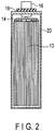
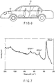
- FIG. 13 is a Raman spectrum according to the surface of the current collector of Example 9.
- a secondary battery includes a positive electrode, a negative electrode, and an electrolyte including a water-containing solvent and a lithium ion.
- the negative electrode includes an aluminum-containing negative electrode current collector and a boehmite-containing cover layer, and the boehmite-containing cover layer is provided on at least a part of a surface of the negative electrode current collector, and has a thickness of 10 nm to 1000 nm.
- a battery pack includes the secondary battery according to the first approach.
- a vehicle is provided.
- the vehicle includes the battery pack according to the second approach.
- a secondary battery includes a positive electrode, a negative electrode, and an electrolyte including a water-containing solvent and a lithium ion.
- the negative electrode includes an aluminum-containing negative electrode current collector and a boehmite-containing cover layer, and the boehmite-containing cover layer is provided on at least a part of a surface of the negative electrode current collector, and has a thickness of 10 nm to 1000 nm.
- a boehmite-containing cover layer is provided on at least a part of a surface of the current collector so that the hydrogen overvoltage can be increased as compared to the case where the cover layer is not formed.
- the boehmite has a structure in which its surface is terminated with a hydroxyl group. It is considered that when hydrogen occurs, a proton is adsorbed to the hydroxyl group and electrons are supplied from the electrode to the proton, thereby generating hydrogen. At this time, it is assumed that any one of the adsorption of the proton to the hydroxyl group, the transfer of electrons from the electrode, and the hydrogen generating reaction is slow from the kinetic viewpoint.
- anions and/or cations in an electrolyte are physically adsorbed to the hydroxyl group on the surface of boehmite.
- anions and/or cations in the electrolyte are adsorbed to the hydroxyl group, the proton is hardly adsorbed to the hydroxyl group. As a result, it is considered that the hydrogen overvoltage is increased.
- boehmite is a chemically stable material such that it functions as a passivation film. It is considered that the boehmite stably exists without causing corrosion and changing its structure in the case where the potential is shifted to a reducing side (in the case where the potential is low).
- a secondary battery can be stably operated by reversibly inserting and extracting lithium. According to the secondary battery, it is possible to achieve an excellent cycle life performance.
- the cover layer may contain hydrated aluminum oxides other than boehmite.
- the cover layer is preferably formed of boehmite.
- the content of boehmite in the cover layer is, for example, 60% by mass or more. It is possible to determine whether the cover layer contains boehmite using micro-Raman spectroscopy analysis described below.
- the boehmite according to the present approach is an alumina monohydrate having an orthorhombic crystal structure with the composition formula AlOOH, and has high crystallinity such that the peak can be clearly observed by micro-Raman spectroscopy analysis. Specifically, a portion where the cover layer is formed on the surface of the negative electrode current collector is measured by micro-Raman spectroscopy analysis using a light source at a wavelength of 532 nm, and the resulting spectrum includes a main peak originated from the Al-O bond of boehmite within a range of from 350 ⁇ 20 cm -1 .
- the spectrum has another peak originated from the structure of boehmite in at least one of the ranges of 495 ⁇ 20 cm -1 , 675 ⁇ 20 cm -1 , and 1090 ⁇ 20 cm -1 . In this case, it is possible to further suppress the generation of hydrogen.
- the cover layer has a thickness of less than 10 nm, it is difficult to sufficiently prevent corrosion in a reduction atmosphere. Thus, the cover layer is broken and the aluminum is exposed, thereby generating hydrogen. As a result, the active material layer may be peeled from the negative electrode current collector.
- the thickness of the cover layer is greater than 1000 nm, the cover layer is too thick, insertion/extraction of lithium through the cover layer hardly occurs, and thus this is not preferred.
- the thickness of the cover layer is preferably from 100 nm to 800 nm, and more preferably from 200 nm to 500 nm.
- the thickness of the cover layer can be measured, for example, as follows.
- the negative electrode is covered with the cover layer using an embedding resin. Then, a sample in which the cross section of the negative electrode can be observed using argon ion milling is produced. The sample is observed using a transmission electron microscope (TEM) at a magnification of 200,000 times.
- TEM transmission electron microscope
- the elemental analysis is performed by Energy Dispersive X-ray (EDX) mapping using Energy Dispersive X-ray Spectrometer (EDS).
- EDX Energy Dispersive X-ray
- EDS Energy Dispersive X-ray Spectrometer
- the thickness of the cover layer can be clearly observed by the analysis. However, it is difficult to observe whether the cover layer contains the boehmite by only the analyses. Therefore, the structure of boehmite is identified by the results of the analyses and the result of the micro-Raman spectroscopy analysis.
- the thickness of the cover layer can be measured by the procedure as described above.
- the analysis using TEM observation in combination with EDX mapping allows for confirmation of a portion where the cover layer is formed on the surface of the negative electrode current collector and a portion where the cover layer is not formed thereon.
- the atomic concentration based on the content of aluminum and the atomic concentration based on the content of oxygen is different from each other, depending on the kinds of compounds such as aluminum metal, boehmite (AlOOH), and alumina (Al 2 O 3 ). Different shades appear on the observation image due to a difference between the atomic concentrations. The observation of the shades allows for confirmation of a portion where the cover layer is formed and a portion where the cover layer is not formed.
- the cover layer has a uniform in-plane thickness.
- a cover layer of boehmite has a uniform in-plane thickness
- the generation of hydrogen caused by exposure of an aluminum matrix can be suppressed, and thus charge/discharge can be reversibly performed.
- the current collector having the cover layer can be appropriately used for a secondary battery obtained by using an electrolyte containing an aqueous solvent. It is possible to observe that the in-plane thickness is uniform, for example, with a scanning electron microscope (SEM).
- the cover layer is formed on the whole surface opposite to the negative electrode active material layer on the surface of the negative electrode current collector.
- the electrolyte is brought into contact with the exposed part, thereby promoting the elution of metal from the current collector and the generation of hydrogen at an early stage.
- the active material layer may be promptly peeled from the current collector.
- the cover layer has few pinholes which are opened in the thickness direction or has no pinholes.
- the coatability of the cover layer is sufficiently high.
- the coatability of the cover layer is high in order to sufficiently suppress the generation of hydrogen from the current collector.
- the cover layer covers the whole surface of the negative electrode current collector. In other words, it is preferable that the cover layer has high coatability.
- the cover layer according to the present approach can be formed by, for example, an anode oxidation method or a boehmite-treatment method to be described below.
- the surface of the current collector is subjected to alkaline degreasing before the production of the layer.
- the degreasing impurities and a naturally oxidized film on the surface of the current collector are removed.
- the current collector is immersed in a solution, thereby suppressing the reattachment of impurities and surface reoxidation.
- the anode oxidation method is a method including: immersing a current collector in an electrolyte solution; and applying a direct current or a high voltage to the current collector as a positive electrode to form an oxidized film on the surface of the current collector.
- the electrolyte solution is, for example, sulfuric acid, oxalic acid, phosphoric acid or chromic acid. It is preferable that the electrolyte solution is one in which dissolved oxygen is sufficiently removed by jetting nitrogen as bubbles in advance. The dissolved oxygen in the electrolyte solution is sufficiently removed, thereby suppressing the pinhole formation caused by oxidation.
- the inert atmosphere may be, for example, a nitrogen atmosphere.
- the film When a film having a thickness of about 15 nm or more is formed by the anode oxidation method, the film is porous. Thus, when a current collector having the film in this state is used for an aqueous secondary battery, a water molecule enters into pores and hydrogen generates from the pores, thereby breaking the cover layer.
- the pore sealing treatment is performed by, for example, immersing the current collector having the above film in boiled pure water. As a result of the pore sealing treatment, boehmite is formed so as to seal the pores.
- the pore sealing treatment may be performed on a film having a thickness of less than 15 nm.
- the current collector When a current collector with a small thickness is used in the anode oxidation method, the current collector may not endure an applied voltage or current, which may lead to breakage.
- the anode oxidation method is performed using a current collector with a large thickness, a film to be formed is not broken and a cover layer with a sufficient thickness is formed on the surface.
- the voltage to be applied As the voltage to be applied is made smaller, the film to be formed tends to become thinner. As the voltage to be applied is made larger, the film to be formed tends to become thicker. In other words, the thickness varies depending on the voltage to be applied.
- the anode oxidation method has difficulty in appropriately forming a cover layer in the case of using a current collector with a thickness of about 100 ⁇ m or less.
- the following boehmite-treatment method may be employed in order to form a cover layer on a relatively thin current collector.
- the boehmite-treatment method may be used to form a cover layer on the current collector with a thickness of 100 ⁇ m or more.
- the boehmite-treatment method is a method including: boiling pure water or an aqueous solution containing a small amount of alkali (e.g., triethanolamine) as an additive; and immersing a current collector therein to form a cover layer.
- alkali e.g., triethanolamine
- the solution functions as a growth agent. Accordingly, the formation of the boehmite layer on the surface of the current collector is promoted, thereby forming a thick cover layer with a sufficient film property.
- the boehmite-treatment method may be used form a cover layer on a relatively thin current collector. It is preferable that the use of the relatively thin current collector increases the volume energy density of a battery.
- the drying process is preferably a natural drying process.
- the drying process is preferably performed at a temperature of 80°C or less for about 1 hour.
- a relatively high temperature e.g., 100°C
- the secondary battery according to the present approach which includes a negative electrode, a positive electrode, and an electrolyte, and a separator may be interposed between the positive electrode and the negative electrode. Further, the secondary battery may further include a container that receives the negative electrode, the positive electrode, and the electrolyte.
- the negative electrode includes a negative electrode current collector and a negative electrode active material layer which is formed on one side or both sides of the negative electrode current collector and contains an active material, a conductive agent, and a binder.
- the cover layer according to the present approach is formed on at least one part of a surface of the negative electrode current collector.
- the cover layer may be formed on at least a part of a negative electrode tab, in addition to at least a part of a surface of the negative electrode current collector.
- the cover layer may be formed on the whole surface of the negative electrode tab.
- the negative electrode current collector is preferably an aluminum foil or an aluminum alloy foil containing at least one kind of elements (one kind or two or more kinds) selected from Mg, Ti, Zn, Mn, Fe, Cu, and Si.
- the aluminum alloy foil may contain only one kind or two or more kinds of these elements.
- the negative electrode current collector may be in another form such as a porous body or mesh.
- the thickness of the aluminum foil or the aluminum alloy foil is, for example, from 10 ⁇ m to 500 ⁇ m. When the above thickness is less than 10 ⁇ m, the possibility that the foil is cut during the production is increased. When the above thickness is greater than 500 ⁇ m, the volume energy density of a battery may be decreased.
- the thickness of the aluminum foil or the aluminum alloy foil is preferably 20 ⁇ m or less and more preferably 15 ⁇ m or less.
- the purity of the aluminum foil is preferably 99% by mass or more, more preferably 99.3% by mass or more, and still more preferably 99.85% by mass or more.
- the aluminum alloy is preferably an alloy containing an element such as magnesium, zinc or silicon. Meanwhile, the content of a transition metal such as iron, copper, nickel or chromium is preferably 1% by mass or less.
- the negative electrode active material layer is formed on the negative electrode current collector, for example, at a density of 20 g/m 2 to 500 g/m 2 .
- density is within the range, charge can be reversibly performed. It is difficult to produce an active material layer having a density of less than 20 g/m 2 by the coating process, which is thus not preferred.
- an Li concentration gradient in an active material layer having a density of greater than 500 g/m 2 increases when lithium is inserted or extracted during the charge/discharge process, thereby reducing battery characteristics.
- the negative electrode active material at least one (one kind or two or more kinds) of titanium-containing oxides such as titanium oxide, lithium titanium oxide, niobium titanium oxide, and sodium niobium titanium oxide may be used.
- the Li insertion potential of the titanium-containing oxide is preferably from 1.2 V (vs. Li/Li + ) to 2.0 V (vs. Li/Li + ).
- the negative electrode active material may contain one kind or two or more kinds of the titanium-containing oxides.
- the titanium oxide examples include a titanium oxide having a monoclinic structure, a titanium oxide having a rutile structure, and a titanium oxide having an anatase structure.
- the composition before charge is TiO 2 and the composition after charge is LixTiO 2 (0 ⁇ x ⁇ 1). Further, the structure of the titanium oxide having a monoclinic structure before charge is TiO 2 (B).
- the lithium titanium oxide examples include a lithium titanium oxide having a spinel structure (e.g., Li 4+x Ti 5 O 12 (-1 ⁇ x ⁇ 3) ; and a lithium titanium oxide having a ramsdellite structure (e.g., Li 2+x Ti 3 O 7 (-1 ⁇ x ⁇ 3), Li 1+x Ti 2 O 4 (0 ⁇ x ⁇ 1), Li 1.1+x Ti 1.8 O 4 (0 ⁇ x ⁇ 1), Li 1.07+x Ti 1.86 O 4 (0 ⁇ x ⁇ 1), and Li x TiO 2 (0 ⁇ x ⁇ 1).
- the lithium titanium oxide may be a lithium-titanium composite oxide into which a dopant is introduced.
- niobium titanium oxide examples include a niobium titanium oxide represented by Li a TiM b Nb 2 ⁇ O 7 ⁇ (0 ⁇ a ⁇ 5, 0 ⁇ b ⁇ 0.3, 0 ⁇ ⁇ ⁇ 0.3, 0 ⁇ ⁇ ⁇ 0.3, where M is at least one kind of elements selected from the group consisting of Fe, V, Mo, and Ta).
- Examples of the sodium niobium titanium oxide include an orthorhombic Na-containing niobium titanium composite oxide represented by Li 2+v Na 2-w M1 x Ti 6-y-z Nb y M2 z O 14+ ⁇ (0 ⁇ v ⁇ 4, 0 ⁇ w ⁇ 2, 0 ⁇ x ⁇ 2, 0 ⁇ y ⁇ 6, 0 ⁇ z ⁇ 3, -0.5 ⁇ ⁇ ⁇ 0.5, M1 includes at least one selected from Cs, K, Sr, Ba, and Ca, and M2 includes at least one selected from Zr, Sn, V, Ta, Mo, W, Fe, Co, Mn, and Al.
- M1 includes at least one selected from Cs, K, Sr, Ba, and Ca
- M2 includes at least one selected from Zr, Sn, V, Ta, Mo, W, Fe, Co, Mn, and Al.
- the negative electrode active material is at least one selected from the group consisting of a spinel type lithium titanate (e.g., Li 4 Ti 5 O 12 ) and an anatase type titanium oxide (e.g., TiO 2 ).
- a spinel type lithium titanate e.g., Li 4 Ti 5 O 12
- an anatase type titanium oxide e.g., TiO 2
- Each of the active materials has a low operating potential.
- the peeling of the active material caused by the generation of hydrogen can be suppressed, whereby charge/discharge can be performed. As a result, it is possible to achieve a high energy density and an excellent cycle life performance.
- the negative electrode contains a negative electrode active material, for example, in the form of particles.
- Negative electrode active material particles may be single primary particles, secondary particles which are aggregates of the primary particles, or a mixture of single primary particles and secondary particles.
- the shape of the particles is not particularly limited, and may be, for example, a spherical shape, an elliptical shape, a flat shape or a fibrous shape.
- the conductive agent is added in order to improve the current collection performance and suppress the contact resistance of the active material to the current collector.
- the conductive agent include carbonaceous substances such as acetylene black, ketjen black, graphite, and coke.
- the conductive agent may be used singly, or in mixture of two or more kinds thereof.
- the binder functions to bond the active material and the conductive agent to be adhered to the current collector.
- the binder for example, at least one selected from the group consisting of polytetrafluoroethylene (PTFE), polyvinylidene fluoride (PVdF), a cellulose-based material (e.g., sodium carboxymethyl cellulose (CMC)), fluorine-based rubber, styrene butadiene rubber, an acrylic resin or its copolymer, polyacrylic acid, and polyacrylonitrile may be used, but is not limited thereto.
- the binder may be used singly, or in mixture of two or more kinds thereof.
- the content of the negative electrode active material is from 60% by weight to 95% by weight
- the content of the negative electrode conductive agent is from 2% by weight to 20% by weight
- the content of the binder is from 2% by weight to 20% by weight.
- the content of the conductive agent is less than 2% by weight, the current collection performance of the negative electrode active material layer is lowered and high current performance of the battery may be reduced.
- the content of the binder is less than 2% by weight, the binding property of the negative electrode active material layer and the negative electrode current collector is lowered and cycle performance may be reduced.
- the content of the conductive agent is preferably 10% by weight or less and the content of the binder is preferably 10% by weight or less.
- the negative electrode is produced by, for example, the following method. First, a negative electrode active material, a conductive agent, and a binder are suspended in a solvent to prepare a slurry. Then, the slurry is applied to one side or both sides of a negative electrode current collector. Here, a cover layer is previously formed on the negative electrode current collector by the above method and the resulting collector is used. The coating film on the negative electrode current collector is dried to form a negative electrode active material layer. Thereafter, the negative electrode current collector and the negative electrode active material layer formed on the negative electrode current collector is pressed. A pellet containing the negative electrode active material, the conductive agent, and the binder may be used for the negative electrode active material layer.
- the positive electrode includes a positive electrode current collector and a positive active material layer which is formed on one side or both sides of the positive electrode current collector and contains an active material, a conductive agent, and a binder.
- the positive electrode current collector is formed of a metal such as stainless steel, Al or Ti.
- the positive electrode current collector may be in the form of porous body or mesh.
- the surface of the current collector may be coated with a dopant.
- the positive electrode current collector is, for example, a Ti foil excellent in corrosion resistance and oxidation resistance.
- a lithium salt (Li 2 SO 4 ) used for the electrolyte described below corrosion does not progress, and thus aluminum (Al) may be used as the positive electrode current collector.
- a positive electrode active material allowing lithium to be inserted thereinto and extracted therefrom may be used.
- the positive electrode may contain one kind or two or more kinds of positive electrode active materials.
- the positive electrode active material include a lithium manganese composite oxide, a lithium nickel composite oxide, a lithium cobalt aluminum composite oxide, a lithium nickel cobalt manganese composite oxide, a spinel type lithium manganese nickel composite oxide, a lithium manganese cobalt composite oxide, a lithium iron oxide, a fluorinated lithium iron sulfate, and a phosphate compound having an olivine crystal structure (e.g., Li x FePO 4 (0 ⁇ x ⁇ 1), Li x MnPO 4 (0 ⁇ x ⁇ 1)).
- the phosphate compound having an olivine crystal structure is excellent in thermal stability.
- Examples of the positive electrode active material by which a high positive electrode potential is obtained will be described below.
- Examples thereof include Li x Mn 2 O 4 (0 ⁇ x ⁇ 1) having a spinel structure, a lithium manganese composite oxide (e.g., Li x MnO 2 (0 ⁇ x ⁇ 1)), a lithium nickel aluminum composite oxide (e.g., Li x Ni 1-y Al y O 2 (0 ⁇ x ⁇ 1, 0 ⁇ y ⁇ 1)), a lithium cobalt composite oxide (e.g., Li x CoO 2 (0 ⁇ x ⁇ 1), a lithium nickel cobalt composite oxide (e.g., Li x Ni 1-y-z CO y Mn z O 2 (0 ⁇ x ⁇ 1, 0 ⁇ y ⁇ 1, 0 ⁇ z ⁇ 1), a lithium manganese cobalt composite oxide (e.g., Li x Mn y CO 1-y O 2 (0 ⁇ x ⁇ 1, 0 ⁇ y
- the positive electrode active material is preferably at least one selected from the group consisting of a lithium cobalt composite oxide, a lithium manganese composite oxide, and a lithium phosphorus oxide having an olivine structure.
- the operating potential of each of the active materials is from 0.2 V (vs. Li/Li + ) to 0.8 V (vs. Li/Li + ), which is a high level. Further, the operating potential of each of the active materials exists near the equilibrium potential for oxygen evolution, thereby stably performing a charge/discharge cycle, which is preferred.
- These positive electrode active materials are used in combination with negative electrode active materials such as the spinel type lithium titanate and the anatase type titanium oxide so that a high battery voltage is obtained.
- the positive electrode contains the positive electrode active material, for example, in the form of particles.
- the positive electrode active material particles may be single primary particles, secondary particles which are aggregates of the primary particles, or a mixture of single primary particles and secondary particles.
- the shape of the particles is not particularly limited, and may be, for example, a spherical shape, an elliptical shape, a flat shape or a fibrous shape.
- the conductive agent is added in order to improve the current collection performance and suppress the contact resistance of the active material to the current collector.
- the conductive agent include carbonaceous substances such as acetylene black, ketjen black, graphite, and coke.
- the conductive agent may be used singly, or in mixture of two or more kinds thereof.
- binder examples include polytetrafluoroethylene (PTFE), polyvinylidene fluoride (PVdF), fluorine-based rubber, ethylene-butadiene rubber, polypropylene (PP), polyethylene (PE), carboxymethylcellulose (CMC), polyimide (PI), and polyacrylimide (PAI).
- PTFE polytetrafluoroethylene
- PVdF polyvinylidene fluoride
- PP polypropylene
- PE polyethylene
- CMC carboxymethylcellulose
- PI polyimide
- PAI polyacrylimide
- the binder may be used singly, or in mixture of two or more kinds thereof.
- the content of the positive electrode active material is from 80% by weight to 95% by weight
- the content of the positive electrode conductive agent is from 3% by weight to 18% by weight
- the content of the binder is from 2% by weight to 7% by weight.
- the electrical conductivity of the positive electrode can be made favorable.
- the compounding ratio of the conductive agent is 18% by weight or less
- the decomposition of the electrolyte on the surface of the conductive agent can be reduced.
- the compounding ratio of the binder is 2% by weight or more, sufficient electrode strength can be attained.
- the compounding ratio of the binder is 7% by weight or more, the insulating part of the electrode can be reduced.
- the positive electrode is produced by, for example, the following method. First, a positive electrode active material, a conductive agent, and a binder are suspended in a solvent to prepare a slurry. Then, the slurry is applied to one side or both sides of a positive electrode current collector. The coating film on the positive electrode current collector is dried to form a positive electrode active material layer. Thereafter, the positive electrode current collector and the positive electrode active material layer formed on the positive electrode current collector is pressed. A pellet containing the positive electrode active material, the conductive agent, and the binder may be used for the positive electrode active material layer.
- the electrolyte contains a water-containing solvent and lithium ions.
- the electrolyte is, for example, a lithium-ion containing solution.
- the electrolyte may be a gel electrolyte obtained by complexing this solution and a polymer material.
- the polymer material include polyvinylidene fluoride (PVdF), polyacrylonitrile (PAN), and polyethylene oxide (PEO).
- the lithium-ion containing solution is prepared by, for example, dissolving a lithium salt in a water-containing solvent.
- the water-containing solvent may be pure water, or may be a mixed solution and/or a mixed solvent of water and a substance other than water.
- the lithium ions contained in the electrolyte are, for example, cations derived from lithium salt.
- the lithium salt include LiCl, LiBr, LiOH, Li 2 SO 4 , LiNO 3 , LiTFSA (lithium trifluoromethane sulfonyl amide), and LiB[(OCO) 2 ] 2 .
- the lithium salt to be used may be one kind or two or more kinds.
- the lithium salt is preferably at least one selected from lithium chloride (LiCl), lithium sulfate (Li 2 SO 4 ), and lithium nitrate (LiNO 3 ).
- the lithium salts are inexpensive because of the easiness of production, thereby producing a battery at low cost.
- the concentration of lithium salt in the electrolyte is preferably 1 M or more. As the concentration of salt is increased, the equilibrium potential in insertion/extraction of lithium becomes a higher potential. Thus, it is possible to further suppress the generation of hydrogen. It is more preferable that the concentration of lithium salt in the electrolyte is from 3 M to a saturated concentration.
- the optimal concentration of salt may be appropriately changed by the combination with the positive electrode.
- the pH of the aqueous solution containing lithium ions may be appropriately changed. From the viewpoint of increasing the hydrogen overvoltage, the pH is preferably on an alkali side. The pH is on an alkali side, whereby the generation of hydrogen can be further suppressed.
- Examples of the method of adjusting the pH of an aqueous solution to the alkali side include a method of adding LiOH.
- the pH of the aqueous solution is preferably within a range of from 2 to 11, and more preferably within a range of from 3 to 9.
- the corrosion of the cover layer can be suppressed, thereby achieving an excellent cycle life performance.
- a separator may be disposed between the positive electrode and the negative electrode.
- the separator include non-woven fabrics, films, and paper.
- examples of a constitution material of the separator include polyolefins such as polyethylene and polypropylene; and cellulose.
- Preferable examples of the separator include cellulose fiber-containing non-woven fabrics and polyolefin fiber-containing porous films.
- the porosity of the separator is preferably 60% or more.
- the fiber diameter is preferably 10 ⁇ m or less. When the fiber diameter is set to 10 ⁇ m or less, the affinity of the electrolyte with the separator is improved, thereby reducing the battery resistance.
- the fiber diameter is more preferably 3 ⁇ m or less.
- a cellulose fiber-containing non-woven fabric having a porosity of 60% or more has an excellent electrolyte impregnation property. Such a separator is used so that a high output performance can be exerted in a range of from low to high temperatures.
- the non-woven fabric does not react with the negative electrode during long-term charge storage, float charge or over-charge, thereby causing no short circuit between the negative electrode and the positive electrode due to the formation of lithium metal dendrites.
- the porosity of the separator is more preferably from 62% to 80%.
- the separator has a thickness of from 20 ⁇ m to 100 ⁇ m and a density of from 0.2 g/cm 3 to 0.9 g/cm 3 .
- the thickness and the density of the separator are within the above ranges respectively, the balance between the mechanical strength and a reduction in resistance of the battery can be adjusted, making it possible to provide a secondary battery which has a high output and is resistant to the development of internal short circuits. Also, a reduction in thermal shrinkage of the separator at high temperatures and a favorable high-temperature storage performance can be attained.
- a metal container As the container that receives the positive electrode, negative electrode, and electrolyte, a metal container, a laminate film container or a resin container which is made of polyethylene or polypropylene may be used.
- a metal container which is made of nickel, iron or stainless steel and has a rectangular or cylindrical shape may be used.
- the plate thickness of each of the resin container and the metal container is preferably from 0.05 mm to 1 mm.
- the plate thickness is more preferably 0.5 mm or less and still more preferably 0.3 mm or less.
- Examples of the laminate film include a multilayer film formed by covering a metal layer with a resin layer.
- Examples of the metal layer include a stainless steel foil, an aluminum foil, and an aluminum alloy foil.
- As the resin layer a polymer such as polypropylene (PP), polyethylene (PE), nylon or polyethylene terephthalate (PET) may be used.
- the thickness of the laminate film is preferably from 0.01 mm to 0.5 mm and more preferably 0.2 mm or less.
- the secondary battery according to the present approach may have various shapes such as a rectangular shape, a cylindrical shape, a flat shape, a thin shape, and a coin shapes. Further, the secondary battery may have a bipolar structure. As a result, a plural of cells connected in series can be produced by one cell, which is advantageous.
- FIG. 1 is a cross-sectional view schematically showing an example of a rectangular secondary battery according to the present approach.
- FIG. 2 is a cross-sectional view along the II-II line of the rectangular secondary battery shown in FIG. 1 .
- An electrode group 13 is received in a rectangular cylindrical metal container 20.
- the electrode group 13 has a structure in which multiple positive electrodes 10, multiple negative electrodes 11, and multiple separators 12 are stacked in the order of the positive electrode 10, the separator 12, the negative electrode 11, and the separator 12.
- the electrode group 13 may have a spirally wound flat structure in which the separator 12 is provided between the positive electrode 10 and the negative electrode 11.
- the separator 12 is disposed on the outermost layer of the electrode group 13 in order to avoid the contact between the electrode and the metal container 20.
- An electrolyte (not shown) is supported by the electrode group 13.
- band-shaped positive electrode tabs 14 are electrically connected to a plural of points of the positive electrode 10 located at the end surface of the electrode group 13.
- band-shaped negative electrode tabs 15 are electrically connected to a plural of points of the negative electrode 11 located at the end surface.
- the positive electrode tabs 14 are electrically connected to a positive electrode lead 16 in a bundled state.
- a positive electrode terminal is constituted of the positive electrode tab 14 (positive electrode inner terminal) and the positive electrode lead 16 (positive electrode external terminal).
- the negative electrode tabs 15 are electrically connected to a negative electrode lead 17 in a bundled state.
- a negative electrode terminal is constituted of the negative electrode tab 15 (negative electrode inner terminal) and the negative electrode lead 17 (negative electrode external terminal).
- a metal sealing plate 21 is secured to an opening part of the metal container 20 by welding.
- the positive electrode lead 16 and the negative electrode lead 17 are respectively drawn externally from each drawing hole formed in the sealing plate 21.
- a positive electrode gasket 18 and a negative electrode gasket 19 are respectively disposed on the inner periphery surface of each drawing hole of the sealing plate 21 in order to avoid short circuits developed by the contact between the positive electrode lead 16 and sealing plate 21, and by the contact between the negative electrode lead 17 and sealing plate 21.
- the airtightness of the rectangular secondary battery can be ensured by disposing the positive electrode gasket 18 and the negative electrode gasket 19.
- a control valve 22 (safety valve) is disposed in the sealing plate 21.
- the control valve 22 to be used is, for example, a return control valve which operates when the internal pressure becomes higher than a set value and which functions as a sealing plug when the internal pressure decreases.
- a non-return valve may be used, where once it is operated, its function as the sealing plug is not recovered.
- the control valve 22 is disposed in the center of the sealing plate 21, and the control valve 22 may be located at the end of the sealing plate 21.
- the control valve 22 may be omitted.
- An injection port 23 is formed in the sealing plate 21.
- An electrolyte is poured through the injection port 23.
- the injection port 23 is closed by a sealing plug 24 after pouring the electrolyte.
- the injection port 23 and the sealing plug 24 may be omitted.
- a battery module may be formed of the secondary batteries according to the present approach.
- Examples of the battery module include those including a plural of unit cells electrically connected in series, in parallel, or in a combination of in series and in parallel; a unit constituted of a plural of unit cells electrically connected in series; those including a unit constituted of a plural of unit cells electrically connected in parallel; and a unit constituted of a plural of unit cells electrically connected in a combination of in series and in parallel.
- the battery module may be received in a cabinet.
- a metal can which is made of an aluminum alloy, iron or stainless steel or a plastic container may be used.
- the thickness of the container is preferably 0.5 mm or more.
- Examples of the form of serial or parallel electrical connection of a plural of secondary batteries include serial or parallel electrical connection of a plural of secondary batteries each having a container, and serial or parallel electrical connection of a plural of secondary electrode groups received in a common cabinet.
- a plural of secondary batteries whose positive and negative electrode terminals are connected by a metal bus bar (e.g., aluminum, nickel, copper).
- a plural of electrode groups are received in one cabinet with electrochemically insulated by a diaphragm, and these electrode groups are electrically connected in series.
- Five to seven batteries are electrically connected in series so that a battery module having favorable voltage compatibility with the lead storage battery can be realized. In order to increase the voltage compatibility with the lead storage battery, it is preferable that five or six unit cells are configured to be connected in series.
- FIG. 3 is a perspective view schematically showing an example of a battery module which includes a plural of the rectangular secondary batteries according to the present approach as a unit cell.
- a battery module 31 includes the rectangular secondary batteries (e.g., batteries 32 1 to 32 5 described in FIGS. 1 and 2 ).
- the positive electrode lead 16 of the battery 32 1 is electrically connected to the negative electrode lead 17 of the battery 32 2 located adjacent to the battery 32 1 through a lead 33.
- the positive electrode lead 16 of the battery 32 2 is electrically connected to the negative electrode lead 17 of the battery 32 3 located adjacent to the battery 32 2 through the lead 33.
- the batteries 32 1 to 32 5 are connected in series.
- the negative electrode includes an aluminum-containing negative electrode current collector and a boehmite-containing cover layer, and the boehmite-containing cover layer is provided on at least a part of a surface of the negative electrode current collector, and has a thickness of 10 nm to 1000 nm.
- the boehmite-containing cover layer is provided on at least a part of a surface of the negative electrode current collector, and has a thickness of 10 nm to 1000 nm.
- a battery pack includes the secondary battery according to the first approach.
- the battery pack may include one or a plural of the secondary batteries (unit cells) according to the first approach as described above.
- the secondary batteries included in the battery pack may be electrically connected in series, in parallel, or in a combination of in series and in parallel.
- the battery pack may further include a protective circuit.
- the protective circuit controls charge/discharge of the secondary battery.
- a circuit included in a device using as the battery pack as a power source e.g., an electronic device or an automobile
- the battery pack may further include an external power distribution terminal.
- the external power distribution terminal outputs a current from the secondary battery to outside and inputs a current to the secondary battery.
- the current is supplied to the outside through the external power distribution terminal.
- charging current including a regenerative energy caused by, for example, power of automobile
- FIG. 4 is an exploded perspective view of a battery pack.
- FIG. 5 is a block diagram showing an electric circuit of the battery pack of FIG. 4 .
- a plurality of unit cells 51 constituted of flat-shaped lithium secondary batteries is stacked in such a manner that a negative electrode terminal 52 and a positive electrode terminal 53 extending out are oriented in the same direction, and bound by an adhesive tape 54 to form a battery module 55. As shown in FIG. 5 , the unit cells 51 are electrically connected in series with each other.
- a printed wiring board 56 is disposed opposing to the side surface of the unit cells 51 from which the negative electrode terminal 52 and the positive electrode terminal 53 are extended. As shown in FIG. 5 , a thermistor 57, a protective circuit 58, and an external power distribution terminal 59 are mounted on the printed wiring board 56. Incidentally, an insulating plate (not shown) is attached to the surface of the printed wiring board 56 which faces the battery module 55, thereby avoiding unnecessary connection of the wiring line of the battery module 55 with the printed wiring board 56.
- a positive electrode lead 60 is connected to the positive electrode terminal 53 which is located at the undermost layer of the battery module 55, and its tip is inserted to and electrically connected to a positive electrode connector 61 of the printed wiring board 56.
- a negative electrode lead 62 is connected to the negative electrode terminal 52 which is located at the uppermost layer of the battery module 55, and its tip is inserted to and electrically connected to a negative electrode connector 63 of the printed wiring board 56.
- These connectors 61 and 63 are connected to the protective circuit 58 via wiring lines 64 and 65 that are formed on the printed wiring board 56.
- the thermistor 57 detects the temperature of each of the unit cells 51 and sends the detection signal to the protective circuit 58.
- the protective circuit 58 can shut down a plus wiring line 66a and a minus wiring line 66b between the protective circuit 58 and the external power distribution terminal 59 under a predetermined condition.
- the predetermined condition refers to, for example, the time at which the temperature detected by the thermistor 57 reaches a predetermined temperature or more. Further, the predetermined condition, refers to the time at which over-charge, over-discharge, and over-current of the unit cells 51 are detected.
- the over-charge detection is performed on each of the unit cells 51 or the battery module 55.
- the battery voltage may be detected or the positive electrode potential or the negative electrode potential may be detected.
- a lithium electrode to be used as a reference electrode is inserted into each of the unit cells 51.
- wiring lines 67 for voltage detection are connected to the unit cells 51 and detection signals are sent to the protective circuit 58 through the wiring lines 67.
- Protective sheets 68 made of rubber or resin are formed on three side surfaces of the battery module 55 except for the side face from which the positive electrode terminal 53 and the negative electrode terminal 52 protrude.
- the battery module 55 is received in a receiving container 69 together with each of the protective sheet 68 and the printed wiring board 56.
- the protective sheets 68 are disposed on both inner surfaces in a long side direction and one of the inner surfaces in a short side direction of the receiving container 69, and the printed wiring board 56 is disposed on the other inner surface in a short side direction.
- the battery module 55 is located in a space surrounded by the protective sheets 68 and the printed wiring board 56.
- a lid 70 is attached to the top of the receiving container 69.
- a heat-shrinkable tape may be used in place of the adhesive tape 54.
- the battery module 55 is bound by placing the protective sheets on both side surfaces of the battery module 55, winding the heat-shrinkable tape and two protective sheets around the battery module 55, and thermally shrinking the heat-shrinkable tape.
- FIGS. 4 and 5 show a form in which the unit cells 51 are connected in series.
- the unit cells may be connected in parallel in order to increase the battery capacity.
- the unit cells may be connected in a combination of in series and in parallel.
- the assembled battery pack may be connected in series or in parallel.
- the battery pack is appropriately changed according to the use.
- the battery pack is used for an application for which charge/discharge at high current is required.
- the battery pack is used as a power source for digital cameras, for vehicles such as two- or four-wheeled hybrid electric vehicle, for two- or four-wheeled electric vehicles, for assisted bicycles, for stationary battery, and for rail way car.
- the battery pack is mounted to a vehicle.
- the battery pack is configured to, for example, recover regenerative energy caused by power of the vehicle.
- the vehicle include two to four-wheeled hybrid electric automobiles, two to four-wheeled electric automobiles, electric assist bicycles, and electric trains.
- the battery pack according to the second approach includes the secondary battery of the first approach so that it is possible to suppress the peeling of the active material layer from the negative electrode current collector and achieve an excellent cycle life performance.
- the second approach it is possible to provide a battery pack suitable as an alternative power source of a lead battery used as a starter power source for vehicle, or a vehicle-mounted secondary battery which is mounted in a hybrid car.
- a vehicle is provided.
- the vehicle includes the battery pack according to the second approach.
- FIG. 6 shows an example of a vehicle which includes the battery pack according to the second approach.
- An automobile 41 shown in FIG. 6 has a battery pack 42 mounted in an engine room in front of a vehicle body.
- the location where the battery pack is mounted in the automobile is not limited to the engine room.
- the battery pack may be mounted at the rear side of the vehicle body of the automobile or under the seat.
- An aluminum plate having a thickness of 200 ⁇ m and a purity of 99.3% was provided.
- the plate was immersed in 5% by weight of an aqueous sodium hydroxide, and subjected to degreasing. Then, the aluminum plate was cleaned and immersed in a sulfuric acid solution in a nitrogen atmosphere, and a voltage was applied from the positive electrode to form an oxide layer on the surface.
- the sulfuric acid solution was used after dissolved oxygen was sufficiently removed by jetting nitrogen as bubbles in advance. After that, the pore sealing treatment was performed by putting the aluminum plate in boiled pure water after cleaning the plate again, and thus a current collector having a boehmite-containing cover layer was produced on the surface.
- FIG. 7 shows the resulting Raman spectrum.
- the Raman spectrum indicates that peaks were observed at positions of 353 cm -1 , 493 cm -1 , and 675 cm -1 . These peak positions correspond to peak intensity positions of the Raman spectrum of boehmite described in FIG. 1 of Journal of Raman Spectroscopy, vol.32, page 745(2011 ). Consequently, it is determined that the boehmite-containing cover layer present on the surface has a sufficient concentration.
- FIG. 8 shows the resulting SEM observation image. From FIG. 8 , it is confirmed that the surface of the cover layer has a network structure and the cover layer uniformly covers the surface of the current collector. Further, it is confirmed that the surface of the cover layer has spots.
- FIG. 9 shows the resulting TEM observation image.
- the cover layer having a contrast lower than that of the aluminum matrix was observed.
- the elemental analysis was performed by EDX mapping.
- the results of the analyses reveal that the cover layer having a thickness of about 450 nm is present on the surface of the current collector.
- a current collector having a cover layer (electrode area: 0.5 cm 2 ) was used as the working electrode, a Pt metal wire was used as the counter electrode, a saturated calomel electrode was used as the reference electrode, and an aqueous solution obtained by dissolving lithium chloride (salt) at a concentration of 3.5 M was used as the electrolyte solution.
- the potential range was in a range of from -1 V to -1.8 V (vs. SCE) and the sweep rate was 10 mV/sec.
- FIG. 10 is a graph showing the measurement results of 10 cycles.
- FIG. 10 also shows the results of cyclic voltammetry of Example 9 and Comparative example 1 as described below.
- the "current" in the graph represents a value of a reduction current caused by the generation of hydrogen. Based on the results of FIG. 10 , an absolute value of the reduction current of the current collector according to Example 1 was 0.002 mA/cm 2 .
- an electrode having the above current collector was produced in the following manner. Lithium titanate (Li 4 Ti 5 O 12 ) was used as an active material, graphite was used as a conductive auxiliary agent, and PTFE was used as a binder.
- the composition in the active material layer had a weight ratio of (the active material: the conductive auxiliary agent: and the binder) 100 : 20 : 10.
- Each powder was added to an N-methyl-2-pyrrolidone solution, which was mixed and stirred to prepare a slurry. The slurry was applied to both sides of the current collector having the cover layer. Then, the solvent was dried and the current collector was rolled to produce an electrode having a density of 20 g/m 2 .
- This electrode was used as the working electrode (electrode area: 0.5 cm 2 ), a Ti metal wire was used as the counter electrode, and an aqueous solution obtained by dissolving lithium chloride (salt) at a concentration of 3.5 M and lithium sulfate (salt) at a concentration of 0.5 M was used as the electrolyte solution, resulting in formation of a single electrode evaluation cell.
- the potential range was in a range of from -0.5 V to -1.8 V (vs. SCE). Charge/discharge was performed at a constant current under the conditions (termination time: 10 minutes, current density: 30 A/m 2 ). The result is shown in FIG. 11 .
- Tables 1 and 2 show the results of Examples 2 to 25 and Comparative examples 1 to 6 described below.
- the "absolute value of the current” represents an absolute value of the current caused by the generation of hydrogen on the surface of the current collector.
- An aluminum foil having a thickness of 15 ⁇ m and a purity of 99.85% was provided.
- the foil was immersed in 5% by weight of an aqueous sodium hydroxide, and subjected to degreasing. Then, the aluminum plate foil was cleaned and immersed in a boiled aqueous solution containing 0.3% by weight of triethanolamine in a nitrogen atmosphere as boehmite treatment. This aqueous solution was used after sufficiently removing dissolved oxygen by jetting nitrogen as bubbles in advance. Thus, a current collector with a boehmite-containing cover layer on its surface was produced.
- Example 2 Micro-Raman spectroscopy analysis, SEM observation, TEM observation, EDX mapping, cyclic voltammetry analysis, and constant current charge/discharge evaluation were performed in the same manner as in Example 1 using the obtained current collector.
- the obtained TEM image indicates that the cover layer having a thickness of about 100 nm is present.
- FIG. 12 is a photograph showing the SEM observation image according to the surface of the current collector produced in Example 9.
- the SEM image shows that the surface has a structure in which fine needle-shaped particles are lined. It is confirmed that the cover layer having such a structure is uniformly formed on the surface of the current collector.
- FIG. 13 is a Raman spectrum according to the surface of the current collector of Example 9.
- the Raman spectrum shows that a peak was observed at least a position of 353 cm -1 . Therefore, it is found that the cover layer contains Al and O elements and has a peak originated from the Al-O bond.
- a current collector having the cover layer was produced in the same manner as in Example 1 except that the anatase type TiO 2 was used as the negative electrode active material.
- Various evaluations were performed in the same manner as in Example 1 using each of the current collectors produced in the examples. These results are shown in Tables 1 and 2.
- a current collector having the cover layer was produced in the same manner as in Example 1 except that the anatase type TiO 2 was used as the negative electrode active material and an aqueous solution containing lithium chloride at a concentration of 9 M was used as the electrolyte solution.
- Various evaluations were performed in the same manner as in Example 1 using each of the current collectors produced in the examples. These results are shown in Tables 1 and 2.
- Examples 2 to 8 and Comparative examples 3 to 4 are examples in which the cover layer was formed by the anode oxidation method. From these results, it is confirmed that when the thickness of the cover layer is increased, whereby the peeling is suppressed during the charge/discharge process and the cycle life is improved. However, like Comparative example 3, when the thickness of the cover layer was greater than 1000 nm, the thickness of the cover layer was too large. Thus, the electrical connection was prevented, whereby charge/discharge could not be performed. Meanwhile, like Comparative example 4, when the thickness of the cover layer was less than 10 nm, the generation of hydrogen on the surface of the current collector was suppressed. However, when an electrode was produced, charge/discharge could not be performed. When the thickness of the cover layer was from 100 nm to 1000 nm, the generation of hydrogen was sufficiently suppressed and both the maximum charge/discharge efficiency and the cycle life were excellent.
- Examples 10 to 14 and Comparative examples 5 to 6 are examples in which the cover layer was formed by the boehmite-treatment method. These results show that the current collector having the cover layer according to the approache can be formed by not only the anode oxidation method but also the boehmite-treatment method.
- the boehmite-treatment method when the thickness of the cover layer was from 100 nm to 1000 nm, the generation of hydrogen was sufficiently suppressed and both the maximum charge/discharge efficiency and the cycle life were excellent. However, the cycle life tended to be inferior to that of the electrode produced by the anode oxidation method.
- the boehmite-treatment method is useful since it is applicable to a relatively thin aluminum foil.
- the concentration of lithium salt was 3 M or more, the maximum charge/discharge efficiency and the cycle life were excellent, compared to when the concentration was less than 3 M. It is confirmed that, particularly, when an electrolyte solution prepared by dissolving lithium chloride at a concentration of 9 M or more is used, the capacity is decreased, however a high charge/discharge efficiency is achieved.
- the electrode produced in the same manner as in Example 1 was used.
- the used positive electrode was produced in the following manner. Lithium manganese (LiMn 2 O 4 ) was used as the positive electrode active material, acetylene black was used as the conductive auxiliary agent, and PVdF was used as the binder.
- the composition in the active material layer had a weight ratio of (the active material: the conductive auxiliary agent: and the binder) 100 : 10 : 10.
- Each powder was added to an N-methyl-2-pyrrolidone solution, which was mixed and stirred to prepare a slurry. The slurry was applied to both sides of a current collector of titanium. Then, the solvent was dried and the current collector was rolled to produce a positive electrode. The density of the electrode was adjusted so that the positive electrode capacity was 1.5 times larger than the negative electrode capacity.
- Table 3 show the results of Examples 27 to 29 described below.
- a secondary battery was produced in the same manner as described in Example 26 except that an aqueous solution obtained by dissolving lithium chloride at a concentration of 9 M was used as the electrolyte solution and the secondary battery was evaluated. The results are shown in Table 3.
- a secondary battery was produced in the same manner as described in Example 26 except that the anatase type TiO 2 was used as the negative electrode active material and the secondary battery was evaluated. The results are shown in Table 3.
- a secondary battery was produced in the same manner as described in Example 28 except that an aqueous solution obtained by dissolving lithium chloride at a concentration of 9 M was used as the electrolyte solution and the secondary battery was evaluated.
- the results are shown in Table 3.
- Example 26 LiMn 2 O 4 Li 4 Ti 5 O 12 LiCl 3.5M + Li 2 SO 4 0.5M 2.45 100
- Example 27 LiMn 2 O 4 Li 4 Ti 5 O 12 LiCl 9M /H 2 O 2.45 200
- the battery produced by using Li 4 Ti 5 O 12 as the negative electrode active material had an average operating voltage of 2.45 V. Further, the battery produced by using the anatase type TiO 2 as the negative electrode active material had an average operating voltage of 2.15 V. These average operating voltages are higher than those of a lead storage battery and a nickel-hydrogen battery. Hence, the secondary batteries according to these examples achieve a high energy density. Further, an excellent cycle life performance was achieved such that the cycle life was 100 times or more. In the case of using the anatase TiO 2 as the negative electrode active material, the equilibrium potential becomes high, whereby the cycle life tends to increase. In the case of using a high concentration of lithium chloride as the electrolyte solution, the charge/discharge efficiency of the negative electrode is high, thereby achieving an excellent cycle life.
- the negative electrode includes an aluminum-containing negative electrode current collector and a boehmite-containing cover layer, and the boehmite-containing cover layer is provided on at least a part of a surface of the negative electrode current collector, and has the thickness of 10 nm to 1000 nm. Accordingly, it is possible to suppress the peeling of the active material layer from the negative electrode current collector. As a result, an excellent cycle life performance can be achieved.
Abstract
Description
- The present disclosure relates to a secondary battery, a battery pack, and a vehicle.
- Recently, a battery formed using a nonaqueous solvent such as a lithium ion secondary battery has been developed as a battery having a high energy density. The lithium ion secondary battery is excellent in energy density and cycle characteristics compared to a lead storage battery and a nickel hydrogen secondary battery, and is expected to be used as a power source for large electricity storage, such as a power source for vehicles such as hybrid vehicles and electric vehicles. From the viewpoint of providing a large potential window, a nonaqueous solvent such as ethylene carbonate, diethyl carbonate or propylene carbonate is used as an electrolyte solution of the lithium ion secondary battery. Since these solvents are flammable, there are safety problems. If each of the solvents can be replaced with an aqueous electrolyte solution, it is possible to basically solve the problems. The aqueous electrolyte solution is inexpensive, compared to a nonaqueous electrolyte solution. Further, it is not necessary that a production process is performed in an inert atmosphere. Therefore, the nonaqueous electrolyte solution is replaced with the aqueous electrolyte solution, whereby a large cost reduction is expected.
- However, there is a large problem in the use of the aqueous electrolyte solution for the lithium ion secondary battery. The problem is that the theoretical decomposition voltage calculated by the chemical equilibrium of water is 1.23 V, and thus a battery is configured to have a design voltage which is greater than the above voltage, whereby oxygen generates in a positive electrode and hydrogen generates in a negative electrode. In order to solve the problem, the oxygen overvoltage is increased at the oxidation side (positive electrode side) and the hydrogen overvoltage is increased at the reduction side (negative electrode side). From the viewpoint of kinetics, it is necessary to improve the design of the battery.
- In the lithium ion secondary battery formed by using an aqueous solution, the charge/discharge process of the positive electrode is relatively easy. There are many reported examples of positive electrode active materials such as LiCoO2, LiMn2O4, and LiFePO4. Meanwhile, there are reported examples of negative electrode active materials having a lithium insertion/extraction potential of about - 0.5 V (vs. SHE), such as LiTi2 (PO4)3, TiP2O7, and VO2(B). However, there are few reported examples of active materials which operate at a potential lower than the above potential. This is due to the fact that it is difficult to charge/discharge because the generation of hydrogen proceeds in the negative electrode. Even when a battery is formed using each of the above-described active materials as the negative electrode active material, the average operating potential is less than 2 V. In this case, it is difficult to allow the battery to have a high energy density. Currently, there is no aqueous secondary battery which has an energy density greater than that of the lead storage battery or the nickel hydrogen secondary battery. For example, if a lithium ion secondary battery using an aqueous solution can be formed by using TiO2 or Li4Ti5O12 having a lower lithium insertion/extraction potential, it is possible to achieve a high energy density.
-
-
FIG. 1 is a cross-sectional view schematically showing an example of a rectangular secondary battery according to a first approach; -
FIG. 2 is a cross-sectional view along the II-II line of the rectangular secondary battery shown inFIG. 1 ; -
FIG. 3 is a perspective view schematically showing an example of a battery module according to the first approach; -
FIG. 4 is an exploded perspective view schematically showing an example of a battery pack according to a second approach; -
FIG. 5 is a block diagram showing an electric circuit of the battery pack ofFIG. 4 ; -
FIG. 6 is a cross-sectional view schematically showing an example of a vehicle according to a third approach; -
FIG. 7 is a Raman spectrum according to a surface of a current collector of Example 1; -
FIG. 8 is a photograph showing an SEM observation image according to the surface of the current collector of Example 1; -
FIG. 9 is a photograph showing a TEM observation image according to a cross-section of the current collector of Example 1; -
FIG. 10 is a graph showing the results of cyclic voltammetry according to Examples and Comparative example 1; -
FIG. 11 is a graph showing a constant current charge/discharge curve according to Example 1; -
FIG. 12 is a photograph showing an SEM observation image according to a surface of a current collector of -
FIG. 13 is a Raman spectrum according to the surface of the current collector of Example 9. - According to a first approach, a secondary battery is provided. The secondary battery includes a positive electrode, a negative electrode, and an electrolyte including a water-containing solvent and a lithium ion. The negative electrode includes an aluminum-containing negative electrode current collector and a boehmite-containing cover layer, and the boehmite-containing cover layer is provided on at least a part of a surface of the negative electrode current collector, and has a thickness of 10 nm to 1000 nm.
- According to a second approach, a battery pack is provided. The battery pack includes the secondary battery according to the first approach.
- According to a third approach, a vehicle is provided. The vehicle includes the battery pack according to the second approach.
- According to at least one of the approaches described above, it is possible to achieve an excellent cycle life performance.
- According to a first approach, a secondary battery is provided. The secondary battery includes a positive electrode, a negative electrode, and an electrolyte including a water-containing solvent and a lithium ion. The negative electrode includes an aluminum-containing negative electrode current collector and a boehmite-containing cover layer, and the boehmite-containing cover layer is provided on at least a part of a surface of the negative electrode current collector, and has a thickness of 10 nm to 1000 nm.
- A boehmite-containing cover layer is provided on at least a part of a surface of the current collector so that the hydrogen overvoltage can be increased as compared to the case where the cover layer is not formed. Although the reason is not certain, the present inventors consider as follows. The boehmite has a structure in which its surface is terminated with a hydroxyl group. It is considered that when hydrogen occurs, a proton is adsorbed to the hydroxyl group and electrons are supplied from the electrode to the proton, thereby generating hydrogen. At this time, it is assumed that any one of the adsorption of the proton to the hydroxyl group, the transfer of electrons from the electrode, and the hydrogen generating reaction is slow from the kinetic viewpoint. In addition, it is assumed that anions and/or cations in an electrolyte are physically adsorbed to the hydroxyl group on the surface of boehmite. When anions and/or cations in the electrolyte are adsorbed to the hydroxyl group, the proton is hardly adsorbed to the hydroxyl group. As a result, it is considered that the hydrogen overvoltage is increased.
- Furthermore, boehmite is a chemically stable material such that it functions as a passivation film. It is considered that the boehmite stably exists without causing corrosion and changing its structure in the case where the potential is shifted to a reducing side (in the case where the potential is low).
- When the hydrogen overvoltage is increased, it is possible to suppress the generation of hydrogen from the current collector and the elution of metal ions from the current collector caused thereby in the case of using a negative electrode material having a low potential (such as a titanium oxide or a lithium titanium oxide) as the negative electrode active material. Therefore, it is possible to prevent the peeling of the active material layer from the negative electrode current collector. That is, a secondary battery can be stably operated by reversibly inserting and extracting lithium. According to the secondary battery, it is possible to achieve an excellent cycle life performance.
- The cover layer may contain hydrated aluminum oxides other than boehmite. The cover layer is preferably formed of boehmite. The content of boehmite in the cover layer is, for example, 60% by mass or more. It is possible to determine whether the cover layer contains boehmite using micro-Raman spectroscopy analysis described below.
- The boehmite according to the present approach is an alumina monohydrate having an orthorhombic crystal structure with the composition formula AlOOH, and has high crystallinity such that the peak can be clearly observed by micro-Raman spectroscopy analysis. Specifically, a portion where the cover layer is formed on the surface of the negative electrode current collector is measured by micro-Raman spectroscopy analysis using a light source at a wavelength of 532 nm, and the resulting spectrum includes a main peak originated from the Al-O bond of boehmite within a range of from 350±20 cm-1. It is preferable that the spectrum has another peak originated from the structure of boehmite in at least one of the ranges of 495±20 cm-1, 675±20 cm-1, and 1090±20 cm-1. In this case, it is possible to further suppress the generation of hydrogen.
- When the cover layer has a thickness of less than 10 nm, it is difficult to sufficiently prevent corrosion in a reduction atmosphere. Thus, the cover layer is broken and the aluminum is exposed, thereby generating hydrogen. As a result, the active material layer may be peeled from the negative electrode current collector. When the thickness of the cover layer is greater than 1000 nm, the cover layer is too thick, insertion/extraction of lithium through the cover layer hardly occurs, and thus this is not preferred. The thickness of the cover layer is preferably from 100 nm to 800 nm, and more preferably from 200 nm to 500 nm.
- The thickness of the cover layer can be measured, for example, as follows.
- First, the negative electrode is covered with the cover layer using an embedding resin. Then, a sample in which the cross section of the negative electrode can be observed using argon ion milling is produced. The sample is observed using a transmission electron microscope (TEM) at a magnification of 200,000 times. In addition, the elemental analysis is performed by Energy Dispersive X-ray (EDX) mapping using Energy Dispersive X-ray Spectrometer (EDS). The thickness of the cover layer can be clearly observed by the analysis. However, it is difficult to observe whether the cover layer contains the boehmite by only the analyses. Therefore, the structure of boehmite is identified by the results of the analyses and the result of the micro-Raman spectroscopy analysis. The thickness of the cover layer can be measured by the procedure as described above.
- Further, the analysis using TEM observation in combination with EDX mapping allows for confirmation of a portion where the cover layer is formed on the surface of the negative electrode current collector and a portion where the cover layer is not formed thereon. The atomic concentration based on the content of aluminum and the atomic concentration based on the content of oxygen is different from each other, depending on the kinds of compounds such as aluminum metal, boehmite (AlOOH), and alumina (Al2O3). Different shades appear on the observation image due to a difference between the atomic concentrations. The observation of the shades allows for confirmation of a portion where the cover layer is formed and a portion where the cover layer is not formed.
- It is preferable that the cover layer has a uniform in-plane thickness. For example, in the case where a cover layer of boehmite has a uniform in-plane thickness, the generation of hydrogen caused by exposure of an aluminum matrix can be suppressed, and thus charge/discharge can be reversibly performed. As a result, the current collector having the cover layer can be appropriately used for a secondary battery obtained by using an electrolyte containing an aqueous solvent. It is possible to observe that the in-plane thickness is uniform, for example, with a scanning electron microscope (SEM).
- It is preferable that the cover layer is formed on the whole surface opposite to the negative electrode active material layer on the surface of the negative electrode current collector. When there is an exposed part of the current collector in the negative electrode, the electrolyte is brought into contact with the exposed part, thereby promoting the elution of metal from the current collector and the generation of hydrogen at an early stage. As a result, the active material layer may be promptly peeled from the current collector.
- It is preferable that the cover layer has few pinholes which are opened in the thickness direction or has no pinholes. As described above, in the case where the cover layer is formed on the whole surface opposite to the negative electrode active material layer on the surface of the negative electrode current collector and has few pinholes, the coatability of the cover layer is sufficiently high. In the secondary battery obtained by using an electrolyte containing an aqueous solvent, it is preferable that the coatability of the cover layer is high in order to sufficiently suppress the generation of hydrogen from the current collector. The cover layer produced by the production method described below has a uniform in-plane thickness and high coatability.
- It is preferable that the cover layer covers the whole surface of the negative electrode current collector. In other words, it is preferable that the cover layer has high coatability.
- The cover layer according to the present approach can be formed by, for example, an anode oxidation method or a boehmite-treatment method to be described below.
- In the case of forming the cover layer by either of the above methods, the surface of the current collector is subjected to alkaline degreasing before the production of the layer. As a result of the degreasing, impurities and a naturally oxidized film on the surface of the current collector are removed. Thus, in the anode oxidation method or the boehmite-treatment method, the current collector is immersed in a solution, thereby suppressing the reattachment of impurities and surface reoxidation.
- The anode oxidation method is a method including: immersing a current collector in an electrolyte solution; and applying a direct current or a high voltage to the current collector as a positive electrode to form an oxidized film on the surface of the current collector.
- The electrolyte solution is, for example, sulfuric acid, oxalic acid, phosphoric acid or chromic acid. It is preferable that the electrolyte solution is one in which dissolved oxygen is sufficiently removed by jetting nitrogen as bubbles in advance. The dissolved oxygen in the electrolyte solution is sufficiently removed, thereby suppressing the pinhole formation caused by oxidation.
- It is preferable to perform an anode oxidation treatment in an inert atmosphere in order to prevent oxygen from being mixed with the electrolyte solution during the treatment. The inert atmosphere may be, for example, a nitrogen atmosphere.
- When a film having a thickness of about 15 nm or more is formed by the anode oxidation method, the film is porous. Thus, when a current collector having the film in this state is used for an aqueous secondary battery, a water molecule enters into pores and hydrogen generates from the pores, thereby breaking the cover layer.
- Therefore, it is preferable to perform a pore sealing treatment. The pore sealing treatment is performed by, for example, immersing the current collector having the above film in boiled pure water. As a result of the pore sealing treatment, boehmite is formed so as to seal the pores. The pore sealing treatment may be performed on a film having a thickness of less than 15 nm.
- When a current collector with a small thickness is used in the anode oxidation method, the current collector may not endure an applied voltage or current, which may lead to breakage. When the anode oxidation method is performed using a current collector with a large thickness, a film to be formed is not broken and a cover layer with a sufficient thickness is formed on the surface. As the voltage to be applied is made smaller, the film to be formed tends to become thinner. As the voltage to be applied is made larger, the film to be formed tends to become thicker. In other words, the thickness varies depending on the voltage to be applied.
- The anode oxidation method has difficulty in appropriately forming a cover layer in the case of using a current collector with a thickness of about 100 µm or less. As described above, in order to form a cover layer on a relatively thin current collector, the following boehmite-treatment method may be employed. In this regard, the boehmite-treatment method may be used to form a cover layer on the current collector with a thickness of 100 µm or more.
- The boehmite-treatment method is a method including: boiling pure water or an aqueous solution containing a small amount of alkali (e.g., triethanolamine) as an additive; and immersing a current collector therein to form a cover layer. When the boiled solution contains alkali, the solution functions as a growth agent. Accordingly, the formation of the boehmite layer on the surface of the current collector is promoted, thereby forming a thick cover layer with a sufficient film property.
- As described above, the boehmite-treatment method may be used form a cover layer on a relatively thin current collector. It is preferable that the use of the relatively thin current collector increases the volume energy density of a battery.
- In the boehmite-treatment method, when the time immersing the current collector in the boiled solution is shortened, the film to be formed tends to become thinner. When the time immersing the current collector in the boiled solution is lengthen, the film to be formed tends to become thicker.
- In the case of using either the anode oxidation method or the boehmite-treatment method, after forming the cover layer, the drying process is preferably a natural drying process. For example, the drying process is preferably performed at a temperature of 80°C or less for about 1 hour. When the drying process is performed at a relatively high temperature (e.g., 100°C), dry spots form on the cover layer, thereby reducing the coatability.
- As described above, the secondary battery according to the present approach which includes a negative electrode, a positive electrode, and an electrolyte, and a separator may be interposed between the positive electrode and the negative electrode. Further, the secondary battery may further include a container that receives the negative electrode, the positive electrode, and the electrolyte.
- Hereinafter, the negative electrode, the positive electrode, the electrolyte, the separator, and the container will be described.
- The negative electrode includes a negative electrode current collector and a negative electrode active material layer which is formed on one side or both sides of the negative electrode current collector and contains an active material, a conductive agent, and a binder. The cover layer according to the present approach is formed on at least one part of a surface of the negative electrode current collector. The cover layer may be formed on at least a part of a negative electrode tab, in addition to at least a part of a surface of the negative electrode current collector. The cover layer may be formed on the whole surface of the negative electrode tab.
- The negative electrode current collector is preferably an aluminum foil or an aluminum alloy foil containing at least one kind of elements (one kind or two or more kinds) selected from Mg, Ti, Zn, Mn, Fe, Cu, and Si. The aluminum alloy foil may contain only one kind or two or more kinds of these elements. The negative electrode current collector may be in another form such as a porous body or mesh.
- The thickness of the aluminum foil or the aluminum alloy foil is, for example, from 10 µm to 500 µm. When the above thickness is less than 10 µm, the possibility that the foil is cut during the production is increased. When the above thickness is greater than 500 µm, the volume energy density of a battery may be decreased. The thickness of the aluminum foil or the aluminum alloy foil is preferably 20 µm or less and more preferably 15 µm or less.
- The purity of the aluminum foil is preferably 99% by mass or more, more preferably 99.3% by mass or more, and still more preferably 99.85% by mass or more.
- The aluminum alloy is preferably an alloy containing an element such as magnesium, zinc or silicon. Meanwhile, the content of a transition metal such as iron, copper, nickel or chromium is preferably 1% by mass or less.
- The negative electrode active material layer is formed on the negative electrode current collector, for example, at a density of 20 g/m2 to 500 g/m2. When the density is within the range, charge can be reversibly performed. It is difficult to produce an active material layer having a density of less than 20 g/m2 by the coating process, which is thus not preferred. Further, an Li concentration gradient in an active material layer having a density of greater than 500 g/m2 increases when lithium is inserted or extracted during the charge/discharge process, thereby reducing battery characteristics.
- As the negative electrode active material, at least one (one kind or two or more kinds) of titanium-containing oxides such as titanium oxide, lithium titanium oxide, niobium titanium oxide, and sodium niobium titanium oxide may be used. The Li insertion potential of the titanium-containing oxide is preferably from 1.2 V (vs. Li/Li+) to 2.0 V (vs. Li/Li+). The negative electrode active material may contain one kind or two or more kinds of the titanium-containing oxides.
- Examples of the titanium oxide include a titanium oxide having a monoclinic structure, a titanium oxide having a rutile structure, and a titanium oxide having an anatase structure. As for the titanium oxide having each of the crystal structures, the composition before charge is TiO2 and the composition after charge is LixTiO2 (0 ≤ x ≤ 1). Further, the structure of the titanium oxide having a monoclinic structure before charge is TiO2 (B).
- Examples of the lithium titanium oxide include a lithium titanium oxide having a spinel structure (e.g., Li4+xTi5O12 (-1 ≤ x ≤ 3) ; and a lithium titanium oxide having a ramsdellite structure (e.g., Li2+xTi3O7 (-1 ≤ x ≤ 3), Li1+xTi2O4 (0 ≤ x ≤ 1), Li1.1+xTi1.8O4 (0 ≤ x ≤1), Li1.07+xTi1.86O4 (0 ≤ x ≤ 1), and LixTiO2 (0 < x ≤ 1). The lithium titanium oxide may be a lithium-titanium composite oxide into which a dopant is introduced.
- Examples of the niobium titanium oxide include a niobium titanium oxide represented by LiaTiMbNb2±βO7±σ (0 ≤ a ≤ 5, 0 ≤ b ≤ 0.3, 0 ≤ β ≤ 0.3, 0 ≤ σ ≤ 0.3, where M is at least one kind of elements selected from the group consisting of Fe, V, Mo, and Ta).
- Examples of the sodium niobium titanium oxide include an orthorhombic Na-containing niobium titanium composite oxide represented by Li2+vNa2-wM1xTi6-y-zNbyM2zO14+δ (0 ≤ v ≤ 4, 0 < w < 2, 0 ≤ x < 2, 0 < y < 6, 0 ≤ z < 3, -0.5 ≤ δ ≤ 0.5, M1 includes at least one selected from Cs, K, Sr, Ba, and Ca, and M2 includes at least one selected from Zr, Sn, V, Ta, Mo, W, Fe, Co, Mn, and Al.
- It is preferable that the negative electrode active material is at least one selected from the group consisting of a spinel type lithium titanate (e.g., Li4Ti5O12) and an anatase type titanium oxide (e.g., TiO2). Each of the active materials has a low operating potential. However, in the case of using the negative electrode which includes the negative electrode current collector having the cover layer according to the present approach, the peeling of the active material caused by the generation of hydrogen can be suppressed, whereby charge/discharge can be performed. As a result, it is possible to achieve a high energy density and an excellent cycle life performance.
- The negative electrode contains a negative electrode active material, for example, in the form of particles. Negative electrode active material particles may be single primary particles, secondary particles which are aggregates of the primary particles, or a mixture of single primary particles and secondary particles. The shape of the particles is not particularly limited, and may be, for example, a spherical shape, an elliptical shape, a flat shape or a fibrous shape.
- If necessary, the conductive agent is added in order to improve the current collection performance and suppress the contact resistance of the active material to the current collector. Examples of the conductive agent include carbonaceous substances such as acetylene black, ketjen black, graphite, and coke. The conductive agent may be used singly, or in mixture of two or more kinds thereof.
- The binder functions to bond the active material and the conductive agent to be adhered to the current collector. As the binder, for example, at least one selected from the group consisting of polytetrafluoroethylene (PTFE), polyvinylidene fluoride (PVdF), a cellulose-based material (e.g., sodium carboxymethyl cellulose (CMC)), fluorine-based rubber, styrene butadiene rubber, an acrylic resin or its copolymer, polyacrylic acid, and polyacrylonitrile may be used, but is not limited thereto. The binder may be used singly, or in mixture of two or more kinds thereof.
- As for the compounding ratio of the negative electrode active material, the conductive agent, and the binder in the negative electrode active material layer, it is preferable that the content of the negative electrode active material is from 60% by weight to 95% by weight, the content of the negative electrode conductive agent is from 2% by weight to 20% by weight, the content of the binder is from 2% by weight to 20% by weight. When the content of the conductive agent is less than 2% by weight, the current collection performance of the negative electrode active material layer is lowered and high current performance of the battery may be reduced. When the content of the binder is less than 2% by weight, the binding property of the negative electrode active material layer and the negative electrode current collector is lowered and cycle performance may be reduced. Meanwhile, from the viewpoint of performance of high capacity, the content of the conductive agent is preferably 10% by weight or less and the content of the binder is preferably 10% by weight or less.
- The negative electrode is produced by, for example, the following method. First, a negative electrode active material, a conductive agent, and a binder are suspended in a solvent to prepare a slurry. Then, the slurry is applied to one side or both sides of a negative electrode current collector. Here, a cover layer is previously formed on the negative electrode current collector by the above method and the resulting collector is used. The coating film on the negative electrode current collector is dried to form a negative electrode active material layer. Thereafter, the negative electrode current collector and the negative electrode active material layer formed on the negative electrode current collector is pressed. A pellet containing the negative electrode active material, the conductive agent, and the binder may be used for the negative electrode active material layer.
- The positive electrode includes a positive electrode current collector and a positive active material layer which is formed on one side or both sides of the positive electrode current collector and contains an active material, a conductive agent, and a binder.
- The positive electrode current collector is formed of a metal such as stainless steel, Al or Ti. The positive electrode current collector may be in the form of porous body or mesh. In order to prevent corrosion of the current collector due to the reaction of the current collector with the electrolyte solution, the surface of the current collector may be coated with a dopant. Preferably, the positive electrode current collector is, for example, a Ti foil excellent in corrosion resistance and oxidation resistance. In the case of using a lithium salt (Li2SO4) used for the electrolyte described below, corrosion does not progress, and thus aluminum (Al) may be used as the positive electrode current collector.
- A positive electrode active material allowing lithium to be inserted thereinto and extracted therefrom may be used. The positive electrode may contain one kind or two or more kinds of positive electrode active materials. Examples of the positive electrode active material include a lithium manganese composite oxide, a lithium nickel composite oxide, a lithium cobalt aluminum composite oxide, a lithium nickel cobalt manganese composite oxide, a spinel type lithium manganese nickel composite oxide, a lithium manganese cobalt composite oxide, a lithium iron oxide, a fluorinated lithium iron sulfate, and a phosphate compound having an olivine crystal structure (e.g., LixFePO4 (0 ≤ x ≤ 1), LixMnPO4 (0 ≤ x ≤ 1)). The phosphate compound having an olivine crystal structure is excellent in thermal stability.
- Examples of the positive electrode active material by which a high positive electrode potential is obtained will be described below. Examples thereof include LixMn2O4 (0 < x ≤ 1) having a spinel structure, a lithium manganese composite oxide (e.g., LixMnO2 (0 < x ≤ 1)), a lithium nickel aluminum composite oxide (e.g., LixNi1-yAlyO2 (0 < x ≤ 1, 0 < y ≤ 1)), a lithium cobalt composite oxide (e.g., LixCoO2 (0 < x ≤ 1), a lithium nickel cobalt composite oxide (e.g., LixNi1-y-zCOyMnzO2 (0 < x ≤ 1, 0 < y ≤1, 0 ≤ z ≤ 1), a lithium manganese cobalt composite oxide (e.g., LixMnyCO1-yO2 (0 < x ≤ 1, 0 < y ≤ 1), a spinel type lithium manganese nickel composite oxide (e.g., LixMn2-yNiyO4 (0< x ≤ 1, 0< y < 2)), a lithium phosphorus oxide having an olivine structure (e.g., LixFePO4 (0 < x ≤ 1), LixFe1-yMnyPO4 (0 < x ≤ 1, 0 ≤ y ≤ 1), LixCoPO4 (0 < x ≤ 1)), and a fluorinated iron sulfate (e.g., LixFeSO4F (0 < x ≤ 1)).
- The positive electrode active material is preferably at least one selected from the group consisting of a lithium cobalt composite oxide, a lithium manganese composite oxide, and a lithium phosphorus oxide having an olivine structure. The operating potential of each of the active materials is from 0.2 V (vs. Li/Li+) to 0.8 V (vs. Li/Li+), which is a high level. Further, the operating potential of each of the active materials exists near the equilibrium potential for oxygen evolution, thereby stably performing a charge/discharge cycle, which is preferred. These positive electrode active materials are used in combination with negative electrode active materials such as the spinel type lithium titanate and the anatase type titanium oxide so that a high battery voltage is obtained.
- The positive electrode contains the positive electrode active material, for example, in the form of particles. The positive electrode active material particles may be single primary particles, secondary particles which are aggregates of the primary particles, or a mixture of single primary particles and secondary particles. The shape of the particles is not particularly limited, and may be, for example, a spherical shape, an elliptical shape, a flat shape or a fibrous shape.
- If necessary, the conductive agent is added in order to improve the current collection performance and suppress the contact resistance of the active material to the current collector. Examples of the conductive agent include carbonaceous substances such as acetylene black, ketjen black, graphite, and coke. The conductive agent may be used singly, or in mixture of two or more kinds thereof.
- Examples of the binder include polytetrafluoroethylene (PTFE), polyvinylidene fluoride (PVdF), fluorine-based rubber, ethylene-butadiene rubber, polypropylene (PP), polyethylene (PE), carboxymethylcellulose (CMC), polyimide (PI), and polyacrylimide (PAI). The binder may be used singly, or in mixture of two or more kinds thereof.
- As for the compounding ratio of the positive electrode active material, the conductive agent, and the binder in the positive electrode active material layer, it is preferable that the content of the positive electrode active material is from 80% by weight to 95% by weight, the content of the positive electrode conductive agent is from 3% by weight to 18% by weight, the content of the binder is from 2% by weight to 7% by weight. When the compounding ratio of the conductive agent is 3% by weight or more, the electrical conductivity of the positive electrode can be made favorable. When the compounding ratio of the conductive agent is 18% by weight or less, the decomposition of the electrolyte on the surface of the conductive agent can be reduced. When the compounding ratio of the binder is 2% by weight or more, sufficient electrode strength can be attained. When the compounding ratio of the binder is 7% by weight or more, the insulating part of the electrode can be reduced.
- The positive electrode is produced by, for example, the following method. First, a positive electrode active material, a conductive agent, and a binder are suspended in a solvent to prepare a slurry. Then, the slurry is applied to one side or both sides of a positive electrode current collector. The coating film on the positive electrode current collector is dried to form a positive electrode active material layer. Thereafter, the positive electrode current collector and the positive electrode active material layer formed on the positive electrode current collector is pressed. A pellet containing the positive electrode active material, the conductive agent, and the binder may be used for the positive electrode active material layer.
- The electrolyte contains a water-containing solvent and lithium ions. The electrolyte is, for example, a lithium-ion containing solution. The electrolyte may be a gel electrolyte obtained by complexing this solution and a polymer material. Examples of the polymer material include polyvinylidene fluoride (PVdF), polyacrylonitrile (PAN), and polyethylene oxide (PEO).
- The lithium-ion containing solution is prepared by, for example, dissolving a lithium salt in a water-containing solvent. The water-containing solvent may be pure water, or may be a mixed solution and/or a mixed solvent of water and a substance other than water.
- The lithium ions contained in the electrolyte are, for example, cations derived from lithium salt. Examples of the lithium salt include LiCl, LiBr, LiOH, Li2SO4, LiNO3, LiTFSA (lithium trifluoromethane sulfonyl amide), and LiB[(OCO)2]2. The lithium salt to be used may be one kind or two or more kinds.
- The lithium salt is preferably at least one selected from lithium chloride (LiCl), lithium sulfate (Li2SO4), and lithium nitrate (LiNO3). The lithium salts are inexpensive because of the easiness of production, thereby producing a battery at low cost.
- The concentration of lithium salt in the electrolyte is preferably 1 M or more. As the concentration of salt is increased, the equilibrium potential in insertion/extraction of lithium becomes a higher potential. Thus, it is possible to further suppress the generation of hydrogen. It is more preferable that the concentration of lithium salt in the electrolyte is from 3 M to a saturated concentration. The optimal concentration of salt may be appropriately changed by the combination with the positive electrode. In the case where the concentration of lithium salt is relatively high, the pH of the aqueous solution containing lithium ions may be appropriately changed. From the viewpoint of increasing the hydrogen overvoltage, the pH is preferably on an alkali side. The pH is on an alkali side, whereby the generation of hydrogen can be further suppressed. Examples of the method of adjusting the pH of an aqueous solution to the alkali side include a method of adding LiOH. However, when the pH is greater than 12, the corrosion of the current collector progresses, and thus this is not preferred. The pH of the aqueous solution is preferably within a range of from 2 to 11, and more preferably within a range of from 3 to 9. When the pH is within the above range, the corrosion of the cover layer can be suppressed, thereby achieving an excellent cycle life performance.
- A separator may be disposed between the positive electrode and the negative electrode. Examples of the separator include non-woven fabrics, films, and paper. Examples of a constitution material of the separator include polyolefins such as polyethylene and polypropylene; and cellulose. Preferable examples of the separator include cellulose fiber-containing non-woven fabrics and polyolefin fiber-containing porous films.
- The porosity of the separator is preferably 60% or more. The fiber diameter is preferably 10 µm or less. When the fiber diameter is set to 10 µm or less, the affinity of the electrolyte with the separator is improved, thereby reducing the battery resistance. The fiber diameter is more preferably 3 µm or less. A cellulose fiber-containing non-woven fabric having a porosity of 60% or more has an excellent electrolyte impregnation property. Such a separator is used so that a high output performance can be exerted in a range of from low to high temperatures. Further, the non-woven fabric does not react with the negative electrode during long-term charge storage, float charge or over-charge, thereby causing no short circuit between the negative electrode and the positive electrode due to the formation of lithium metal dendrites. The porosity of the separator is more preferably from 62% to 80%.
- It is preferable that the separator has a thickness of from 20 µm to 100 µm and a density of from 0.2 g/cm3 to 0.9 g/cm3. When the thickness and the density of the separator are within the above ranges respectively, the balance between the mechanical strength and a reduction in resistance of the battery can be adjusted, making it possible to provide a secondary battery which has a high output and is resistant to the development of internal short circuits. Also, a reduction in thermal shrinkage of the separator at high temperatures and a favorable high-temperature storage performance can be attained.
- As the container that receives the positive electrode, negative electrode, and electrolyte, a metal container, a laminate film container or a resin container which is made of polyethylene or polypropylene may be used.
- As the metal container, a metal can which is made of nickel, iron or stainless steel and has a rectangular or cylindrical shape may be used.
- The plate thickness of each of the resin container and the metal container is preferably from 0.05 mm to 1 mm. The plate thickness is more preferably 0.5 mm or less and still more preferably 0.3 mm or less.
- Examples of the laminate film include a multilayer film formed by covering a metal layer with a resin layer. Examples of the metal layer include a stainless steel foil, an aluminum foil, and an aluminum alloy foil. As the resin layer, a polymer such as polypropylene (PP), polyethylene (PE), nylon or polyethylene terephthalate (PET) may be used. The thickness of the laminate film is preferably from 0.01 mm to 0.5 mm and more preferably 0.2 mm or less.
- The secondary battery according to the present approach may have various shapes such as a rectangular shape, a cylindrical shape, a flat shape, a thin shape, and a coin shapes. Further, the secondary battery may have a bipolar structure. As a result, a plural of cells connected in series can be produced by one cell, which is advantageous.
- Hereinafter, an example of the secondary battery according to the present approach will be described with reference to
FIGS. 1 to 3 . -
FIG. 1 is a cross-sectional view schematically showing an example of a rectangular secondary battery according to the present approach.FIG. 2 is a cross-sectional view along the II-II line of the rectangular secondary battery shown inFIG. 1 . - An
electrode group 13 is received in a rectangularcylindrical metal container 20. Theelectrode group 13 has a structure in which multiplepositive electrodes 10, multiplenegative electrodes 11, andmultiple separators 12 are stacked in the order of thepositive electrode 10, theseparator 12, thenegative electrode 11, and theseparator 12. Alternatively, theelectrode group 13 may have a spirally wound flat structure in which theseparator 12 is provided between thepositive electrode 10 and thenegative electrode 11. In the case where theelectrode group 13 has either of the structures, it is preferable that theseparator 12 is disposed on the outermost layer of theelectrode group 13 in order to avoid the contact between the electrode and themetal container 20. An electrolyte (not shown) is supported by theelectrode group 13. - As shown in
FIG. 2 , band-shapedpositive electrode tabs 14 are electrically connected to a plural of points of thepositive electrode 10 located at the end surface of theelectrode group 13. Although not illustrated, band-shapednegative electrode tabs 15 are electrically connected to a plural of points of thenegative electrode 11 located at the end surface. Thepositive electrode tabs 14 are electrically connected to apositive electrode lead 16 in a bundled state. A positive electrode terminal is constituted of the positive electrode tab 14 (positive electrode inner terminal) and the positive electrode lead 16 (positive electrode external terminal). Thenegative electrode tabs 15 are electrically connected to anegative electrode lead 17 in a bundled state. A negative electrode terminal is constituted of the negative electrode tab 15 (negative electrode inner terminal) and the negative electrode lead 17 (negative electrode external terminal). - A
metal sealing plate 21 is secured to an opening part of themetal container 20 by welding. Thepositive electrode lead 16 and thenegative electrode lead 17 are respectively drawn externally from each drawing hole formed in the sealingplate 21. Apositive electrode gasket 18 and anegative electrode gasket 19 are respectively disposed on the inner periphery surface of each drawing hole of the sealingplate 21 in order to avoid short circuits developed by the contact between thepositive electrode lead 16 and sealingplate 21, and by the contact between thenegative electrode lead 17 and sealingplate 21. The airtightness of the rectangular secondary battery can be ensured by disposing thepositive electrode gasket 18 and thenegative electrode gasket 19. - A control valve 22 (safety valve) is disposed in the sealing
plate 21. In the case where the internal pressure of a battery cell is increased due to gas generated by electrolysis of an aqueous solvent, it is possible to diffuse the generated gas from thecontrol valve 22 to the outside. Thecontrol valve 22 to be used is, for example, a return control valve which operates when the internal pressure becomes higher than a set value and which functions as a sealing plug when the internal pressure decreases. Alternatively, a non-return valve may be used, where once it is operated, its function as the sealing plug is not recovered. InFIG. 2 , thecontrol valve 22 is disposed in the center of the sealingplate 21, and thecontrol valve 22 may be located at the end of the sealingplate 21. Thecontrol valve 22 may be omitted. - An
injection port 23 is formed in the sealingplate 21. An electrolyte is poured through theinjection port 23. Theinjection port 23 is closed by a sealingplug 24 after pouring the electrolyte. Theinjection port 23 and the sealingplug 24 may be omitted. - A battery module may be formed of the secondary batteries according to the present approach.
- Examples of the battery module include those including a plural of unit cells electrically connected in series, in parallel, or in a combination of in series and in parallel; a unit constituted of a plural of unit cells electrically connected in series; those including a unit constituted of a plural of unit cells electrically connected in parallel; and a unit constituted of a plural of unit cells electrically connected in a combination of in series and in parallel.
- The battery module may be received in a cabinet. As the cabinet, a metal can which is made of an aluminum alloy, iron or stainless steel or a plastic container may be used. The thickness of the container is preferably 0.5 mm or more.
- Examples of the form of serial or parallel electrical connection of a plural of secondary batteries include serial or parallel electrical connection of a plural of secondary batteries each having a container, and serial or parallel electrical connection of a plural of secondary electrode groups received in a common cabinet. According to a specific example of the former, a plural of secondary batteries whose positive and negative electrode terminals are connected by a metal bus bar (e.g., aluminum, nickel, copper). According to a specific example of the latter, a plural of electrode groups are received in one cabinet with electrochemically insulated by a diaphragm, and these electrode groups are electrically connected in series. Five to seven batteries are electrically connected in series so that a battery module having favorable voltage compatibility with the lead storage battery can be realized. In order to increase the voltage compatibility with the lead storage battery, it is preferable that five or six unit cells are configured to be connected in series.
- An example of the battery module will be described with reference to
FIG. 3 . -
FIG. 3 is a perspective view schematically showing an example of a battery module which includes a plural of the rectangular secondary batteries according to the present approach as a unit cell. Abattery module 31 includes the rectangular secondary batteries (e.g., batteries 321 to 325 described inFIGS. 1 and2 ). Thepositive electrode lead 16 of the battery 321 is electrically connected to thenegative electrode lead 17 of the battery 322 located adjacent to the battery 321 through alead 33. Further, thepositive electrode lead 16 of the battery 322 is electrically connected to thenegative electrode lead 17 of the battery 323 located adjacent to the battery 322 through thelead 33. Thus, the batteries 321 to 325 are connected in series. - Five of the secondary batteries according to the present approach are connected in series so that excellent compatibility with a lead storage battery can be realized. Therefore, a battery module formed by connecting five secondary batteries in series may be used as an alternative power source of the lead storage battery.
- According to the secondary battery according to the first approach, the negative electrode includes an aluminum-containing negative electrode current collector and a boehmite-containing cover layer, and the boehmite-containing cover layer is provided on at least a part of a surface of the negative electrode current collector, and has a thickness of 10 nm to 1000 nm. Thus, it is possible to suppress the generation of hydrogen from the negative electrode current collector. Accordingly, it is possible to reduce the peeling of the active material layer from the negative electrode current collector and achieve an excellent cycle life performance.
- According to a second approach, a battery pack is provided. The battery pack includes the secondary battery according to the first approach.
- The battery pack may include one or a plural of the secondary batteries (unit cells) according to the first approach as described above. The secondary batteries included in the battery pack may be electrically connected in series, in parallel, or in a combination of in series and in parallel.
- The battery pack may further include a protective circuit. The protective circuit controls charge/discharge of the secondary battery. Alternatively, a circuit included in a device using as the battery pack as a power source (e.g., an electronic device or an automobile) may be used as the protective circuit of the battery pack.
- Further, the battery pack may further include an external power distribution terminal. The external power distribution terminal outputs a current from the secondary battery to outside and inputs a current to the secondary battery. In other words, when the battery pack is used as a power source, the current is supplied to the outside through the external power distribution terminal. When charging the battery pack, charging current (including a regenerative energy caused by, for example, power of automobile) is supplied to the battery pack through the external power distribution terminal.
- An example of the battery pack according to the present approach will be described in detail with reference to
FIGS. 4 and5 .FIG. 4 is an exploded perspective view of a battery pack.FIG. 5 is a block diagram showing an electric circuit of the battery pack ofFIG. 4 . - A plurality of
unit cells 51 constituted of flat-shaped lithium secondary batteries is stacked in such a manner that anegative electrode terminal 52 and apositive electrode terminal 53 extending out are oriented in the same direction, and bound by anadhesive tape 54 to form abattery module 55. As shown inFIG. 5 , theunit cells 51 are electrically connected in series with each other. - A printed
wiring board 56 is disposed opposing to the side surface of theunit cells 51 from which thenegative electrode terminal 52 and thepositive electrode terminal 53 are extended. As shown inFIG. 5 , athermistor 57, aprotective circuit 58, and an externalpower distribution terminal 59 are mounted on the printedwiring board 56. Incidentally, an insulating plate (not shown) is attached to the surface of the printedwiring board 56 which faces thebattery module 55, thereby avoiding unnecessary connection of the wiring line of thebattery module 55 with the printedwiring board 56. - A
positive electrode lead 60 is connected to thepositive electrode terminal 53 which is located at the undermost layer of thebattery module 55, and its tip is inserted to and electrically connected to apositive electrode connector 61 of the printedwiring board 56. Anegative electrode lead 62 is connected to thenegative electrode terminal 52 which is located at the uppermost layer of thebattery module 55, and its tip is inserted to and electrically connected to anegative electrode connector 63 of the printedwiring board 56. Theseconnectors protective circuit 58 viawiring lines wiring board 56. - The
thermistor 57 detects the temperature of each of theunit cells 51 and sends the detection signal to theprotective circuit 58. Theprotective circuit 58 can shut down aplus wiring line 66a and aminus wiring line 66b between theprotective circuit 58 and the externalpower distribution terminal 59 under a predetermined condition. The predetermined condition refers to, for example, the time at which the temperature detected by thethermistor 57 reaches a predetermined temperature or more. Further, the predetermined condition, refers to the time at which over-charge, over-discharge, and over-current of theunit cells 51 are detected. The over-charge detection is performed on each of theunit cells 51 or thebattery module 55. In the case where each of theunit cells 51 is detected, the battery voltage may be detected or the positive electrode potential or the negative electrode potential may be detected. In the case of the latter, a lithium electrode to be used as a reference electrode is inserted into each of theunit cells 51. In the case ofFIGS. 4 and5 ,wiring lines 67 for voltage detection are connected to theunit cells 51 and detection signals are sent to theprotective circuit 58 through the wiring lines 67. -
Protective sheets 68 made of rubber or resin are formed on three side surfaces of thebattery module 55 except for the side face from which thepositive electrode terminal 53 and thenegative electrode terminal 52 protrude. - The
battery module 55 is received in a receivingcontainer 69 together with each of theprotective sheet 68 and the printedwiring board 56. In other words, theprotective sheets 68 are disposed on both inner surfaces in a long side direction and one of the inner surfaces in a short side direction of the receivingcontainer 69, and the printedwiring board 56 is disposed on the other inner surface in a short side direction. Thebattery module 55 is located in a space surrounded by theprotective sheets 68 and the printedwiring board 56. Alid 70 is attached to the top of the receivingcontainer 69. - In order to fix the
battery module 55, a heat-shrinkable tape may be used in place of theadhesive tape 54. In this case, thebattery module 55 is bound by placing the protective sheets on both side surfaces of thebattery module 55, winding the heat-shrinkable tape and two protective sheets around thebattery module 55, and thermally shrinking the heat-shrinkable tape. -
FIGS. 4 and5 show a form in which theunit cells 51 are connected in series. As described above, the unit cells may be connected in parallel in order to increase the battery capacity. Alternatively, the unit cells may be connected in a combination of in series and in parallel. The assembled battery pack may be connected in series or in parallel. - The form of the battery pack is appropriately changed according to the use. Preferably, the battery pack is used for an application for which charge/discharge at high current is required. Specifically, the battery pack is used as a power source for digital cameras, for vehicles such as two- or four-wheeled hybrid electric vehicle, for two- or four-wheeled electric vehicles, for assisted bicycles, for stationary battery, and for rail way car. Particularly preferably, the battery pack is mounted to a vehicle.
- In a vehicle having the battery pack according to the second approach mounted, the battery pack is configured to, for example, recover regenerative energy caused by power of the vehicle. Examples of the vehicle include two to four-wheeled hybrid electric automobiles, two to four-wheeled electric automobiles, electric assist bicycles, and electric trains.
- As described above, the battery pack according to the second approach includes the secondary battery of the first approach so that it is possible to suppress the peeling of the active material layer from the negative electrode current collector and achieve an excellent cycle life performance. According to the second approach, it is possible to provide a battery pack suitable as an alternative power source of a lead battery used as a starter power source for vehicle, or a vehicle-mounted secondary battery which is mounted in a hybrid car.
- According to a third approach, a vehicle is provided. The vehicle includes the battery pack according to the second approach.
-
FIG. 6 shows an example of a vehicle which includes the battery pack according to the second approach. - An
automobile 41 shown inFIG. 6 has abattery pack 42 mounted in an engine room in front of a vehicle body. The location where the battery pack is mounted in the automobile is not limited to the engine room. For example, the battery pack may be mounted at the rear side of the vehicle body of the automobile or under the seat. - Hereinafter, Examples will be described, however, the approaches are not limited to the following examples.
- An aluminum plate having a thickness of 200 µm and a purity of 99.3% was provided. The plate was immersed in 5% by weight of an aqueous sodium hydroxide, and subjected to degreasing. Then, the aluminum plate was cleaned and immersed in a sulfuric acid solution in a nitrogen atmosphere, and a voltage was applied from the positive electrode to form an oxide layer on the surface. The sulfuric acid solution was used after dissolved oxygen was sufficiently removed by jetting nitrogen as bubbles in advance. After that, the pore sealing treatment was performed by putting the aluminum plate in boiled pure water after cleaning the plate again, and thus a current collector having a boehmite-containing cover layer was produced on the surface.
- A portion with the cover layer formed on the surface of the obtained current collector was measured by micro-Raman spectroscopy using a light source with a wavelength of 532 nm.
FIG. 7 shows the resulting Raman spectrum. The Raman spectrum indicates that peaks were observed at positions of 353 cm-1, 493 cm-1, and 675 cm-1. These peak positions correspond to peak intensity positions of the Raman spectrum of boehmite described inFIG. 1 of Journal of Raman Spectroscopy, vol.32, page 745(2011). Consequently, it is determined that the boehmite-containing cover layer present on the surface has a sufficient concentration. - The surface of the current collector having the cover layer was observed using SEM at a magnification of 500,000 times.
FIG. 8 shows the resulting SEM observation image. FromFIG. 8 , it is confirmed that the surface of the cover layer has a network structure and the cover layer uniformly covers the surface of the current collector. Further, it is confirmed that the surface of the cover layer has spots. - Subsequently, the cross section of the current collector was observed by TEM according to the method described in the first approach. The magnification was set to 200,000 times.
FIG. 9 shows the resulting TEM observation image. As shown inFIG. 9 , the cover layer having a contrast lower than that of the aluminum matrix was observed. Further, the elemental analysis was performed by EDX mapping. Furthermore, the results of the analyses reveal that the cover layer having a thickness of about 450 nm is present on the surface of the current collector. - Subsequently, a three-electrode cell was measured by cyclic voltammetry and then was evaluated.
- A current collector having a cover layer (electrode area: 0.5 cm2) was used as the working electrode, a Pt metal wire was used as the counter electrode, a saturated calomel electrode was used as the reference electrode, and an aqueous solution obtained by dissolving lithium chloride (salt) at a concentration of 3.5 M was used as the electrolyte solution. The potential range was in a range of from -1 V to -1.8 V (vs. SCE) and the sweep rate was 10 mV/sec.
FIG. 10 is a graph showing the measurement results of 10 cycles.FIG. 10 also shows the results of cyclic voltammetry of Example 9 and Comparative example 1 as described below. The "current" in the graph represents a value of a reduction current caused by the generation of hydrogen. Based on the results ofFIG. 10 , an absolute value of the reduction current of the current collector according to Example 1 was 0.002 mA/cm2. - Further, an electrode having the above current collector was produced in the following manner. Lithium titanate (Li4Ti5O12) was used as an active material, graphite was used as a conductive auxiliary agent, and PTFE was used as a binder. The composition in the active material layer had a weight ratio of (the active material: the conductive auxiliary agent: and the binder) 100 : 20 : 10. Each powder was added to an N-methyl-2-pyrrolidone solution, which was mixed and stirred to prepare a slurry. The slurry was applied to both sides of the current collector having the cover layer. Then, the solvent was dried and the current collector was rolled to produce an electrode having a density of 20 g/m2.
- This electrode was used as the working electrode (electrode area: 0.5 cm2), a Ti metal wire was used as the counter electrode, and an aqueous solution obtained by dissolving lithium chloride (salt) at a concentration of 3.5 M and lithium sulfate (salt) at a concentration of 0.5 M was used as the electrolyte solution, resulting in formation of a single electrode evaluation cell. The potential range was in a range of from -0.5 V to -1.8 V (vs. SCE). Charge/discharge was performed at a constant current under the conditions (termination time: 10 minutes, current density: 30 A/m2). The result is shown in
FIG. 11 . - In the first cycle, a plateau due to the insertion/extraction of lithium (Li4Ti5O12) was observed near -1.6 V (vs. SCE), which confirmed that charge/discharge was reversibly performed. However, the charge/discharge efficiency was low in the first cycle because the current resulting from the generation of hydrogen associated with insertion of lithium was flowed during the charge process. However, the current caused by the generation of hydrogen was reduced as the cycle repeated. Thus, the efficiency was improved, thereby achieving a discharge capacity value of 170 mAh/g as an assumed value when Li4Ti5O12 was used. In the 50th cycle, the charge/discharge efficiency became maximum. At this time, the charge/discharge efficiency (the maximum charge/discharge efficiency) was 82%.
- The charge/discharge measurement was continued and thus the charge/discharge capacity was gradually decreased. This is assumed to be due to the fact that the cover layer was broken due to an increase in cycle number, thereby peeling of the negative electrode active material layer. When the cycle number reached 300 cycles, the capacity was 80% relative to the maximum discharge capacity. The cycle number in this case was defined as cycle life.
- The above results are shown in Tables 1 and 2 below. Tables 1 and 2 show the results of Examples 2 to 25 and Comparative examples 1 to 6 described below. In Table 2, the "absolute value of the current" represents an absolute value of the current caused by the generation of hydrogen on the surface of the current collector.
- Current collectors having the cover layer were produced in the same manner as in Example 1 except that the thickness of the aluminum plate and the voltage applied during the anode oxidation treatment were adjusted and the thickness of the cover layer formed on the surface of the aluminum plate was changed.
- Various evaluations were performed in the same manner as in Example 1 using each of the current collectors produced in the examples. These results are shown in Tables 1 and 2. In the constant current charge/discharge evaluation in Comparative examples 3 and 4, charge/discharge could not be performed due to an increase in resistance and peeling of the active material layer.
- An aluminum foil having a thickness of 15 µm and a purity of 99.85% was provided. The foil was immersed in 5% by weight of an aqueous sodium hydroxide, and subjected to degreasing. Then, the aluminum plate foil was cleaned and immersed in a boiled aqueous solution containing 0.3% by weight of triethanolamine in a nitrogen atmosphere as boehmite treatment. This aqueous solution was used after sufficiently removing dissolved oxygen by jetting nitrogen as bubbles in advance. Thus, a current collector with a boehmite-containing cover layer on its surface was produced.
- Micro-Raman spectroscopy analysis, SEM observation, TEM observation, EDX mapping, cyclic voltammetry analysis, and constant current charge/discharge evaluation were performed in the same manner as in Example 1 using the obtained current collector. The obtained TEM image indicates that the cover layer having a thickness of about 100 nm is present.
-
FIG. 12 is a photograph showing the SEM observation image according to the surface of the current collector produced in Example 9. The SEM image shows that the surface has a structure in which fine needle-shaped particles are lined. It is confirmed that the cover layer having such a structure is uniformly formed on the surface of the current collector. -
FIG. 13 is a Raman spectrum according to the surface of the current collector of Example 9. The Raman spectrum shows that a peak was observed at least a position of 353 cm-1. Therefore, it is found that the cover layer contains Al and O elements and has a peak originated from the Al-O bond. - Current collectors having the cover layer were produced in the same manner as in Example 1 except that the time immersing the aluminum plate in the boiling solution was adjusted and the thickness of the cover layer formed on the surface of the aluminum plate was changed.
- Various evaluations were performed in the same manner as in Example 1 using each of the current collectors produced in the examples. These results are shown in Tables 1 and 2. In the constant current charge/discharge evaluation in Comparative examples 5 and 6, charge/discharge could not be performed due to an increase in resistance and peeling of the active material layer.
- Current collectors having the cover layer were produced in the same manner as in Example 1 except that the kind of supporting electrolyte and the concentration of salt were changed as shown in Table 1.
- Various evaluations were performed in the same manner as in Example 1 using each of the current collectors produced in the examples. These results are shown in Tables 1 and 2.
- A current collector having the cover layer was produced in the same manner as in Example 1 except that the anatase type TiO2 was used as the negative electrode active material. Various evaluations were performed in the same manner as in Example 1 using each of the current collectors produced in the examples. These results are shown in Tables 1 and 2.
- A current collector having the cover layer was produced in the same manner as in Example 1 except that the anatase type TiO2 was used as the negative electrode active material and an aqueous solution containing lithium chloride at a concentration of 9 M was used as the electrolyte solution. Various evaluations were performed in the same manner as in Example 1 using each of the current collectors produced in the examples. These results are shown in Tables 1 and 2.
- Various evaluations were performed in the same manner as in Example 1 using an aluminum plate having no cover layer as the current collector. These results are shown in Tables 1 and 2. In the constant current charge/discharge evaluation in Comparative example 1, charge/discharge could not be performed due to peeling of the active material layer.
- Various evaluations were performed in the same manner as in Example 1 except that an aluminum plate having no cover layer was used as the current collector, and the anatase type TiO2 was used as the negative electrode active material when producing an electrode. These results are shown in Tables 1 and 2. In the constant current charge/discharge evaluation in Comparative example 2, charge/discharge could not be performed due to peeling of the active material layer.
[Table 1] Treatment method Thickness of the cover layer (nm) Negative electrode active material Electrolyte solution Example 1 Anode oxidation method 450 Li4Ti5O12 LiCl 3.5M + Li2SO4 0.5M /H2O Example 2 Anode oxidation method 1000 Li4Ti5O12 LiCl 3.5M + Li2SO4 0.5M /H2O Example 3 Anode oxidation method 800 Li4Ti5O12 LiCl 3.5M + Li2SO4 0.5M /H2O Example 4 Anode oxidation method 600 Li4Ti5O12 LiCl 3.5M + Li2SO4 0.5M /H2O Example 5 Anode oxidation method 200 Li4Ti5O12 LiCl 3.5M + Li2SO4 0.5M /H2O Example 6 Anode oxidation method 100 Li4Ti5O12 LiCl 3.6M + Li2SO4 0.5M /H2O Example 7 Anode oxidation method 50 Li4Ti5O12 LiCl 3.5M + Li2SO4 0.5M /H2O Example 8 Anode oxidation method 10 Li4Ti5O12 LiCl 3.5M + Li2SO4 0.5M /H2O Example 9 Boehmite-treatment method 100 Li4Ti5O12 LiCl 3.5M + Li2SO4 0.5M /H2O Example 10 Boehmite-treatment method 50 Li4Ti5O12 LiCl 3.5M + Li2SO4 0.5M /H2O Example 11 Boehmite-treatment method 10 Li4Ti5O12 LiCl 3.5M + Li2SO4 0.5M /H2O Example 12 Boehmite-treatment method 600 Li4Ti5O12 LiCl 3.5M + Li2SO4 0.5M /H2O Example 13 Boehmite-treatment method 800 Li4Ti5O12 LiCl 3.5M + Li2SO4 0.5M /H2O Example 14 Boehmite-treatment method 1000 Li4Ti5O12 LiCl 3.5M + Li2SO4 0.6M /H2O Example 15 Anode oxidation method 450 Li4Ti5O12 LiCl 1M /H2O Example 16 Anode oxidation method 450 Li4Ti5O12 LiCl 3M /H2O Example 17 Anode oxidation method 450 Li4Ti5O12 LiCl 6M /H2O Example 18 Anode oxidation method 450 Li4Ti5O12 LiCl 9M /H2O Example 19 Anode oxidation method 460 Li4Ti6O12 LiCl 12M /H2O Example 20 Anode oxidation method 450 Li4Ti5O12 Li2SO4 1M /H2O Example 21 Anode oxidation method 450 Li4Ti5O12 Li2SO4 2M /H2O Example 22 Anode oxidation method 450 Li4Ti5O12 LiNO3 6M /H2O Example 23 Anode oxidation method 450 Li4Ti5O12 LiNO3 8M /H2O Example 24 Anode oxidation method 450 TiO2 LiCl 3.5M + Li2SO4 0.6M /H2O Example 25 Anode oxidation method 450 TiO2 LiCl 9M/H2O Comparative example 1 No treatment 1 Li4Ti5O12 LiCl 3.6M + Li2SO4 0.5M /H2O Comparative example 2 No treatment 1 TiO2 LiCl 3.6M + Li2SO4 0.5M/H2O Comparative example 3 Anode oxidation method 1100 Li4Ti5O12 LiCl 3.5M + Li2SO4 0.5M /H2O Comparative example 4 Anode oxidation method 5 Li4Ti5O12 LiCl 3.5M + Li2SO4 0.5M /H2O Comparative example 5 Boehmite-treatment method 1100 Li4Ti5O12 LiCl 3.5M + Li2SO4 0.5M /H2O Comparative example 6 Boehmite-treatment method 5 Li4Ti5O12 LiCl 3.5M + Li2SO4 0.5M /H2O [Table 2] Absolute value of current (mA/cm2) Negative electrode discharge capacity (mAh/g) Maximum charge/discharge efficiency(%) Cycle life (cyc) Example 1 0.002 160 82 300 Example 2 0.002 160 85 500 Example 3 0.002 160 85 400 Example 4 0.002 160 85 300 Example 5 0.002 160 85 260 Example 6 0.26 160 85 200 Example 7 0.8 140 70 60 Example 8 1.8 120 62 30 Example 9 0.36 160 85 140 Example 10 0.8 140 70 20 Example 11 1.8 100 45 10 Example 12 0.01 160 85 200 Example 13 0.02 160 85 300 Example 14 0.002 160 85 400 Example 15 0.002 60 42 30 Example 16 0.002 80 75 160 Example 17 0.002 100 85 300 Example 18 0.002 140 98 600 Example 19 0.002 140 98 400 Example 20 0.002 40 30 30 Example 21 0.002 60 42 100 Example 22 0.002 50 38 40 Example 23 0.002 80 60 140 Example 24 0.002 140 92 500 Example 25 0.002 130 98 800 Comparative example 1 42 - - 0 Comparative example 2 42 - - 0 Comparative example 3 0 - - 0 Comparative example 4 5 - - 0 Comparative example 5 0 - - 0 Comparative example 6 10 - - 0 - The results of Tables 1 and 2 show the following.
- Examples 2 to 8 and Comparative examples 3 to 4 are examples in which the cover layer was formed by the anode oxidation method. From these results, it is confirmed that when the thickness of the cover layer is increased, whereby the peeling is suppressed during the charge/discharge process and the cycle life is improved. However, like Comparative example 3, when the thickness of the cover layer was greater than 1000 nm, the thickness of the cover layer was too large. Thus, the electrical connection was prevented, whereby charge/discharge could not be performed. Meanwhile, like Comparative example 4, when the thickness of the cover layer was less than 10 nm, the generation of hydrogen on the surface of the current collector was suppressed. However, when an electrode was produced, charge/discharge could not be performed. When the thickness of the cover layer was from 100 nm to 1000 nm, the generation of hydrogen was sufficiently suppressed and both the maximum charge/discharge efficiency and the cycle life were excellent.
- Examples 10 to 14 and Comparative examples 5 to 6 are examples in which the cover layer was formed by the boehmite-treatment method. These results show that the current collector having the cover layer according to the approache can be formed by not only the anode oxidation method but also the boehmite-treatment method. In the boehmite-treatment method, when the thickness of the cover layer was from 100 nm to 1000 nm, the generation of hydrogen was sufficiently suppressed and both the maximum charge/discharge efficiency and the cycle life were excellent. However, the cycle life tended to be inferior to that of the electrode produced by the anode oxidation method. This is assumed to be due to the fact that the adherence between the cover layer formed by the boehmite-treatment method and the current collector is poor compared to the adherence between the cover layer formed by the anode oxidation method and the current collector. However, as described in the first approach, the boehmite-treatment method is useful since it is applicable to a relatively thin aluminum foil.
- As seen from Examples 15 to 23, even when the kind and concentration of the supporting salt are changed, it is possible to reversibly perform charge/discharge of the negative electrode. It is found that even when lithium nitrate, lithium sulfate or lithium chloride is used singly as the supporting salt, it is possible to form a battery which can be reversibly charged/discharged. In each of the electrolyte solutions, as the concentration of salt is increased, the charge/discharge efficiency tends to improve. This is assumed to be due to the fact that as the concentration of salt is increased, the equilibrium potential shifts to a higher level, thereby preventing the generation of hydrogen. When the concentration of lithium salt was 3 M or more, the maximum charge/discharge efficiency and the cycle life were excellent, compared to when the concentration was less than 3 M. It is confirmed that, particularly, when an electrolyte solution prepared by dissolving lithium chloride at a concentration of 9 M or more is used, the capacity is decreased, however a high charge/discharge efficiency is achieved.
- As seen from Examples 24 and 25, when the anatase type TiO2 is used, charge/discharge can be reversibly performed. The equilibrium potential is high as compared to the system using Li4Ti5O12, whereby a high efficiency and a long life cycle are achieved.
- As the secondary battery, a two-electrode cell was produced in the following manner.
- As the negative electrode, the electrode produced in the same manner as in Example 1 was used. The used positive electrode was produced in the following manner. Lithium manganese (LiMn2O4) was used as the positive electrode active material, acetylene black was used as the conductive auxiliary agent, and PVdF was used as the binder. The composition in the active material layer had a weight ratio of (the active material: the conductive auxiliary agent: and the binder) 100 : 10 : 10. Each powder was added to an N-methyl-2-pyrrolidone solution, which was mixed and stirred to prepare a slurry. The slurry was applied to both sides of a current collector of titanium. Then, the solvent was dried and the current collector was rolled to produce a positive electrode. The density of the electrode was adjusted so that the positive electrode capacity was 1.5 times larger than the negative electrode capacity.
- These positive and negative electrodes were used to perform a constant current/voltage charge test and a constant current discharge test on a secondary battery under the conditions (potential range: 2.7 V to 2 V, current value: 10 C, and capacity value for charge termination: 0.17mAh). An aqueous solution obtained by dissolving lithium chloride (salt) at a concentration of 3.5 M and lithium sulfate (salt) at a concentration of 0.5 M was used as the electrolyte solution.
- Based on the amount of electricity (Wh) and the discharge capacity (Ah) calculated from the resulting discharge curve, the average operating voltage was calculated. The resulting maximum average operating voltage was 2.45 V. The cycle number when the capacity retention ratio was 70% relative to the maximum discharge capacity was defined as cycle life.
- These results are compiled in Table 3 below. Table 3 show the results of Examples 27 to 29 described below.
- A secondary battery was produced in the same manner as described in Example 26 except that an aqueous solution obtained by dissolving lithium chloride at a concentration of 9 M was used as the electrolyte solution and the secondary battery was evaluated. The results are shown in Table 3.
- A secondary battery was produced in the same manner as described in Example 26 except that the anatase type TiO2 was used as the negative electrode active material and the secondary battery was evaluated. The results are shown in Table 3.
- A secondary battery was produced in the same manner as described in Example 28 except that an aqueous solution obtained by dissolving lithium chloride at a concentration of 9 M was used as the electrolyte solution and the secondary battery was evaluated. The results are shown in Table 3.
[Table 3] Positive electrode active material Negative electrode active material Electrolyte solution Average operating voltage(V) Cycle life (cyc) Example 26 LiMn2O4 Li4Ti5O12 LiCl 3.5M + Li2SO4 0.5M 2.45 100 Example 27 LiMn2O4 Li4Ti5O12 LiCl 9M /H2O 2.45 200 Example 28 LiMn2O4 TiO2 LiCl 3.5M + Li2SO4 0.5M 2.15 200 Example 29 LiMn2O4 TiO2 LiCl 9M/H2O 2.15 300 - As shown in Table 3, the battery produced by using Li4Ti5O12 as the negative electrode active material had an average operating voltage of 2.45 V. Further, the battery produced by using the anatase type TiO2 as the negative electrode active material had an average operating voltage of 2.15 V. These average operating voltages are higher than those of a lead storage battery and a nickel-hydrogen battery. Hence, the secondary batteries according to these examples achieve a high energy density. Further, an excellent cycle life performance was achieved such that the cycle life was 100 times or more. In the case of using the anatase TiO2 as the negative electrode active material, the equilibrium potential becomes high, whereby the cycle life tends to increase. In the case of using a high concentration of lithium chloride as the electrolyte solution, the charge/discharge efficiency of the negative electrode is high, thereby achieving an excellent cycle life.
- According to at least one of the approaches, the negative electrode includes an aluminum-containing negative electrode current collector and a boehmite-containing cover layer, and the boehmite-containing cover layer is provided on at least a part of a surface of the negative electrode current collector, and has the thickness of 10 nm to 1000 nm. Accordingly, it is possible to suppress the peeling of the active material layer from the negative electrode current collector. As a result, an excellent cycle life performance can be achieved.
- While certain approaches have been described, these approaches have been presented by way of example only, and are not intended to limit the scope of the claims. Indeed, the secondary batteries described herein may be embodied in a variety of other forms; furthermore, various omissions, substitutions and changes in the form of the secondary batteries described herein may be made.
- 1. A secondary battery (32) comprising:
- a positive electrode (10);
- a negative electrode (11); and
- an electrolyte comprising a water-containing solvent and a lithium ion,
- wherein the negative electrode (11) comprises an aluminum-containing negative electrode current collector and a boehmite-containing cover layer, and
- the boehmite-containing cover layer is provided on at least a part of a surface of the negative electrode current collector, and has a thickness of 10 nm to 1000 nm.
- 2. The secondary battery (32) according to
clause 1, wherein a portion with the cover layer provided on the surface of the negative electrode current collector shows a peak originated from an Al-O bond of the boehmite within a range of 350±20 cm-1 in a spectrum obtained by micro-Raman spectroscopy using a light source with a wavelength of 532 nm. - 3. The secondary battery (32) according to
clause - 4. The secondary battery (32) according to any one of
clauses 1 to 3, wherein a concentration of the lithium ion in the electrolyte is from 3 M to a saturated concentration. - 5. The secondary battery (32) according to any one of
clauses 1 to 4, wherein the lithium ion is a cation derived from a lithium salt, and the lithium salt is at least one selected from the group consisting of lithium chloride, lithium nitrate, and lithium sulfate. - 6. The secondary battery (32) according to any one of
clauses 1 to 5, wherein the electrolyte has a pH of 2 to 12. - 7. The secondary battery (32) according to any one of
clauses 1 to 6, wherein the negative electrode (11) comprises an active material which comprises at least one selected from the group consisting of a spinel lithium titanium oxide and an anatase titanium oxide. - 8. The secondary battery according to any one of
clauses 1 to 7, wherein the negative electrode (10) comprises a negative electrode active material layer, and the cover layer is formed on a whole surface opposite to the negative electrode active material layer on the surface of the negative electrode current collector. - 9. A battery pack (42) comprising the secondary battery (32) according to any one of
clauses 1 to 8. - 10. The battery pack (42) according to
clause 9, further comprising: an external power distribution terminal (59); and a protective circuit (58). - 11. The battery pack (42) according to
clause - 12. A vehicle (41) comprising the battery pack (42) according to any one of
clauses 9 to 11. - 13. The vehicle (41) according to
clause 12, wherein the battery pack (42) is configured to recover a regenerative energy caused by power of the vehicle (41).
Claims (13)
- A secondary battery (32) comprising:a positive electrode (10);a negative electrode (11); andan electrolyte comprising a water-containing solvent and a lithium ion,wherein the negative electrode (11) comprises an aluminum-containing negative electrode current collector and a boehmite-containing cover layer, andthe boehmite-containing cover layer is provided on at least a part of a surface of the negative electrode current collector, and has a thickness of 10 nm to 1000 nm.
- The secondary battery (32) according to claim 1, wherein a portion with the cover layer provided on the surface of the negative electrode current collector shows a peak originated from an Al-O bond of the boehmite within a range of 350±20 cm-1 in a spectrum obtained by micro-Raman spectroscopy using a light source with a wavelength of 532 nm.
- The secondary battery (32) according to claim 1 or 2, wherein the cover layer has a thickness of 100 nm to 1000 nm.
- The secondary battery (32) according to any one of claims 1 to 3, wherein a concentration of the lithium ion in the electrolyte is from 3 M to a saturated concentration.
- The secondary battery (32) according to any one of claims 1 to 4, wherein the lithium ion is a cation derived from a lithium salt, and the lithium salt is at least one selected from the group consisting of lithium chloride, lithium nitrate, and lithium sulfate.
- The secondary battery (32) according to any one of claims 1 to 5, wherein the electrolyte has a pH of 2 to 12.
- The secondary battery (32) according to any one of claims 1 to 6, wherein the negative electrode (11) comprises an active material which comprises at least one selected from the group consisting of a spinel lithium titanium oxide and an anatase titanium oxide.
- The secondary battery according to any one of claims 1 to 7, wherein the negative electrode (10) comprises a negative electrode active material layer, and the cover layer is formed on a whole surface opposite to the negative electrode active material layer on the surface of the negative electrode current collector.
- A battery pack (42) comprising the secondary battery (32) according to any one of claims 1 to 8.
- The battery pack (42) according to claim 9, further comprising: an external power distribution terminal (59); and a protective circuit (58).
- The battery pack (42) according to claim 9 or 10, comprising a plural of the secondary batteries (32), wherein the secondary batteries (32) are electrically connected in series, in parallel, or in a combination of in series and in parallel.
- A vehicle (41) comprising the battery pack (42) according to any one of claims 9 to 11.
- The vehicle (41) according to claim 12, wherein the battery pack (42) is configured to recover a regenerative energy caused by power of the vehicle (41).
Applications Claiming Priority (1)
| Application Number | Priority Date | Filing Date | Title |
|---|---|---|---|
| JP2016181363A JP6704822B2 (en) | 2016-09-16 | 2016-09-16 | Secondary battery, battery pack and vehicle |
Publications (2)
| Publication Number | Publication Date |
|---|---|
| EP3297066A1 true EP3297066A1 (en) | 2018-03-21 |
| EP3297066B1 EP3297066B1 (en) | 2019-04-03 |
Family
ID=58158912
Family Applications (1)
| Application Number | Title | Priority Date | Filing Date |
|---|---|---|---|
| EP17157591.3A Active EP3297066B1 (en) | 2016-09-16 | 2017-02-23 | Secondary battery, battery pack, and vehicle |
Country Status (5)
| Country | Link |
|---|---|
| US (1) | US10218005B2 (en) |
| EP (1) | EP3297066B1 (en) |
| JP (1) | JP6704822B2 (en) |
| KR (1) | KR101851892B1 (en) |
| CN (1) | CN107834075B (en) |
Families Citing this family (7)
| Publication number | Priority date | Publication date | Assignee | Title |
|---|---|---|---|---|
| JP6672208B2 (en) * | 2017-03-17 | 2020-03-25 | 株式会社東芝 | Rechargeable batteries, battery packs and vehicles |
| JP6981348B2 (en) * | 2018-04-13 | 2021-12-15 | トヨタ自動車株式会社 | Manufacturing method of positive electrode, non-aqueous electrolyte secondary battery, and positive electrode |
| JP6766854B2 (en) * | 2018-10-10 | 2020-10-14 | トヨタ自動車株式会社 | Manufacturing method of positive electrode, non-aqueous electrolyte secondary battery, and positive electrode |
| US11121408B2 (en) | 2019-03-14 | 2021-09-14 | Medtronic, Inc. | Lithium-ion battery |
| JP7269149B2 (en) * | 2019-03-18 | 2023-05-08 | 株式会社東芝 | Secondary batteries, battery packs, vehicles, and stationary power supplies |
| CN110380002B (en) * | 2019-06-03 | 2021-03-23 | 江西力能新能源科技有限公司 | Boehmite/alumina composite lithium ion battery coating pole piece |
| WO2021186601A1 (en) * | 2020-03-18 | 2021-09-23 | 株式会社 東芝 | Secondary battery and battery pack |
Citations (3)
| Publication number | Priority date | Publication date | Assignee | Title |
|---|---|---|---|---|
| CA2186099A1 (en) * | 1996-09-20 | 1996-11-18 | David Stanley Wainwright | Aqueous rechargeable battery |
| JP2004362837A (en) * | 2003-06-02 | 2004-12-24 | Toyota Central Res & Dev Lab Inc | Aqueous system lithium secondary battery |
| CN103928681B (en) * | 2014-04-03 | 2016-07-06 | 中南大学 | A kind of symmetrical expression Water-soluble lithium ion battery |
Family Cites Families (16)
| Publication number | Priority date | Publication date | Assignee | Title |
|---|---|---|---|---|
| CA2114902C (en) | 1994-02-03 | 2001-01-16 | David S. Wainwright | Aqueous rechargeable battery |
| DE69937033T2 (en) * | 1998-05-28 | 2008-02-14 | Matsushita Electric Industrial Co., Ltd., Kadoma | BATTERY PLATE AND BATTERY |
| JP4250809B2 (en) * | 1998-05-28 | 2009-04-08 | パナソニック株式会社 | Lithium secondary battery and method of manufacturing positive electrode plate thereof |
| KR100276966B1 (en) * | 1998-07-31 | 2001-02-01 | 이병길 | Pretreatment method for metal aluminum and copper current collectors for secondary batteries |
| KR100429115B1 (en) * | 2000-09-29 | 2004-04-29 | 가부시끼가이샤 도시바 | Batteries with Anode Comprising Aluminum |
| JP3959708B2 (en) | 2001-11-19 | 2007-08-15 | 株式会社デンソー | Method for producing positive electrode for lithium battery and positive electrode for lithium battery |
| JP2008103132A (en) * | 2006-10-18 | 2008-05-01 | Furukawa Sky Kk | Aluminum foil for collector of lithium ion cell, and lithium ion cell using it |
| FR2920255B1 (en) * | 2007-08-24 | 2009-11-13 | Commissariat Energie Atomique | LITHIUM ELECTROCHEMICAL GENERATOR OPERATING WITH AQUEOUS ELECTROLYTE. |
| JP2009211840A (en) * | 2008-02-29 | 2009-09-17 | Seiko Instruments Inc | Method for manufacturing alkaline battery and alkaline battery |
| FR2934718B1 (en) * | 2008-07-29 | 2011-05-20 | Univ Nancy 1 Henri Poincare | USE OF LAMELLAR DOUBLE HYDROXIDE FAMILY RELATED OXYHYDROXYSEL FOR THE DESIGN AND MANUFACTURE OF AN ELECTRODE FOR THE STORAGE OF ELECTRICAL ENERGY |
| JP2010200476A (en) * | 2009-02-25 | 2010-09-09 | Ishihara Sangyo Kaisha Ltd | Method for using power-storage device |
| KR101209461B1 (en) | 2010-02-01 | 2012-12-07 | 주식회사 엘지화학 | Battery Cell Assembly of Novel Structure and Battery Pack Employed with the Same |
| US20140120380A1 (en) * | 2012-10-30 | 2014-05-01 | Kabushiki Kaisha Toshiba | Active material |
| JP2014120399A (en) * | 2012-12-18 | 2014-06-30 | Toshiba Corp | Electrode, battery, and battery pack |
| KR101752864B1 (en) | 2014-09-04 | 2017-06-30 | 주식회사 엘지화학 | Lithium Secondary Battery and Battery Module Comprising the Same |
| US20170271717A1 (en) | 2016-03-16 | 2017-09-21 | Kabushiki Kaisha Toshiba | Secondary battery, battery pack, and vehicle |
-
2016
- 2016-09-16 JP JP2016181363A patent/JP6704822B2/en active Active
-
2017
- 2017-02-23 EP EP17157591.3A patent/EP3297066B1/en active Active
- 2017-02-24 KR KR1020170024750A patent/KR101851892B1/en active IP Right Grant
- 2017-02-28 US US15/445,057 patent/US10218005B2/en active Active
- 2017-02-28 CN CN201710111460.5A patent/CN107834075B/en active Active
Patent Citations (3)
| Publication number | Priority date | Publication date | Assignee | Title |
|---|---|---|---|---|
| CA2186099A1 (en) * | 1996-09-20 | 1996-11-18 | David Stanley Wainwright | Aqueous rechargeable battery |
| JP2004362837A (en) * | 2003-06-02 | 2004-12-24 | Toyota Central Res & Dev Lab Inc | Aqueous system lithium secondary battery |
| CN103928681B (en) * | 2014-04-03 | 2016-07-06 | 中南大学 | A kind of symmetrical expression Water-soluble lithium ion battery |
Non-Patent Citations (1)
| Title |
|---|
| JOURNAL OF RAMAN SPECTROSCOPY, vol. 32, 2011, pages 745 |
Also Published As
| Publication number | Publication date |
|---|---|
| JP6704822B2 (en) | 2020-06-03 |
| KR20180030745A (en) | 2018-03-26 |
| KR101851892B1 (en) | 2018-04-24 |
| EP3297066B1 (en) | 2019-04-03 |
| JP2018045931A (en) | 2018-03-22 |
| US10218005B2 (en) | 2019-02-26 |
| US20180083286A1 (en) | 2018-03-22 |
| CN107834075B (en) | 2021-03-02 |
| CN107834075A (en) | 2018-03-23 |
Similar Documents
| Publication | Publication Date | Title |
|---|---|---|
| CN107204468B (en) | Secondary battery, battery pack, and vehicle | |
| EP3379625B1 (en) | Secondary battery, battery pack and vehicle | |
| EP3379624B1 (en) | Secondary battery, battery pack, and vehicle | |
| EP3297066B1 (en) | Secondary battery, battery pack, and vehicle | |
| CN107925131B (en) | Secondary battery, assembled battery, battery pack, and vehicle | |
| EP3460899B1 (en) | Secondary battery, battery pack, and vehicle | |
| EP3544098B1 (en) | Secondary battery, battery pack, vehicle, and stationary power supply | |
| EP3376555A1 (en) | Secondary battery, battery pack, and vehicle | |
| EP3544096B1 (en) | Secondary battery, battery pack, vehicle, and stationary power supply | |
| US20190089009A1 (en) | Secondary battery, battery pack, and vehicle | |
| EP3792993A1 (en) | Separator, electrode group, secondary battery, battery pack, vehicle, and stationary power supply | |
| EP3544095B1 (en) | Secondary battery, battery pack, vehicle, and stationary power supply | |
| US20230088849A1 (en) | Secondary battery, battery pack, vehicle, and stationary power supply | |
| US20230078710A1 (en) | Secondary battery, battery pack, vehicle, and stationary power supply | |
| JP7269149B2 (en) | Secondary batteries, battery packs, vehicles, and stationary power supplies | |
| JP7391799B2 (en) | Secondary batteries, battery packs, vehicle and stationary power supplies | |
| US20230116728A1 (en) | Secondary battery, battery pack, vehicle, and stationary power supply | |
| EP4243171A1 (en) | Secondary battery, battery pack, vehicle, and stationary power supply | |
| JP2022143728A (en) | Aqueous electrolyte bipolar secondary battery, battery pack, vehicle and stationary power source | |
| JP2024039343A (en) | Electrolytes, secondary batteries, battery packs, vehicle and stationary power supplies | |
| CN115621529A (en) | Secondary battery, battery pack, and vehicle | |
| CN111183539A (en) | Secondary battery, battery pack, vehicle, and stationary power supply |
Legal Events
| Date | Code | Title | Description |
|---|---|---|---|
| PUAI | Public reference made under article 153(3) epc to a published international application that has entered the european phase |
Free format text: ORIGINAL CODE: 0009012 |
|
| STAA | Information on the status of an ep patent application or granted ep patent |
Free format text: STATUS: REQUEST FOR EXAMINATION WAS MADE |
|
| 17P | Request for examination filed |
Effective date: 20170223 |
|
| AK | Designated contracting states |
Kind code of ref document: A1 Designated state(s): AL AT BE BG CH CY CZ DE DK EE ES FI FR GB GR HR HU IE IS IT LI LT LU LV MC MK MT NL NO PL PT RO RS SE SI SK SM TR |
|
| AX | Request for extension of the european patent |
Extension state: BA ME |
|
| REG | Reference to a national code |
Ref country code: DE Ref legal event code: R079 Ref document number: 602017003001 Country of ref document: DE Free format text: PREVIOUS MAIN CLASS: H01M0004040000 Ipc: H01M0004660000 |
|
| GRAP | Despatch of communication of intention to grant a patent |
Free format text: ORIGINAL CODE: EPIDOSNIGR1 |
|
| STAA | Information on the status of an ep patent application or granted ep patent |
Free format text: STATUS: GRANT OF PATENT IS INTENDED |
|
| RIC1 | Information provided on ipc code assigned before grant |
Ipc: H01M 10/36 20100101ALI20180928BHEP Ipc: H01M 4/48 20100101ALI20180928BHEP Ipc: H01M 10/42 20060101ALI20180928BHEP Ipc: H01M 4/66 20060101AFI20180928BHEP Ipc: H01M 4/38 20060101ALI20180928BHEP |
|
| INTG | Intention to grant announced |
Effective date: 20181030 |
|
| GRAS | Grant fee paid |
Free format text: ORIGINAL CODE: EPIDOSNIGR3 |
|
| GRAA | (expected) grant |
Free format text: ORIGINAL CODE: 0009210 |
|
| STAA | Information on the status of an ep patent application or granted ep patent |
Free format text: STATUS: THE PATENT HAS BEEN GRANTED |
|
| AK | Designated contracting states |
Kind code of ref document: B1 Designated state(s): AL AT BE BG CH CY CZ DE DK EE ES FI FR GB GR HR HU IE IS IT LI LT LU LV MC MK MT NL NO PL PT RO RS SE SI SK SM TR |
|
| REG | Reference to a national code |
Ref country code: GB Ref legal event code: FG4D |
|
| REG | Reference to a national code |
Ref country code: CH Ref legal event code: EP Ref country code: AT Ref legal event code: REF Ref document number: 1116861 Country of ref document: AT Kind code of ref document: T Effective date: 20190415 |
|
| REG | Reference to a national code |
Ref country code: DE Ref legal event code: R096 Ref document number: 602017003001 Country of ref document: DE |
|
| REG | Reference to a national code |
Ref country code: IE Ref legal event code: FG4D |
|
| REG | Reference to a national code |
Ref country code: NL Ref legal event code: MP Effective date: 20190403 |
|
| REG | Reference to a national code |
Ref country code: LT Ref legal event code: MG4D |
|
| REG | Reference to a national code |
Ref country code: AT Ref legal event code: MK05 Ref document number: 1116861 Country of ref document: AT Kind code of ref document: T Effective date: 20190403 |
|
| PG25 | Lapsed in a contracting state [announced via postgrant information from national office to epo] |
Ref country code: NL Free format text: LAPSE BECAUSE OF FAILURE TO SUBMIT A TRANSLATION OF THE DESCRIPTION OR TO PAY THE FEE WITHIN THE PRESCRIBED TIME-LIMIT Effective date: 20190403 |
|
| PG25 | Lapsed in a contracting state [announced via postgrant information from national office to epo] |
Ref country code: CZ Free format text: LAPSE BECAUSE OF FAILURE TO SUBMIT A TRANSLATION OF THE DESCRIPTION OR TO PAY THE FEE WITHIN THE PRESCRIBED TIME-LIMIT Effective date: 20190403 Ref country code: NO Free format text: LAPSE BECAUSE OF FAILURE TO SUBMIT A TRANSLATION OF THE DESCRIPTION OR TO PAY THE FEE WITHIN THE PRESCRIBED TIME-LIMIT Effective date: 20190703 Ref country code: ES Free format text: LAPSE BECAUSE OF FAILURE TO SUBMIT A TRANSLATION OF THE DESCRIPTION OR TO PAY THE FEE WITHIN THE PRESCRIBED TIME-LIMIT Effective date: 20190403 Ref country code: LT Free format text: LAPSE BECAUSE OF FAILURE TO SUBMIT A TRANSLATION OF THE DESCRIPTION OR TO PAY THE FEE WITHIN THE PRESCRIBED TIME-LIMIT Effective date: 20190403 Ref country code: HR Free format text: LAPSE BECAUSE OF FAILURE TO SUBMIT A TRANSLATION OF THE DESCRIPTION OR TO PAY THE FEE WITHIN THE PRESCRIBED TIME-LIMIT Effective date: 20190403 Ref country code: SE Free format text: LAPSE BECAUSE OF FAILURE TO SUBMIT A TRANSLATION OF THE DESCRIPTION OR TO PAY THE FEE WITHIN THE PRESCRIBED TIME-LIMIT Effective date: 20190403 Ref country code: PT Free format text: LAPSE BECAUSE OF FAILURE TO SUBMIT A TRANSLATION OF THE DESCRIPTION OR TO PAY THE FEE WITHIN THE PRESCRIBED TIME-LIMIT Effective date: 20190803 Ref country code: FI Free format text: LAPSE BECAUSE OF FAILURE TO SUBMIT A TRANSLATION OF THE DESCRIPTION OR TO PAY THE FEE WITHIN THE PRESCRIBED TIME-LIMIT Effective date: 20190403 Ref country code: AL Free format text: LAPSE BECAUSE OF FAILURE TO SUBMIT A TRANSLATION OF THE DESCRIPTION OR TO PAY THE FEE WITHIN THE PRESCRIBED TIME-LIMIT Effective date: 20190403 |
|
| PG25 | Lapsed in a contracting state [announced via postgrant information from national office to epo] |
Ref country code: PL Free format text: LAPSE BECAUSE OF FAILURE TO SUBMIT A TRANSLATION OF THE DESCRIPTION OR TO PAY THE FEE WITHIN THE PRESCRIBED TIME-LIMIT Effective date: 20190403 Ref country code: RS Free format text: LAPSE BECAUSE OF FAILURE TO SUBMIT A TRANSLATION OF THE DESCRIPTION OR TO PAY THE FEE WITHIN THE PRESCRIBED TIME-LIMIT Effective date: 20190403 Ref country code: LV Free format text: LAPSE BECAUSE OF FAILURE TO SUBMIT A TRANSLATION OF THE DESCRIPTION OR TO PAY THE FEE WITHIN THE PRESCRIBED TIME-LIMIT Effective date: 20190403 Ref country code: GR Free format text: LAPSE BECAUSE OF FAILURE TO SUBMIT A TRANSLATION OF THE DESCRIPTION OR TO PAY THE FEE WITHIN THE PRESCRIBED TIME-LIMIT Effective date: 20190704 Ref country code: BG Free format text: LAPSE BECAUSE OF FAILURE TO SUBMIT A TRANSLATION OF THE DESCRIPTION OR TO PAY THE FEE WITHIN THE PRESCRIBED TIME-LIMIT Effective date: 20190703 |
|
| PG25 | Lapsed in a contracting state [announced via postgrant information from national office to epo] |
Ref country code: IS Free format text: LAPSE BECAUSE OF FAILURE TO SUBMIT A TRANSLATION OF THE DESCRIPTION OR TO PAY THE FEE WITHIN THE PRESCRIBED TIME-LIMIT Effective date: 20190803 Ref country code: AT Free format text: LAPSE BECAUSE OF FAILURE TO SUBMIT A TRANSLATION OF THE DESCRIPTION OR TO PAY THE FEE WITHIN THE PRESCRIBED TIME-LIMIT Effective date: 20190403 |
|
| REG | Reference to a national code |
Ref country code: DE Ref legal event code: R097 Ref document number: 602017003001 Country of ref document: DE |
|
| PG25 | Lapsed in a contracting state [announced via postgrant information from national office to epo] |
Ref country code: SK Free format text: LAPSE BECAUSE OF FAILURE TO SUBMIT A TRANSLATION OF THE DESCRIPTION OR TO PAY THE FEE WITHIN THE PRESCRIBED TIME-LIMIT Effective date: 20190403 Ref country code: EE Free format text: LAPSE BECAUSE OF FAILURE TO SUBMIT A TRANSLATION OF THE DESCRIPTION OR TO PAY THE FEE WITHIN THE PRESCRIBED TIME-LIMIT Effective date: 20190403 Ref country code: DK Free format text: LAPSE BECAUSE OF FAILURE TO SUBMIT A TRANSLATION OF THE DESCRIPTION OR TO PAY THE FEE WITHIN THE PRESCRIBED TIME-LIMIT Effective date: 20190403 Ref country code: RO Free format text: LAPSE BECAUSE OF FAILURE TO SUBMIT A TRANSLATION OF THE DESCRIPTION OR TO PAY THE FEE WITHIN THE PRESCRIBED TIME-LIMIT Effective date: 20190403 |
|
| PLBE | No opposition filed within time limit |
Free format text: ORIGINAL CODE: 0009261 |
|
| STAA | Information on the status of an ep patent application or granted ep patent |
Free format text: STATUS: NO OPPOSITION FILED WITHIN TIME LIMIT |
|
| PG25 | Lapsed in a contracting state [announced via postgrant information from national office to epo] |
Ref country code: IT Free format text: LAPSE BECAUSE OF FAILURE TO SUBMIT A TRANSLATION OF THE DESCRIPTION OR TO PAY THE FEE WITHIN THE PRESCRIBED TIME-LIMIT Effective date: 20190403 Ref country code: SM Free format text: LAPSE BECAUSE OF FAILURE TO SUBMIT A TRANSLATION OF THE DESCRIPTION OR TO PAY THE FEE WITHIN THE PRESCRIBED TIME-LIMIT Effective date: 20190403 |
|
| 26N | No opposition filed |
Effective date: 20200106 |
|
| PG25 | Lapsed in a contracting state [announced via postgrant information from national office to epo] |
Ref country code: TR Free format text: LAPSE BECAUSE OF FAILURE TO SUBMIT A TRANSLATION OF THE DESCRIPTION OR TO PAY THE FEE WITHIN THE PRESCRIBED TIME-LIMIT Effective date: 20190403 |
|
| PG25 | Lapsed in a contracting state [announced via postgrant information from national office to epo] |
Ref country code: SI Free format text: LAPSE BECAUSE OF FAILURE TO SUBMIT A TRANSLATION OF THE DESCRIPTION OR TO PAY THE FEE WITHIN THE PRESCRIBED TIME-LIMIT Effective date: 20190403 |
|
| REG | Reference to a national code |
Ref country code: CH Ref legal event code: PL |
|
| REG | Reference to a national code |
Ref country code: BE Ref legal event code: MM Effective date: 20200229 |
|
| PG25 | Lapsed in a contracting state [announced via postgrant information from national office to epo] |
Ref country code: MC Free format text: LAPSE BECAUSE OF FAILURE TO SUBMIT A TRANSLATION OF THE DESCRIPTION OR TO PAY THE FEE WITHIN THE PRESCRIBED TIME-LIMIT Effective date: 20190403 Ref country code: LU Free format text: LAPSE BECAUSE OF NON-PAYMENT OF DUE FEES Effective date: 20200223 |
|
| PG25 | Lapsed in a contracting state [announced via postgrant information from national office to epo] |
Ref country code: LI Free format text: LAPSE BECAUSE OF NON-PAYMENT OF DUE FEES Effective date: 20200229 Ref country code: CH Free format text: LAPSE BECAUSE OF NON-PAYMENT OF DUE FEES Effective date: 20200229 |
|
| PG25 | Lapsed in a contracting state [announced via postgrant information from national office to epo] |
Ref country code: IE Free format text: LAPSE BECAUSE OF NON-PAYMENT OF DUE FEES Effective date: 20200223 |
|
| PG25 | Lapsed in a contracting state [announced via postgrant information from national office to epo] |
Ref country code: BE Free format text: LAPSE BECAUSE OF NON-PAYMENT OF DUE FEES Effective date: 20200229 |
|
| PG25 | Lapsed in a contracting state [announced via postgrant information from national office to epo] |
Ref country code: MT Free format text: LAPSE BECAUSE OF FAILURE TO SUBMIT A TRANSLATION OF THE DESCRIPTION OR TO PAY THE FEE WITHIN THE PRESCRIBED TIME-LIMIT Effective date: 20190403 Ref country code: CY Free format text: LAPSE BECAUSE OF FAILURE TO SUBMIT A TRANSLATION OF THE DESCRIPTION OR TO PAY THE FEE WITHIN THE PRESCRIBED TIME-LIMIT Effective date: 20190403 |
|
| PG25 | Lapsed in a contracting state [announced via postgrant information from national office to epo] |
Ref country code: MK Free format text: LAPSE BECAUSE OF FAILURE TO SUBMIT A TRANSLATION OF THE DESCRIPTION OR TO PAY THE FEE WITHIN THE PRESCRIBED TIME-LIMIT Effective date: 20190403 |
|
| PGFP | Annual fee paid to national office [announced via postgrant information from national office to epo] |
Ref country code: GB Payment date: 20230105 Year of fee payment: 7 Ref country code: DE Payment date: 20221229 Year of fee payment: 7 |
|
| PGFP | Annual fee paid to national office [announced via postgrant information from national office to epo] |
Ref country code: FR Payment date: 20231229 Year of fee payment: 8 |