EP3296764A1 - Coherent lidar system for automated vehicles - Google Patents
Coherent lidar system for automated vehicles Download PDFInfo
- Publication number
- EP3296764A1 EP3296764A1 EP17191189.4A EP17191189A EP3296764A1 EP 3296764 A1 EP3296764 A1 EP 3296764A1 EP 17191189 A EP17191189 A EP 17191189A EP 3296764 A1 EP3296764 A1 EP 3296764A1
- Authority
- EP
- European Patent Office
- Prior art keywords
- polarization
- oscillator
- local
- laser
- angle
- Prior art date
- Legal status (The legal status is an assumption and is not a legal conclusion. Google has not performed a legal analysis and makes no representation as to the accuracy of the status listed.)
- Withdrawn
Links
- 230000001427 coherent effect Effects 0.000 title claims abstract description 19
- 238000000034 method Methods 0.000 claims description 11
- 230000010287 polarization Effects 0.000 description 30
- 238000001514 detection method Methods 0.000 description 12
- 230000003287 optical effect Effects 0.000 description 9
- 239000000835 fiber Substances 0.000 description 3
- 239000004065 semiconductor Substances 0.000 description 3
- 230000035945 sensitivity Effects 0.000 description 3
- 238000010586 diagram Methods 0.000 description 2
- 239000000243 solution Substances 0.000 description 2
- 239000013598 vector Substances 0.000 description 2
- 101100118654 Caenorhabditis elegans elo-1 gene Proteins 0.000 description 1
- 101100501247 Caenorhabditis elegans elo-2 gene Proteins 0.000 description 1
- 230000003321 amplification Effects 0.000 description 1
- 238000011217 control strategy Methods 0.000 description 1
- 230000008030 elimination Effects 0.000 description 1
- 238000003379 elimination reaction Methods 0.000 description 1
- 238000005516 engineering process Methods 0.000 description 1
- 238000002347 injection Methods 0.000 description 1
- 239000007924 injection Substances 0.000 description 1
- 239000000203 mixture Substances 0.000 description 1
- 238000003199 nucleic acid amplification method Methods 0.000 description 1
- 239000000126 substance Substances 0.000 description 1
Images


Classifications
-
- G—PHYSICS
- G01—MEASURING; TESTING
- G01S—RADIO DIRECTION-FINDING; RADIO NAVIGATION; DETERMINING DISTANCE OR VELOCITY BY USE OF RADIO WAVES; LOCATING OR PRESENCE-DETECTING BY USE OF THE REFLECTION OR RERADIATION OF RADIO WAVES; ANALOGOUS ARRANGEMENTS USING OTHER WAVES
- G01S7/00—Details of systems according to groups G01S13/00, G01S15/00, G01S17/00
- G01S7/48—Details of systems according to groups G01S13/00, G01S15/00, G01S17/00 of systems according to group G01S17/00
- G01S7/481—Constructional features, e.g. arrangements of optical elements
- G01S7/4816—Constructional features, e.g. arrangements of optical elements of receivers alone
-
- G—PHYSICS
- G01—MEASURING; TESTING
- G01S—RADIO DIRECTION-FINDING; RADIO NAVIGATION; DETERMINING DISTANCE OR VELOCITY BY USE OF RADIO WAVES; LOCATING OR PRESENCE-DETECTING BY USE OF THE REFLECTION OR RERADIATION OF RADIO WAVES; ANALOGOUS ARRANGEMENTS USING OTHER WAVES
- G01S7/00—Details of systems according to groups G01S13/00, G01S15/00, G01S17/00
- G01S7/48—Details of systems according to groups G01S13/00, G01S15/00, G01S17/00 of systems according to group G01S17/00
- G01S7/481—Constructional features, e.g. arrangements of optical elements
-
- G—PHYSICS
- G01—MEASURING; TESTING
- G01S—RADIO DIRECTION-FINDING; RADIO NAVIGATION; DETERMINING DISTANCE OR VELOCITY BY USE OF RADIO WAVES; LOCATING OR PRESENCE-DETECTING BY USE OF THE REFLECTION OR RERADIATION OF RADIO WAVES; ANALOGOUS ARRANGEMENTS USING OTHER WAVES
- G01S13/00—Systems using the reflection or reradiation of radio waves, e.g. radar systems; Analogous systems using reflection or reradiation of waves whose nature or wavelength is irrelevant or unspecified
- G01S13/88—Radar or analogous systems specially adapted for specific applications
- G01S13/93—Radar or analogous systems specially adapted for specific applications for anti-collision purposes
- G01S13/931—Radar or analogous systems specially adapted for specific applications for anti-collision purposes of land vehicles
-
- G—PHYSICS
- G01—MEASURING; TESTING
- G01S—RADIO DIRECTION-FINDING; RADIO NAVIGATION; DETERMINING DISTANCE OR VELOCITY BY USE OF RADIO WAVES; LOCATING OR PRESENCE-DETECTING BY USE OF THE REFLECTION OR RERADIATION OF RADIO WAVES; ANALOGOUS ARRANGEMENTS USING OTHER WAVES
- G01S17/00—Systems using the reflection or reradiation of electromagnetic waves other than radio waves, e.g. lidar systems
- G01S17/02—Systems using the reflection of electromagnetic waves other than radio waves
- G01S17/06—Systems determining position data of a target
- G01S17/08—Systems determining position data of a target for measuring distance only
- G01S17/32—Systems determining position data of a target for measuring distance only using transmission of continuous waves, whether amplitude-, frequency-, or phase-modulated, or unmodulated
-
- G—PHYSICS
- G01—MEASURING; TESTING
- G01S—RADIO DIRECTION-FINDING; RADIO NAVIGATION; DETERMINING DISTANCE OR VELOCITY BY USE OF RADIO WAVES; LOCATING OR PRESENCE-DETECTING BY USE OF THE REFLECTION OR RERADIATION OF RADIO WAVES; ANALOGOUS ARRANGEMENTS USING OTHER WAVES
- G01S17/00—Systems using the reflection or reradiation of electromagnetic waves other than radio waves, e.g. lidar systems
- G01S17/02—Systems using the reflection of electromagnetic waves other than radio waves
- G01S17/06—Systems determining position data of a target
- G01S17/08—Systems determining position data of a target for measuring distance only
- G01S17/32—Systems determining position data of a target for measuring distance only using transmission of continuous waves, whether amplitude-, frequency-, or phase-modulated, or unmodulated
- G01S17/34—Systems determining position data of a target for measuring distance only using transmission of continuous waves, whether amplitude-, frequency-, or phase-modulated, or unmodulated using transmission of continuous, frequency-modulated waves while heterodyning the received signal, or a signal derived therefrom, with a locally-generated signal related to the contemporaneously transmitted signal
-
- G—PHYSICS
- G01—MEASURING; TESTING
- G01S—RADIO DIRECTION-FINDING; RADIO NAVIGATION; DETERMINING DISTANCE OR VELOCITY BY USE OF RADIO WAVES; LOCATING OR PRESENCE-DETECTING BY USE OF THE REFLECTION OR RERADIATION OF RADIO WAVES; ANALOGOUS ARRANGEMENTS USING OTHER WAVES
- G01S17/00—Systems using the reflection or reradiation of electromagnetic waves other than radio waves, e.g. lidar systems
- G01S17/88—Lidar systems specially adapted for specific applications
- G01S17/93—Lidar systems specially adapted for specific applications for anti-collision purposes
- G01S17/931—Lidar systems specially adapted for specific applications for anti-collision purposes of land vehicles
-
- G—PHYSICS
- G01—MEASURING; TESTING
- G01S—RADIO DIRECTION-FINDING; RADIO NAVIGATION; DETERMINING DISTANCE OR VELOCITY BY USE OF RADIO WAVES; LOCATING OR PRESENCE-DETECTING BY USE OF THE REFLECTION OR RERADIATION OF RADIO WAVES; ANALOGOUS ARRANGEMENTS USING OTHER WAVES
- G01S7/00—Details of systems according to groups G01S13/00, G01S15/00, G01S17/00
- G01S7/48—Details of systems according to groups G01S13/00, G01S15/00, G01S17/00 of systems according to group G01S17/00
- G01S7/491—Details of non-pulse systems
- G01S7/4912—Receivers
- G01S7/4917—Receivers superposing optical signals in a photodetector, e.g. optical heterodyne detection
-
- G—PHYSICS
- G01—MEASURING; TESTING
- G01S—RADIO DIRECTION-FINDING; RADIO NAVIGATION; DETERMINING DISTANCE OR VELOCITY BY USE OF RADIO WAVES; LOCATING OR PRESENCE-DETECTING BY USE OF THE REFLECTION OR RERADIATION OF RADIO WAVES; ANALOGOUS ARRANGEMENTS USING OTHER WAVES
- G01S7/00—Details of systems according to groups G01S13/00, G01S15/00, G01S17/00
- G01S7/48—Details of systems according to groups G01S13/00, G01S15/00, G01S17/00 of systems according to group G01S17/00
- G01S7/499—Details of systems according to groups G01S13/00, G01S15/00, G01S17/00 of systems according to group G01S17/00 using polarisation effects
Definitions
- This disclosure generally relates to a coherent lidar system, and more particularly relates to a system that includes a polarized-beam-splitter used to provide a first-beam that corresponds to a composite-beam formed of a local-oscillator and reflected light polarized to a first-polarization, and a second-beam that corresponds to the composite-beam polarized to a second-polarization different from the first-polarization.
- a frequency modulated continuous wave (FMCW) lidar can improve receiver sensitivity, reduce range dependence, and avoid the high peak power required of the output laser when compared to a lidar that operates based on laser pulses.
- the low laser power requirement and potential to cover a long range with semiconductor lasers makes coherent detection particularly attractive for vehicle applications.
- the coherent detection is based on the interference between the reflected-light reflected by a target and a polarized local-oscillator (LO) signal, and only the reflected-light components with the same polarization can provide the interference necessary for coherent detection.
- coherent detection is sensitive to the polarization of the return beam, which is subject to many factors out of control of the lidar.
- the polarization of the return signal and the local-oscillator signal must be carefully aligned, which historically requires an electro-mechanical or electro-optical feedback loop or polarization controller to align the polarization of the return signal with the local-oscillator signal.
- Available examples of a polarization controller are typically too bulky and expensive for use on space and cost sensitive automotive applications.
- the problem of the system sensitivity to the polarization state of the return optical signal is solved by combining the local-oscillator signal and the returned signal in a fiber coupler and then separating the combined signal using a polarization beam splitter.
- the orientation of the splitter is selected such that the two output beams from the splitter have the same power when there is local-oscillator signal input only.
- the current signal of the two channels will be combined as a sum of square for the further signal process. It is noted that after the combination, the signal power or amplitude will be independent from the polarization state of the optical return signal from target.
- a coherent lidar system suitable for use on an automated vehicle includes a laser-unit, a lens, a coupler, and a polarized-beam-splitter.
- the laser-unit is used to provide a laser-beam directed toward a target-area and generate a local-oscillator.
- the local-oscillator is characterized by a reference-polarization.
- the lens is used to collect reflected-light that is a reflection of the laser-beam by a target present in the target-area.
- the coupler is used to combine the reflected-light collected by the lens and the local-oscillator to form a composite-beam.
- the polarized-beam-splitter used to provide a first-beam that corresponds to the composite-beam polarized to a first-polarization, and a second-beam that corresponds to the composite-beam polarized to a second-polarization different from the first-polarization.
- the first-polarization and the second-polarization may be selected so a first-power of the local-oscillator present in the first-beam is substantially equal to a second-power of the local-oscillator present in the second-beam.
- the reference-polarization of the local-oscillator may be characterized as linear-polarization to a reference-angel
- the first-polarization may be characterized as linear-polarization to a first-angle measured relative to the reference-angle
- the second-polarization may be characterized as linear-polarization to a second-angle measured relative to the reference-angle.
- the second-angle may be perpendicular to the first-angle.
- the first-angle may be minus forty-five degrees relative to the reference-angle
- the second-angle may be plus forty-five degrees relative to the reference-angle.
- the reference-polarization of the local-oscillator may be characterized as linear-polarization to a reference-angel, the first-polarization may be characterized as clockwise-polarization, and the second-polarization may be characterized as counter-clockwise-polarization.
- the laser-unit may be configured to frequency-modulate the laser-beam and the local-oscillator.
- the system may include a first-detector used to provide a first-signal indicative of the first-beam, and a second-detector used to provide a second-signal indicative of the second-beam.
- the system may include a processor configured to combine the first-signal and the second-signal using a sum-of-squares process to provide a ranging-signal indicate of a distance to the target.
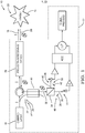
- Fig. 1 illustrates a non-limiting example of a coherent lidar system 10, hereafter referred to as the system 10, which is suitable for use on an automated vehicle 12.
- the term 'automated vehicle' is not meant to suggest that fully automated or autonomous operation of the automated vehicle 12 is required. It is contemplated that the teachings presented herein are applicable to instances where the automated vehicle 12 is entirely manually operated by a human-operator (not shown) except for automated target detection by the system 10 which may merely activate an audible and/or visible warning to warn the human-operator of the presence of an object or a target 14 proximate to the automated vehicle 12.
- the automated vehicle 12 may be operable in an automated-mode which may be a fully autonomous type of operation where the human-operator does little more than designate a destination, and/or the automated vehicle 12 may be operable in a manual-mode where the human-operator generally controls the steering, accelerator, and brakes of the automated vehicle 12. It is also contemplated that the teaching present herein are applicable to non-automotive applications where laser light is used to detect, for example, the presence, composition, and/or characteristics of various chemicals.
- the system 10 includes a laser-unit 16 used to provide a laser-beam 18 directed toward a target-area 20 and generate a local-oscillator 22, which is characterized by a reference-polarization 24, for example a vertical linear polarization as suggested in the illustration.
- a reference-polarization 24 for example a vertical linear polarization as suggested in the illustration.
- the same output from the laser-unit 16 used for the local-oscillator 22 is also used to generate the laser-beam 18 so the local-oscillator 22 and the laser-beam 18 have the same polarization.
- the system 10 could include a quarter-wave-polarizer (QWP) positioned so the laser-beam 18 is circularly polarized, and some other polarization may be applied to the local oscillator 22.
- QWP quarter-wave-polarizer
- the polarization of the laser-beam 18 is not critical as the system 10 is able to coherently detect the target 14 regardless of the polarization of the reflected-light 26 because the system 10 decomposes the reflected-light 26 into two orthogonal vectors or states. Because the two vectors are orthogonal and complete, total optical power of the reflected-light 26 will be conserved. However, as will be recognized by those in the art, it may be advantageous for the local-oscillator 22 and the laser-beam 18 to have certain polarizations, which are not necessarily the same, depending on the nature of the target 14.
- the laser-unit 16 is a semiconductor type laser that uses a laser diode (LD), which may also be known as an injection laser diode (ILD) to generate laser-light, as the power requirements, cost, and complexity are relatively low when compared to other technologies. That the system 10 described herein uses coherent detection enables the use of a laser diode to detect objects or targets at distances sufficient to be useful in automotive applications. It is also preferable that the laser-unit 16 be configured to output a frequency modulated continuous wave (FMCW) form of the local-oscillator 22 and the laser-beam 18 which can improve receiver sensitivity, reduce range dependence, and avoid the high peak power required of the output laser when compared to a lidar that operates based on laser pulses.
- FMCW frequency modulated continuous wave
- the low laser power requirement and potential to cover a long range with semiconductor lasers operating in the FMCW mode makes using coherent detection particularly attractive for vehicle applications.
- the system 10 also includes a lens 28 used to collect the reflected-light 26 that is a reflection of the laser-beam 18 reflected by the target 14 present in the target-area 20. While Fig. 1 suggests that the laser-beam and the reflected-light 26 pass through the same optical-devices that form the lens 28, this is not a requirement, and is only shown this way for convenience. Alternatively, the laser-beam 18 and the reflected-light 26 may be focused and/or directed by completely independent devices, as will be recognized by those in the art.
- the system 10 also includes a coupler 30 used to combine the reflected-light 26 collected by the lens 28 with the local-oscillator 22 to form a composite-beam 32.
- the coupler 30 is a fiber-coupler because for automotive applications fiber-optics are preferred to couple or propagate light about the system, e.g. to and from the lens 28.
- other means to couple or propagate the various light signals (e.g. the local-oscillator and the composite-beam 32) about the system 10 are envisioned such as mirrors and other optical devices used to control the propagation of light through 'free-space'.
- the fiber coupler that forms the coupler 30 is a commercially available device that provides a means to output the composite-beam 32 that is the result of interference between the local-oscillator 22 and the reflected-light 26 so that coherent detection of the reflected-light 26 is possible. It is necessary that the polarization of the local-oscillator 22 present in the composite-beam is known so that, as will be explained in more detail below, coherent detection can be performed without relying on an actively controlled polarizer to match or align the polarization of the reflected-light 26 to the reference-polarization 24 of the local-oscillator 22.
- the system 10 also includes a polarized-beam-splitter 34 used to provide a first-beam 36 that corresponds to the composite-beam 32 polarized to a first-polarization 38, and a second-beam 40 that corresponds to the composite-beam 32 polarized to a second-polarization 42 different from the first-polarization 38. That is, the first-beam 36 is made up of the portion of the composite-beam 32 that corresponds to the first-polarization 38, and the second-beam 40 is made up of the portion of the composite-beam 32 that corresponds to the first polarization 38.
- the first-polarization 38 and the second-polarization 42 are selected so a first-power 44 of the local-oscillator 22 present in the first-beam 36 is substantially equal (e.g. +/- 5%) to a second-power 46 of the local-oscillator 22 present in the second-beam 40. It should be appreciated that the more equal the first-power 44 is to the second-power 46, the better the system 10 operates. However, it is not a requirement that the first-power 44 be exactly equal to the second-power 46.
- Fig. 2 is a non-limiting example of the relationships of signals present in the system 10 shown in Fig. 1 .
- the reference-polarization 24 of the local-oscillator 22 is characterized as linear-polarization to a reference-angel 54, zero degrees (0°) for example.
- the value of the reference-angle 54 can be assigned any value, but one convention suggests zero degrees is preferred to simplify the explanation.
- the first-polarization 38 is characterized as linear-polarization to a first-angle 48 measured relative to the reference-angle 54, minus forty-five degrees (-45°) for example
- the second-polarization 42 is characterized as linear-polarization to a second-angle 50 measured relative to the reference-angle 54, plus forty-five degrees (+45°) for example.
- the second-angle 50 is perpendicular to the first-angle 48.
- the system 10 would operate if the second-angle 50 is not precisely perpendicular to the first-angle 48.
- Fig. 3 illustrates an alternative, non-limiting configuration of the system 10 where the reference-polarization 24 of the local-oscillator 22 is characterized as linear-polarization to a reference-angel 54, the first-polarization 38 is characterized as clockwise-polarization, and the second-polarization 42 is characterized as counter-clockwise-polarization.
- the configuration of the polarized-beam-splitter 34 in this example may include a quarter-wave-polarizer (QWP), which would be different from that used in Fig. 1 .
- QWP quarter-wave-polarizer
- the system 10 includes a first-detector 60 used to provide a first-signal 62 indicative of, for example, the optical power or intensity of the first-beam 36, and a second-detector 64 used to provide a second-signal 66 indicative, for example, the optical power or intensity of the second-beam 40.
- the system 10 also includes a processor 68 configured to combine the first-signal 62 and the second-signal 64 using a sum-of-squares process to provide a ranging-signal 70 indicative of a distance 72 to the target 14. After the sum-of-squares process of the two photodiode currents, the final result is proportional to the square of the optical power and independent to the original polarization, and this is the key idea of this disclosure. The details of process provide by the processor 68 are explained below.
- ⁇ is the frequency ramping rate in the frequency chirping
- R is the photodiode responsivity.
- a coherent lidar system (the system 10), a processor 68 for the system 10, and a method of operating the system 10 is provided.
- the system 10 includes:
Landscapes
- Engineering & Computer Science (AREA)
- Physics & Mathematics (AREA)
- Radar, Positioning & Navigation (AREA)
- Remote Sensing (AREA)
- Computer Networks & Wireless Communication (AREA)
- General Physics & Mathematics (AREA)
- Electromagnetism (AREA)
- Optical Radar Systems And Details Thereof (AREA)
Abstract
Description
- This disclosure generally relates to a coherent lidar system, and more particularly relates to a system that includes a polarized-beam-splitter used to provide a first-beam that corresponds to a composite-beam formed of a local-oscillator and reflected light polarized to a first-polarization, and a second-beam that corresponds to the composite-beam polarized to a second-polarization different from the first-polarization.
- It is known that by utilizing coherent optical detection, a frequency modulated continuous wave (FMCW) lidar can improve receiver sensitivity, reduce range dependence, and avoid the high peak power required of the output laser when compared to a lidar that operates based on laser pulses. The low laser power requirement and potential to cover a long range with semiconductor lasers makes coherent detection particularly attractive for vehicle applications. However, the coherent detection is based on the interference between the reflected-light reflected by a target and a polarized local-oscillator (LO) signal, and only the reflected-light components with the same polarization can provide the interference necessary for coherent detection. Unfortunately, coherent detection is sensitive to the polarization of the return beam, which is subject to many factors out of control of the lidar. Normally, in order to optimize the signal-to-noise ratio (SNR), the polarization of the return signal and the local-oscillator signal must be carefully aligned, which historically requires an electro-mechanical or electro-optical feedback loop or polarization controller to align the polarization of the return signal with the local-oscillator signal. Available examples of a polarization controller are typically too bulky and expensive for use on space and cost sensitive automotive applications.
- The problem of the system sensitivity to the polarization state of the return optical signal is solved by combining the local-oscillator signal and the returned signal in a fiber coupler and then separating the combined signal using a polarization beam splitter. The orientation of the splitter is selected such that the two output beams from the splitter have the same power when there is local-oscillator signal input only. After photo detection and amplification, the current signal of the two channels will be combined as a sum of square for the further signal process. It is noted that after the combination, the signal power or amplitude will be independent from the polarization state of the optical return signal from target.
- In accordance with one embodiment, a coherent lidar system suitable for use on an automated vehicle is provided. The system includes a laser-unit, a lens, a coupler, and a polarized-beam-splitter. The laser-unit is used to provide a laser-beam directed toward a target-area and generate a local-oscillator. The local-oscillator is characterized by a reference-polarization. The lens is used to collect reflected-light that is a reflection of the laser-beam by a target present in the target-area. The coupler is used to combine the reflected-light collected by the lens and the local-oscillator to form a composite-beam. The polarized-beam-splitter used to provide a first-beam that corresponds to the composite-beam polarized to a first-polarization, and a second-beam that corresponds to the composite-beam polarized to a second-polarization different from the first-polarization.
- The first-polarization and the second-polarization may be selected so a first-power of the local-oscillator present in the first-beam is substantially equal to a second-power of the local-oscillator present in the second-beam.
- The reference-polarization of the local-oscillator may be characterized as linear-polarization to a reference-angel, the first-polarization may be characterized as linear-polarization to a first-angle measured relative to the reference-angle, and the second-polarization may be characterized as linear-polarization to a second-angle measured relative to the reference-angle. The second-angle may be perpendicular to the first-angle. The first-angle may be minus forty-five degrees relative to the reference-angle, and the second-angle may be plus forty-five degrees relative to the reference-angle. The reference-polarization of the local-oscillator may be characterized as linear-polarization to a reference-angel, the first-polarization may be characterized as clockwise-polarization, and the second-polarization may be characterized as counter-clockwise-polarization. The laser-unit may be configured to frequency-modulate the laser-beam and the local-oscillator.
- The system may include a first-detector used to provide a first-signal indicative of the first-beam, and a second-detector used to provide a second-signal indicative of the second-beam. The system may include a processor configured to combine the first-signal and the second-signal using a sum-of-squares process to provide a ranging-signal indicate of a distance to the target.
- Further features and advantages will appear more clearly on a reading of the following detailed description of the preferred embodiment, which is given by way of non-limiting example only and with reference to the accompanying drawings.
- The present invention will now be described, by way of example with reference to the accompanying drawings, in which:
-
Fig. 1 is a diagram of a coherent lidar system in accordance with one embodiment; -
Fig. 2 is a representation of polarizations of light signals present in the system ofFig. 1 in accordance with one embodiment; and -
Fig. 3 is an alternative diagram of a coherent lidar system that is an alternative to the system ofFig. 1 in accordance with one embodiment. -
Fig. 1 illustrates a non-limiting example of acoherent lidar system 10, hereafter referred to as thesystem 10, which is suitable for use on anautomated vehicle 12. As used herein, the term 'automated vehicle' is not meant to suggest that fully automated or autonomous operation of theautomated vehicle 12 is required. It is contemplated that the teachings presented herein are applicable to instances where theautomated vehicle 12 is entirely manually operated by a human-operator (not shown) except for automated target detection by thesystem 10 which may merely activate an audible and/or visible warning to warn the human-operator of the presence of an object or atarget 14 proximate to theautomated vehicle 12. That is, theautomated vehicle 12 may be operable in an automated-mode which may be a fully autonomous type of operation where the human-operator does little more than designate a destination, and/or theautomated vehicle 12 may be operable in a manual-mode where the human-operator generally controls the steering, accelerator, and brakes of theautomated vehicle 12. It is also contemplated that the teaching present herein are applicable to non-automotive applications where laser light is used to detect, for example, the presence, composition, and/or characteristics of various chemicals. - The
system 10 includes a laser-unit 16 used to provide a laser-beam 18 directed toward a target-area 20 and generate a local-oscillator 22, which is characterized by a reference-polarization 24, for example a vertical linear polarization as suggested in the illustration. In this non-limiting example the same output from the laser-unit 16 used for the local-oscillator 22 is also used to generate the laser-beam 18 so the local-oscillator 22 and the laser-beam 18 have the same polarization. However, this is not a requirement. For example, thesystem 10 could include a quarter-wave-polarizer (QWP) positioned so the laser-beam 18 is circularly polarized, and some other polarization may be applied to thelocal oscillator 22. As will become clear in the explanation that follows, the polarization of the laser-beam 18 is not critical as thesystem 10 is able to coherently detect thetarget 14 regardless of the polarization of the reflected-light 26 because thesystem 10 decomposes the reflected-light 26 into two orthogonal vectors or states. Because the two vectors are orthogonal and complete, total optical power of the reflected-light 26 will be conserved. However, as will be recognized by those in the art, it may be advantageous for the local-oscillator 22 and the laser-beam 18 to have certain polarizations, which are not necessarily the same, depending on the nature of thetarget 14. - Preferably, the laser-
unit 16 is a semiconductor type laser that uses a laser diode (LD), which may also be known as an injection laser diode (ILD) to generate laser-light, as the power requirements, cost, and complexity are relatively low when compared to other technologies. That thesystem 10 described herein uses coherent detection enables the use of a laser diode to detect objects or targets at distances sufficient to be useful in automotive applications. It is also preferable that the laser-unit 16 be configured to output a frequency modulated continuous wave (FMCW) form of the local-oscillator 22 and the laser-beam 18 which can improve receiver sensitivity, reduce range dependence, and avoid the high peak power required of the output laser when compared to a lidar that operates based on laser pulses. The low laser power requirement and potential to cover a long range with semiconductor lasers operating in the FMCW mode makes using coherent detection particularly attractive for vehicle applications. - The
system 10 also includes alens 28 used to collect the reflected-light 26 that is a reflection of the laser-beam 18 reflected by thetarget 14 present in the target-area 20. WhileFig. 1 suggests that the laser-beam and the reflected-light 26 pass through the same optical-devices that form thelens 28, this is not a requirement, and is only shown this way for convenience. Alternatively, the laser-beam 18 and the reflected-light 26 may be focused and/or directed by completely independent devices, as will be recognized by those in the art. - The
system 10 also includes acoupler 30 used to combine the reflected-light 26 collected by thelens 28 with the local-oscillator 22 to form a composite-beam 32. In this non-limiting example, thecoupler 30 is a fiber-coupler because for automotive applications fiber-optics are preferred to couple or propagate light about the system, e.g. to and from thelens 28. However, other means to couple or propagate the various light signals (e.g. the local-oscillator and the composite-beam 32) about thesystem 10 are envisioned such as mirrors and other optical devices used to control the propagation of light through 'free-space'. The fiber coupler that forms thecoupler 30 is a commercially available device that provides a means to output the composite-beam 32 that is the result of interference between the local-oscillator 22 and the reflected-light 26 so that coherent detection of the reflected-light 26 is possible. It is necessary that the polarization of the local-oscillator 22 present in the composite-beam is known so that, as will be explained in more detail below, coherent detection can be performed without relying on an actively controlled polarizer to match or align the polarization of the reflected-light 26 to the reference-polarization 24 of the local-oscillator 22. - The
system 10 also includes a polarized-beam-splitter 34 used to provide a first-beam 36 that corresponds to the composite-beam 32 polarized to a first-polarization 38, and a second-beam 40 that corresponds to the composite-beam 32 polarized to a second-polarization 42 different from the first-polarization 38. That is, the first-beam 36 is made up of the portion of the composite-beam 32 that corresponds to the first-polarization 38, and the second-beam 40 is made up of the portion of the composite-beam 32 that corresponds to thefirst polarization 38. Advantageously, the first-polarization 38 and the second-polarization 42 are selected so a first-power 44 of the local-oscillator 22 present in the first-beam 36 is substantially equal (e.g. +/- 5%) to a second-power 46 of the local-oscillator 22 present in the second-beam 40. It should be appreciated that the more equal the first-power 44 is to the second-power 46, the better thesystem 10 operates. However, it is not a requirement that the first-power 44 be exactly equal to the second-power 46. -
Fig. 2 is a non-limiting example of the relationships of signals present in thesystem 10 shown inFig. 1 . As mentioned before for this non-limiting example, the reference-polarization 24 of the local-oscillator 22 is characterized as linear-polarization to a reference-angel 54, zero degrees (0°) for example. The value of the reference-angle 54 can be assigned any value, but one convention suggests zero degrees is preferred to simplify the explanation. The first-polarization 38 is characterized as linear-polarization to a first-angle 48 measured relative to the reference-angle 54, minus forty-five degrees (-45°) for example, and the second-polarization 42 is characterized as linear-polarization to a second-angle 50 measured relative to the reference-angle 54, plus forty-five degrees (+45°) for example. Advantageously, the second-angle 50 is perpendicular to the first-angle 48. However, it is recognized that thesystem 10 would operate if the second-angle 50 is not precisely perpendicular to the first-angle 48. -
Fig. 3 illustrates an alternative, non-limiting configuration of thesystem 10 where the reference-polarization 24 of the local-oscillator 22 is characterized as linear-polarization to a reference-angel 54, the first-polarization 38 is characterized as clockwise-polarization, and the second-polarization 42 is characterized as counter-clockwise-polarization. As will be recognized by those in the art, the configuration of the polarized-beam-splitter 34 in this example may include a quarter-wave-polarizer (QWP), which would be different from that used inFig. 1 . - Continuing to refer to
Figs. 1 and3 , thesystem 10 includes a first-detector 60 used to provide a first-signal 62 indicative of, for example, the optical power or intensity of the first-beam 36, and a second-detector 64 used to provide a second-signal 66 indicative, for example, the optical power or intensity of the second-beam 40. - The
system 10 also includes aprocessor 68 configured to combine the first-signal 62 and the second-signal 64 using a sum-of-squares process to provide a ranging-signal 70 indicative of adistance 72 to thetarget 14. After the sum-of-squares process of the two photodiode currents, the final result is proportional to the square of the optical power and independent to the original polarization, and this is the key idea of this disclosure. The details of process provide by theprocessor 68 are explained below. - Assuming the powers of the local-oscillator signal and the return signal are PLO and Ps and the time delay caused by the target is Ttarget, their E components on the polarization in the orientation of
channel 1 and 2 are:
Channel 1:

Channel 2:

- After photodetection, the optical frequency and DC components will be rejected by the receiver, and only the beat signal will be left for further process. Then, the AC current in each channel is


- Then, the sum of square of the two will be

- As expected, it is independent to the return signal polarization and no signal power is lost in the process. By analyzing its frequency, we can extract the ranging information of the target.
- Accordingly, a coherent lidar system (the system 10), a
processor 68 for thesystem 10, and a method of operating thesystem 10 is provided. Features of thesystem 10 include: - Different polarization control strategy: Prior examples of coherent detection system try to align the polarization of the reflected-light 26 with local-
oscillator 22 and it is a dynamic or active process. In thesystem 10 described herein, there is no control of the polarization of the reflected-light 26. Instead, the polarized-beam-splitter 34 and two receiver channels were used. The polarization dependence was eliminated after a current sum of square of the two channels. - This solution can be applied to both fiber optics and free space optics.
- This solution can be applied to linear, circular, and other orthogonal polarizations.
- The receiver optics can be separated from the projecting optics and avoid the circulator depicted in
Figs 1 and3 . - The receivers are recommended to be balanced receivers, but normal receiver with sufficient dynamic range and AC output will also work.
- The ADC for the receiver channels can be done before or after the sum of square process.
- The alignment of the polarization splitter to the local-oscillator polarization splits the local-oscillator power evenly between the two receiver channels to ensure a complete elimination of the polarization dependence of the output.
- While this invention has been described in terms of the preferred embodiments thereof, it is not intended to be so limited, but rather only to the extent set forth in the claims that follow.
Claims (9)
- A coherent lidar system (10) suitable for use on an automated vehicle (12), said system (10) comprising:a laser-unit (16) used to provide a laser-beam (18) directed toward a target-area (20) and generate a local-oscillator (22), wherein the local-oscillator (22) is characterized by a reference-polarization (24);a lens (28) used to collect reflected-light (26) that is a reflection of the laser-beam (18) by a target (14) present in the target-area (20);a coupler (30) used to combine the reflected-light (26) collected by the lens (28) and the local-oscillator (22) to form a composite-beam (32); anda polarized-beam-splitter (34) used to provide a first-beam (36) that corresponds to the composite-beam (32) polarized to a first-polarization (38), and a second-beam (40) that corresponds to the composite-beam (32) polarized to a second-polarization (42) different from the first-polarization (38).
- The system (10) in accordance with claim 1, wherein the first-polarization (38) and the second-polarization (42) are selected so a first-power (44) of the local-oscillator (22) present in the first-beam (36) is substantially equal to a second-power (46) of the local-oscillator (22) present in the second-beam (40).
- The system (10) according to any one of the preceding claims, wherein the reference-polarization (24) of the local-oscillator (22) is characterized as linear-polarization to a reference-angel (54), the first-polarization (38) is characterized as linear-polarization to a first-angle (48) measured relative to the reference-angle (54), and the second-polarization (42) is characterized as linear-polarization to a second-angle (50) measured relative to the reference-angle (54).
- The system (10) in accordance with claim 3, wherein the second-angle (50) is perpendicular to the first-angle (48).
- The system (10) in accordance with claim 4, wherein the first-angle (48) is minus forty-five degrees relative to the reference-angle (54), and the second-angle (50) is plus forty-five degrees relative to the reference-angle (54).
- The system (10) according to any one of the preceding claims, wherein the reference-polarization (24) of the local-oscillator (22) is characterized as linear-polarization to a reference-angel (54), the first-polarization (38) is characterized as clockwise-polarization, and the second-polarization (42) is characterized as counter-clockwise-polarization.
- The system (10) according to any one of the preceding claims, wherein the laser-unit (16) is configured to frequency-modulate the laser-beam (18) and the local-oscillator (22).
- The system (10) according to any one of the preceding claims, wherein the system (10) includes a first-detector (60) used to provide a first-signal (62) indicative of the first-beam (36), and a second-detector (64) used to provide a second-signal (64) indicative of the second-beam (40).
- The system (10) according to any one of the claims 4 or 5, wherein the system (10) includes a processor (68) configured to combine the first-signal (62) and the second-signal (64) using a sum-of-squares process to provide a ranging-signal (70) indicate of a distance (72) to the target (14).
Applications Claiming Priority (1)
| Application Number | Priority Date | Filing Date | Title |
|---|---|---|---|
| US15/268,733 US20180081031A1 (en) | 2016-09-19 | 2016-09-19 | Coherent lidar system for automated vehicles |
Publications (1)
| Publication Number | Publication Date |
|---|---|
| EP3296764A1 true EP3296764A1 (en) | 2018-03-21 |
Family
ID=59887081
Family Applications (1)
| Application Number | Title | Priority Date | Filing Date |
|---|---|---|---|
| EP17191189.4A Withdrawn EP3296764A1 (en) | 2016-09-19 | 2017-09-14 | Coherent lidar system for automated vehicles |
Country Status (3)
| Country | Link |
|---|---|
| US (1) | US20180081031A1 (en) |
| EP (1) | EP3296764A1 (en) |
| CN (1) | CN107843888A (en) |
Cited By (3)
| Publication number | Priority date | Publication date | Assignee | Title |
|---|---|---|---|---|
| KR20210141709A (en) * | 2019-03-29 | 2021-11-23 | 아워스 테크놀로지, 엘엘씨. | Switchable Coherent Pixel Array for Frequency Modulated Continuous Wave Light Sensing and Distance Measurement |
| CN113841065A (en) * | 2019-03-18 | 2021-12-24 | 艾娃有限公司 | LIDAR device with optical amplifier in return path |
| US12444068B2 (en) | 2022-08-01 | 2025-10-14 | Lg Innotek Co., Ltd. | Optical inspection based on repetitive feature comparison |
Families Citing this family (16)
| Publication number | Priority date | Publication date | Assignee | Title |
|---|---|---|---|---|
| US11226403B2 (en) * | 2017-07-12 | 2022-01-18 | GM Global Technology Operations LLC | Chip-scale coherent lidar with integrated high power laser diode |
| US11073618B2 (en) * | 2018-04-03 | 2021-07-27 | GM Global Technology Operations LLC | Optical amplifier in return path of coherent lidar system |
| US11119218B2 (en) * | 2018-04-03 | 2021-09-14 | GM Global Technology Operations LLC | Coherent lidar system with extended field of view |
| US20190302262A1 (en) * | 2018-04-03 | 2019-10-03 | GM Global Technology Operations LLC | Light conveyance in a lidar system with a monocentric lens |
| CN108279423A (en) * | 2018-05-03 | 2018-07-13 | 江苏亮点光电科技有限公司 | A kind of laser range finder with the interference of anti-sunlight |
| CN108844870B (en) * | 2018-08-08 | 2021-09-21 | 重庆交通大学 | PM based on optical fiber structure10And PM2.5Probe instrument apparatus and system |
| US11733361B2 (en) * | 2018-09-06 | 2023-08-22 | Aeva, Inc. | Polarization encoded beam delivery and collection |
| US11402472B2 (en) | 2019-04-16 | 2022-08-02 | Argo AI, LLC | Polarization sensitive LiDAR system |
| WO2020217267A1 (en) * | 2019-04-22 | 2020-10-29 | 三菱電機株式会社 | Laser radar device |
| WO2021150447A1 (en) * | 2020-01-24 | 2021-07-29 | Argo AI, LLC | Systems and methods for light backscattering mitigation in lidar systems |
| US11774564B2 (en) | 2020-02-06 | 2023-10-03 | Aptiv Technologies Limited | Low-cost readout module for a lidar system |
| US10948600B1 (en) * | 2020-06-29 | 2021-03-16 | Aurora Innovation, Inc. | Systems and methods for IQ detection |
| US10960900B1 (en) * | 2020-06-30 | 2021-03-30 | Aurora Innovation, Inc. | Systems and methods for autonomous vehicle control using depolarization ratio of return signal |
| US11435454B2 (en) * | 2020-09-04 | 2022-09-06 | Ours Technology, Llc | Beam walkoff mitigation for light detection and ranging |
| US12429587B2 (en) * | 2022-04-05 | 2025-09-30 | Aeva, Inc. | Techniques for equalizing powers of multiple local oscillator beams using optical attenuators |
| WO2023225284A1 (en) * | 2022-05-20 | 2023-11-23 | Ours Technology, Llc | Lidar with switchable local oscillator signals |
Citations (3)
| Publication number | Priority date | Publication date | Assignee | Title |
|---|---|---|---|---|
| US5114226A (en) * | 1987-03-20 | 1992-05-19 | Digital Optronics Corporation | 3-Dimensional vision system utilizing coherent optical detection |
| US20100268499A1 (en) * | 2007-11-21 | 2010-10-21 | Wolfgang Holzapfel | Interferometer system and method for its operation |
| EP3182152A1 (en) * | 2014-08-12 | 2017-06-21 | Mitsubishi Electric Corporation | Laser light sending and receiving device and laser radar device |
Family Cites Families (5)
| Publication number | Priority date | Publication date | Assignee | Title |
|---|---|---|---|---|
| US4621926A (en) * | 1985-04-30 | 1986-11-11 | Lasercon Corporation | Interferometer system for controlling non-rectilinear movement of an object |
| US5574553A (en) * | 1994-12-27 | 1996-11-12 | The United States Of America As Represented By The Secretary Of The Air Force | Ladar receiver incorporating an optical amplifier and polarization optical mixer |
| US20020109829A1 (en) * | 1999-10-28 | 2002-08-15 | Hayes Cecil L. | Single aperture, alignment insensitive ladar system |
| EP1713377A1 (en) * | 2004-02-10 | 2006-10-25 | Optovue, Inc. | High efficiency low coherence interferometry |
| CN107567592B (en) * | 2015-04-07 | 2021-07-16 | 闪光股份有限公司 | Small lidar system |
-
2016
- 2016-09-19 US US15/268,733 patent/US20180081031A1/en not_active Abandoned
-
2017
- 2017-09-14 EP EP17191189.4A patent/EP3296764A1/en not_active Withdrawn
- 2017-09-18 CN CN201710840563.5A patent/CN107843888A/en not_active Withdrawn
Patent Citations (3)
| Publication number | Priority date | Publication date | Assignee | Title |
|---|---|---|---|---|
| US5114226A (en) * | 1987-03-20 | 1992-05-19 | Digital Optronics Corporation | 3-Dimensional vision system utilizing coherent optical detection |
| US20100268499A1 (en) * | 2007-11-21 | 2010-10-21 | Wolfgang Holzapfel | Interferometer system and method for its operation |
| EP3182152A1 (en) * | 2014-08-12 | 2017-06-21 | Mitsubishi Electric Corporation | Laser light sending and receiving device and laser radar device |
Cited By (5)
| Publication number | Priority date | Publication date | Assignee | Title |
|---|---|---|---|---|
| CN113841065A (en) * | 2019-03-18 | 2021-12-24 | 艾娃有限公司 | LIDAR device with optical amplifier in return path |
| CN113841065B (en) * | 2019-03-18 | 2024-05-03 | 艾娃有限公司 | LIDAR device with optical amplifier in return path |
| KR20210141709A (en) * | 2019-03-29 | 2021-11-23 | 아워스 테크놀로지, 엘엘씨. | Switchable Coherent Pixel Array for Frequency Modulated Continuous Wave Light Sensing and Distance Measurement |
| US12326522B2 (en) | 2019-03-29 | 2025-06-10 | Aurora Opeations, Inc. | Switchable coherent pixel array for frequency modulated continuous wave light detection and ranging |
| US12444068B2 (en) | 2022-08-01 | 2025-10-14 | Lg Innotek Co., Ltd. | Optical inspection based on repetitive feature comparison |
Also Published As
| Publication number | Publication date |
|---|---|
| US20180081031A1 (en) | 2018-03-22 |
| CN107843888A (en) | 2018-03-27 |
Similar Documents
| Publication | Publication Date | Title |
|---|---|---|
| US20180081031A1 (en) | Coherent lidar system for automated vehicles | |
| CN109254278B (en) | Calibration and alignment of coherent lidar systems | |
| EP3942329B1 (en) | Lidar apparatus with an optical amplifier in the return path | |
| US20230129755A1 (en) | Spatial profiling system and method | |
| US11982774B2 (en) | Techniques for combining optical beams into shared spatial mode | |
| CN110346777B (en) | Optical amplifier in return path of coherent lidar system | |
| US11079480B2 (en) | FMCW lidar with wavelength diversity | |
| US9971025B2 (en) | Method for determining the distance of an object by means of a polarization-modulated transmission light beam | |
| KR102536707B1 (en) | Combining multiple functions of a LIDAR system to support vehicle motion | |
| US9007569B2 (en) | Coherent doppler lidar for measuring altitude, ground velocity, and air velocity of aircraft and spaceborne vehicles | |
| US11353558B2 (en) | Multiple laser, single resonator lidar | |
| US20140241731A1 (en) | System and method for free space optical communication beam acquisition | |
| US20240094357A1 (en) | Coherent pulsed lidar system | |
| US6876441B2 (en) | Optical sensor for distance measurement | |
| US12481031B2 (en) | Hybrid pulsed/coherent lidar system with spectral signatures | |
| US20240201337A1 (en) | Coherent pulsed lidar system | |
| Sharma et al. | Impact of bandwidth on range resolution of multiple targets using photonic radar | |
| Zhang et al. | Comprehensive ranging disambiguation for amplitude-modulated continuous-wave laser scanner with focusing optics | |
| US10101600B2 (en) | Systems and methods for amplification of back-scattered signal by laser source cavity | |
| US12146956B2 (en) | Polarization diversity detection in FMCW Lidar | |
| WO2024112858A2 (en) | Coherent pulsed lidar system | |
| RU2116672C1 (en) | Method for detection of intrusion into monitored space with guarded object and device which implements said method |
Legal Events
| Date | Code | Title | Description |
|---|---|---|---|
| PUAI | Public reference made under article 153(3) epc to a published international application that has entered the european phase |
Free format text: ORIGINAL CODE: 0009012 |
|
| AK | Designated contracting states |
Kind code of ref document: A1 Designated state(s): AL AT BE BG CH CY CZ DE DK EE ES FI FR GB GR HR HU IE IS IT LI LT LU LV MC MK MT NL NO PL PT RO RS SE SI SK SM TR |
|
| AX | Request for extension of the european patent |
Extension state: BA ME |
|
| 17P | Request for examination filed |
Effective date: 20180921 |
|
| RBV | Designated contracting states (corrected) |
Designated state(s): AL AT BE BG CH CY CZ DE DK EE ES FI FR GB GR HR HU IE IS IT LI LT LU LV MC MK MT NL NO PL PT RO RS SE SI SK SM TR |
|
| RAP1 | Party data changed (applicant data changed or rights of an application transferred) |
Owner name: APTIV TECHNOLOGIES LIMITED |
|
| GRAP | Despatch of communication of intention to grant a patent |
Free format text: ORIGINAL CODE: EPIDOSNIGR1 |
|
| STAA | Information on the status of an ep patent application or granted ep patent |
Free format text: STATUS: GRANT OF PATENT IS INTENDED |
|
| RIC1 | Information provided on ipc code assigned before grant |
Ipc: G01S 17/34 20200101ALI20200401BHEP Ipc: G01S 7/499 20060101ALI20200401BHEP Ipc: G01S 7/4912 20200101AFI20200401BHEP |
|
| INTG | Intention to grant announced |
Effective date: 20200424 |
|
| STAA | Information on the status of an ep patent application or granted ep patent |
Free format text: STATUS: THE APPLICATION IS DEEMED TO BE WITHDRAWN |
|
| 18D | Application deemed to be withdrawn |
Effective date: 20200905 |