EP3182152A1 - Laser light sending and receiving device and laser radar device - Google Patents
Laser light sending and receiving device and laser radar device Download PDFInfo
- Publication number
- EP3182152A1 EP3182152A1 EP14899693.7A EP14899693A EP3182152A1 EP 3182152 A1 EP3182152 A1 EP 3182152A1 EP 14899693 A EP14899693 A EP 14899693A EP 3182152 A1 EP3182152 A1 EP 3182152A1
- Authority
- EP
- European Patent Office
- Prior art keywords
- light beam
- polarization
- laser light
- reflected light
- optical system
- Prior art date
- Legal status (The legal status is an assumption and is not a legal conclusion. Google has not performed a legal analysis and makes no representation as to the accuracy of the status listed.)
- Granted
Links
- 230000010287 polarization Effects 0.000 claims abstract description 330
- 230000005540 biological transmission Effects 0.000 claims abstract description 101
- 230000003287 optical effect Effects 0.000 claims description 182
- 230000003247 decreasing effect Effects 0.000 abstract description 5
- 239000002131 composite material Substances 0.000 description 25
- 238000010586 diagram Methods 0.000 description 12
- 239000013307 optical fiber Substances 0.000 description 6
- 238000001514 detection method Methods 0.000 description 5
- 230000005684 electric field Effects 0.000 description 4
- 239000000443 aerosol Substances 0.000 description 3
- 230000000694 effects Effects 0.000 description 3
- 230000001360 synchronised effect Effects 0.000 description 3
- 238000005259 measurement Methods 0.000 description 2
- 239000010409 thin film Substances 0.000 description 2
- 239000013585 weight reducing agent Substances 0.000 description 2
- 230000005374 Kerr effect Effects 0.000 description 1
- 229910003327 LiNbO3 Inorganic materials 0.000 description 1
- 230000005697 Pockels effect Effects 0.000 description 1
- 230000007423 decrease Effects 0.000 description 1
- GQYHUHYESMUTHG-UHFFFAOYSA-N lithium niobate Chemical compound [Li+].[O-][Nb](=O)=O GQYHUHYESMUTHG-UHFFFAOYSA-N 0.000 description 1
- 239000000203 mixture Substances 0.000 description 1
- 230000005693 optoelectronics Effects 0.000 description 1
- 230000003252 repetitive effect Effects 0.000 description 1
- 230000035939 shock Effects 0.000 description 1
- 230000001052 transient effect Effects 0.000 description 1
Images


Classifications
-
- G—PHYSICS
- G01—MEASURING; TESTING
- G01S—RADIO DIRECTION-FINDING; RADIO NAVIGATION; DETERMINING DISTANCE OR VELOCITY BY USE OF RADIO WAVES; LOCATING OR PRESENCE-DETECTING BY USE OF THE REFLECTION OR RERADIATION OF RADIO WAVES; ANALOGOUS ARRANGEMENTS USING OTHER WAVES
- G01S7/00—Details of systems according to groups G01S13/00, G01S15/00, G01S17/00
- G01S7/48—Details of systems according to groups G01S13/00, G01S15/00, G01S17/00 of systems according to group G01S17/00
- G01S7/481—Constructional features, e.g. arrangements of optical elements
- G01S7/4811—Constructional features, e.g. arrangements of optical elements common to transmitter and receiver
-
- G—PHYSICS
- G01—MEASURING; TESTING
- G01S—RADIO DIRECTION-FINDING; RADIO NAVIGATION; DETERMINING DISTANCE OR VELOCITY BY USE OF RADIO WAVES; LOCATING OR PRESENCE-DETECTING BY USE OF THE REFLECTION OR RERADIATION OF RADIO WAVES; ANALOGOUS ARRANGEMENTS USING OTHER WAVES
- G01S17/00—Systems using the reflection or reradiation of electromagnetic waves other than radio waves, e.g. lidar systems
- G01S17/02—Systems using the reflection of electromagnetic waves other than radio waves
- G01S17/50—Systems of measurement based on relative movement of target
- G01S17/58—Velocity or trajectory determination systems; Sense-of-movement determination systems
-
- G—PHYSICS
- G01—MEASURING; TESTING
- G01S—RADIO DIRECTION-FINDING; RADIO NAVIGATION; DETERMINING DISTANCE OR VELOCITY BY USE OF RADIO WAVES; LOCATING OR PRESENCE-DETECTING BY USE OF THE REFLECTION OR RERADIATION OF RADIO WAVES; ANALOGOUS ARRANGEMENTS USING OTHER WAVES
- G01S17/00—Systems using the reflection or reradiation of electromagnetic waves other than radio waves, e.g. lidar systems
- G01S17/88—Lidar systems specially adapted for specific applications
- G01S17/95—Lidar systems specially adapted for specific applications for meteorological use
-
- G—PHYSICS
- G01—MEASURING; TESTING
- G01S—RADIO DIRECTION-FINDING; RADIO NAVIGATION; DETERMINING DISTANCE OR VELOCITY BY USE OF RADIO WAVES; LOCATING OR PRESENCE-DETECTING BY USE OF THE REFLECTION OR RERADIATION OF RADIO WAVES; ANALOGOUS ARRANGEMENTS USING OTHER WAVES
- G01S7/00—Details of systems according to groups G01S13/00, G01S15/00, G01S17/00
- G01S7/48—Details of systems according to groups G01S13/00, G01S15/00, G01S17/00 of systems according to group G01S17/00
- G01S7/481—Constructional features, e.g. arrangements of optical elements
- G01S7/4811—Constructional features, e.g. arrangements of optical elements common to transmitter and receiver
- G01S7/4812—Constructional features, e.g. arrangements of optical elements common to transmitter and receiver transmitted and received beams following a coaxial path
-
- G—PHYSICS
- G01—MEASURING; TESTING
- G01S—RADIO DIRECTION-FINDING; RADIO NAVIGATION; DETERMINING DISTANCE OR VELOCITY BY USE OF RADIO WAVES; LOCATING OR PRESENCE-DETECTING BY USE OF THE REFLECTION OR RERADIATION OF RADIO WAVES; ANALOGOUS ARRANGEMENTS USING OTHER WAVES
- G01S7/00—Details of systems according to groups G01S13/00, G01S15/00, G01S17/00
- G01S7/48—Details of systems according to groups G01S13/00, G01S15/00, G01S17/00 of systems according to group G01S17/00
- G01S7/481—Constructional features, e.g. arrangements of optical elements
- G01S7/4817—Constructional features, e.g. arrangements of optical elements relating to scanning
-
- G—PHYSICS
- G01—MEASURING; TESTING
- G01S—RADIO DIRECTION-FINDING; RADIO NAVIGATION; DETERMINING DISTANCE OR VELOCITY BY USE OF RADIO WAVES; LOCATING OR PRESENCE-DETECTING BY USE OF THE REFLECTION OR RERADIATION OF RADIO WAVES; ANALOGOUS ARRANGEMENTS USING OTHER WAVES
- G01S7/00—Details of systems according to groups G01S13/00, G01S15/00, G01S17/00
- G01S7/48—Details of systems according to groups G01S13/00, G01S15/00, G01S17/00 of systems according to group G01S17/00
- G01S7/481—Constructional features, e.g. arrangements of optical elements
- G01S7/4818—Constructional features, e.g. arrangements of optical elements using optical fibres
-
- G—PHYSICS
- G01—MEASURING; TESTING
- G01S—RADIO DIRECTION-FINDING; RADIO NAVIGATION; DETERMINING DISTANCE OR VELOCITY BY USE OF RADIO WAVES; LOCATING OR PRESENCE-DETECTING BY USE OF THE REFLECTION OR RERADIATION OF RADIO WAVES; ANALOGOUS ARRANGEMENTS USING OTHER WAVES
- G01S7/00—Details of systems according to groups G01S13/00, G01S15/00, G01S17/00
- G01S7/48—Details of systems according to groups G01S13/00, G01S15/00, G01S17/00 of systems according to group G01S17/00
- G01S7/491—Details of non-pulse systems
- G01S7/4912—Receivers
- G01S7/4917—Receivers superposing optical signals in a photodetector, e.g. optical heterodyne detection
-
- G—PHYSICS
- G01—MEASURING; TESTING
- G01S—RADIO DIRECTION-FINDING; RADIO NAVIGATION; DETERMINING DISTANCE OR VELOCITY BY USE OF RADIO WAVES; LOCATING OR PRESENCE-DETECTING BY USE OF THE REFLECTION OR RERADIATION OF RADIO WAVES; ANALOGOUS ARRANGEMENTS USING OTHER WAVES
- G01S7/00—Details of systems according to groups G01S13/00, G01S15/00, G01S17/00
- G01S7/48—Details of systems according to groups G01S13/00, G01S15/00, G01S17/00 of systems according to group G01S17/00
- G01S7/499—Details of systems according to groups G01S13/00, G01S15/00, G01S17/00 of systems according to group G01S17/00 using polarisation effects
-
- G—PHYSICS
- G01—MEASURING; TESTING
- G01C—MEASURING DISTANCES, LEVELS OR BEARINGS; SURVEYING; NAVIGATION; GYROSCOPIC INSTRUMENTS; PHOTOGRAMMETRY OR VIDEOGRAMMETRY
- G01C3/00—Measuring distances in line of sight; Optical rangefinders
- G01C3/02—Details
- G01C3/06—Use of electric means to obtain final indication
-
- Y—GENERAL TAGGING OF NEW TECHNOLOGICAL DEVELOPMENTS; GENERAL TAGGING OF CROSS-SECTIONAL TECHNOLOGIES SPANNING OVER SEVERAL SECTIONS OF THE IPC; TECHNICAL SUBJECTS COVERED BY FORMER USPC CROSS-REFERENCE ART COLLECTIONS [XRACs] AND DIGESTS
- Y02—TECHNOLOGIES OR APPLICATIONS FOR MITIGATION OR ADAPTATION AGAINST CLIMATE CHANGE
- Y02A—TECHNOLOGIES FOR ADAPTATION TO CLIMATE CHANGE
- Y02A90/00—Technologies having an indirect contribution to adaptation to climate change
- Y02A90/10—Information and communication technologies [ICT] supporting adaptation to climate change, e.g. for weather forecasting or climate simulation
Definitions
- the present invention relates to a laser light transceiver that emits a laser light beam into space and receives a reflected light beam of the laser light beam, the reflected light beam being reflected by an observation target existing in the space, and a laser radar device that emits a laser light beam into space and receives a reflected light beam of the laser light beam, the reflected light beam being reflected by an observation target existing in the space, and that combines the reflected light beam and a local light beam, to acquire a beat signal.
- the laser light beam passing through the above-mentioned 1/4 wavelength plate is irradiated to a target existing in the space, and a reflected light beam of the laser light beam, the reflected light beam being reflected by the target and returning to the 1/4 wavelength plate, passes through the 1/4 wavelength plate again.
- the transmission light source 1 may alternatively output a circularly-polarized laser light beam.
- the reflecting mirror 3 is an optical component to reflect the p-polarized laser light beam outputted from the polarization changing unit 2 toward a polarization rotating unit 4, and to also reflect an s-polarized reflected light beam outputted from the polarization rotating unit 4 toward the polarization changing unit 2.
- the polarization rotating unit 6 is comprised of, for example, a 1/4 wavelength plate, an azimuth rotator, a Faraday rotator, or a Pockels cell, and is disposed in a direction different from that in which the reflecting mirror 3 is disposed.
- the polarization rotating unit 4 converts the p-polarized laser light beam (linearly polarized light beam) into a circularly-polarized laser light beam while the laser light beam passes therethrough, and outputs the circularly-polarized laser light beam to the transmission optical system 5.
- the s-polarized reflected light beam outputted from the reflecting mirror 3 to the polarization changing unit 2 is reflected by the polarization changing unit 2 and then outputted to the reception optical system 8.
- the transmission optical system 7 When receiving the circularly-polarized laser light beam from the polarization rotating unit 6, the transmission optical system 7 emits the laser light beam into the space as a transmission light beam.
- the laser light transceiver since the laser light transceiver according to Embodiment 1 emits laser light beams in the two eye directions, the laser light transceiver can carry out observations in the two eye directions and measure the direction of the wind in the plane including the two directions. Further, a distance to the target can be calculated from the time which has elapsed until the laser light transceiver emits a laser light beam and then receives a reflected light beam.
- Fig. 2 is a structural diagram showing the polarization changing unit 2 of a laser light transceiver according to Embodiment 2 of the present invention.
- the polarizer used is selected in consideration of the tolerance to power.
- the laser light beams can be emitted simultaneously toward the two eye directions.
- a reflected light beam switching unit 21 is comprised of, for example, a polarization coupler or a polarizer, and outputs each reflected light beam received by a reception optical system 8 (an s-polarized reflected light beam or a p-polarized reflected light beam) toward a direction corresponding to the polarization of the reflected light beam.
- the optical combiner 23 is comprised of, for example, a 3dB coupler, a beam splitter, a partially reflecting mirror, etc., and optically combines the p-polarized reflected light beam outputted from the reflected light beam switching unit 21 and the p-polarized local light beam outputted from the polarization switch 22, to generate a composite light beam, and outputs the composite light beam (a signal having a difference frequency between the reflected light beam and the local light beam) to an optical detector 24.
- the polarization switch 22 enters the OFF state, and when then receiving a p-polarized local light beam from the transmission light source 1, the polarization switch 22 outputs the p-polarized local light beam to the optical combiner 23 without changing the polarization direction of the p-polarized local light beam.
- the polarization changing unit 2 and the polarization switch 22 can be synchronized with each other in their operation timings. Further, a delay time can be provided for either of the polarization changing unit 2 and the polarization switch 22. By causing the polarization changing unit 2 and the polarization switch 22 to be synchronized with each other in their operation timings, the laser radar device can carry out heterodyne detection efficiently. As an alternative, by providing a delay time for either of the polarization changing unit and the polarization switch, the laser radar device can carry out heterodyne detection except in a transient state in which the polarization changing unit 2 changes the polarization.
- the optical detector 24 converts the composite light beam into an electric signal and outputs a beat signal which is the electric signal.
- the laser radar device can calculate the distance to a target from the time which has elapsed until the laser light transceiver emits a laser light beam and receives a reflected light beam. Because the laser radar device emits the laser light beams toward the two eye directions, the laser radar device can carry out observations in the two eye directions and calculate the direction of the wind in the plane including the two directions by performing an arithmetic operation or the like.
- the reception system of the laser radar device can be configured by using connections of optical fibers.
- the alignment of the laser light beam becomes unnecessary, and the laser radar device is configured so as to become smaller in size and operate with high stability.
- the laser radar device can be configured more easily.
- Fig. 6 is a structural diagram showing a laser radar device according to Embodiment 4 of the present invention.
- Fig. 6 because the same reference numerals as those shown in Fig. 5 denote the same components or like components, the explanation of the components will be omitted hereafter.
- the laser light transceiver and the laser radar device according to the present invention are suitable for devices that need to carry out observations in two eye directions.
Abstract
Description
- The present invention relates to a laser light transceiver that emits a laser light beam into space and receives a reflected light beam of the laser light beam, the reflected light beam being reflected by an observation target existing in the space, and a laser radar device that emits a laser light beam into space and receives a reflected light beam of the laser light beam, the reflected light beam being reflected by an observation target existing in the space, and that combines the reflected light beam and a local light beam, to acquire a beat signal.
- The main components of a laser light transceiver disclosed in Patent Literature 1 shown below are as follows:
- (1) a laser light source that outputs a laser light beam,
- (2) a polarization beam splitter that allows the laser light beam outputted from the laser light source to pass therethrough,
- (3) a 1/4 wavelength plate that allows the laser light beam passing through the polarization beam splitter to pass therethrough, and
- (4) a light receiver that receives a reflected light beam of the laser light beam, the reflected light beam being reflected by a target and returning thereto.
- The laser light beam passing through the above-mentioned 1/4 wavelength plate is irradiated to a target existing in the space, and a reflected light beam of the laser light beam, the reflected light beam being reflected by the target and returning to the 1/4 wavelength plate, passes through the 1/4 wavelength plate again.
- After the reflected light beam of the laser light beam passes through the 1/4 wavelength plate, its polarization is rotated by 90 degrees with respect to that of the laser light beam at the time of being outputted from the laser light source. Accordingly, the reflected light beam of the laser light beam is reflected by the polarization beam splitter and received by a light receiver disposed in a direction different from that in which the laser light source is disposed.
- Further, in the laser light transceiver disclosed in Patent Literature 1, a scanner optical element is mounted in order to enable observations in two eye directions, and the laser light beam is scanned by causing a scanner control device to mechanically control the scanner optical element.
- The scanner optical element is comprised of a galvanometer mirror, and the scanner control device includes a motor control device that drives the galvanometer mirror.
-
Patent Literature 2 shown below discloses a laser light transceiver that splits a laser light beam outputted from a laser light source into two beams by using a polarization beam splitter in order to enable observations in two eye directions. - The polarization beam splitter splits the laser light beam outputted from the laser light source into a beam having p polarization and a beam having s polarization, and can split the laser light beam into the beams in two directions.
- The polarization beam splitter does not include any movable member which might be broken and can split the laser light beam into the beams in two directions without performing any mechanical control.
-
- Patent Literature 1: Japanese Unexamined Patent Application Publication No.
Sho 63-260390 Figs. 2B and3 ) - Patent Literature 2: Japanese Unexamined Patent Application Publication No.
2004-285858 Fig. 2 ) - Because the conventional laser light transceivers are configured as above, the conventional laser light transceivers can perform observations in two eye directions by mechanically controlling a scanner optical element and by scanning with a laser light beam (Patent Literature 1). However, in the case of mechanically controlling the scanner optical element, there is a problem of an increase in size because the conventional laser light transceivers need to include a scanner control device that controls the scanner optical element. A further problem is that the reliability of the device deteriorates because of the movements of the scanner optical element.
- Further, in the case of splitting a laser light beam outputted from the laser light source into two beams by using the polarization beam splitter (Patent Literature 2), the reliability of the device can be improved because there is no movable member in the device, but the energy for one pulse is reduced in half because the laser light beam is split into two beams in accordance with the polarization. Accordingly, a problem is that the power of the laser light beam transmitted and received decreases, and the accuracy of observations deteriorates.
- The present invention is made in order to solve the above-mentioned problems, and it is therefore an object of the present invention to provide a laser light transceiver and a laser radar device that can transmit a laser light beam, whose power is not decreased, in two eye directions, without mechanically scanning with the laser light beam.
- According to the present invention, there is provided a laser light transceiver including: a light source for outputting a laser light beam; a polarization changing means for outputting said laser light beam toward a direction corresponding to polarization of said laser light beam while changing the polarization of said laser light beam outputted from said light source with respect to time; a first transmission and reception optical system for emitting the laser light beam outputted from said polarization changing means into space, and receiving a reflected light beam of said laser light beam, the reflected light beam being reflected by an observation target existing in the space; a second transmission and reception optical system disposed in a direction different from that in which said first transmission and reception optical system is disposed, for emitting the laser light beam outputted from said polarization changing means into the space, and receiving a reflected light beam of said laser light beam, the reflected light beam being reflected by an observation target existing in the space; and a reception optical system for receiving the reflected light beam received by said first transmission and reception optical system, and also receiving the reflected light beam received by said second transmission and reception optical system.
- Because the laser light transceiver according to the present invention is configured so as to include the polarization changing means for outputting the laser light beam outputted from the light source in a direction corresponding to the polarization of the laser light beam while changing the polarization of the laser light with respect to time, there is provided an advantage of being able to transmit a laser light beam, whose power is not decreased, in two eye directions without mechanically scanning with the laser light beam.
-
-
Fig. 1 is a structural diagram showing a laser light transceiver according to Embodiment 1 of the present invention; -
Fig. 2 is a structural diagram showing apolarization changing unit 2 of the laser light transceiver according toEmbodiment 2 of the present invention; -
Fig. 3 is an explanatory drawing showing a relation between the on/off state of apolarization switch 11 and the intensity of a laser light beam in each output direction; -
Fig. 4 is a structural diagram showing another example of thepolarization changing unit 2 of the laser light transceiver according toEmbodiment 2 of the present invention; -
Fig. 5 is a structural diagram showing a laser radar device according toEmbodiment 3 of the present invention; -
Fig. 6 is a structural diagram showing a laser radar device according toEmbodiment 4 of the present invention; -
Fig. 7 is a structural diagram showing a laser radar device according toEmbodiment 5 of the present invention; and -
Fig. 8 is a structural diagram showing another example of the laser radar device according toEmbodiment 5 of the present invention. -
Fig. 1 is a structural diagram showing a laser light transceiver according to Embodiment 1 of the present invention. - In the example of
Fig. 1 , the transmission light source 1 is a light source to output a linearly-polarized laser light beam. In the case in which the laser light transceiver shown inFig. 1 is used as a Doppler lidar for wind measurements, the transmission light source 1 outputs a laser light beam having a single frequency. Further, in the case in which the laser light transceiver shown inFig. 1 constructs part of a laser radar device that observes a target (observation target) existing at a long distance, the transmission light source 1 outputs either a pulsed laser light beam having high peak power or a Continuous Wave (CW) light beam. - As the wavelength of the laser light beam, an eye-safe wavelength ranging from 1.5 µm to 1.7 µm is used in many cases because the safety for eyes is taken into consideration.
- Although an example in which the transmission light source 1 outputs a linearly-polarized laser light beam is explained in this Embodiment 1, the transmission light source 1 may alternatively output a circularly-polarized laser light beam.
- The
polarization changing unit 2 outputs the laser light beam outputted from the transmission light source 1 in a direction corresponding to the polarization of the laser light beam while changing the polarization of the laser light beam with respect to time. - More specifically, the
polarization changing unit 2 is an optical component to, when a p-polarized laser light beam is outputted from the transmission light source 1, switch, with respect to time, between an output state A in which thepolarization changing unit 2 causes the p-polarized laser light beam to pass therethrough toward a reflectingmirror 3, and an output state B in which thepolarization changing unit 2 changes the polarization of the laser light beam, which is outputted from the transmission light source 1, from the p polarization to the s polarization by rotating the polarization direction of the laser light beam by 90 degrees, and then reflects an s-polarized laser light beam toward apolarization rotating unit 6. Thepolarization changing unit 2 constructs a polarization changing means. - Although the example in which the transmission light source 1 outputs the p-polarized laser light beam is explained in this Embodiment 1, the transmission light source 1 may alternatively output the s-polarized laser light beam.
- In this case, the
polarization changing unit 2 is an optical component to switch, with respect to time, between an output state A in which thepolarization changing unit 2 changes the polarization of the laser light beam from the s polarization to the p polarization by rotating the polarization direction of the laser light beam by 90 degrees, and then causes the p-polarized laser light beam to pass therethrough toward the reflectingmirror 3, and an output state B in which thepolarization changing unit 2 reflects the s-polarized laser light beam outputted from the transmission light source 1 toward thepolarization rotating unit 6. - The reflecting
mirror 3 is an optical component to reflect the p-polarized laser light beam outputted from thepolarization changing unit 2 toward apolarization rotating unit 4, and to also reflect an s-polarized reflected light beam outputted from thepolarization rotating unit 4 toward thepolarization changing unit 2. - The
polarization rotating unit 4 is comprised of, for example, a 1/4 wavelength plate, an azimuth rotator, a Faraday rotator, or a Pockels cell. In the laser light transceiver shown inFig. 1 , assuming that a 1/4 wavelength plate is used as thepolarization rotating unit 4, thepolarization rotating unit 4 converts the p-polarized laser light beam outputted from the reflectingmirror 3, which is a linearly polarized light beam, into a circularly-polarized laser light beam and outputs the circularly-polarized laser light beam to a transmissionoptical system 5, and also converts a circularly-polarized reflected light beam outputted from the transmission optical system 5 (a reflected light beam of the laser light beam, the reflected light beam being reflected by a target existing in space and then returning thereto) into an s-polarized laser light beam which is a linearly polarized light beam, and outputs the s-polarized laser light beam to the reflectingmirror 3. More specifically, thepolarization rotating unit 4 is an optical component to rotate the polarization direction of the reflected light beam emitted from the transmissionoptical system 5, passing through thepolarization rotating unit 4, and then being outputted to the reflectingmirror 3, by 90 degrees with respect to the polarization direction of the laser beam outputted from the reflectingmirror 3 to thepolarization rotating unit 4. - The transmission
optical system 5 is comprised of, for example, a lens, a window, and so on. The transmissionoptical system 5 emits the circularly-polarized laser light beam outputted from thepolarization rotating unit 4 into space, and also receives a reflected light beam of the above-mentioned laser light beam, the reflected light beam being reflected by a target existing in the space and returning thereto (the reflected light beam is circularly polarized in a direction opposite to that of the transmission light beam (laser light beam emitted into the space) with respect to the propagation direction of the reflected light beam), and outputs the circularly-polarized reflected light beam to thepolarization rotating unit 4. - Although the transmission
optical system 5 is mounted in order to implement enlargement of the beam diameter of the transmission light beam which is a laser light beam and collimation of the beam, it is not necessary to mount the transmissionoptical system 5 in the case in which the transmission light beam does not have to be changed. - The s-polarized reflected light beam outputted from the reflecting
mirror 3 to thepolarization changing unit 2 is reflected by thepolarization changing unit 2 and then outputted to a receptionoptical system 8. - A first transmission and reception optical system is comprised of the reflecting
mirror 3, thepolarization rotating unit 4 and the transmissionoptical system 5. - The
polarization rotating unit 6 is comprised of, for example, a 1/4 wavelength plate, an azimuth rotator, a Faraday rotator, or a Pockels cell, and is disposed in a direction different from that in which the reflectingmirror 3 is disposed. - In the laser light transceiver shown in
Fig. 1 , assuming that a 1/4 wavelength plate is used as thepolarization rotating unit 6, thepolarization rotating unit 6 is an optical component to convert the s-polarized laser light beam outputted from thepolarization changing unit 2, which is a linearly polarized light beam, into a circularly-polarized laser light beam and output the circularly-polarized laser light beam to a transmissionoptical system 7, and to also convert a circularly-polarized reflected light beam outputted from the transmission optical system 7 (a reflected light beam of the laser light beam, the reflected light beam being reflected by a target existing in the space and then returning thereto) into a p-polarized laser light beam which is a linearly polarized light beam, and output the p-polarized laser light beam to thepolarization changing unit 2. - The transmission
optical system 7 is comprised of, for example, a lens, a window, or the like, emits the circularly-polarized laser light beam outputted from thepolarization rotating unit 6 into the space, and also receives a reflected light beam of the above-mentioned laser light beam, the reflected light beam being reflected by a target existing in the space and then returning thereto (the reflected light beam is circularly polarized in a direction opposite to that of the transmission light beam (laser light beam emitted into the space) with respect to the propagation direction of the reflected light beam) and outputs the circularly-polarized reflected light beam to thepolarization rotating unit 6. - Although the transmission
optical system 7 is mounted in order to implement enlargement of the beam diameter of the transmission light beam which is a laser light beam and collimation of the beam, it is not necessary to mount the transmissionoptical system 7 in the case in which the transmission light beam does not have to be changed. - The p-polarized reflected light beam outputted from the
polarization rotating unit 6 to thepolarization changing unit 2 passes through thepolarization changing unit 2 and then outputted to the receptionoptical system 8. - A second transmission and reception optical system is comprised of the
polarization rotating unit 6 and the transmissionoptical system 7. - The reception
optical system 8 is comprised of, for example, a lens or the like, receives the s-polarized reflected light beam which is reflected by thepolarization changing unit 2 after being outputted from the reflectingmirror 3, and also receives the p-polarized reflected light beam which passes through thepolarization changing unit 2 after being outputted from thepolarization rotating unit 6. - The reception
optical system 8 has a function of, in the case in which the receptionoptical system 8 is coupled with an optical receiving element not illustrated, focusing each reflected light beam outputted from thepolarization changing unit 2 to a reception opening of the optical receiving element in order to cause the reflected light beam to enter the reception opening of the optical receiving element without loss. - The reception
optical system 8 alternatively includes a function of, in the case in which the receptionoptical system 8 is coupled with an optical fiber not illustrated, focusing each reflected light beam outputted from thepolarization changing unit 2 so as to couple the reflected light beam to the core of the optical fiber. - Next, operations will be explained.
- The transmission light source 1 outputs a p-polarized laser light beam which is a linearly polarized light beam.
- When a p-polarized laser light beam is outputted from the transmission light source 1, the
polarization changing unit 2 outputs the laser light beam toward a direction corresponding to the polarization of the laser light beam while changing the polarization of the laser light beam with respect to time. - More specifically, the
polarization changing unit 2 has the output state A in which thepolarization changing unit 2 causes the p-polarized laser light beam to pass therethrough toward the reflectingmirror 3, and the output state B in which thepolarization changing unit 2 changes the polarization of the laser light beam, which is outputted from the transmission light source 1, from the s polarization to the s polarization by rotating the polarization direction of the laser light beam by 90 degrees, and then reflects the s-polarized laser light beam toward apolarization rotating unit 6. Accordingly, thepolarization changing unit 2 implements the output of the laser light beam in two eye directions by switching between the output state A and the output state B with respect to time. - When receiving the p-polarized laser light beam from the
polarization changing unit 2, the reflectingmirror 3 reflects the laser light beam toward thepolarization rotating unit 4. - When receiving the p-polarized laser light beam from the reflecting
mirror 3, thepolarization rotating unit 4 converts the p-polarized laser light beam (linearly polarized light beam) into a circularly-polarized laser light beam while the laser light beam passes therethrough, and outputs the circularly-polarized laser light beam to the transmissionoptical system 5. - When receiving the circularly-polarized laser light beam from the
polarization rotating unit 4, the transmissionoptical system 5 emits the laser light beam into the space as a transmission light beam. - After that, the transmission
optical system 5 receives part (reflected light beam) of the laser light beam, the part being reflected by a target existing in the space and then returning thereto, and outputs the reflected light beam to thepolarization rotating unit 4. The reflected light beam is circularly polarized in a direction opposite to that of the transmission light beam with respect to the propagation direction of the reflected light beam. - When receiving the circularly-polarized reflected light beam from the transmission
optical system 5, thepolarization rotating unit 4 converts the circularly-polarized reflected light beam into an s-polarized laser light beam (linearly polarized light beam) while the reflected light beam passes therethrough, and outputs the s-polarized laser light beam to the reflectingmirror 3. - When receiving the s-polarized reflected light beam from the
polarization rotating unit 4, the reflectingmirror 3 reflects the reflected light beam toward thepolarization changing unit 2. - The s-polarized reflected light beam outputted from the reflecting
mirror 3 to thepolarization changing unit 2 is reflected by thepolarization changing unit 2 and then outputted to the receptionoptical system 8. - When receiving the s-polarized laser light beam from the
polarization changing unit 2, thepolarization rotating unit 6 converts the s-polarized laser light beam (linearly polarized light beam) into a circularly-polarized laser light beam while the laser light beam passes therethrough, and outputs the circularly-polarized laser light beam to the transmissionoptical system 7. - When receiving the circularly-polarized laser light beam from the
polarization rotating unit 6, the transmissionoptical system 7 emits the laser light beam into the space as a transmission light beam. - After that, the transmission
optical system 7 receives part (reflected light beam) of the laser light beam, the part being reflected by a target existing in the space and then returning thereto, and outputs the reflected light beam to thepolarization rotating unit 6. The reflected light beam is circularly polarized in a direction opposite to that of the transmission light beam with respect to the propagation direction of the reflected light beam. - When receiving the circularly-polarized reflected light beam from the transmission
optical system 7, thepolarization rotating unit 6 converts the circularly-polarized reflected light beam into a p-polarized laser light beam (linearly polarized light beam) while the reflected light beam passes therethrough, and outputs the p-polarized laser light beam to thepolarization changing unit 2. - The p-polarized reflected light beam outputted from the
polarization rotating unit 6 to thepolarization changing unit 2 passes through thepolarization changing unit 2, and is then outputted to the receptionoptical system 8. - The reception
optical system 8 receives the s-polarized reflected light beam which is reflected by thepolarization changing unit 2 after being outputted from the reflectingmirror 3, and also receives the p-polarized reflected light beam which passes through thepolarization changing unit 2 after being outputted from thepolarization rotating unit 6. - More specifically, the reception
optical system 8 receives both the s-polarized reflected light beam and the p-polarized reflected light beam in a state in which the reflected light beams are orthogonal in terms of polarization. - In the case in which the laser light transceiver shown in
Fig. 1 is used as a Doppler lidar for wind measurements, an aerosol in the air is a target, and the frequency of a reflected light beam of the laser light beam, the reflected light beam being scattered by the aerosol, is shifted by a Doppler frequency corresponding to the moving speed of the aerosol (wind speed), so that the wind speed can be measured from the frequency of the reflected light beam. - Further, since the laser light transceiver according to Embodiment 1 emits laser light beams in the two eye directions, the laser light transceiver can carry out observations in the two eye directions and measure the direction of the wind in the plane including the two directions. Further, a distance to the target can be calculated from the time which has elapsed until the laser light transceiver emits a laser light beam and then receives a reflected light beam.
- As can be seen from the above description, because the laser light transceiver according to Embodiment 1 is configured so as to include the
polarization changing unit 2 to output a laser light beam toward a direction corresponding to the polarization of the laser light beam while changing the polarization of the laser light beam outputted from the transmission light source 1 with respect to time, there is provided an advantage of being able to transmit a laser light beam, whose power is not decreased, in two eye directions without mechanically scanning with the laser light beam. - More specifically, by disposing the
polarization changing unit 2 to output a laser light beam toward a direction corresponding to the polarization of the laser light beam, Embodiment 1 can implement observations in the two eye directions and achieve downsizing and weight reduction of the device without disposing a plurality of transmission light sources 1 and a plurality of receptionoptical systems 8. - Further, since the laser light transceiver does not have to include a scanner to mechanically scan with a laser light beam in order to carry out observations in two eye directions, the device can be downsized and the reliability of the device can be improved (the degree of tolerance to vibrations and shocks can be increased).
- Although the laser light transceiver including the
polarization changing unit 2 to output a laser light beam outputted from the transmission light source 1 toward a direction corresponding to the polarization of the laser light beam while changing the polarization of the laser light beam with respect to time is shown in Embodiment 1, a concrete example of the configuration of thepolarization changing unit 2 will be described in thisEmbodiment 2. -
Fig. 2 is a structural diagram showing thepolarization changing unit 2 of a laser light transceiver according toEmbodiment 2 of the present invention. - In the example shown in
Fig. 2 , apolarization switch 11 is a polarization changing device comprised of, for example, a Pockels cell, a Kerr cell, a 1/2 wavelength plate equipped with a rotating means, or a waveguide type polarization switch, to change the polarization of a laser light beam outputted from a transmission light source 1 with respect to time. - A
polarizer 12 is comprised of, for example, a polarization beam splitter, a thin film polarizer, a Polaroid (registered trademark, the description showing that Polaroid is a registered trademark will be omitted hereafter) prism, or a Wollaston prism, and outputs the laser light beam in accordance with the polarization changed by thepolarization switch 11 to either a reflectingmirror 3 or apolarization rotating unit 6. - Next, operations will be explained.
- The
polarization switch 11 enters the output state A and outputs the p-polarized laser light beam outputted from the transmission light source 1 to thepolarizer 12 without changing the polarization direction of the p-polarized laser light beam, at the time of OFF. - The
polarization switch 11 enters the output state B, changes the polarization of the laser light beam, which is outputted from the transmission light source 1, from the p polarization to the s polarization by rotating the polarization direction of the laser light beam by 90 degrees, and outputs the s-polarized laser light beam to thepolarizer 12, at the time of ON. - As the
polarization switch 11, for example, a Pockels cell (a modulation element which constructs an electro-optic modulator) made from lithium niobate (LiNbO3) or the like having a Pockels effect, in which a refractive index varies in proportion to an electric field applied thereto, can be used. - By applying an electric field to the Pockels cell, birefringence occurs because of the electro-optical effect. At this time, because a phase difference occurs between the directions of the fast axis and the slow axis of the Pockels cell which are orthogonal to the optical axis of the Pockels cell, the polarization of the laser light beam passing through the Pockels cell changes. The voltage to be applied to cause the polarization direction of the laser light beam to rotate by 90 degrees is called a 1/2-wavelength voltage.
- Therefore, in the case in which a Pockels cell is used as the
polarization switch 11, by switching between no voltage application state and a 1/2-wavelength voltage application state, thepolarization switch 11 can change the polarization direction of the laser light beam with respect to time. Because a Pockels cell changes the polarization of light incident thereupon according to the voltage applied thereto, without having a movable mechanism, its reliability is high and the Pockels cell can change the polarization at a high speed. - As an alternative, as the
polarization switch 11, a Kerr cell which is an electro-optic modulator can be used. A Kerr cell has a Kerr effect in which a refractive index varies in proportion to the square of an electric field applied thereto, and, by applying an electric field, the Kerr cell can be made to implement the same operation as that implemented by a Pockels cell. - As an alternative, as the
polarization switch 11, a 1/2 wavelength plate can be used. In the case in which the 1/2 wavelength plate is used by, for example, mounting a rotary mechanism to the 1/2 wavelength plate to cause the 1/2 wavelength plate to rotate periodically, the 1/2 wavelength plate can implement the same operation as that implemented by a Pockels cell. In this case, although the speed of changing the polarization is low, the polarization switch can be driven with lower power consumption. - In the case in which a waveguide type polarization switch is used as the
polarization switch 11, the power of a laser light beam which can be handled is reduced, but an optical system and a drive system for the polarization switch can be reduced in size. - The
polarizer 12 outputs the laser light beam to either the reflectingmirror 3 or thepolarization rotating unit 6 in accordance with the polarization changed by thepolarization switch 11. - In the case in which a polarization beam splitter is used as the
polarizer 12, when the polarization beam splitter is disposed in such a way as to reflect an incident light beam in a horizontal direction, a light beam having p polarization passes through the polarization beam splitter while a light beam having s polarization is reflected by the polarization beam splitter. - Accordingly, when receiving a p-polarized laser light beam from the
polarization switch 11 at the time of OFF, thepolarizer 12 allows the p-polarized laser light beam to pass therethrough toward the reflectingmirror 3, and, after that, thepolarizer 12 reflects an s-polarized reflected light beam outputted from the reflectingmirror 3 toward a receptionoptical system 8. - Further, when receiving an s-polarized laser light beam from the
polarization switch 11 at the time of ON, thepolarizer 12 reflects the s-polarized laser light beam toward thepolarization rotating unit 6, and, after that, thepolarizer 12 allows a p-polarized reflected light beam outputted from thepolarization rotating unit 6 to pass therethrough toward the receptionoptical system 8. - When a high-power laser light beam is used in order to observe a target existing at a long distance, the polarizer used is selected in consideration of the tolerance to power.
-
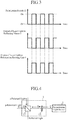
Fig. 3 is an explanatory drawing showing a relation between the on/off state of thepolarization switch 11, and the intensity in each output direction of the laser light beam. - It can be seen from
Fig. 3 that, when thepolarization switch 11 is off, the laser light beam is outputted from thepolarizer 12 of thepolarization changing unit 2 to the reflectingmirror 3, whereas when thepolarization switch 11 is on, the laser light beam is outputted from thepolarizer 12 of thepolarization changing unit 2 to thepolarization rotating unit 6. - Therefore, by switching between the on and off states of the
polarization switch 11, the eye direction can be changed. - Here, Figure of Merit (FOM) showing the performance index of a laser light transceiver, of which the number of eye directions is one, is expressed by the following equation (1), using the energy E of the laser light beam per pulse, and the repetitive frequency f of pulses.

- Therefore, in the laser light transceiver (Embodiments 1 and 2) which employs two eye directions and changes the polarization of the laser light beam with respect to time, FOM per eye direction is expressed by the following equation (2).

- In contrast with this, like in the case of the laser light transceiver described in
Patent Literature 2, in the case in which a polarization beam splitter splits the power of a laser light beam into two different directions and emits the laser light beams toward two eye directions simultaneously, FOM per eye direction is expressed by the following equation (3).
- As can be seen from a comparison between the equation (2) and the equation (3), FOM which can be acquired in the case of changing the polarization of a laser light beam with respect to time, like in the case of
Embodiments 1 and 2, is higher than that acquired in the case of splitting the power of a laser light beam into two different directions. - Accordingly, when FOM per eye direction is equalized in the aforementioned cases, the laser light transceiver according to any of
Embodiments 1 and 2 can reduce the power of the laser light beam which the transmission light source 1 is requested to output, as compared with the laser light transceiver described inPatent Literature 2. As a result, downsizing and weight reduction of the transmission light source 1 can be achieved and the power consumption of the laser light transceiver can be reduced, and the laser light transceiver can be reduced in size and weight. - Although the example in which the
polarization changing unit 2 which consists of thepolarization switch 11 and thepolarizer 12 changes the polarization of the laser light beam with respect to time is shown in thisEmbodiment 2, a 1/2wavelength plate 13 can be used, as shown inFig. 4 , instead of thepolarization switch 11 when the output power (energy) of the laser light beam emitted from each of the transmissionoptical systems - For example, by rotating the 1/2
wavelength plate 13 in such a way that the polarization direction forms an angle of 45 degrees with respect to thepolarizer 12 which is a polarization beam splitter, thepolarizer 12 splits the laser light beam outputted from the transmission light source 1 and passing through the 1/2wavelength plate 13 into laser light beams in two directions (outputs a p-polarized laser light beam to the reflectingmirror 3 and outputs an s-polarized laser light beam to the polarization rotating unit 6). - At this time, although the output power of the laser light beam is split into halves by the
polarizer 12 which is a polarization beam splitter, and the output power of each split laser light beam is reduced, the laser light beams can be emitted simultaneously toward the two eye directions. - Therefore, the reception
optical system 8 can receive reflected light beams from the two eye directions nearly simultaneously. - Further, because the polarization direction of a linearly-polarized laser light beam can be changed to any direction by using the 1/2
wavelength plate 13, the split ratio of laser light beams after splitting by thepolarizer 12 can be set freely. - When the rotation angle of the 1/2
wavelength plate 13 is made to change with respect to time in such a way that the polarization direction forms an angle of 0 degrees or 90 degrees with respect to thepolarizer 12, the polarization of the laser light beam can be changed with respect to time, like in the case of using thepolarization switch 11. - However, in this case, a mechanical mechanism for changing the rotation angle of the 1/2
wavelength plate 13 is needed. - Although the example of using the 1/2
wavelength plate 13 instead of thepolarization switch 11 is shown in this embodiment, when the laser light beam outputted from the transmission light source 1 is circularly polarized, a 1/4 wavelength plate can be used instead of thepolarization switch 11. In this case, the same effect as that produced by the 1/2wavelength plate 13 is produced. In this case, because the 1/4 wavelength plate can convert a circularly-polarized light beam into a linearly-polarized light beam having a discretionary polarization direction, the split ratio of laser light beams after splitting by thepolarizer 12 can be set freely. - As an alternative, an azimuth rotator for rotating the polarization direction of the laser light beam can be used instead of the
polarization switch 11, the same effect as that produced by the 1/2wavelength plate 13 is produced. -
Fig. 5 is a structural diagram showing a laser radar device according toEmbodiment 3 of the present invention. The laser radar device shown inFig. 5 includes a laser light transceiver shown inFig. 1 mounted therein. InFig. 5 , because the same reference numerals as those shown inFig. 1 denote the same components or similar components, the explanation of the components will be omitted hereafter. - A reflected light
beam switching unit 21 is comprised of, for example, a polarization coupler or a polarizer, and outputs each reflected light beam received by a reception optical system 8 (an s-polarized reflected light beam or a p-polarized reflected light beam) toward a direction corresponding to the polarization of the reflected light beam. - More specifically, the reflected light
beam switching unit 21 allows a p-polarized reflected light beam outputted from the receptionoptical system 8 to pass therethrough and outputs the p-polarized reflected light beam to anoptical combiner 23, and reflects an s-polarized reflected light beam outputted from the receptionoptical system 8 and outputs the s-polarized reflected light beam to anoptical combiner 25. The reflected lightbeam switching unit 21 constructs a reflected light beam switching means. - A
polarization switch 22 is comprised of, for example, a Pockels cell, a Kerr cell, a 1/2 wavelength plate equipped with a rotating means, or a waveguide type polarization switch, and outputs a local light beam corresponding to a laser light beam outputted from a transmission light source 1 (a light beam split from the laser light beam outputted from the transmission light source 1) toward a direction corresponding to the polarization of the local light beam while changing the polarization of the local light beam with respect to time. - More specifically, the
polarization switch 22 outputs a p-polarized local light beam outputted from the transmission light source 1 to theoptical combiner 23 without changing the polarization direction of the p-polarized local light beam, at the time of OFF, whereas thepolarization switch 22 changes the polarization of the p-polarized local light beam outputted from the transmission light source 1 to the s polarization by rotating the polarization direction of the local light beam by 90 degrees, and outputs the s-polarized local light beam to theoptical combiner 25, at the time of ON. Thepolarization switch 22 constructs a local light beam switching means. - The
optical combiner 23 is comprised of, for example, a 3dB coupler, a beam splitter, a partially reflecting mirror, etc., and optically combines the p-polarized reflected light beam outputted from the reflected lightbeam switching unit 21 and the p-polarized local light beam outputted from thepolarization switch 22, to generate a composite light beam, and outputs the composite light beam (a signal having a difference frequency between the reflected light beam and the local light beam) to anoptical detector 24. - The
optical detector 24 is comprised of, for example, a photo diode or a balanced receiver, and converts the composite light beam outputted from theoptical combiner 23 into an electric signal and outputs a beat signal which is the electric signal. - A first heterodyne detecting unit is comprised of the
optical combiner 23 and theoptical detector 24. - The
optical combiner 25 is comprised of, for example, a 3dB coupler, a beam splitter, a partially reflecting mirror, etc., and optically combines the s-polarized reflected light beam outputted from the reflected lightbeam switching unit 21 and the s-polarized local light beam outputted from thepolarization switch 22, to generate a composite light beam, and outputs the composite light beam (a signal having a difference frequency between the reflected light beam and the local light beam) to an optical detector 26. - The optical detector 26 is comprised of, for example, a photo diode or a balanced receiver, and converts the composite light beam outputted from the
optical combiner 25 into an electric signal and outputs a beat signal which is the electric signal. - A second heterodyne detecting unit is comprised of the
optical combiner 25 and the optical detector 26. - Further, a heterodyne detecting means is comprised of the reflected light
beam switching unit 21, thepolarization switch 22, theoptical combiners optical detectors 24 and 26. - Next, operations will be explained.
- When the reception
optical system 8 receives a reflected light beam (an s-polarized reflected light beam or a p-polarized reflected light beam), the reflected lightbeam switching unit 21 changes the output destination of the reflected light beam with respect to time in accordance with the polarization of the reflected light beam (the s-polarized reflected light beam or the p-polarized reflected light beam), in the same way that the laser light transceiver according to any of above-mentionedEmbodiments 1 and 2 does. - More specifically, when receiving a p-polarized reflected light beam from the reception
optical system 8, the reflected lightbeam switching unit 21 allows the p-polarized reflected light beam to pass therethrough and outputs the p-polarized reflected light beam to theoptical combiner 23. - In contrast, when receiving an s-polarized reflected light beam from the reception
optical system 8, the reflected lightbeam switching unit 21 reflects the s-polarized reflected light beam and outputs the s-polarized reflected light beam to theoptical combiner 25. - Because the polarization direction of the reflected light beam inputted from the reception
optical system 8 to the reflected lightbeam switching unit 21 changes with respect to time in accordance with the switching between OFF and ON of thepolarization switch 11, the output destination of the reflected light beam outputted from the reflected lightbeam switching unit 21 is switched with respect to time. - During a time period during which a
polarization changing unit 2 outputs a p-polarized laser light beam and acquires an s-polarized reflected light beam, thepolarization switch 22 enters the ON state, and, when then receiving a p-polarized local light beam from the transmission light source 1 (a light beam split from the p-polarized laser light beam), thepolarization switch 22 changes the polarization of the polarized local light beam from the p polarization to the s polarization by rotating the polarization direction of the p-polarized local light beam by 90 degrees and outputs the s-polarized local light beam to theoptical combiner 25. - Further, during a time period during which the
polarization changing unit 2 outputs an s-polarized laser light beam and acquires a p-polarized reflected light beam, thepolarization switch 22 enters the OFF state, and when then receiving a p-polarized local light beam from the transmission light source 1, thepolarization switch 22 outputs the p-polarized local light beam to theoptical combiner 23 without changing the polarization direction of the p-polarized local light beam. - The
polarization changing unit 2 and thepolarization switch 22 can be synchronized with each other in their operation timings. Further, a delay time can be provided for either of thepolarization changing unit 2 and thepolarization switch 22. By causing thepolarization changing unit 2 and thepolarization switch 22 to be synchronized with each other in their operation timings, the laser radar device can carry out heterodyne detection efficiently. As an alternative, by providing a delay time for either of the polarization changing unit and the polarization switch, the laser radar device can carry out heterodyne detection except in a transient state in which thepolarization changing unit 2 changes the polarization. - The
optical combiner 23 optically combines the p-polarized reflected light beam outputted from the reflected lightbeam switching unit 21 and the p-polarized local light beam outputted from thepolarization switch 22, to generate a composite light beam and outputs the composite light beam (a signal having a difference frequency between the reflected light beam and the local light beam) to theoptical detector 24. - When receiving the composite light beam from the
optical combiner 23, theoptical detector 24 converts the composite light beam into an electric signal and outputs a beat signal which is the electric signal. - The
optical combiner 25 optically combines the s-polarized reflected light beam outputted from the reflected lightbeam switching unit 21 and the s-polarized local light beam outputted from thepolarization switch 22, to generate a composite light beam, and outputs the composite light beam (a signal having a difference frequency between the reflected light beam and the local light beam) to the optical detector 26. - When receiving the composite light beam from the
optical combiner 25, the optical detector 26 converts the composite light beam into an electric signal and outputs a beat signal which is the electric signal. - The beat signals outputted from the
optical detectors 24 and 26 are inputted to a signal processor not illustrated, and the signal processor analyzes the frequency components of the beat signals, thereby calculating the moving speed (wind speed) of a target. Because the laser radar device emits laser light beams toward two eye directions, the laser radar device can carry out observations in the two eye directions and measure the direction of the wind in the plane including the two directions. - Further, the laser radar device can calculate the distance to a target from the time which has elapsed until the laser light transceiver emits a laser light beam and receives a reflected light beam. Because the laser radar device emits the laser light beams toward the two eye directions, the laser radar device can carry out observations in the two eye directions and calculate the direction of the wind in the plane including the two directions by performing an arithmetic operation or the like.
- As can be seen from the above description, because the laser radar device according to this
Embodiment 3 is configured so as to include thepolarization changing unit 2 to output a laser light beam toward a direction corresponding to the polarization of the laser light beam while changing the polarization of the laser light beam outputted from the transmission light source 1 with respect to time, there is provided an advantage of being able to transmit a laser light beam, whose power is not decreased, in two eye directions without mechanically scanning with the laser light beam, like in the case of above-mentionedEmbodiments 1 and 2. - Further, because the
polarization switch 22 according to thisEmbodiment 3 is configured so as to output a local light beam toward a direction corresponding to the polarization of the local light beam while changing the polarization of the local light beam split from the laser light beam outputted from the transmission light source 1 with respect to time, the laser radar device does not have to include a light source for the local light beam mounted therein. Therefore, there is provided an advantage of being able to downsize the laser radar device and also reduce the power consumption of the laser radar device. - Further, because the laser radar device according to this
Embodiment 3 is configured so as to change the polarization of the local light beam with respect to time by using thepolarization switch 22 and cause this polarization switch to output the local light beam toward the direction corresponding to the polarization of the local light beam, thereby causing the polarization direction of the local light beam to match that of the reflected light beam outputted from the receptionoptical system 8, the laser radar device can carry out heterodyne detection efficiently. Further, because the laser radar device can reduce the power of the local light beam which the transmission light source 1 is requested to output, there is provided an advantage of being able to downsize the laser radar device and also reduce the power consumption of the laser radar device. - In this
Embodiment 3, in the case in which some optical fiber type components are used, for example, in the case in which a polarization coupler is used as the reflected lightbeam switching unit 21, a waveguide type polarization switch is used as thepolarization switch 22, and 3dB couplers are used as theoptical combiners - Further, in the case in which balanced receivers are used as the
optical detectors 24 and 26, the laser radar device can carry out high-sensitivity detection while reducing the influence of noise. -
Fig. 6 is a structural diagram showing a laser radar device according toEmbodiment 4 of the present invention. InFig. 6 , because the same reference numerals as those shown inFig. 5 denote the same components or like components, the explanation of the components will be omitted hereafter. - A local
light splitting unit 27 is comprised of, for example, a polarization coupler, a polarization beam splitter, a thin film polarizer, a Polaroid plate, or a polarizer such a Glan-laser prism or a Wollaston prism, and splits a local light beam outputted from a transmission light source 1 (a light beam split from a laser light beam) into beams in two directions. In the case in which a polarizing coupler is used as the locallight splitting unit 27, the laser radar device can be configured using optical fibers. The locallight splitting unit 27 constructs a local light beam splitting means. - Although the example in which the
polarization switch 22 switches between its on and off states with respect to time, and outputs a p-polarized local light beam to theoptical combiner 23 at the time of OFF and outputs an s-polarized local light beam to theoptical combiner 25 at the time of ON is shown in above-mentionedEmbodiment 3, when receiving a local light beam from the transmission light source 1, the laser radar device can be configured in such a way that the locallight splitting unit 27 splits the local light beam into two beams, thereby outputting a p-polarized local light beam to anoptical combiner 23 and also outputting an s-polarized local light beam to anoptical combiner 25 at the same time, as explained inEmbodiment 4 shown inFig. 6 . - In the case in which a polarization coupler is used as the local
light splitting unit 27, the power of the local light beam outputted from the transmission light source 1 can be split into halves by simply causing the local light beam to enter the polarization coupler in such a way that the polarization of the local light beam is of a fifty-fifty mix of the p polarization and the s polarization. - By using the local
light splitting unit 27, instead of thepolarization switch 22, a cost reduction can be achieved and the reliability of the laser radar device can be improved, but the power of the local light beam has to be doubled. -
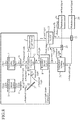
Fig. 7 is a structural diagram showing a laser radar device according toEmbodiment 5 of the present invention. InFig. 7 , because the same reference numerals as those shown inFig. 5 denote the same components or like components, the explanation of the components will be omitted hereafter. - A
polarization switch 28 is a polarization changing device comprised of, for example, a Pockels cell, a Kerr cell, a 1/2 wavelength plate equipped with a rotating means, or a waveguide type polarization switch, to change the polarization of a p-polarized local light beam outputted from a transmission light source 1 (a light beam split from a p-polarized laser light beam) with respect to time. - As a result, although the
polarization switch 28 alternately outputs a p-polarized local light beam and an s-polarized local light beam, like thepolarization switch 22 shown inFig. 5 , thepolarization switch 28 outputs the p-polarized local light beam and the s-polarized local light beam to an identicaloptical combiner 29 without changing the output destination between the p-polarized local light beam and the s-polarized local light beam, unlike thepolarization switch 22 shown inFig. 5 . Thepolarization switch 28 constructs a local light beam switching means. - The
optical combiner 29 is comprised of, for example, a 3dB coupler, a beam splitter, a partially reflecting mirror, etc., and optically combines a p-polarized reflected light beam outputted from a receptionoptical system 8 and the p-polarized local light beam outputted from thepolarization switch 28, to generate a composite light beam, and outputs the composite light beam to anoptical detector 30, and also optically combines an s-polarized reflected light beam outputted from the receptionoptical system 8 and the s-polarized local light beam outputted from thepolarization switch 28, to generate a composite light beam, and outputs the composite light beam to theoptical detector 30. - The
optical detector 30 is comprised of, for example, a photo diode or a balanced receiver, and converts the composite light beam outputted from theoptical combiner 29 into an electric signal and outputs a beat signal which is the electric signal. - A heterodyne detecting unit is comprised of the
optical combiner 29 and theoptical detector 30. - Further, a heterodyne detecting means is comprised of the
polarization switch 28, theoptical combiner 29 and theoptical detector 30. - Next, operations will be explained.
- The reception
optical system 8 receives an s-polarized reflected light beam which is reflected by apolarization changing unit 2 after being outputted from a reflectingmirror 3, like that according to any of above-mentioned Embodiments 1 to 4. The reception optical system also receives a p-polarized reflected light beam which passes through thepolarization changing unit 2 after being outputted from apolarization rotating unit 6. More specifically, the polarization direction of the reflected light beam received by the receptionoptical system 8 changes with respect to time. - The reception
optical system 8 outputs the received reflected light beam to theoptical combiner 29. - During a time period during which the
polarization changing unit 2 outputs a p-polarized laser light beam and acquires an s-polarized reflected light beam, thepolarization switch 28 enters the ON state, and, when then receiving a p-polarized local light beam from the transmission light source 1, changes the polarization of the local light beam from the p polarization to the s polarization by rotating the polarization direction of the p-polarized local light beam by 90 degrees, and outputs the s-polarized local light beam to theoptical combiner 29. - Further, during a time period during which the
polarization changing unit 2 outputs an s-polarized laser light beam and acquires a p-polarized reflected light beam, thepolarization switch 28 enters the OFF state, and, when then receiving a p-polarized local light beam from the transmission light source 1, outputs the p-polarized local light beam to theoptical combiner 29 without changing the polarization of the p-polarized local light beam. - Because the timing of changing the polarization of the laser light beam in the
polarization changing unit 2 is synchronized with the timing of changing the polarization of the laser light beam in thepolarization switch 28, the s-polarized local light beam is outputted from thepolarization switch 28 to theoptical combiner 29 at the time when the s-polarized reflected light beam is outputted from the receptionoptical system 8 to theoptical combiner 29. Further, the p-polarized local light beam is outputted from thepolarization switch 28 to theoptical combiner 29 at the time when the p-polarized reflected light beam is outputted from the receptionoptical system 8 to theoptical combiner 29. - The
optical combiner 29 optically combines the p-polarized reflected light beam outputted from the receptionoptical system 8 and the p-polarized local light beam outputted from thepolarization switch 28, to generate a composite light beam, and outputs the composite light beam to theoptical detector 30. - Further, the
optical combiner 29 optically combines the s-polarized reflected light beam outputted from the receptionoptical system 8 and the s-polarized local light beam outputted from thepolarization switch 28, to generate a composite light beam, and outputs the composite light beam to theoptical detector 30. - When receiving each of the composite light beams from the
optical combiner 29, theoptical detector 30 converts the composite light beam into an electric signal, and outputs a beat signal which is the electric signal. - Although this
Embodiment 5 can provide the same advantages as those provided by any of above-mentionedEmbodiments beam switching unit 21 become unnecessary and, by using a single heterodyne detecting unit, the laser radar device can be configured. - The
polarization switch 28 can be alternatively disposed on a route from the receptionoptical system 8 to theoptical combiner 29, and can be configured so as to change the polarization direction of a reflected light beam received thereby. However, because a loss occurs in the received light beam, it is desirable to dispose the polarization switch on the route of the local light beam when the power of the local light beam has a margin. - Although the example in which the polarization direction of the reflected light beam received by the reception
optical system 8 changes with respect to time is shown in above-mentionedEmbodiments 3 to 5, the receptionoptical system 8 receives an s-polarized reflected light beam and a p-polarized reflected light beam nearly simultaneously in the case in which a 1/2wavelength plate 13, a 1/4 wavelength plate, or the like is used instead of thepolarization switch 11 which constructs thepolarization changing unit 2, as shown inFig. 4 . - In this case, as shown in
Fig. 8 , the laser radar device can be configured so as to include, instead of the reflected lightbeam switching unit 21, apolarization splitting unit 31 to output an s-polarized reflected light beam and a p-polarized reflected light beam received by the receptionoptical system 8 in a splitting manner (a polarization splitting unit to output the p-polarized reflected light beam to anoptical combiner 23 and output the s-polarized reflected light beam to an optical combiner 23). - In addition, also in a
polarization switch 22, by using a 1/2wavelength plate 13, a 1/4 wavelength plate, or the like, an s-polarized local light beam and a p-polarized local light beam are outputted simultaneously. As a result, the laser radar device can simultaneously carry out heterodyne detection on reflected light beams from two eye directions, and can simultaneously carry out observations in the two eye directions. - While the invention has been described in its preferred embodiments, it is to be understood that any combination of two or more of the above-mentioned embodiments can be made, various changes can be made in any component in accordance with any one of the above-mentioned embodiments, and any component in accordance with any one of the above-mentioned embodiments can be omitted within the scope of the invention.
- The laser light transceiver and the laser radar device according to the present invention are suitable for devices that need to carry out observations in two eye directions.
- 1 transmission light source, 2 polarization changing unit (polarization changing means), 3 reflecting mirror (first transmission and reception optical system), 4 polarization rotating unit (first transmission and reception optical system), 5 transmission optical system (first transmission and reception optical system), 6 polarization rotating unit (second transmission and reception optical system), 7 transmission optical system (second transmission and reception optical system), 8 reception optical system, 11 polarization switch, 12 polarizer, 13 1/2 wavelength plate, 21 reflected light beam switching unit (reflected light beam switching unit, heterodyne detecting means), 22 polarization switch (local light beam switching means, heterodyne detecting means), 23 optical combiner (first heterodyne detecting unit, heterodyne detecting means), 24 optical detector (first heterodyne detecting unit, heterodyne detecting means), 25 optical combiner (second heterodyne detecting unit, heterodyne detecting means), 26 optical detector (second heterodyne detecting unit, heterodyne detecting means), 27 local light splitting unit (local light beam splitting unit, heterodyne detecting means), 28 polarization switch (local light beam switching means, heterodyne detecting means), 29 optical combiner (heterodyne detecting unit, heterodyne detecting means), 30 optical detector (heterodyne detecting unit, heterodyne detecting means), and 31 polarization splitting unit.
Claims (7)
- A laser light transceiver comprising:a light source for outputting a laser light beam;a polarization changing means for outputting said laser light beam toward a direction corresponding to polarization of said laser light beam while changing the polarization of said laser light beam outputted from said light source with respect to time;a first transmission and reception optical system for emitting the laser light beam outputted from said polarization changing means into space, and receiving a reflected light beam of said laser light beam, the reflected light beam being reflected by an observation target existing in the space;a second transmission and reception optical system disposed in a direction different from that in which said first transmission and reception optical system is disposed, for emitting the laser light beam outputted from said polarization changing means into the space, and receiving a reflected light beam of said laser light beam, the reflected light beam being reflected by an observation target existing in the space; anda reception optical system for receiving the reflected light beam received by said first transmission and reception optical system, and also receiving the reflected light beam received by said second transmission and reception optical system.
- The laser light transceiver according to claim 1, wherein said polarization changing means comprises a polarization changing device for changing the polarization of the laser light beam outputted from said light source with respect to time, and a polarizer for outputting said laser light beam to either said first transmission and reception optical system or said second transmission and reception optical system in accordance with the polarization changed by said polarization changing device.
- The laser light transceiver according to claim 2, wherein said polarizer reflects the reflected light beams received by said first and second transmission and reception optical systems toward a direction in which said reception optical system is disposed.
- A laser radar device comprising:a light source for outputting a laser light beam;a polarization changing means for outputting said laser light beam toward a direction corresponding to polarization of said laser light beam while changing the polarization of said laser light beam outputted from said light source with respect to time;a first transmission and reception optical system for emitting the laser light beam outputted from said polarization changing means into space, and receiving a reflected light beam of said laser light beam, the reflected light beam being reflected by an observation target existing in the space;a second transmission and reception optical system disposed in a direction different from that in which said first transmission and reception optical system is disposed, for emitting the laser light beam outputted from said polarization changing means into the space, and receiving a reflected light beam of said laser light beam, the reflected light beam being reflected by an observation target existing in the space;a reception optical system for receiving the reflected light beam received by said first transmission and reception optical system, and also receiving the reflected light beam received by said second transmission and reception optical system; anda heterodyne detecting means for combining each of the reflected light beams received by said reception optical system, and a local light beam corresponding to the laser light beam outputted from said light source, to acquire beat signals.
- The laser radar device according to claim 4, wherein said heterodyne detecting means includes:a reflected light beam switching means for outputting the reflected light beams received by said reception optical system toward directions corresponding to polarization directions of said reflected light beams;a local light beam switching means for outputting the local light beam corresponding to the laser light beam toward a direction corresponding to polarization of said local light beam while changing the polarization of said local light beam outputted from said light source with respect to time;a first heterodyne detecting unit for combining one of the reflected light beams outputted from said reflected light beam switching means and the local light beam outputted from said local light beam switching means, to acquire a beat signal; anda second heterodyne detecting unit disposed in a direction different from that in which said first heterodyne detecting unit is disposed, for combining another of the reflected light beams outputted from said reflected light beam switching means and the local light beam outputted from said local light beam switching means, to acquire a beat signal.
- The laser radar device according to claim 4, wherein said heterodyne detecting means includes:a reflected light beam switching means for outputting the reflected light beams received by said reception optical system toward directions corresponding to polarization directions of said reflected light beams;a local light beam splitting unit for splitting the local light beam corresponding to the laser light beam outputted from said light source into beams in two directions;a first heterodyne detecting unit for combining one of the reflected light beams outputted from said reflected light beam switching means and a local light beam which is one of the beams split by said local light beam splitting unit, to acquire a beat signal; anda second heterodyne detecting unit for combining another of the reflected light beams outputted from said reflected light beam switching means and a local light beam which is another of the beams split by said local light beam splitting unit, to acquire a beat signal.
- The laser radar device according to claim 4, wherein said heterodyne detecting means includes:a local light beam switching means for changing polarization of the local light beam corresponding to the laser light beam outputted from said light source with respect to time; anda heterodyne detector for combining each of the reflected light beams received by said reception optical system and the local light beam whose polarization is changed with respect to time by said local light beam switching means, to acquire beat signals.
Applications Claiming Priority (1)
| Application Number | Priority Date | Filing Date | Title |
|---|---|---|---|
| PCT/JP2014/071315 WO2016024332A1 (en) | 2014-08-12 | 2014-08-12 | Laser light sending and receiving device and laser radar device |
Publications (3)
| Publication Number | Publication Date |
|---|---|
| EP3182152A1 true EP3182152A1 (en) | 2017-06-21 |
| EP3182152A4 EP3182152A4 (en) | 2017-08-30 |
| EP3182152B1 EP3182152B1 (en) | 2019-05-15 |
Family
ID=55303976
Family Applications (1)
| Application Number | Title | Priority Date | Filing Date |
|---|---|---|---|
| EP14899693.7A Active EP3182152B1 (en) | 2014-08-12 | 2014-08-12 | Laser light sending and receiving device and laser radar device |
Country Status (5)
| Country | Link |
|---|---|
| US (1) | US10353054B2 (en) |
| EP (1) | EP3182152B1 (en) |
| JP (1) | JP6293285B2 (en) |
| CN (1) | CN106574963B (en) |
| WO (1) | WO2016024332A1 (en) |
Cited By (2)
| Publication number | Priority date | Publication date | Assignee | Title |
|---|---|---|---|---|
| DE102017210591A1 (en) * | 2017-06-23 | 2018-12-27 | Robert Bosch Gmbh | Macroscopic lidar device |
| DE112018007552B4 (en) | 2018-06-12 | 2022-03-10 | Mitsubishi Electric Corporation | Optical distance measuring device and processing device |
Families Citing this family (22)
| Publication number | Priority date | Publication date | Assignee | Title |
|---|---|---|---|---|
| US20110187878A1 (en) | 2010-02-02 | 2011-08-04 | Primesense Ltd. | Synchronization of projected illumination with rolling shutter of image sensor |
| JP6513846B2 (en) * | 2017-06-06 | 2019-05-15 | 株式会社日立製作所 | Distance measuring device and three-dimensional shape measuring device. |
| WO2018225496A1 (en) * | 2017-06-06 | 2018-12-13 | 株式会社日立製作所 | Distance measurement device and three-dimensional-shape measurement device |
| US10816649B1 (en) * | 2017-09-14 | 2020-10-27 | The United States Of America As Represented By The Secretary Of The Air Force | Temporally multiplexed LADAR polarimeter |
| US10447424B2 (en) | 2018-01-18 | 2019-10-15 | Apple Inc. | Spatial multiplexing scheme |
| KR102611985B1 (en) | 2018-01-24 | 2023-12-08 | 삼성전자주식회사 | optical integrated circuit device array having bi-directional characteristics and optical system using the same |
| US11022683B1 (en) | 2018-03-15 | 2021-06-01 | Aeva, Inc. | Simultaneous measurement of range and velocity using optical radar |
| US10877285B2 (en) | 2018-03-28 | 2020-12-29 | Apple Inc. | Wavelength-based spatial multiplexing scheme |
| WO2019244242A1 (en) | 2018-06-19 | 2019-12-26 | 三菱電機株式会社 | Optical distance measurement device and processing device |
| JP6979391B2 (en) * | 2018-07-11 | 2021-12-15 | 株式会社日立製作所 | Distance measuring device, distance measuring method, and three-dimensional shape measuring device |
| CN108802756B (en) * | 2018-08-09 | 2021-07-13 | 常州信息职业技术学院 | All-fiber laser Doppler velocity measurement system based on acousto-optic zero coupler |
| US11493606B1 (en) | 2018-09-12 | 2022-11-08 | Apple Inc. | Multi-beam scanning system |
| EP3834002A2 (en) * | 2018-11-09 | 2021-06-16 | The Charles Stark Draper Laboratory, Inc. | Dual-polarization lidar systems and methods |
| CN109991614B (en) * | 2019-03-27 | 2021-02-05 | 深圳市速腾聚创科技有限公司 | Laser radar range unit |
| JP6954494B2 (en) * | 2019-04-22 | 2021-10-27 | 三菱電機株式会社 | Laser radar device |
| CN110568420B (en) * | 2019-08-29 | 2021-06-11 | 北京空间机电研究所 | Laser radar receiving and transmitting alignment device and method |
| US11635502B2 (en) | 2020-09-24 | 2023-04-25 | Uatc, Llc | Light detection and ranging (LIDAR) system having a polarizing beam splitter |
| WO2022036127A1 (en) * | 2020-08-12 | 2022-02-17 | Uatc, Llc | Light detection and ranging (lidar) system having a polarizing beam splitter |
| US11435454B2 (en) | 2020-09-04 | 2022-09-06 | Ours Technology, Llc | Beam walkoff mitigation for light detection and ranging |
| WO2023225284A1 (en) * | 2022-05-20 | 2023-11-23 | Ours Technology, Llc | Lidar with switchable local oscillator signals |
| CN114740641B (en) * | 2022-06-09 | 2022-11-22 | 成都凯天电子股份有限公司 | Ultraviolet light switch and laser scanning system formed by same |
| CN115808245B (en) * | 2023-02-09 | 2023-06-02 | 青岛镭测创芯科技有限公司 | Polarized laser radar system |
Family Cites Families (15)
| Publication number | Priority date | Publication date | Assignee | Title |
|---|---|---|---|---|
| DE3886966T2 (en) | 1987-03-20 | 1994-08-18 | Digital Optronics Corp | Image system in three dimensions with coherent optical detection. |
| JPH10103918A (en) | 1996-09-27 | 1998-04-24 | Tokyo Seimitsu Co Ltd | Laser length-measuring apparatus |
| US5900975A (en) * | 1997-10-30 | 1999-05-04 | Cognex Corporation | Ghost image extinction in an active range sensor |
| US20020109829A1 (en) * | 1999-10-28 | 2002-08-15 | Hayes Cecil L. | Single aperture, alignment insensitive ladar system |
| JP2004285858A (en) | 2003-03-19 | 2004-10-14 | Mitsubishi Electric Corp | Wind power generation system and control method thereof |
| ITRM20040291A1 (en) * | 2004-06-16 | 2004-09-16 | Alenia Spazio Spa | BEAM SEPARATION APPARATUS FOR MONOSTATIC LIDARS. |
| JP4794250B2 (en) * | 2005-09-20 | 2011-10-19 | 三菱電機株式会社 | Laser radar equipment |
| JP4974773B2 (en) * | 2007-06-13 | 2012-07-11 | 三菱電機株式会社 | Lightwave radar device |
| FR2953934B1 (en) * | 2009-12-11 | 2011-12-09 | Thales Sa | OPTICAL ANEMOMETRIC PROBE WITH TWO AXIS OF MEASUREMENT |
| CN101825711A (en) * | 2009-12-24 | 2010-09-08 | 哈尔滨工业大学 | 2 mu m all-fiber coherent laser Doppler wind finding radar system |
| US8054464B2 (en) * | 2010-01-25 | 2011-11-08 | Sigma Space Corp. | Polarization switching lidar device and method |
| JP5885673B2 (en) | 2011-01-18 | 2016-03-15 | オリンパス株式会社 | Optical scanning device and scanning inspection device |
| FR2972879B1 (en) * | 2011-03-14 | 2014-02-21 | Upwind | TRANSMITTING AND RECEIVING DEVICE, REMOTE SENSING SYSTEM AND METHOD OF TRANSMITTING AND RECEIVING THEREOF. |
| CN102426027B (en) * | 2011-09-05 | 2013-10-02 | 南京德朔实业有限公司 | Inner optical system control and switching apparatus for laser range finder |
| EP2828687B1 (en) * | 2012-03-23 | 2020-08-05 | Windar Photonics A/S | Multiple directional lidar system |
-
2014
- 2014-08-12 EP EP14899693.7A patent/EP3182152B1/en active Active
- 2014-08-12 US US15/502,750 patent/US10353054B2/en active Active
- 2014-08-12 WO PCT/JP2014/071315 patent/WO2016024332A1/en active Application Filing
- 2014-08-12 CN CN201480080994.0A patent/CN106574963B/en active Active
- 2014-08-12 JP JP2016542465A patent/JP6293285B2/en active Active
Cited By (3)
| Publication number | Priority date | Publication date | Assignee | Title |
|---|---|---|---|---|
| DE102017210591A1 (en) * | 2017-06-23 | 2018-12-27 | Robert Bosch Gmbh | Macroscopic lidar device |
| DE112018007552B4 (en) | 2018-06-12 | 2022-03-10 | Mitsubishi Electric Corporation | Optical distance measuring device and processing device |
| US11977157B2 (en) | 2018-06-12 | 2024-05-07 | Mitsubishi Electric Corporation | Optical distance measurement device and machining device |
Also Published As
| Publication number | Publication date |
|---|---|
| JP6293285B2 (en) | 2018-03-14 |
| JPWO2016024332A1 (en) | 2017-04-27 |
| CN106574963B (en) | 2018-03-06 |
| EP3182152A4 (en) | 2017-08-30 |
| US20170242100A1 (en) | 2017-08-24 |
| US10353054B2 (en) | 2019-07-16 |
| WO2016024332A1 (en) | 2016-02-18 |
| EP3182152B1 (en) | 2019-05-15 |
| CN106574963A (en) | 2017-04-19 |
Similar Documents
| Publication | Publication Date | Title |
|---|---|---|
| EP3182152B1 (en) | Laser light sending and receiving device and laser radar device | |
| CN110646776B (en) | Chip-scale LIDAR with a single MEMS scanner in a compact optical package | |
| JP6072301B2 (en) | Laser radar equipment | |
| US11047983B1 (en) | Coherent LiDAR system utilizing a non-reciprocal optical element | |
| CN107367734B (en) | Measuring device | |
| US20200124711A1 (en) | Descan compensation in scanning lidar | |
| US5510890A (en) | Laser radar with reference beam storage | |
| JP4974773B2 (en) | Lightwave radar device | |
| CN113841062B (en) | LIDAR system with mode field expander | |
| US20150185246A1 (en) | Laser Doppler Velocimeter With Intelligent Optical Device | |
| CN113167865B (en) | Polarization encoded beam transmission and collection | |
| US7800755B1 (en) | High-speed polarimeter having a multi-wavelength source | |
| CN115542345A (en) | FMCW laser radar, automatic driving system and movable equipment | |
| CN102780153B (en) | Acousto-optic frequency sweeping laser based on acousto-optic deflection device | |
| CN109444848B (en) | Scanning device and scanning method thereof, and laser radar | |
| CN115291194A (en) | Light receiving and dispatching module, laser radar, automatic driving system and movable equipment | |
| CN114460601A (en) | Laser radar system | |
| JP2003307567A (en) | Coherent laser radar device | |
| CN218782406U (en) | Coherent wind measurement laser radar system | |
| US20230314611A1 (en) | Techniques for equalizing powers of multiple local oscillator beams using optical attenuators | |
| US20220276514A1 (en) | Optical testing apparatus | |
| US11698444B1 (en) | Techniques for enhancing LO and RX overlap in FMCW lidars using birefringent crystals | |
| JP2008191037A (en) | Laser radar device | |
| CN116068584A (en) | Non-blind area coherent laser radar | |
| JPH02253239A (en) | Acousto optical switch |
Legal Events
| Date | Code | Title | Description |
|---|---|---|---|
| STAA | Information on the status of an ep patent application or granted ep patent |
Free format text: STATUS: THE INTERNATIONAL PUBLICATION HAS BEEN MADE |
|
| PUAI | Public reference made under article 153(3) epc to a published international application that has entered the european phase |
Free format text: ORIGINAL CODE: 0009012 |
|
| STAA | Information on the status of an ep patent application or granted ep patent |
Free format text: STATUS: REQUEST FOR EXAMINATION WAS MADE |
|
| 17P | Request for examination filed |
Effective date: 20170309 |
|
| AK | Designated contracting states |
Kind code of ref document: A1 Designated state(s): AL AT BE BG CH CY CZ DE DK EE ES FI FR GB GR HR HU IE IS IT LI LT LU LV MC MK MT NL NO PL PT RO RS SE SI SK SM TR |
|
| AX | Request for extension of the european patent |
Extension state: BA ME |
|
| REG | Reference to a national code |
Ref country code: DE Ref legal event code: R079 Ref document number: 602014047049 Country of ref document: DE Free format text: PREVIOUS MAIN CLASS: G01S0007481000 Ipc: G01S0017580000 |
|
| A4 | Supplementary search report drawn up and despatched |
Effective date: 20170802 |
|
| RIC1 | Information provided on ipc code assigned before grant |
Ipc: G01S 7/491 20060101ALI20170727BHEP Ipc: G01C 3/06 20060101ALI20170727BHEP Ipc: G01S 7/481 20060101ALI20170727BHEP Ipc: G01S 7/499 20060101ALI20170727BHEP Ipc: G01S 17/58 20060101AFI20170727BHEP Ipc: G01S 17/95 20060101ALI20170727BHEP |
|
| DAX | Request for extension of the european patent (deleted) | ||
| STAA | Information on the status of an ep patent application or granted ep patent |
Free format text: STATUS: EXAMINATION IS IN PROGRESS |
|
| 17Q | First examination report despatched |
Effective date: 20180511 |
|
| GRAP | Despatch of communication of intention to grant a patent |
Free format text: ORIGINAL CODE: EPIDOSNIGR1 |
|
| STAA | Information on the status of an ep patent application or granted ep patent |
Free format text: STATUS: GRANT OF PATENT IS INTENDED |
|
| INTG | Intention to grant announced |
Effective date: 20181204 |
|
| RIN1 | Information on inventor provided before grant (corrected) |
Inventor name: YANAGISAWA, TAKAYUKI Inventor name: AKINO, YOSUKE Inventor name: SAKIMURA, TAKESHI Inventor name: TANAKA, HISAMICHI Inventor name: HINOKUMA, YASUHIRO |
|
| GRAS | Grant fee paid |
Free format text: ORIGINAL CODE: EPIDOSNIGR3 |
|
| GRAA | (expected) grant |
Free format text: ORIGINAL CODE: 0009210 |
|
| STAA | Information on the status of an ep patent application or granted ep patent |
Free format text: STATUS: THE PATENT HAS BEEN GRANTED |
|
| AK | Designated contracting states |
Kind code of ref document: B1 Designated state(s): AL AT BE BG CH CY CZ DE DK EE ES FI FR GB GR HR HU IE IS IT LI LT LU LV MC MK MT NL NO PL PT RO RS SE SI SK SM TR |
|
| REG | Reference to a national code |
Ref country code: CH Ref legal event code: EP |
|
| REG | Reference to a national code |
Ref country code: IE Ref legal event code: FG4D |
|
| REG | Reference to a national code |
Ref country code: DE Ref legal event code: R096 Ref document number: 602014047049 Country of ref document: DE |
|
| REG | Reference to a national code |
Ref country code: NL Ref legal event code: MP Effective date: 20190515 |
|
| REG | Reference to a national code |
Ref country code: LT Ref legal event code: MG4D |
|
| PG25 | Lapsed in a contracting state [announced via postgrant information from national office to epo] |
Ref country code: LT Free format text: LAPSE BECAUSE OF FAILURE TO SUBMIT A TRANSLATION OF THE DESCRIPTION OR TO PAY THE FEE WITHIN THE PRESCRIBED TIME-LIMIT Effective date: 20190515 Ref country code: NO Free format text: LAPSE BECAUSE OF FAILURE TO SUBMIT A TRANSLATION OF THE DESCRIPTION OR TO PAY THE FEE WITHIN THE PRESCRIBED TIME-LIMIT Effective date: 20190815 Ref country code: FI Free format text: LAPSE BECAUSE OF FAILURE TO SUBMIT A TRANSLATION OF THE DESCRIPTION OR TO PAY THE FEE WITHIN THE PRESCRIBED TIME-LIMIT Effective date: 20190515 Ref country code: NL Free format text: LAPSE BECAUSE OF FAILURE TO SUBMIT A TRANSLATION OF THE DESCRIPTION OR TO PAY THE FEE WITHIN THE PRESCRIBED TIME-LIMIT Effective date: 20190515 Ref country code: PT Free format text: LAPSE BECAUSE OF FAILURE TO SUBMIT A TRANSLATION OF THE DESCRIPTION OR TO PAY THE FEE WITHIN THE PRESCRIBED TIME-LIMIT Effective date: 20190915 Ref country code: AL Free format text: LAPSE BECAUSE OF FAILURE TO SUBMIT A TRANSLATION OF THE DESCRIPTION OR TO PAY THE FEE WITHIN THE PRESCRIBED TIME-LIMIT Effective date: 20190515 Ref country code: ES Free format text: LAPSE BECAUSE OF FAILURE TO SUBMIT A TRANSLATION OF THE DESCRIPTION OR TO PAY THE FEE WITHIN THE PRESCRIBED TIME-LIMIT Effective date: 20190515 Ref country code: SE Free format text: LAPSE BECAUSE OF FAILURE TO SUBMIT A TRANSLATION OF THE DESCRIPTION OR TO PAY THE FEE WITHIN THE PRESCRIBED TIME-LIMIT Effective date: 20190515 Ref country code: HR Free format text: LAPSE BECAUSE OF FAILURE TO SUBMIT A TRANSLATION OF THE DESCRIPTION OR TO PAY THE FEE WITHIN THE PRESCRIBED TIME-LIMIT Effective date: 20190515 |
|
| PG25 | Lapsed in a contracting state [announced via postgrant information from national office to epo] |
Ref country code: GR Free format text: LAPSE BECAUSE OF FAILURE TO SUBMIT A TRANSLATION OF THE DESCRIPTION OR TO PAY THE FEE WITHIN THE PRESCRIBED TIME-LIMIT Effective date: 20190816 Ref country code: LV Free format text: LAPSE BECAUSE OF FAILURE TO SUBMIT A TRANSLATION OF THE DESCRIPTION OR TO PAY THE FEE WITHIN THE PRESCRIBED TIME-LIMIT Effective date: 20190515 Ref country code: BG Free format text: LAPSE BECAUSE OF FAILURE TO SUBMIT A TRANSLATION OF THE DESCRIPTION OR TO PAY THE FEE WITHIN THE PRESCRIBED TIME-LIMIT Effective date: 20190815 Ref country code: RS Free format text: LAPSE BECAUSE OF FAILURE TO SUBMIT A TRANSLATION OF THE DESCRIPTION OR TO PAY THE FEE WITHIN THE PRESCRIBED TIME-LIMIT Effective date: 20190515 |
|
| REG | Reference to a national code |
Ref country code: AT Ref legal event code: MK05 Ref document number: 1134093 Country of ref document: AT Kind code of ref document: T Effective date: 20190515 |
|
| PG25 | Lapsed in a contracting state [announced via postgrant information from national office to epo] |
Ref country code: EE Free format text: LAPSE BECAUSE OF FAILURE TO SUBMIT A TRANSLATION OF THE DESCRIPTION OR TO PAY THE FEE WITHIN THE PRESCRIBED TIME-LIMIT Effective date: 20190515 Ref country code: AT Free format text: LAPSE BECAUSE OF FAILURE TO SUBMIT A TRANSLATION OF THE DESCRIPTION OR TO PAY THE FEE WITHIN THE PRESCRIBED TIME-LIMIT Effective date: 20190515 Ref country code: CZ Free format text: LAPSE BECAUSE OF FAILURE TO SUBMIT A TRANSLATION OF THE DESCRIPTION OR TO PAY THE FEE WITHIN THE PRESCRIBED TIME-LIMIT Effective date: 20190515 Ref country code: RO Free format text: LAPSE BECAUSE OF FAILURE TO SUBMIT A TRANSLATION OF THE DESCRIPTION OR TO PAY THE FEE WITHIN THE PRESCRIBED TIME-LIMIT Effective date: 20190515 Ref country code: DK Free format text: LAPSE BECAUSE OF FAILURE TO SUBMIT A TRANSLATION OF THE DESCRIPTION OR TO PAY THE FEE WITHIN THE PRESCRIBED TIME-LIMIT Effective date: 20190515 Ref country code: SK Free format text: LAPSE BECAUSE OF FAILURE TO SUBMIT A TRANSLATION OF THE DESCRIPTION OR TO PAY THE FEE WITHIN THE PRESCRIBED TIME-LIMIT Effective date: 20190515 |
|
| REG | Reference to a national code |
Ref country code: DE Ref legal event code: R097 Ref document number: 602014047049 Country of ref document: DE |
|
| PG25 | Lapsed in a contracting state [announced via postgrant information from national office to epo] |
Ref country code: SM Free format text: LAPSE BECAUSE OF FAILURE TO SUBMIT A TRANSLATION OF THE DESCRIPTION OR TO PAY THE FEE WITHIN THE PRESCRIBED TIME-LIMIT Effective date: 20190515 Ref country code: IT Free format text: LAPSE BECAUSE OF FAILURE TO SUBMIT A TRANSLATION OF THE DESCRIPTION OR TO PAY THE FEE WITHIN THE PRESCRIBED TIME-LIMIT Effective date: 20190515 |
|
| PLBE | No opposition filed within time limit |
Free format text: ORIGINAL CODE: 0009261 |
|
| STAA | Information on the status of an ep patent application or granted ep patent |
Free format text: STATUS: NO OPPOSITION FILED WITHIN TIME LIMIT |
|
| PG25 | Lapsed in a contracting state [announced via postgrant information from national office to epo] |
Ref country code: TR Free format text: LAPSE BECAUSE OF FAILURE TO SUBMIT A TRANSLATION OF THE DESCRIPTION OR TO PAY THE FEE WITHIN THE PRESCRIBED TIME-LIMIT Effective date: 20190515 |
|
| 26N | No opposition filed |
Effective date: 20200218 |
|
| PG25 | Lapsed in a contracting state [announced via postgrant information from national office to epo] |
Ref country code: PL Free format text: LAPSE BECAUSE OF FAILURE TO SUBMIT A TRANSLATION OF THE DESCRIPTION OR TO PAY THE FEE WITHIN THE PRESCRIBED TIME-LIMIT Effective date: 20190515 |
|
| PG25 | Lapsed in a contracting state [announced via postgrant information from national office to epo] |
Ref country code: CH Free format text: LAPSE BECAUSE OF NON-PAYMENT OF DUE FEES Effective date: 20190831 Ref country code: LI Free format text: LAPSE BECAUSE OF NON-PAYMENT OF DUE FEES Effective date: 20190831 Ref country code: MC Free format text: LAPSE BECAUSE OF FAILURE TO SUBMIT A TRANSLATION OF THE DESCRIPTION OR TO PAY THE FEE WITHIN THE PRESCRIBED TIME-LIMIT Effective date: 20190515 Ref country code: SI Free format text: LAPSE BECAUSE OF FAILURE TO SUBMIT A TRANSLATION OF THE DESCRIPTION OR TO PAY THE FEE WITHIN THE PRESCRIBED TIME-LIMIT Effective date: 20190515 Ref country code: LU Free format text: LAPSE BECAUSE OF NON-PAYMENT OF DUE FEES Effective date: 20190812 |
|
| REG | Reference to a national code |
Ref country code: BE Ref legal event code: MM Effective date: 20190831 |
|
| PG25 | Lapsed in a contracting state [announced via postgrant information from national office to epo] |
Ref country code: IE Free format text: LAPSE BECAUSE OF NON-PAYMENT OF DUE FEES Effective date: 20190812 |
|
| PG25 | Lapsed in a contracting state [announced via postgrant information from national office to epo] |
Ref country code: BE Free format text: LAPSE BECAUSE OF NON-PAYMENT OF DUE FEES Effective date: 20190831 |
|
| PG25 | Lapsed in a contracting state [announced via postgrant information from national office to epo] |
Ref country code: CY Free format text: LAPSE BECAUSE OF FAILURE TO SUBMIT A TRANSLATION OF THE DESCRIPTION OR TO PAY THE FEE WITHIN THE PRESCRIBED TIME-LIMIT Effective date: 20190515 |
|
| PG25 | Lapsed in a contracting state [announced via postgrant information from national office to epo] |
Ref country code: IS Free format text: LAPSE BECAUSE OF FAILURE TO SUBMIT A TRANSLATION OF THE DESCRIPTION OR TO PAY THE FEE WITHIN THE PRESCRIBED TIME-LIMIT Effective date: 20190915 |
|
| PG25 | Lapsed in a contracting state [announced via postgrant information from national office to epo] |
Ref country code: HU Free format text: LAPSE BECAUSE OF FAILURE TO SUBMIT A TRANSLATION OF THE DESCRIPTION OR TO PAY THE FEE WITHIN THE PRESCRIBED TIME-LIMIT; INVALID AB INITIO Effective date: 20140812 Ref country code: MT Free format text: LAPSE BECAUSE OF FAILURE TO SUBMIT A TRANSLATION OF THE DESCRIPTION OR TO PAY THE FEE WITHIN THE PRESCRIBED TIME-LIMIT Effective date: 20190515 |
|
| REG | Reference to a national code |
Ref country code: DE Ref legal event code: R084 Ref document number: 602014047049 Country of ref document: DE |
|
| REG | Reference to a national code |
Ref country code: GB Ref legal event code: 746 Effective date: 20220509 |
|
| PG25 | Lapsed in a contracting state [announced via postgrant information from national office to epo] |
Ref country code: MK Free format text: LAPSE BECAUSE OF FAILURE TO SUBMIT A TRANSLATION OF THE DESCRIPTION OR TO PAY THE FEE WITHIN THE PRESCRIBED TIME-LIMIT Effective date: 20190515 |
|
| P01 | Opt-out of the competence of the unified patent court (upc) registered |
Effective date: 20230512 |
|
| PGFP | Annual fee paid to national office [announced via postgrant information from national office to epo] |
Ref country code: GB Payment date: 20230629 Year of fee payment: 10 |
|
| PGFP | Annual fee paid to national office [announced via postgrant information from national office to epo] |
Ref country code: FR Payment date: 20230703 Year of fee payment: 10 Ref country code: DE Payment date: 20230627 Year of fee payment: 10 |