EP2828687B1 - Multiple directional lidar system - Google Patents
Multiple directional lidar system Download PDFInfo
- Publication number
- EP2828687B1 EP2828687B1 EP13718292.9A EP13718292A EP2828687B1 EP 2828687 B1 EP2828687 B1 EP 2828687B1 EP 13718292 A EP13718292 A EP 13718292A EP 2828687 B1 EP2828687 B1 EP 2828687B1
- Authority
- EP
- European Patent Office
- Prior art keywords
- lidar system
- polarization
- output beam
- optical
- optical device
- Prior art date
- Legal status (The legal status is an assumption and is not a legal conclusion. Google has not performed a legal analysis and makes no representation as to the accuracy of the status listed.)
- Active
Links
- 230000003287 optical effect Effects 0.000 claims description 134
- 230000010287 polarization Effects 0.000 claims description 91
- 230000005855 radiation Effects 0.000 claims description 45
- 238000005259 measurement Methods 0.000 claims description 36
- 239000002245 particle Substances 0.000 claims description 18
- 230000001902 propagating effect Effects 0.000 claims description 17
- 238000001514 detection method Methods 0.000 claims description 13
- 230000000694 effects Effects 0.000 claims description 3
- 238000005286 illumination Methods 0.000 claims description 2
- 238000010438 heat treatment Methods 0.000 description 25
- 239000013307 optical fiber Substances 0.000 description 16
- 239000000523 sample Substances 0.000 description 14
- 230000001427 coherent effect Effects 0.000 description 13
- 239000004065 semiconductor Substances 0.000 description 8
- 239000000443 aerosol Substances 0.000 description 7
- 239000000835 fiber Substances 0.000 description 7
- 238000010521 absorption reaction Methods 0.000 description 5
- 230000008859 change Effects 0.000 description 5
- 239000007789 gas Substances 0.000 description 5
- 239000004973 liquid crystal related substance Substances 0.000 description 5
- 230000008901 benefit Effects 0.000 description 4
- 238000009833 condensation Methods 0.000 description 4
- 230000005494 condensation Effects 0.000 description 4
- 238000000034 method Methods 0.000 description 4
- 239000012535 impurity Substances 0.000 description 3
- 230000008569 process Effects 0.000 description 3
- IJGRMHOSHXDMSA-UHFFFAOYSA-N Atomic nitrogen Chemical compound N#N IJGRMHOSHXDMSA-UHFFFAOYSA-N 0.000 description 2
- CURLTUGMZLYLDI-UHFFFAOYSA-N Carbon dioxide Chemical compound O=C=O CURLTUGMZLYLDI-UHFFFAOYSA-N 0.000 description 2
- 210000004027 cell Anatomy 0.000 description 2
- 230000008878 coupling Effects 0.000 description 2
- 238000010168 coupling process Methods 0.000 description 2
- 238000005859 coupling reaction Methods 0.000 description 2
- 239000000428 dust Substances 0.000 description 2
- 230000005284 excitation Effects 0.000 description 2
- 239000011521 glass Substances 0.000 description 2
- 230000007935 neutral effect Effects 0.000 description 2
- 238000001228 spectrum Methods 0.000 description 2
- XLYOFNOQVPJJNP-UHFFFAOYSA-N water Substances O XLYOFNOQVPJJNP-UHFFFAOYSA-N 0.000 description 2
- 229910000530 Gallium indium arsenide Inorganic materials 0.000 description 1
- 229910002089 NOx Inorganic materials 0.000 description 1
- 208000025174 PANDAS Diseases 0.000 description 1
- 208000021155 Paediatric autoimmune neuropsychiatric disorders associated with streptococcal infection Diseases 0.000 description 1
- 240000004718 Panda Species 0.000 description 1
- 235000016496 Panda oleosa Nutrition 0.000 description 1
- 238000000862 absorption spectrum Methods 0.000 description 1
- 239000006117 anti-reflective coating Substances 0.000 description 1
- 230000000712 assembly Effects 0.000 description 1
- 238000000429 assembly Methods 0.000 description 1
- QVGXLLKOCUKJST-UHFFFAOYSA-N atomic oxygen Chemical compound [O] QVGXLLKOCUKJST-UHFFFAOYSA-N 0.000 description 1
- 229960004424 carbon dioxide Drugs 0.000 description 1
- 229910002092 carbon dioxide Inorganic materials 0.000 description 1
- 239000001569 carbon dioxide Substances 0.000 description 1
- 210000002421 cell wall Anatomy 0.000 description 1
- 238000006243 chemical reaction Methods 0.000 description 1
- 239000011248 coating agent Substances 0.000 description 1
- 238000000576 coating method Methods 0.000 description 1
- -1 etc. Substances 0.000 description 1
- 230000003993 interaction Effects 0.000 description 1
- 238000005305 interferometry Methods 0.000 description 1
- 238000012423 maintenance Methods 0.000 description 1
- 239000000463 material Substances 0.000 description 1
- 229910052757 nitrogen Inorganic materials 0.000 description 1
- 238000005457 optimization Methods 0.000 description 1
- 239000001301 oxygen Substances 0.000 description 1
- 229910052760 oxygen Inorganic materials 0.000 description 1
- 230000000135 prohibitive effect Effects 0.000 description 1
- 230000001629 suppression Effects 0.000 description 1
- 230000009466 transformation Effects 0.000 description 1
Images


Classifications
-
- G—PHYSICS
- G01—MEASURING; TESTING
- G01S—RADIO DIRECTION-FINDING; RADIO NAVIGATION; DETERMINING DISTANCE OR VELOCITY BY USE OF RADIO WAVES; LOCATING OR PRESENCE-DETECTING BY USE OF THE REFLECTION OR RERADIATION OF RADIO WAVES; ANALOGOUS ARRANGEMENTS USING OTHER WAVES
- G01S17/00—Systems using the reflection or reradiation of electromagnetic waves other than radio waves, e.g. lidar systems
- G01S17/88—Lidar systems specially adapted for specific applications
- G01S17/95—Lidar systems specially adapted for specific applications for meteorological use
-
- G—PHYSICS
- G01—MEASURING; TESTING
- G01S—RADIO DIRECTION-FINDING; RADIO NAVIGATION; DETERMINING DISTANCE OR VELOCITY BY USE OF RADIO WAVES; LOCATING OR PRESENCE-DETECTING BY USE OF THE REFLECTION OR RERADIATION OF RADIO WAVES; ANALOGOUS ARRANGEMENTS USING OTHER WAVES
- G01S17/00—Systems using the reflection or reradiation of electromagnetic waves other than radio waves, e.g. lidar systems
- G01S17/02—Systems using the reflection of electromagnetic waves other than radio waves
- G01S17/50—Systems of measurement based on relative movement of target
- G01S17/58—Velocity or trajectory determination systems; Sense-of-movement determination systems
-
- G—PHYSICS
- G01—MEASURING; TESTING
- G01S—RADIO DIRECTION-FINDING; RADIO NAVIGATION; DETERMINING DISTANCE OR VELOCITY BY USE OF RADIO WAVES; LOCATING OR PRESENCE-DETECTING BY USE OF THE REFLECTION OR RERADIATION OF RADIO WAVES; ANALOGOUS ARRANGEMENTS USING OTHER WAVES
- G01S7/00—Details of systems according to groups G01S13/00, G01S15/00, G01S17/00
- G01S7/48—Details of systems according to groups G01S13/00, G01S15/00, G01S17/00 of systems according to group G01S17/00
- G01S7/481—Constructional features, e.g. arrangements of optical elements
- G01S7/4818—Constructional features, e.g. arrangements of optical elements using optical fibres
-
- G—PHYSICS
- G01—MEASURING; TESTING
- G01S—RADIO DIRECTION-FINDING; RADIO NAVIGATION; DETERMINING DISTANCE OR VELOCITY BY USE OF RADIO WAVES; LOCATING OR PRESENCE-DETECTING BY USE OF THE REFLECTION OR RERADIATION OF RADIO WAVES; ANALOGOUS ARRANGEMENTS USING OTHER WAVES
- G01S7/00—Details of systems according to groups G01S13/00, G01S15/00, G01S17/00
- G01S7/48—Details of systems according to groups G01S13/00, G01S15/00, G01S17/00 of systems according to group G01S17/00
- G01S7/499—Details of systems according to groups G01S13/00, G01S15/00, G01S17/00 of systems according to group G01S17/00 using polarisation effects
-
- G—PHYSICS
- G02—OPTICS
- G02F—OPTICAL DEVICES OR ARRANGEMENTS FOR THE CONTROL OF LIGHT BY MODIFICATION OF THE OPTICAL PROPERTIES OF THE MEDIA OF THE ELEMENTS INVOLVED THEREIN; NON-LINEAR OPTICS; FREQUENCY-CHANGING OF LIGHT; OPTICAL LOGIC ELEMENTS; OPTICAL ANALOGUE/DIGITAL CONVERTERS
- G02F1/00—Devices or arrangements for the control of the intensity, colour, phase, polarisation or direction of light arriving from an independent light source, e.g. switching, gating or modulating; Non-linear optics
- G02F1/01—Devices or arrangements for the control of the intensity, colour, phase, polarisation or direction of light arriving from an independent light source, e.g. switching, gating or modulating; Non-linear optics for the control of the intensity, phase, polarisation or colour
- G02F1/09—Devices or arrangements for the control of the intensity, colour, phase, polarisation or direction of light arriving from an independent light source, e.g. switching, gating or modulating; Non-linear optics for the control of the intensity, phase, polarisation or colour based on magneto-optical elements, e.g. exhibiting Faraday effect
- G02F1/093—Devices or arrangements for the control of the intensity, colour, phase, polarisation or direction of light arriving from an independent light source, e.g. switching, gating or modulating; Non-linear optics for the control of the intensity, phase, polarisation or colour based on magneto-optical elements, e.g. exhibiting Faraday effect used as non-reciprocal devices, e.g. optical isolators, circulators
-
- Y—GENERAL TAGGING OF NEW TECHNOLOGICAL DEVELOPMENTS; GENERAL TAGGING OF CROSS-SECTIONAL TECHNOLOGIES SPANNING OVER SEVERAL SECTIONS OF THE IPC; TECHNICAL SUBJECTS COVERED BY FORMER USPC CROSS-REFERENCE ART COLLECTIONS [XRACs] AND DIGESTS
- Y02—TECHNOLOGIES OR APPLICATIONS FOR MITIGATION OR ADAPTATION AGAINST CLIMATE CHANGE
- Y02A—TECHNOLOGIES FOR ADAPTATION TO CLIMATE CHANGE
- Y02A90/00—Technologies having an indirect contribution to adaptation to climate change
- Y02A90/10—Information and communication technologies [ICT] supporting adaptation to climate change, e.g. for weather forecasting or climate simulation
Definitions
- the present invention relates to a low-cost LIDAR system.
- the system may be integrated in a wind turbine for measurement of the approaching wind field.
- a coherent LIDAR system is an attractive system for determination of wind speed at remote locations.
- the basic principle relates to the Doppler shift that backscattered light from particles such as aerosols, water droplets, dust, etc. generates when irradiated by coherent laser light. Under the assumption that the particle movements resemble the air-flow closely, the measured Doppler frequency can be used for calculating of a hereto proportional wind speed.
- LIDAR Light-to-distance
- Today's commercially available LIDAR systems cost roughly 200 K USD, a price level that exclude many applications to be exploited.
- the use of LIDAR systems at remote places, such as off-shore wind turbine parks requires operation with little or no maintenance for long periods of time as well as lower power consumption.
- the probe beam of the LIDAR must be directed in multiple directions. This may be provided by a scanning LIDAR relying on a rotating mirror or prism assembly enabling measurement of the wind velocity in a three dimensional cone. However, having a rotating mirror on top of a wind turbine is not a rugged solution.
- One or more LIDARs may also be integrated in the rotating hub or on the blades of a wind turbine. Rotation of the hub and the blades ensure that the probe beam scans a cone in front of the wind turbine, but the rotating movements are not really compatible with the operating requirements of LIDAR.
- WO 03/048804 discloses a LIDAR system employing an optical switch for directing the probe beam in multiple directions.
- US 2012/050750 discloses a LIDAR system.
- WO 2011/014743 discloses a beam steering device including stacked liquid crystal polarization gratings.
- a low-cost rugged LIDAR system that is not limited to line of sight measurements.
- This may be achieved by one embodiment of the present invention disclosing a LIDAR system comprising a beam generating section adapted for generating a substantially linearly polarized output beam, and a beam steering section comprising a first optical device for controllably altering the polarization of the output beam, said first optical device in optical connection with a first polarizing beam splitter, said beam steering section adapted for directing the output beam interchangeably between a first direction and a second direction.
- a polarizing beam splitter that it splits an incident beam into two beams of differing linear polarization, i.e. the beam propagation direction is depending on the polarization of the incident beam.
- the present invention exploits this feature of a polarizing beam splitter (PBS), i.e. by controlling the polarization of the incident beam the direction of propagation can be controlled.
- PBS polarizing beam splitter
- the direction of the output beam is thereby variable if the polarization of the beam is controllable.
- the polarization of light is controllable by mechanically passive components, i.e.
- the LIDAR system according to the present invention enables a rugged, low-cost LIDAR for determination of the speed and the direction of particles moving in a measurement volume thereby enabling the real-time determination of wind fields in front of e.g. a wind turbine.
- WO 2012/019871 discloses a method for determining the velocity vector of particles in a measurement volume.
- a further aspect of the present disclosure relates to a LIDAR system comprising a beam generating section adapted for generating a substantially linearly polarized output beam, and a polarization maintaining optical waveguide for propagating the output beam in a first direction and received radiation in a second and opposite direction, and a non-reciprocal optical element where through the output beam and the received radiation propagate in opposite directions, said non-reciprocal optical element adapted for rotating the polarization of the output beam and of the received radiation.
- a non-reciprocal optical element is a Faraday rotator that rotates the polarization of light due to the Faraday effect. Faraday rotation is an example of non-reciprocal optical propagation.
- the non-reciprocal optical element is preferably configured such that the polarization of the output beam and the polarization of the received radiation are substantially perpendicular to each other on one side of the optical element and substantially parallel to each other on the opposite side of the optical element. This may be exploited when received radiation and/or a reference beam needs to be split out for detection purposes.
- probe light is typically directed towards a measurement volume and received radiation propagates back though the system to be received by a detector.
- the components of the system are typically weather protected and the probe beam and the received signal is propagating through some sort of window.
- the probe beam and the received signal is propagating through some sort of window.
- This problem may quite easily be solved by having some sort of electrical heat source connected to the window to keep the window warm to avoid condensation.
- an electrically connected window is disadvantageous. For example when a LIDAR system is installed in a wind turbine. The probe beam must be emitted toward a measurement volume in front of the blades, i.e.
- the electronically driven components of a LIDAR system would suffer if installed outside the nacelle, where lightning may frequently occur.
- the electronically driven components of the LIDAR system such as the beam generating section
- the beam steering section including the window can be installed outside the nacelle.
- condensation may be an issue.
- a further aspect of the present disclosure relates to a LIDAR system
- a beam generating section in optical connection with a beam steering section accommodating a window where through an output beam is transmitted, the beam generating section accommodating at least one heating light source with at least a part of the optical output of the heating light source transmitted to the beam steering section through at least one optical waveguide, wherein said at least one heating light source is adapted to heat said window.
- the heating light source is adapted to heat the window by converting electromagnetic energy of the optical output of the heating light source into thermal energy in the window.
- a further aspect of the present disclosure relates to a wind turbine comprising the presently disclosed LIDAR system.
- a wind turbine comprising the presently disclosed LIDAR system, wherein the beam generating section is fully incorporated in the nacelle, the beam steering section is at least partly located outside the nacelle and the output beam and the received radiation is transmitted between the nacelle and the outside by means of a polarization maintaining optical fibre.
- a further aspect of the present disclosure relates to a sailboat comprising the presently disclosed LIDAR system. Yet a further aspect of the present disclosure relates to an airplane comprising the presently disclosed LIDAR system.
- a compact, rugged and cheap coherent LIDAR device for wind speed prediction tens of meters up-wind will allow for optimization and protection of the wind turbine.
- the time delay between the actual wind speed measurement and the time where the wind actual reached the wind turbine can be used to protect the load of the wings, for instance by changing the pitch of the wing.
- Another example is vortex detection generated by landing air crafts.
- the landing (or take off) frequency of aircrafts is primarily determined by a safety margin so as to ensure no hazard from vortexes generated by the previous aircraft.
- Using a coherent LIDAR for vortex surveillance allows this safety period to minimized, thus increasing the traffic intensity and thereby the capacity of the airport.
- a continuous wave (CW) coherent LIDAR rely on the focusing properties of the telescope used to confine the actual probe volume.
- the width of the probe volume is confined by the diameter of the laser beam in the focused region (i.e. the focal beam waist).
- the length of the probe volume along the beam axis is confined approximately by the depth of focus or twice the Rayleigh length of the focused laser beam.
- the width of the probe volume is typically in the order of one centimetre and the length of the probe volume is in the order of ten meters depending on wavelength and focusing optics (the telescope).
- the width of the probe volume is the same as for the CW LIDAR case, but the length of the probe volume is given by the smaller of cT/2 and the depth of focus where T is the emitted pulse width and c is the speed of light.
- the CW output power from the laser source used in a LIDAR system should be in the order of 1 Watt in order to obtain sufficient back scattered light to be detected.
- the homodyne detection technique requires firstly that the coherence length of the light source to be essentially two times the distance to probe volume, e.g. 200 meters for typical wind turbine applications. This corresponds to a full width half minimum (FWHM) of the laser spectrum of only a few 100 kHz relative to a centre frequency of about 200 THz.
- FWHM full width half minimum
- the spatial coherence of the laser beam should be close to that of an ideal Gaussian beam, so as to ensure the generation of a maximum beat signal from the quadratic detector.
- the beat signal is characterized by the frequency difference between the reference signal and the back scattered - and Doppler shifted - signal.
- the relative intensity noise (RIN) of the laser should be sufficiently low to discriminate the beat signal at the detector.
- WO 2009/046717 describes how to obtain these qualities by means of an integrated semiconductor laser assembly.
- heterodyne detection is often used in connection with optical interferometry
- homodyne detection is used throughout the present disclosure to signify that the reference beam (the local oscillator) is derived from the same source as the signal beam before the modulating process, i.e. the scattering by the target.
- the LIDAR system is a coherent Doppler LIDAR system.
- the basic configuration of the present LIDAR system is directing the output beam into two directions; the first and the second direction.
- the principle may be multiplied by adding more polarization controlling optical devices and more PBS's.
- the beam steering section further comprises a second optical device for controllably altering the polarization of the output beam propagating in the second direction, said second optical device in optical connection with a second polarizing beam splitter, said beam steering section adapted for directing the output beam interchangeably between the first direction, the second direction and a third direction.
- the output beam can be directed at a 3D measurement volume.
- more output beam directions e.g. a fourth, fifth, sixth, seventh, eighth, ninth and tenth direction, may be added.
- Each additional pair of polarization controlling device and PBS can provide one or two new directions. This principle of adding more directions is illustrated in fig. 4 .
- the beam steering section is typically adapted for directing the output beam towards a measurement volume for illumination of particles in the measurement volume.
- the system may further comprise a lens arrangement for focusing the output beam onto a measurement volume.
- the target may be any object capable of interacting with light incident upon it resulting in scattering, absorption and/or emission of light from the target.
- the target in the measurement volume may for example be aerosols, such as water droplets, dust, etc., particles, molecules, atoms, a surface of an object larger than the width of the measurement volume, etc. throughout the present disclosure, the term "particles" includes aerosols, molecules, atoms, etc.
- a LIDAR system also typically comprises means for generating a reference beam.
- the reference beam is propagating at least coaxially with, and in the same direction as, the received signal beam and possibly also in the opposite direction of the output beam
- the reference beam may at least partly be generated by a partly reflecting mirror.
- the reference beam may alternatively at least partly be generated by the first or second end surface of an optical fiber.
- the LIDAR system is adapted for detecting, propagating and/or receiving radiation received from said first, second and/or third direction.
- the received radiation may e.g. comprise light emitted from particles in the measurement volume illuminated by the output beam.
- the received radiation is preferably propagating in the opposite direction of the output beam.
- the LIDAR system may further comprise a detector adapted for detection of a reference beam mixed with received radiation.
- the polarization of the reference beam is substantially equal to the polarization of the received radiation.
- the LIDAR system further comprises an initial polarizing beam splitter adapted for splitting out a reference beam and received radiation, both propagating in the opposite direction of the output beam.
- the first and/or the second optical device may function as reciprocal polarization altering optical device.
- a variable optical retarder can function as a reciprocal polarization altering optical device, at least in the case where the beam is linearly polarized.
- the first and/or the second optical device is a variable optical retarder.
- a wave plate is an example of an optical retarder and a rotatable wave plate is an example of a variable optical retarder.
- the output beam may be directed in two different directions by rotating the wave plate correspondingly.
- variable optical retarder is a liquid crystal variable optical retarder which consists of a transparent cell filled with a solution of liquid crystal molecules. Two parallel faces of the cell wall are coated with a transparent conductive film so that a voltage can be applied across the cell. The orientation of the liquid crystal molecules is determined by the alignment layer in the absence of an applied voltage. When an AC voltage is applied, the molecules will change from their default orientation based on the applied rms value of the voltage. Hence, the phase offset in a linearly polarized beam of light can be actively controlled by varying the applied voltage, i.e. by varying the applied voltage the polarization of an incident linearly polarized beam can be controllably rotated.
- a major advantage of this variable optical retarder is that there are no moving parts.
- the first and/or the second optical device is adapted for controllably altering the polarization of the output beam without moving parts.
- the first and/or the second optical device is adapted for controllably altering the polarization of the output beam between two specific states of polarization, preferably with a predefined frequency.
- a variable optical retarder may also be integrated in an optical fiber, where the phase offset in a linearly polarized beam propagating through this fiber can be controlled by e.g. piezoelectric elements in contact with the optical fiber.
- Said frequency may be approx. 1 Hz, such as between 0.01 Hz and 1 kHz, such as between 0.01 Hz and 0.1 Hz, such as between 0.1 Hz and 0.2 Hz, such as between 0.2 Hz and 0.3 Hz, such as between 0.3 Hz and 0.4 Hz, such as between 0.4 Hz and 0.5 Hz, such as between 0.5 Hz and 0.6 Hz, such as between 0.6 Hz and 0.7 Hz, such as between 0.7 Hz and 0.8 Hz, such as between 0.8 Hz and 0.9 Hz, such as between 0.9 Hz and 1 Hz, such as between 1 Hz and 1.5 Hz, such as between 1.5 Hz and 2 Hz, such as between 2 Hz and 3 Hz, such as between 3 Hz and 4 Hz, such as between 4 Hz and 5 Hz, such as between 5 Hz and 6 Hz, such as between 6 Hz and 7 Hz,such as between 7 Hz and 8 Hz,such as between 8 Hz and 9 Hz, such
- the optical connection between the first optical device and the first polarizing beam splitter is at least partly provided by a polarization maintaining optical waveguide.
- the optical connection between the first optical device and the first polarizing beam splitter is at least partly provided by an optical fiber, preferably a polarization maintaining optical fiber, such as a Panda type PM fiber.
- the LIDAR system may further comprise means for aligning the polarization of the output beam to the propagation direction of the polarization maintaining optical waveguide / fibre.
- the beam generating section further comprises one or more polarizers, preferably absorptive polarizers, such as one or more linear polarizers, such as one or more 45 degree linear polarizers, located in the optical path. This may help to ensure that any unwanted polarization states in the optical path are absorbed.
- the beam generating section further comprises a non-reciprocal optical element where through the output beam and the received radiation propagate in opposite directions, said non-reciprocal optical element adapted for rotating the polarization of the output beam and of the received radiation.
- a non-reciprocal optical element is a Faraday rotator that rotates the polarization of light due to the Faraday effect. Reflecting a polarized beam back through the same Faraday medium does not undo the polarization change the beam underwent in its forward pass through the medium.
- the non-reciprocal optical element is preferably configured such that the polarization of the output beam and the polarization of the received radiation are substantially perpendicular to each other on one side of the non-reciprocal optical element and substantially parallel to each other on the opposite side of the non-reciprocal optical element.
- a further advantage of the non-reciprocal optical element is that is allows sufficient suppression of stray light to enable the use of a low-cost semi-conductor laser with limited coherence time as the light source.
- the non-reciprocal optical element may further be adapted to rotate the polarization of the output beam by approx. 45 degrees when the output beam propagates through said non-reciprocal optical element.
- non-reciprocal optical element may be adapted to rotate the polarization of the received radiation by approx. 45 degrees when the received radiation propagates through said non-reciprocal optical element.
- non-reciprocal optical element may be adapted to rotate the polarization of the reference beam by approx. 45 degrees when the reference beam propagates through said non-reciprocal optical element.
- the beam generating section comprises a coherent light source, such as a coherent laser, such as a semiconductor laser, such as an integrated semiconductor laser assembly, which may be a cost effective solution.
- a coherent light source such as a coherent laser, such as a semiconductor laser, such as an integrated semiconductor laser assembly, which may be a cost effective solution.
- the beam generating section comprises a coherent light source delivering a collimated linearly polarized output.
- the LIDAR system may further comprise a signal processor.
- the signal processor may be adapted for generating a velocity signal corresponding to the velocity of the particles based on the detector signal.
- the signal processor may further be configured for determination of wind velocity, turbulence in the measurement volume, temperature in the measurement volume and/or particle concentration in the measurement volume.
- the amplitude of the backscattered Doppler shifted signal may be used for determination of the concentration of particles in the measurement volume.
- the signal processor may further be configured for generating a concentration signal corresponding to the concentration of the particles in the measurement volume based on the detector signal.
- the Doppler frequency In absence of a particle flow, i.e. the velocity is zero or very low, the Doppler frequency will be zero and the amplitude will be difficult to extract due to other DC signals coming from the detection process.
- One way to overcome this may be to include a frequency shifting element, e.g. an acousto-optic modulator, in the system for frequency shifting the output beam and/or the reference beam. Thereby a frequency bias may be added to the received signals corresponding to the frequency shift induced by the frequency shifting element.
- the detector signal output by a detector may e.g. contain the difference frequency of the reference beam and light emitted from the target corresponding to the Doppler shift generated by movement of the target in the measurement volume.
- turbulence information can be extracted.
- Rayleigh scattering can be probed.
- Rayleigh scattering originates from the elastic interaction between the excitation light beam and the molecules of the gas.
- the width of the Doppler spectrum corresponds to the temperature of the gas. Therefore, temperatures of gasses can be measured at long distances.
- Rayleigh scattered signals are usually orders of magnitude smaller and depends strongly on the specific gas component and the excitation wavelength (Rayleigh scattering is a function of wavelength to the power of minus 4).
- Special gas components of interest could be oxygen, nitrogen, carbondioxide and NOx gasses.
- a further aspect of the present disclosure relates to a LIDAR system comprising a beam generating section in optical connection with a beam steering section accommodating a window where through an output beam is transmitted, the beam generating section accommodating at least one heating light source with at least a part of the optical output of the heating light source transmitted to the beam steering section through at least one optical waveguide, wherein said at least one heating light source is adapted to heat said window.
- said at least one heating light source is adapted to heat said window by converting electromagnetic energy of the optical output of the heating light source into thermal energy in the window.
- said at least one heating light source may be adapted to avoid condensation of at least a part of the window, i.e. a defogging system using only optical power as the source of heat.
- the optical waveguide comprises one or more optical fibres.
- the wavelength of the output beam is preferably different from the wavelength of the heating light source.
- the LIDAR system is typically provided with a detector that operates or is sensitive in a certain wavelength interval.
- the wavelength of the heating light source is different from the detection wavelength interval of the LIDAR system.
- an InGaAs based detector is sensitive in a wavelength interval of approx. 800-1700 nm and the wavelength of the heating light source should then be selected outside of this range, e.g. above 1700 nm where eye-safety is not an issue.
- the wavelength of the heating light source may further be selected to be in the range of the absorption spectra of typical impurities in glass, such as OH absorption.
- the window may be a "normal" optical transparent window or it may be a lens in the LIDAR system, e.g. a lens adapted for focusing the output beam.
- the window is preferably elliptic, such as circular.
- the window is preferably provided with a first and a second surface. One or both surfaces of the window may be provided with antireflective coating.
- light from the heating light source is coupled in between the two surfaces of the window.
- the light from the heating light source can then propagate inside the window by means of total internal reflection between the two surfaces of the window.
- the optical power is at least partly converted to heat in the window due to e.g. absorption due to impurities in the window.
- the glass is of a high optical quality the presence of impurities may be low, but as the light propagates inside the window due to internal reflections from all surfaces the light does not easily exit ensuring that the beam path is relatively long, thereby ensuring a certain degree of absorption of the light.
- the window material may further be doped with one or more elements that absorb light from the heating light source, to increase the conversion of optical power to heat dissipated in the window.
- Light from the heating light source may be coupled in between the two surfaces of the window by means of refractive element, such as a coupling facet, prism or light-pipe.
- the refractive element is preferably concave, such that the light is distributed into the window over a wider exit angle.
- this border may be provided with a metallic and/or reflective coating.
- the circumferential border may also be provided with some sort of rim where the inside of the rim is reflective, e.g. a metallic mounting rim, possibly a coated rim. Thus, light can be reflected back into the window and heat may be dissipated in the border/rim thereby helping to heat the window.
- the beam generating section may be physically separated from the beam steering section. Further, the beam generating section may be electrically separated from the beam steering section. And further the beam steering section may be electrically neutral. This aspect of the present disclosure may further comprise any of the herein stated LIDAR system features.
- Fig. 1 schematically illustrates a uni-directional LIDAR system according to the present disclosure with a non-reciprocal element in the form of a Faraday rotator 3.
- a semiconductor laser assembly 1 provides a linearly polarized output beam that is fully transmitted through the polarizing beam splitter (PBS) 2.
- the Faraday rotator 3 rotates the polarization of the output beam by approx. 45 degrees.
- the partly reflecting mirror 4 is coated to back-reflect a certain percentage of the output beam.
- the back reflected beam i.e. the reference beam, is transmitted back through the Faraday rotator, i.e. in the opposite direction of the output.
- the polarization of the reference is now rotated an additional 45 degrees by the Faraday rotator due to the non-reciprocal propagation properties of the Faraday rotator.
- the result is that the polarization of the reference beam when incident on the initial PBS 2 is perpendicular to the polarization of the output beam and the reference beam is therefore fully reflected by the surface of the PBS 2.
- the reference beam is focused by the lens 8 onto the detector 9.
- the main percentage of the laser optical output i.e. the output beam
- the output beam is transmitted as linear polarized light through the reference window 4 and focused in to the polarization maintaining optical fiber 6 by means of the focusing lens 5.
- the output beam is then focused onto the measurement volume (not shown) by means of the telescope lens 7.
- the focus distance of the telescope sets the measurement distance for the system. Particles or aerosols in the measurement volume have a velocity component directed along the propagation path of the transmitted output beam.
- a back-scattered and Doppler shifted signal beam from the measurement volume is received by the same lens 7 also used in the transmitter part and transmitted back through the optical fiber 6, the lens 5 and the reference window 4.
- the polarization of the received radiation has been preserved all the way but when propagating through the Faraday rotator 3 the polarization of the received radiation is rotated an additional 45 degrees.
- the polarization of the received radiation is aligned with the polarization of the reference beam.
- the initial polarizing beam splitter 3 then fully reflects the received radiation to precisely align with and following the reference beam through the focusing lens 8 which focus both beams onto the detector 9.
- the surface of the detector may be slightly tilted to avoid any back reflections to propagate back in the optical path of the system.
- the received radiation and the reference beam form a time evolving optical interference signal on the detector surface which, together with the detection process at the detector, forms a homodyne detection of the Doppler frequency of the received radiation.
- the detection means converts the optical signal into an electrical Doppler signal.
- the electrical Doppler signal from the detector 9 can be further amplified and Fourier analysed by a signal processor (not shown)
- the combination of the PBS 2 and the Faraday rotator 3 acts as beam director to direct all the optical power from the reference beam and the received radiation towards the detector 9. Also, the same combination of the polarizing beam splitter 2 and the Faraday rotator 3 acts as an optical isolator which prevents any returning optical power to propagate towards the laser 1.
- Fig. 2 corresponds to the setup in fig. 1 with an additional linear polarizer 10 to ensure that any unwanted polarization states in the optical path are absorbed.
- the linear polarizer will remove unwanted polarization states from the output beam propagating in one direction and from the received radiation and the reference beam propagating in the opposite direction.
- the linear polarizer is located in the optical path between the Faraday rotator and the mirror 4, but it may be located anywhere in the optical path and several linear polarizers may be placed in the optical path.
- the linear polarizer is illustrated with the wire-grid oriented at approx. 45 degrees to illustrate that the Faraday rotator has rotated the polarization of the output beam approx. 45 degrees.
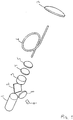
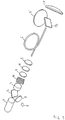
- Fig. 3 shows a perspective illustration of a multi-directional LIDAR system according to the present disclosure.
- the optical retarder 11 may be a rotatable wave plate, wherein the polarization of the output beam is rotated with respect to the angle of the waveplate, or a liquid crystal based optical retarder, where the polarization of the output beam is rotated when a voltage is applied across the retarder.
- the variable optical retarder can select whether the output beam is transmitted through the PBS 12 and through the lens 7 or reflected on the PBS and continuing through the lens 7'.
- the LIDAR system is directing the output beam in two directions by controlling the polarization of the light via the variable optical retarder 11.
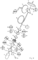
- This principle can be generalized as illustrated in fig. 4 .
- an additional PBS 13 and an additional variable optical retarder 11' in the optical path more directions of the output beam can be selected.
- the first variable optical retarder 11 toggles the polarization between two states such that the output beam propagates
- This second variable optical retarder 11' can again toggle the polarization between two states and in conjunction with the second PBS 12' select the second direction of the output beam through lens 7' and the third direction of the output beam through lens 7".
- a fourth direction of the output beam can be provided by placing a third variable optical retarder between PBS 13 and lens 5 to work in conjunction with PBS 12.
- An additional lens 7'" (not shown) would also be needed.
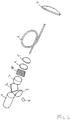
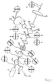
- Fig. 5 is a "functional" illustration of the setup in fig. 3 where the states of the polarization are indicated.
- the axes of polarization shown in fig. 5 are arbitrarily selected for illustrative purposes and illustrated via the inserted pictograms, as also illustrated to the right here.
- the output beam is illustrated with a fully drawn line whereas the reference beam and the received radiation are illustrated with dotted lines.
- the propagation directions of the beams are indicated with arrows.
- the reference beam is reflected from the reference beam generator 4.
- the output beam emitted from the light source 1 The output beam is emitted from the laser 1 as linearly polarized light, here illustrated as oscillating in the horizontal plane via the pictogram. After passage through the PBS 2 the polarization of the output beam is oscillating in the horizontal plane.
- the polarization of the output beam is rotated approx. 45 degrees to the right, as illustrated by the corresponding pictogram.
- the Faraday rotator could also have been adapted to rotate the polarization approx. 45 degrees to the left.
- the linear polarizer 10 and the mirror 4 do not change the polarization of the output beam.
- the variable optical retarder 11 switches the polarization of the output beam between the two orthogonal states “1” and “2” as illustrated by the pictograms.
- the PM fiber 6 transmits both states “1” and “2” without affecting the polarization.
- the "1” state is transmitted through the PBS 12 and through the lens 7 into a first direction of the output beam.
- the orthogonal "2" states is reflected off the PBS 12 and through the lens 7' into a second direction of the output beam.
- the radiation received from the measurement volume has the same polarization as the output beam as illustrated in the pictograms adjacent to the lenses 7, 7'.
- the received radiation propagates back through the optical fiber and through the variable optical retarder 11.
- the retarder is not a non-reciprocal optical element.
- the two orthogonal states "1" and "2" of the received radiation, oscillating in the horizontal and vertical plane, respectively, will be reversed back to the 45 degrees polarization state.
- the polarization of the received radiation will be rotated an additional 45 degrees thereby oscillating in the vertical plane, as illustrated in the corresponding pictogram.
- the received radiation will therefore be reflected off the initial PBS 2 and into the detector.
- the components are purely optical, whereas before the optical fiber there are electrically and/or mechanically driven components, such as the light source 1, the detector 9, the Faraday rotator 3 and the variable optical retarder 11.
- the electrically and/or mechanically driven components can be integrated inside the nacelle whereas the purely optical components such as PBS and lenses 7, 7' can be located outside the nacelle, e.g. on top of the wind turbine.
- the optical connection between the two sections of the LIDAR system is provided by a weather resistant optical cable comprising one or more PM optical fibers.
- Figs. 7 and 8 show examples that address this issue.
- the PBS 12 is placed after the telescope lens 12, whereas in fig. 8 the PBS is placed before the lens 5.
- the setup in fig. 8 naturally requires an additional lens 5' to pair with lens 7'.
- the PBS 12 is not located in the beam path between the telescopic configurations of lenses 5 and 7 (or 5' and 7').
- figs. 7 and 8 show examples of the LIDAR system according to the present invention without an optical fibre in the beam path.
- fig. 5 , 7 and 8 also show functional illustrations indicating polarization states along the optical axis.
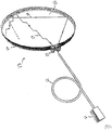
- Fig. 6 relates to optical heating of the exit window of a LIDAR system, i.e. essentially a defogging and/or deicing system.
- the heating light source 21 is coupled into a fiber optic cable 22 connected to a refractive element 24 that distributes the light from the fiber 22 into the window 23, which can be a normal window or a lens of the LIDAR system.
- the circular window 23 is provided with a rim 26 which is reflective on the inside.
- the light originating from the heating light source 21 then propagates inside the window 23 by means of e.g. total internal reflection between the two window surfaces, indicated as an example by the beam path 27, or the light may e.g. propagate directly through the window being reflected off the inside of the rim 28, as indicated by beam path 28.
- the heating and defogging/deicing of the window 23 can be provided in a place where electrical power is unavailable or unsuitable, e.g. on top of the nacelle of a wind turbine.
Description
- The present invention relates to a low-cost LIDAR system. The system may be integrated in a wind turbine for measurement of the approaching wind field.
- A coherent LIDAR system is an attractive system for determination of wind speed at remote locations. The basic principle relates to the Doppler shift that backscattered light from particles such as aerosols, water droplets, dust, etc. generates when irradiated by coherent laser light. Under the assumption that the particle movements resemble the air-flow closely, the measured Doppler frequency can be used for calculating of a hereto proportional wind speed.
- Prohibitive factors for wide spread use of LIDAR are cost, power consumption, size, and ruggedness. Today's commercially available LIDAR systems cost roughly 200 K USD, a price level that exclude many applications to be exploited. The use of LIDAR systems at remote places, such as off-shore wind turbine parks requires operation with little or no maintenance for long periods of time as well as lower power consumption.
- Previously the most expensive and complicated component in a coherent LIDAR system was the laser assembly. Due to an extremely low back scatter coefficient of the aerosols (∼10-12) a refined detection scheme is required that relies heavily on high quality, high power, coherent light sources. A low cost, compact and coherent LIDAR system with low power consumption was disclosed in
WO 2009/046717 employing an integrated semiconductor laser assembly. This LIDAR system is however limited to line of sight measurements prohibiting the determination of a wind field. - To be able to extent the wind speed measurement beyond the line of sight the probe beam of the LIDAR must be directed in multiple directions. This may be provided by a scanning LIDAR relying on a rotating mirror or prism assembly enabling measurement of the wind velocity in a three dimensional cone. However, having a rotating mirror on top of a wind turbine is not a rugged solution. One or more LIDARs may also be integrated in the rotating hub or on the blades of a wind turbine. Rotation of the hub and the blades ensure that the probe beam scans a cone in front of the wind turbine, but the rotating movements are not really compatible with the operating requirements of LIDAR.
WO 03/048804 US 2012/050750 discloses a LIDAR system.WO 2011/014743 discloses a beam steering device including stacked liquid crystal polarization gratings. - The market therefore still calls for a low-cost rugged LIDAR system that is not limited to line of sight measurements. This may be achieved by one embodiment of the present invention disclosing a LIDAR system comprising a beam generating section adapted for generating a substantially linearly polarized output beam, and a beam steering section comprising a first optical device for controllably altering the polarization of the output beam, said first optical device in optical connection with a first polarizing beam splitter, said beam steering section adapted for directing the output beam interchangeably between a first direction and a second direction.
- An inherited feature of a polarizing beam splitter is that it splits an incident beam into two beams of differing linear polarization, i.e. the beam propagation direction is depending on the polarization of the incident beam. The present invention exploits this feature of a polarizing beam splitter (PBS), i.e. by controlling the polarization of the incident beam the direction of propagation can be controlled. When incorporated into a LIDAR system the direction of the output beam is thereby variable if the polarization of the beam is controllable. As the polarization of light is controllable by mechanically passive components, i.e. without moving parts, the LIDAR system according to the present invention enables a rugged, low-cost LIDAR for determination of the speed and the direction of particles moving in a measurement volume thereby enabling the real-time determination of wind fields in front of e.g. a wind turbine.
WO 2012/019871 discloses a method for determining the velocity vector of particles in a measurement volume. - A further aspect of the present disclosure relates to a LIDAR system comprising a beam generating section adapted for generating a substantially linearly polarized output beam, and a polarization maintaining optical waveguide for propagating the output beam in a first direction and received radiation in a second and opposite direction, and a non-reciprocal optical element where through the output beam and the received radiation propagate in opposite directions, said non-reciprocal optical element adapted for rotating the polarization of the output beam and of the received radiation. An example of such a non-reciprocal optical element is a Faraday rotator that rotates the polarization of light due to the Faraday effect. Faraday rotation is an example of non-reciprocal optical propagation. Reflecting a linearly polarized beam back through the same Faraday medium does not undo the polarization change the beam underwent in its forward pass through the medium. The non-reciprocal optical element is preferably configured such that the polarization of the output beam and the polarization of the received radiation are substantially perpendicular to each other on one side of the optical element and substantially parallel to each other on the opposite side of the optical element. This may be exploited when received radiation and/or a reference beam needs to be split out for detection purposes.
- In a LIDAR system probe light is typically directed towards a measurement volume and received radiation propagates back though the system to be received by a detector. As a LIDAR system is typically operating outside, the components of the system are typically weather protected and the probe beam and the received signal is propagating through some sort of window. With changing weather conditions there is a risk of condensation on the window, which may drastically reduce the transparency of the window. This problem may quite easily be solved by having some sort of electrical heat source connected to the window to keep the window warm to avoid condensation. However, there may be situations where an electrically connected window is disadvantageous. For example when a LIDAR system is installed in a wind turbine. The probe beam must be emitted toward a measurement volume in front of the blades, i.e. preferential from the top, side or bottom of the nacelle. However, the electronically driven components of a LIDAR system would suffer if installed outside the nacelle, where lightning may frequently occur. Thus, preferably the electronically driven components of the LIDAR system, such as the beam generating section, is installed inside the nacelle whereas purely optical component which are not influenced by lightning, such as the beam steering section including the window, can be installed outside the nacelle. But with an electrically neutral beam steering section there is no power to heat the window, thus condensation may be an issue. Thus, a further aspect of the present disclosure relates to a LIDAR system comprising a beam generating section in optical connection with a beam steering section accommodating a window where through an output beam is transmitted, the beam generating section accommodating at least one heating light source with at least a part of the optical output of the heating light source transmitted to the beam steering section through at least one optical waveguide, wherein said at least one heating light source is adapted to heat said window. Thus, the basic idea is the heating light source is adapted to heat the window by converting electromagnetic energy of the optical output of the heating light source into thermal energy in the window.
- A further aspect of the present disclosure relates to a wind turbine comprising the presently disclosed LIDAR system. In particular a wind turbine comprising the presently disclosed LIDAR system, wherein the beam generating section is fully incorporated in the nacelle, the beam steering section is at least partly located outside the nacelle and the output beam and the received radiation is transmitted between the nacelle and the outside by means of a polarization maintaining optical fibre.
- A further aspect of the present disclosure relates to a sailboat comprising the presently disclosed LIDAR system. Yet a further aspect of the present disclosure relates to an airplane comprising the presently disclosed LIDAR system.
- The basic principles of the coherent LIDAR dates more than 35 years back, c.f. "Signal-to-Noise Relationships for Coaxial Systems that Heterodyne Backscatter from the Atmosphere", Applied Optics, Vol. 10, No.7, July 1971, C.M. Sonnenschein and F.A.Horrigan. The applications have traditionally been of scientific interest, for instance within atmosphere physics. However, nowadays the LIDAR has become more and more relevant for practical industrial applications. One such example is for the control of wind turbines. The need for higher efficiency has forced the wind turbine industry to continuously increase the wing span over the last decades in order to improve the performance in terms of extracted electrical energy per installed wind turbine. However an increased wing span leads to a substantial mechanical load imposed by strong winds and by wind turbulence in particular. A compact, rugged and cheap coherent LIDAR device for wind speed prediction tens of meters up-wind will allow for optimization and protection of the wind turbine. The time delay between the actual wind speed measurement and the time where the wind actual reached the wind turbine can be used to protect the load of the wings, for instance by changing the pitch of the wing. Another example is vortex detection generated by landing air crafts. The landing (or take off) frequency of aircrafts is primarily determined by a safety margin so as to ensure no hazard from vortexes generated by the previous aircraft. Using a coherent LIDAR for vortex surveillance allows this safety period to minimized, thus increasing the traffic intensity and thereby the capacity of the airport.
- A continuous wave (CW) coherent LIDAR rely on the focusing properties of the telescope used to confine the actual probe volume. The width of the probe volume is confined by the diameter of the laser beam in the focused region (i.e. the focal beam waist). The length of the probe volume along the beam axis is confined approximately by the depth of focus or twice the Rayleigh length of the focused laser beam. For a CW LIDAR focused at a distance of one hundred meters from the CW LIDAR system, the width of the probe volume is typically in the order of one centimetre and the length of the probe volume is in the order of ten meters depending on wavelength and focusing optics (the telescope). For pulsed systems the width of the probe volume is the same as for the CW LIDAR case, but the length of the probe volume is given by the smaller of cT/2 and the depth of focus where T is the emitted pulse width and c is the speed of light.
- The CW output power from the laser source used in a LIDAR system should be in the order of 1 Watt in order to obtain sufficient back scattered light to be detected. The homodyne detection technique requires firstly that the coherence length of the light source to be essentially two times the distance to probe volume, e.g. 200 meters for typical wind turbine applications. This corresponds to a full width half minimum (FWHM) of the laser spectrum of only a few 100 kHz relative to a centre frequency of about 200 THz. Secondly, the spatial coherence of the laser beam should be close to that of an ideal Gaussian beam, so as to ensure the generation of a maximum beat signal from the quadratic detector. The beat signal is characterized by the frequency difference between the reference signal and the back scattered - and Doppler shifted - signal. Finally, the relative intensity noise (RIN) of the laser should be sufficiently low to discriminate the beat signal at the detector.
WO 2009/046717 describes how to obtain these qualities by means of an integrated semiconductor laser assembly. - Although the term heterodyne detection is often used in connection with optical interferometry, the term homodyne detection is used throughout the present disclosure to signify that the reference beam (the local oscillator) is derived from the same source as the signal beam before the modulating process, i.e. the scattering by the target.
- The present diclosure will now be described in more detail with reference to the drawings in which
- Fig. 1
- is a perspective illustration of LIDAR system according to the invention,
- Fig. 2
- is the system from
fig. 1 with the addition of a linear polarizer, - Fig. 3
- is a perspective illustration of multidirectional LIDAR system according to the present disclosure where the output beam is directed in two different directions,
- Fig. 4
- is a perspective illustration of multidirectional LIDAR system according to the present disclosure where the output beam is directed in three different directions,
- Fig. 5
- is the system from
fig. 3 with indication of polarization states, and - Fig. 6
- is a perspective illustration of the coupling between a fibre coupled heating light source and a window/lens.
- Figs. 7 & 8
- are perspective illustrations of multidirectional LIDAR systems according to the present disclosure, without a PBS between the telescopic lenses.
- In one embodiment of the present disclosure the LIDAR system is a coherent Doppler LIDAR system.
- The basic configuration of the present LIDAR system is directing the output beam into two directions; the first and the second direction. However, the principle may be multiplied by adding more polarization controlling optical devices and more PBS's. Thus, in a further embodiment of the present disclosure the beam steering section further comprises a second optical device for controllably altering the polarization of the output beam propagating in the second direction, said second optical device in optical connection with a second polarizing beam splitter, said beam steering section adapted for directing the output beam interchangeably between the first direction, the second direction and a third direction. With three directions the output beam can be directed at a 3D measurement volume. However, more output beam directions, e.g. a fourth, fifth, sixth, seventh, eighth, ninth and tenth direction, may be added. Each additional pair of polarization controlling device and PBS can provide one or two new directions. This principle of adding more directions is illustrated in
fig. 4 . - In a LIDAR system the beam steering section is typically adapted for directing the output beam towards a measurement volume for illumination of particles in the measurement volume. The system may further comprise a lens arrangement for focusing the output beam onto a measurement volume.The target may be any object capable of interacting with light incident upon it resulting in scattering, absorption and/or emission of light from the target. The target in the measurement volume may for example be aerosols, such as water droplets, dust, etc., particles, molecules, atoms, a surface of an object larger than the width of the measurement volume, etc. throughout the present disclosure, the term "particles" includes aerosols, molecules, atoms, etc.
- A LIDAR system also typically comprises means for generating a reference beam. Preferably the reference beam is propagating at least coaxially with, and in the same direction as, the received signal beam and possibly also in the opposite direction of the output beam The reference beam may at least partly be generated by a partly reflecting mirror. The reference beam may alternatively at least partly be generated by the first or second end surface of an optical fiber.
- In the preferred embodiment of the present disclosure the LIDAR system is adapted for detecting, propagating and/or receiving radiation received from said first, second and/or third direction. The received radiation may e.g. comprise light emitted from particles in the measurement volume illuminated by the output beam. The received radiation is preferably propagating in the opposite direction of the output beam. The LIDAR system may further comprise a detector adapted for detection of a reference beam mixed with received radiation. In the preferred embodiment of the present disclosure the polarization of the reference beam is substantially equal to the polarization of the received radiation.
- In the preferred embodiment of the present disclosure the LIDAR system further comprises an initial polarizing beam splitter adapted for splitting out a reference beam and received radiation, both propagating in the opposite direction of the output beam.
- In one embodiment of the present disclosure the first and/or the second optical device may function as reciprocal polarization altering optical device. When a polarized beam is reflected back through the same reciprocal polarization altering optical device the polarization change the beam underwent in its forward pass through the device, may be undone depending on the polarization state of the beam and the configuration of the polarization altering optical device. A variable optical retarder can function as a reciprocal polarization altering optical device, at least in the case where the beam is linearly polarized. In one embodiment of the present disclosure the first and/or the second optical device is a variable optical retarder. A wave plate is an example of an optical retarder and a rotatable wave plate is an example of a variable optical retarder. When applying a linearly polarized beam to e.g. a half-waveplate, it emerges as a linearly polarized beam but its polarization (plane) is rotated with respect to the polarization (plane) of the incident beam. Thus, used in conjunction with a PBS the output beam may be directed in two different directions by rotating the wave plate correspondingly.
- Another example of a variable optical retarder is a liquid crystal variable optical retarder which consists of a transparent cell filled with a solution of liquid crystal molecules. Two parallel faces of the cell wall are coated with a transparent conductive film so that a voltage can be applied across the cell. The orientation of the liquid crystal molecules is determined by the alignment layer in the absence of an applied voltage. When an AC voltage is applied, the molecules will change from their default orientation based on the applied rms value of the voltage. Hence, the phase offset in a linearly polarized beam of light can be actively controlled by varying the applied voltage, i.e. by varying the applied voltage the polarization of an incident linearly polarized beam can be controllably rotated. A major advantage of this variable optical retarder is that there are no moving parts. Thus, in a further embodiment of the present disclosure the first and/or the second optical device is adapted for controllably altering the polarization of the output beam without moving parts. Preferably the first and/or the second optical device is adapted for controllably altering the polarization of the output beam between two specific states of polarization, preferably with a predefined frequency. A variable optical retarder may also be integrated in an optical fiber, where the phase offset in a linearly polarized beam propagating through this fiber can be controlled by e.g. piezoelectric elements in contact with the optical fiber. The advantage of such a solution is that a greater part of the optical path of the LIDAR system can be kept propagating inside an optical fiber.
- Said frequency may be approx. 1 Hz, such as between 0.01 Hz and 1 kHz, such as between 0.01 Hz and 0.1 Hz,such as between 0.1 Hz and 0.2 Hz, such as between 0.2 Hz and 0.3 Hz, such as between 0.3 Hz and 0.4 Hz, such as between 0.4 Hz and 0.5 Hz, such as between 0.5 Hz and 0.6 Hz, such as between 0.6 Hz and 0.7 Hz, such as between 0.7 Hz and 0.8 Hz, such as between 0.8 Hz and 0.9 Hz, such as between 0.9 Hz and 1 Hz, such as between 1 Hz and 1.5 Hz, such as between 1.5 Hz and 2 Hz, such as between 2 Hz and 3 Hz, such as between 3 Hz and 4 Hz, such as between 4 Hz and 5 Hz, such as between 5 Hz and 6 Hz, such as between 6 Hz and 7 Hz,such as between 7 Hz and 8 Hz,such as between 8 Hz and 9 Hz,such as between 9 Hz and 10 Hz, such as between 10 Hz and 15 Hz, such as between 15 Hz and 30 Hz,such as between 30 Hz and 60 Hz, such as between 60 Hz and 100 Hz, such as between 100 Hz and 1 kHz.
- In one embodiment of the present disclosure the optical connection between the first optical device and the first polarizing beam splitter is at least partly provided by a polarization maintaining optical waveguide. In a further embodiment the optical connection between the first optical device and the first polarizing beam splitter is at least partly provided by an optical fiber, preferably a polarization maintaining optical fiber, such as a Panda type PM fiber. Likewise for the connection between possible second, third, etc. optical devices and second, third, etc. PBS's. The LIDAR system may further comprise means for aligning the polarization of the output beam to the propagation direction of the polarization maintaining optical waveguide / fibre.
- In one embodiment of the present disclosure the beam generating section further comprises one or more polarizers, preferably absorptive polarizers, such as one or more linear polarizers, such as one or more 45 degree linear polarizers, located in the optical path. This may help to ensure that any unwanted polarization states in the optical path are absorbed.
- In one embodiment of the present disclosure the beam generating section further comprises a non-reciprocal optical element where through the output beam and the received radiation propagate in opposite directions, said non-reciprocal optical element adapted for rotating the polarization of the output beam and of the received radiation. An example of such a non-reciprocal optical element is a Faraday rotator that rotates the polarization of light due to the Faraday effect. Reflecting a polarized beam back through the same Faraday medium does not undo the polarization change the beam underwent in its forward pass through the medium. The non-reciprocal optical element is preferably configured such that the polarization of the output beam and the polarization of the received radiation are substantially perpendicular to each other on one side of the non-reciprocal optical element and substantially parallel to each other on the opposite side of the non-reciprocal optical element. A further advantage of the non-reciprocal optical element is that is allows sufficient suppression of stray light to enable the use of a low-cost semi-conductor laser with limited coherence time as the light source. The non-reciprocal optical element may further be adapted to rotate the polarization of the output beam by approx. 45 degrees when the output beam propagates through said non-reciprocal optical element. Likewise the non-reciprocal optical element may be adapted to rotate the polarization of the received radiation by approx. 45 degrees when the received radiation propagates through said non-reciprocal optical element. And further the non-reciprocal optical element may be adapted to rotate the polarization of the reference beam by approx. 45 degrees when the reference beam propagates through said non-reciprocal optical element. An advantage of having a non-reciprocal optical element, e.g. in the form of the Faraday rotator, is that a large part of the LIDAR may be allowed to propagate along a single optical axis.
- In one embodiment of the present disclosure the beam generating section comprises a coherent light source, such as a coherent laser, such as a semiconductor laser, such as an integrated semiconductor laser assembly, which may be a cost effective solution. Preferably the beam generating section comprises a coherent light source delivering a collimated linearly polarized output.
- Measurement of the Doppler shift of the back scattered signal from the measurement volume can be used for determination of the velocity of the particles. Thus, in a further embodiment of the present disclosure the LIDAR system may further comprise a signal processor. The signal processor may be adapted for generating a velocity signal corresponding to the velocity of the particles based on the detector signal. The signal processor may further be configured for determination of wind velocity, turbulence in the measurement volume, temperature in the measurement volume and/or particle concentration in the measurement volume. The amplitude of the backscattered Doppler shifted signal may be used for determination of the concentration of particles in the measurement volume. Thus, the signal processor may further be configured for generating a concentration signal corresponding to the concentration of the particles in the measurement volume based on the detector signal.
- In absence of a particle flow, i.e. the velocity is zero or very low, the Doppler frequency will be zero and the amplitude will be difficult to extract due to other DC signals coming from the detection process. One way to overcome this may be to include a frequency shifting element, e.g. an acousto-optic modulator, in the system for frequency shifting the output beam and/or the reference beam. Thereby a frequency bias may be added to the received signals corresponding to the frequency shift induced by the frequency shifting element.
- The detector signal output by a detector may e.g. contain the difference frequency of the reference beam and light emitted from the target corresponding to the Doppler shift generated by movement of the target in the measurement volume. In case of wind speed measurements, e.g. based on aerosols suspended in the air and following wind movements, turbulence information can be extracted.
- In case the medium residing in the measurement volume is a gas, Rayleigh scattering can be probed. Rayleigh scattering originates from the elastic interaction between the excitation light beam and the molecules of the gas. In that case the width of the Doppler spectrum corresponds to the temperature of the gas. Therefore, temperatures of gasses can be measured at long distances. It should be noted that compared to back scattered signals from aerosols, Rayleigh scattered signals are usually orders of magnitude smaller and depends strongly on the specific gas component and the excitation wavelength (Rayleigh scattering is a function of wavelength to the power of minus 4). Special gas components of interest could be oxygen, nitrogen, carbondioxide and NOx gasses.
- As stated above a further aspect of the present disclosure relates to a LIDAR system comprising a beam generating section in optical connection with a beam steering section accommodating a window where through an output beam is transmitted, the beam generating section accommodating at least one heating light source with at least a part of the optical output of the heating light source transmitted to the beam steering section through at least one optical waveguide, wherein said at least one heating light source is adapted to heat said window.
- Preferably said at least one heating light source is adapted to heat said window by converting electromagnetic energy of the optical output of the heating light source into thermal energy in the window. For example said at least one heating light source may be adapted to avoid condensation of at least a part of the window, i.e. a defogging system using only optical power as the source of heat. Preferably the optical waveguide comprises one or more optical fibres. The wavelength of the output beam is preferably different from the wavelength of the heating light source. The LIDAR system is typically provided with a detector that operates or is sensitive in a certain wavelength interval. Thus, preferably the wavelength of the heating light source is different from the detection wavelength interval of the LIDAR system. E.g. an InGaAs based detector is sensitive in a wavelength interval of approx. 800-1700 nm and the wavelength of the heating light source should then be selected outside of this range, e.g. above 1700 nm where eye-safety is not an issue. The wavelength of the heating light source may further be selected to be in the range of the absorption spectra of typical impurities in glass, such as OH absorption.
- The window may be a "normal" optical transparent window or it may be a lens in the LIDAR system, e.g. a lens adapted for focusing the output beam. The window is preferably elliptic, such as circular. The window is preferably provided with a first and a second surface. One or both surfaces of the window may be provided with antireflective coating.
- In the preferred embodiment of the present disclosure light from the heating light source is coupled in between the two surfaces of the window. The light from the heating light source can then propagate inside the window by means of total internal reflection between the two surfaces of the window. During this propagation the optical power is at least partly converted to heat in the window due to e.g. absorption due to impurities in the window. If the glass is of a high optical quality the presence of impurities may be low, but as the light propagates inside the window due to internal reflections from all surfaces the light does not easily exit ensuring that the beam path is relatively long, thereby ensuring a certain degree of absorption of the light. The window material may further be doped with one or more elements that absorb light from the heating light source, to increase the conversion of optical power to heat dissipated in the window.
- Light from the heating light source may be coupled in between the two surfaces of the window by means of refractive element, such as a coupling facet, prism or light-pipe. The refractive element is preferably concave, such that the light is distributed into the window over a wider exit angle. To prevent that light exits through the circumferential border of the window, this border may be provided with a metallic and/or reflective coating. The circumferential border may also be provided with some sort of rim where the inside of the rim is reflective, e.g. a metallic mounting rim, possibly a coated rim. Thus, light can be reflected back into the window and heat may be dissipated in the border/rim thereby helping to heat the window.
- The beam generating section may be physically separated from the beam steering section. Further, the beam generating section may be electrically separated from the beam steering section. And further the beam steering section may be electrically neutral. This aspect of the present disclosure may further comprise any of the herein stated LIDAR system features.
-
Fig. 1 schematically illustrates a uni-directional LIDAR system according to the present disclosure with a non-reciprocal element in the form of a Faraday rotator 3. Asemiconductor laser assembly 1 provides a linearly polarized output beam that is fully transmitted through the polarizing beam splitter (PBS) 2. The Faraday rotator 3 rotates the polarization of the output beam by approx. 45 degrees. The partly reflecting mirror 4 is coated to back-reflect a certain percentage of the output beam. The back reflected beam, i.e. the reference beam, is transmitted back through the Faraday rotator, i.e. in the opposite direction of the output. The polarization of the reference is now rotated an additional 45 degrees by the Faraday rotator due to the non-reciprocal propagation properties of the Faraday rotator. The result is that the polarization of the reference beam when incident on theinitial PBS 2 is perpendicular to the polarization of the output beam and the reference beam is therefore fully reflected by the surface of thePBS 2. The reference beam is focused by the lens 8 onto the detector 9. - The main percentage of the laser optical output, i.e. the output beam, is transmitted as linear polarized light through the reference window 4 and focused in to the polarization maintaining
optical fiber 6 by means of the focusinglens 5. The output beam is then focused onto the measurement volume (not shown) by means of the telescope lens 7. The focus distance of the telescope sets the measurement distance for the system. Particles or aerosols in the measurement volume have a velocity component directed along the propagation path of the transmitted output beam. A back-scattered and Doppler shifted signal beam from the measurement volume is received by the same lens 7 also used in the transmitter part and transmitted back through theoptical fiber 6, thelens 5 and the reference window 4. The polarization of the received radiation has been preserved all the way but when propagating through the Faraday rotator 3 the polarization of the received radiation is rotated an additional 45 degrees. The polarization of the received radiation is aligned with the polarization of the reference beam. The initial polarizing beam splitter 3 then fully reflects the received radiation to precisely align with and following the reference beam through the focusing lens 8 which focus both beams onto the detector 9. The surface of the detector may be slightly tilted to avoid any back reflections to propagate back in the optical path of the system. - The received radiation and the reference beam form a time evolving optical interference signal on the detector surface which, together with the detection process at the detector, forms a homodyne detection of the Doppler frequency of the received radiation. The detection means converts the optical signal into an electrical Doppler signal. The electrical Doppler signal from the detector 9 can be further amplified and Fourier analysed by a signal processor (not shown)
- Only a single semiconductor laser is necessary for generating the sufficient optical power needed to detect a Doppler signal. The combination of the
PBS 2 and the Faraday rotator 3 acts as beam director to direct all the optical power from the reference beam and the received radiation towards the detector 9. Also, the same combination of thepolarizing beam splitter 2 and the Faraday rotator 3 acts as an optical isolator which prevents any returning optical power to propagate towards thelaser 1. -
Fig. 2 corresponds to the setup infig. 1 with an additionallinear polarizer 10 to ensure that any unwanted polarization states in the optical path are absorbed. Please note that the linear polarizer will remove unwanted polarization states from the output beam propagating in one direction and from the received radiation and the reference beam propagating in the opposite direction. Infig. 2 the linear polarizer is located in the optical path between the Faraday rotator and the mirror 4, but it may be located anywhere in the optical path and several linear polarizers may be placed in the optical path. Infig. 2 the linear polarizer is illustrated with the wire-grid oriented at approx. 45 degrees to illustrate that the Faraday rotator has rotated the polarization of the output beam approx. 45 degrees. -
Fig. 3 shows a perspective illustration of a multi-directional LIDAR system according to the present disclosure. Compared to the system illustrated infig. 2 a variable optical retarder 11, aPBS 12 and an additional lens 7' have been inserted in the optical path. The optical retarder 11 may be a rotatable wave plate, wherein the polarization of the output beam is rotated with respect to the angle of the waveplate, or a liquid crystal based optical retarder, where the polarization of the output beam is rotated when a voltage is applied across the retarder. Used in conjunction with thePBS 12 the variable optical retarder can select whether the output beam is transmitted through thePBS 12 and through the lens 7 or reflected on the PBS and continuing through the lens 7'. Thus, the LIDAR system is directing the output beam in two directions by controlling the polarization of the light via the variable optical retarder 11. - This principle can be generalized as illustrated in
fig. 4 . By inserting an additional PBS 13 and an additional variable optical retarder 11' in the optical path more directions of the output beam can be selected. The first variable optical retarder 11 toggles the polarization between two states such that the output beam propagates - 1) through PBS 13, through
lens 5, into PMoptical fiber 6, reflected offPBS 12 and continuing through lens 7, which is a first direction of the output beam,
or the output beam is - 2) reflected off PBS 13 and through the second variable optical retarder 11'.
- This second variable optical retarder 11' can again toggle the polarization between two states and in conjunction with the second PBS 12' select the second direction of the output beam through lens 7' and the third direction of the output beam through lens 7". A fourth direction of the output beam can be provided by placing a third variable optical retarder between PBS 13 and
lens 5 to work in conjunction withPBS 12. An additional lens 7'" (not shown) would also be needed. -
Fig. 5 is a "functional" illustration of the setup infig. 3 where the states of the polarization are indicated. The axes of polarization shown infig. 5 are arbitrarily selected for illustrative purposes and illustrated via the insertedpictograms, as also illustrated to the right here. The output beam is illustrated with a fully drawn line whereas the reference beam and the received radiation are illustrated with dotted lines. The propagation directions of the beams are indicated with arrows. To distinguish the reference beam from the received radiation: The reference beam is reflected from the reference beam generator 4.
- First we follow the output beam emitted from the light source 1: The output beam is emitted from the
laser 1 as linearly polarized light, here illustrated as oscillating in the horizontal plane via the pictogram. After passage through thePBS 2 the polarization of the output beam is oscillating in the horizontal plane. When the output beam propagates through the Faraday rotator 3 the polarization of the output beam is rotated approx. 45 degrees to the right, as illustrated by the corresponding pictogram. The Faraday rotator could also have been adapted to rotate the polarization approx. 45 degrees to the left. Thelinear polarizer 10 and the mirror 4 do not change the polarization of the output beam. The variable optical retarder 11 switches the polarization of the output beam between the two orthogonal states "1" and "2" as illustrated by the pictograms. ThePM fiber 6 transmits both states "1" and "2" without affecting the polarization. The "1" state is transmitted through thePBS 12 and through the lens 7 into a first direction of the output beam. The orthogonal "2" states is reflected off thePBS 12 and through the lens 7' into a second direction of the output beam. - The radiation received from the measurement volume has the same polarization as the output beam as illustrated in the pictograms adjacent to the lenses 7, 7'. The received radiation propagates back through the optical fiber and through the variable optical retarder 11. The retarder is not a non-reciprocal optical element. In this case the two orthogonal states "1" and "2" of the received radiation, oscillating in the horizontal and vertical plane, respectively, will be reversed back to the 45 degrees polarization state. When the received radiation propagates through the non-reciprocal Faraday rotator the polarization of the received radiation will be rotated an additional 45 degrees thereby oscillating in the vertical plane, as illustrated in the corresponding pictogram. The received radiation will therefore be reflected off the
initial PBS 2 and into the detector. - Likewise with the reference beam which is generated by the mirror 4. This reflection maintains the 45 degrees polarization. When the reference beam propagates through the non-reciprocal Faraday rotator the polarization of the reference beam will be rotated an additional 45 degrees thereby oscillating in the vertical plane, as illustrated in the corresponding pictogram. The reference beam will therefore be reflected off the
initial PBS 2 and into the detector. - From
fig. 5 it is seen that on one side of the Faraday rotator the polarization of the output beam, the received radiation and the reference beam is aligned, whereas on the opposite side of the Faraday rotator the polarization of the output beam is perpendicular to the polarization of the received radiation and the reference beam. - From the drawings it can be seen that after the optical fiber the components are purely optical, whereas before the optical fiber there are electrically and/or mechanically driven components, such as the
light source 1, the detector 9, the Faraday rotator 3 and the variable optical retarder 11. Thus, when integrating the present LIDAR system in a wind turbine the electrically and/or mechanically driven components can be integrated inside the nacelle whereas the purely optical components such as PBS and lenses 7, 7' can be located outside the nacelle, e.g. on top of the wind turbine. The optical connection between the two sections of the LIDAR system is provided by a weather resistant optical cable comprising one or more PM optical fibers. Thus, the present disclosure provides a low-cost flexible LIDAR system. - In some instances it may be disadvantageous to the focusing capability of the LIDAR to place a PBS in highly converging or highly diverging beams.
Figs. 7 and8 show examples that address this issue. Infig. 7 thePBS 12 is placed after thetelescope lens 12, whereas infig. 8 the PBS is placed before thelens 5. The setup infig. 8 naturally requires an additional lens 5' to pair with lens 7'. Thus, infigs. 7 and8 thePBS 12 is not located in the beam path between the telescopic configurations oflenses 5 and 7 (or 5' and 7'). Please note thatfigs. 7 and8 show examples of the LIDAR system according to the present invention without an optical fibre in the beam path. Likewisefig. 5 ,7 and8 also show functional illustrations indicating polarization states along the optical axis. - As apparent from
figs. 5 ,7 and8 the employment of a non-reciprocal optical element in the form of the Faraday rotator allows a large part of the LIDAR to propagate along a single optical axis, i.e. a single optical axis between thepolarization beam splitters figs. 5 ,7 and8 . -
Fig. 6 relates to optical heating of the exit window of a LIDAR system, i.e. essentially a defogging and/or deicing system. Theheating light source 21 is coupled into afiber optic cable 22 connected to arefractive element 24 that distributes the light from thefiber 22 into thewindow 23, which can be a normal window or a lens of the LIDAR system. Thecircular window 23 is provided with arim 26 which is reflective on the inside. The light originating from theheating light source 21 then propagates inside thewindow 23 by means of e.g. total internal reflection between the two window surfaces, indicated as an example by thebeam path 27, or the light may e.g. propagate directly through the window being reflected off the inside of the rim 28, as indicated by beam path 28. When the light from theheating light source 21 propagates inside thewindow 23, light is gradually absorbed in thewindow 21. Some of the absorbed light is dissipated as heat in thewindow 23. By the total internal reflection and the reflection at the rim the light entering thewindow 23 will eventually have travelled a long effective path before being extinct due to absorption, thus ensuring an effective transformation of optical energy in the light into heat in the window. By using an optical fiber thelight source 21, that requires some sort of electrical power, can be physically separated from thewindow 23. Thus, the heating and defogging/deicing of thewindow 23 can be provided in a place where electrical power is unavailable or unsuitable, e.g. on top of the nacelle of a wind turbine.
Claims (15)
- A LIDAR system comprising- a beam generating section (1) for generating an output beam, and- means (4) for generating a reference beam,wherein the LIDAR system is configured for detecting, propagating and/or receiving radiation received from said first and second directions and wherein said received radiation is propagating in the opposite direction of the output beam,
characterized in that the LIDAR system comprises a beam steering section comprising a first optical device (11) for controllably altering the polarization of the output beam, said first optical device (11) in optical connection with a first polarizing beam splitter (12), said beam steering section adapted for directing the output beam interchangeably between a first and a second direction,
that the beam generating section (1) is adapted for generating a substantially linearly polarized output beam,
and that the beam generating section further comprises a non-reciprocal optical element (3) where through the output beam and the received radiation can propagate in opposite directions, said non-reciprocal optical element (3) adapted for rotating the polarization of the output beam and of the received radiation by approx. 45 degrees. - The LIDAR system according to claim 1, wherein said non-reciprocal optical element (3) is configured such that the polarization of the output beam and the polarization of the received radiation are substantially perpendicular to each other on one side of the non-reciprocal optical element (3) and substantially parallel to each other on the opposite side of the non-reciprocal optical element (3).
- The LIDAR system according to claim 2,
wherein the non-reciprocal optical element (3), such as a Faraday rotator (3), rotates the polarization of the light by means of the Faraday effect. - The LIDAR system according to any of preceding claims, wherein the beam steering section further comprises a second optical device (11') for controllably altering the polarization of the output beam propagating in the second direction, said second optical device (11') in optical connection with a second polarizing beam splitter (12'), said beam steering section adapted for directing the output beam interchangeably between the first direction, the second direction and a third direction, wherein the LIDAR system is configured for detecting, propagating and/or receiving radiation received from said first, second and/or third direction.
- The LIDAR system according to any of preceding claims, wherein the first optical device (11) and/or the second optical device (11') can function as a reciprocal optical element.
- The LIDAR system according to any of preceding claims, wherein the beam steering section is adapted for directing the output beam towards a measurement volume for illumination of particles in the measurement volume, and/or
further comprising a lens arrangement (5, 7) for focusing the output beam onto a measurement volume. - The LIDAR system according to any of preceding claims, further comprising a detector (9) adapted for detection of a reference beam mixed with received radiation.
- The LIDAR system according to any of preceding claims, further comprising an initial polarizing beam splitter (2) adapted for splitting out a reference beam and received radiation propagating in the opposite direction of the output beam.
- LIDAR system according to any of preceding claims, wherein the received radiation comprises light emitted or scattered from particles in a measurement volume illuminated by the output beam
- The LIDAR system according to any of preceding claims, wherein the first (11) and/or the second optical device (11') is a variable optical retarder, and/or wherein the first (11) and/or the second optical device (11') is a rotatable wave plate.
- The LIDAR system according to any of preceding claims, wherein the first (11) and/or the second optical device (11') is adapted for controllably altering the polarization of the output beam without moving parts.
- The LIDAR system according to any of preceding claims, wherein the first (11) and/or the second optical device (11') is adapted for controllably altering the polarization of the output beam between two specific states of polarization
- The LIDAR system according to any of preceding claims, wherein the first (11) and/or the second optical device (11') is adapted for controllably altering the polarization of the output beam between two specific states of polarization with a predefined frequency.
- The LIDAR system according to any of preceding claims, further comprising a signal processor configured for generating a velocity signal corresponding to the velocity of the particles based on the detector signal.
- The LIDAR system according to claim 14, wherein the signal processor is configured for determination of wind velocity.
Applications Claiming Priority (3)
| Application Number | Priority Date | Filing Date | Title |
|---|---|---|---|
| DKPA201270141 | 2012-03-23 | ||
| US201261638014P | 2012-04-25 | 2012-04-25 | |
| PCT/DK2013/050086 WO2013139347A1 (en) | 2012-03-23 | 2013-03-25 | Multiple directional lidar system |
Publications (2)
| Publication Number | Publication Date |
|---|---|
| EP2828687A1 EP2828687A1 (en) | 2015-01-28 |
| EP2828687B1 true EP2828687B1 (en) | 2020-08-05 |
Family
ID=49221858
Family Applications (1)
| Application Number | Title | Priority Date | Filing Date |
|---|---|---|---|
| EP13718292.9A Active EP2828687B1 (en) | 2012-03-23 | 2013-03-25 | Multiple directional lidar system |
Country Status (5)
| Country | Link |
|---|---|
| US (1) | US9784840B2 (en) |
| EP (1) | EP2828687B1 (en) |
| JP (1) | JP2015517094A (en) |
| CN (1) | CN104487865A (en) |
| WO (1) | WO2013139347A1 (en) |
Families Citing this family (37)
| Publication number | Priority date | Publication date | Assignee | Title |
|---|---|---|---|---|
| FI125286B (en) * | 2011-07-01 | 2015-08-14 | Teknologian Tutkimuskeskus Vtt Oy | Arrangement and method for detection of freezing |
| US8797966B2 (en) | 2011-09-23 | 2014-08-05 | Ofinno Technologies, Llc | Channel state information transmission |
| US8879496B2 (en) | 2011-12-19 | 2014-11-04 | Ofinno Technologies, Llc | Beamforming codeword exchange between base stations |
| JP2015517094A (en) | 2012-03-23 | 2015-06-18 | ウインダー フォトニクス エー/エスWindar Photonics A/S | Multi-directional LIDAR system |
| US9606234B2 (en) | 2013-10-18 | 2017-03-28 | Tramontane Technologies, Inc. | Amplified optical circuit |
| US10145944B1 (en) | 2014-05-02 | 2018-12-04 | Kla-Tencor Corporation | System and method for LADAR-based optic alignment and characterization |
| FR3021753B1 (en) | 2014-05-28 | 2017-12-01 | Thales Sa | LIDAR COMPRISING OPTICAL MEANS FOR DEFROSTING OR PREVENTING GIFRAGE |
| US9995277B2 (en) | 2014-07-31 | 2018-06-12 | General Electric Company | System and method for controlling the operation of wind turbines |
| EP3182152B1 (en) * | 2014-08-12 | 2019-05-15 | Mitsubishi Electric Corporation | Laser light sending and receiving device and laser radar device |
| JP6924149B2 (en) | 2015-01-13 | 2021-08-25 | ディーエスシージー ソルーションズ,インコーポレイテッド | Multi-beam distance measurement process |
| KR102454209B1 (en) * | 2015-07-30 | 2022-10-14 | 엘지이노텍 주식회사 | Apparatus for measuring Light Detection and Ranging |
| CN105374017B (en) * | 2015-11-30 | 2018-03-30 | 西安电子科技大学 | A kind of Polarimetric SAR Image filtering method of combination polarization decomposing vector statistical distribution |
| DE102016213344A1 (en) * | 2016-07-21 | 2018-01-25 | Robert Bosch Gmbh | Optical arrangement for a LiDAR system, LiDAR system and working device |
| KR101911601B1 (en) * | 2016-09-05 | 2018-10-24 | 한양대학교 산학협력단 | Optical rangefinder |
| CN106707292B (en) * | 2017-01-03 | 2019-04-26 | 濮阳光电产业技术研究院 | A kind of Doppler range rate measuring system based on optoelectronic oscillation |
| WO2018225496A1 (en) * | 2017-06-06 | 2018-12-13 | 株式会社日立製作所 | Distance measurement device and three-dimensional-shape measurement device |
| JP6513846B2 (en) | 2017-06-06 | 2019-05-15 | 株式会社日立製作所 | Distance measuring device and three-dimensional shape measuring device. |
| WO2019005258A2 (en) * | 2017-06-09 | 2019-01-03 | Hrl Laboratories, Llc | A cw lidar wind velocity sensor for operation on a stratospheric vehicle |
| CN107290733A (en) * | 2017-06-12 | 2017-10-24 | 北京理工大学 | The laser radar centered optical system of dual-mode antenna integration |
| DE102017210684A1 (en) * | 2017-06-26 | 2018-12-27 | Robert Bosch Gmbh | Detector arrangement for a lidar system |
| US11187806B2 (en) | 2017-07-24 | 2021-11-30 | Huawei Technologies Co., Ltd. | LIDAR scanning system |
| US10816649B1 (en) | 2017-09-14 | 2020-10-27 | The United States Of America As Represented By The Secretary Of The Air Force | Temporally multiplexed LADAR polarimeter |
| US10351103B2 (en) * | 2017-09-29 | 2019-07-16 | Aptiv Technologies Limited | LIDAR device with heated cover useful for automated vehicles |
| US11714168B2 (en) | 2017-11-01 | 2023-08-01 | Baraja Pty Ltd. | Optical circulator |
| KR102393439B1 (en) * | 2018-05-15 | 2022-05-03 | 현대모비스 주식회사 | Lidar apparatus for vehicle |
| JP6979391B2 (en) * | 2018-07-11 | 2021-12-15 | 株式会社日立製作所 | Distance measuring device, distance measuring method, and three-dimensional shape measuring device |
| US11698445B2 (en) * | 2018-09-04 | 2023-07-11 | GM Global Technology Operations LLC | Automotive Lidar with multi-spectral depth imaging and discrete scanning mechanism |
| JP2020153798A (en) * | 2019-03-19 | 2020-09-24 | 株式会社リコー | Optical device, distance measuring optical unit, distance measuring device, and distance measuring system |
| CN109946765B (en) * | 2019-04-02 | 2021-05-07 | 上海电气风电集团股份有限公司 | Prediction method and system for flow field of wind power plant |
| JP6956918B2 (en) * | 2019-04-05 | 2021-11-02 | 三菱電機株式会社 | Light distance measuring device |
| CN110531378B (en) * | 2019-06-13 | 2023-07-18 | 山西大学 | Continuous wave laser coherent wind-finding radar system of wind turbine generator |
| DE102019117968A1 (en) * | 2019-07-03 | 2021-01-07 | HELLA GmbH & Co. KGaA | Device for heating a cover of a vehicle |
| US11556000B1 (en) | 2019-08-22 | 2023-01-17 | Red Creamery Llc | Distally-actuated scanning mirror |
| CN110568453B (en) * | 2019-08-29 | 2021-10-01 | 北京空间机电研究所 | Wind measurement laser radar based on atmospheric molecular absorption and wind measurement method |
| CN111142121B (en) * | 2019-12-20 | 2022-04-08 | 自然资源部第二海洋研究所 | Brillouin scattering temperature measurement laser radar system based on two-stage virtual image phase array |
| US20220113390A1 (en) * | 2020-10-09 | 2022-04-14 | Silc Technologies, Inc. | Increasing signal-to-noise ratios in lidar systems |
| WO2023205881A1 (en) * | 2022-04-25 | 2023-11-02 | Leddartech Inc. | Apparatus for polarization control in lidar system |
Family Cites Families (22)
| Publication number | Priority date | Publication date | Assignee | Title |
|---|---|---|---|---|
| US5267010A (en) * | 1989-10-17 | 1993-11-30 | Kremer Richard M | Laser radar device |
| JP2550866B2 (en) * | 1993-06-28 | 1996-11-06 | 日本電気株式会社 | Lightwave ranging device |
| JPH09243746A (en) * | 1996-03-04 | 1997-09-19 | Nikon Corp | Distance sensor |
| JPH10103918A (en) * | 1996-09-27 | 1998-04-24 | Tokyo Seimitsu Co Ltd | Laser length-measuring apparatus |
| JPH10221014A (en) * | 1997-02-10 | 1998-08-21 | Sumitomo Metal Mining Co Ltd | Optical wave guide path displacement sensor |
| JPH11304923A (en) * | 1998-04-21 | 1999-11-05 | Ishikawajima Harima Heavy Ind Co Ltd | Laser visibility meter |
| JP3740525B2 (en) * | 2001-07-05 | 2006-02-01 | 独立行政法人 宇宙航空研究開発機構 | Wind disturbance prediction system |
| GB0128588D0 (en) | 2001-11-29 | 2002-01-23 | Qinetiq Ltd | Coherent laser radar apparatus |
| JP2004285858A (en) * | 2003-03-19 | 2004-10-14 | Mitsubishi Electric Corp | Wind power generation system and control method thereof |
| ITRM20040291A1 (en) * | 2004-06-16 | 2004-09-16 | Alenia Spazio Spa | BEAM SEPARATION APPARATUS FOR MONOSTATIC LIDARS. |
| US7457493B1 (en) * | 2005-05-14 | 2008-11-25 | Kent Optronics | Multi-beam multi-aperture optical beam steering module |
| IL180051A0 (en) * | 2006-12-13 | 2007-06-03 | Rafael Armament Dev Authority | Coherent optical range finder using transmitted pulse as local oscillator |
| EP2212717B1 (en) * | 2007-10-09 | 2015-03-18 | Windar Photonics A/S | Coherent lidar system based on a semiconductor laser and amplifier |
| CN101329426A (en) * | 2008-07-18 | 2008-12-24 | 清华大学 | Light beam multiplex switch and time-sharing synthetic method |
| US8797550B2 (en) | 2009-04-21 | 2014-08-05 | Michigan Aerospace Corporation | Atmospheric measurement system |
| CN201413396Y (en) * | 2009-06-03 | 2010-02-24 | 上海市浦东新区气象局 | Laser radar observation window anti-condensation device and laser radar observation device |
| WO2011014743A2 (en) * | 2009-07-31 | 2011-02-03 | North Carolina State University | Beam steering devices including stacked liquid crystal polarization gratings and related methods of operation |
| CN101630006B (en) * | 2009-08-19 | 2011-08-24 | 中国科学院上海光学精密机械研究所 | Lens focal plane array heterodyne reception optical antenna of synthetic aperture laser imaging radar |
| FR2953934B1 (en) | 2009-12-11 | 2011-12-09 | Thales Sa | OPTICAL ANEMOMETRIC PROBE WITH TWO AXIS OF MEASUREMENT |
| CN101924320A (en) * | 2010-07-07 | 2010-12-22 | 北京理工大学 | Fabry-Perot cavity based non-modulating 2 mu m laser frequency stabilizing method and device thereof |
| US9285385B2 (en) * | 2010-08-09 | 2016-03-15 | Technical University Of Denmark | Vector velocimeter |
| JP2015517094A (en) | 2012-03-23 | 2015-06-18 | ウインダー フォトニクス エー/エスWindar Photonics A/S | Multi-directional LIDAR system |
-
2013
- 2013-03-25 JP JP2015500772A patent/JP2015517094A/en active Pending
- 2013-03-25 CN CN201380022322.XA patent/CN104487865A/en active Pending
- 2013-03-25 US US14/386,961 patent/US9784840B2/en active Active
- 2013-03-25 EP EP13718292.9A patent/EP2828687B1/en active Active
- 2013-03-25 WO PCT/DK2013/050086 patent/WO2013139347A1/en active Application Filing
Non-Patent Citations (1)
| Title |
|---|
| None * |
Also Published As
| Publication number | Publication date |
|---|---|
| EP2828687A1 (en) | 2015-01-28 |
| US20150055115A1 (en) | 2015-02-26 |
| US9784840B2 (en) | 2017-10-10 |
| WO2013139347A1 (en) | 2013-09-26 |
| CN104487865A (en) | 2015-04-01 |
| JP2015517094A (en) | 2015-06-18 |
Similar Documents
| Publication | Publication Date | Title |
|---|---|---|
| EP2828687B1 (en) | Multiple directional lidar system | |
| RU2484500C2 (en) | Coherent lidar system based on semiconductor laser and amplifier | |
| JP2015517094A5 (en) | ||
| Bosch et al. | Optical feedback interferometry for sensing application | |
| US5164784A (en) | CW doppler lidar | |
| US20110292371A1 (en) | Method and Apparatus for a Pulsed Coherent Laser Range Finder | |
| US20150301178A1 (en) | Lidar measuring system and lidar measuring method | |
| US7221438B2 (en) | Coherent laser radar apparatus | |
| US20080094608A1 (en) | Laser velocimetry system | |
| RU2655040C1 (en) | Doppler scanning lidar of an onboard basing | |
| WO1999040398A1 (en) | Improvements in or relating to sound detection | |
| Wei et al. | Analysis of signal-to-noise ratio and heterodyne efficiency for reference-beam laser Doppler velocimeter | |
| Tanaka et al. | Wide range distance measurement over 50 km based on highly sensitive detection of the two-photon absorption photocurrent from a Si-APD | |
| Gordienko et al. | Wind Doppler lidar with 1.5 μm fiber laser | |
| US20220206150A1 (en) | Multi-axis velocity and rangefinder optical measurement device | |
| CA2724926A1 (en) | Servo-controlled bistatic anemometric probe | |
| CN114502986A (en) | Laser radar system for anemometry measurements | |
| Liu et al. | Influence of atmospheric aerosol single backscattering on waveform of target-reflected signal in incoherent frequency-modulation continuous-wave short-distance laser detection | |
| CN106646427B (en) | A kind of optical telescope of low shot noise | |
| Yang et al. | Research on a wind lidar without blind zone based on the technologies of pseudo random code phase modulation and heterodyne detection | |
| Zhang et al. | Vehicle-mounted validations of a 1.55-μ m all-fiber continuous-wave coherent laser radar for measuring aircraft airspeed | |
| Kashiwagi et al. | Long range and high resolution reflectometry by synthesis of optical coherence function at region beyond the coherence length | |
| Liu et al. | Design of A non-scanning lidar for wind velocity and direction measurement | |
| Jiang et al. | Analysis and test the performance of the coherent doppler lidar using a prism wedge in the scanning mode | |
| Rodrigo et al. | Development of semiconductor laser based Doppler lidars for wind-sensing applications |
Legal Events
| Date | Code | Title | Description |
|---|---|---|---|
| PUAI | Public reference made under article 153(3) epc to a published international application that has entered the european phase |
Free format text: ORIGINAL CODE: 0009012 |
|
| 17P | Request for examination filed |
Effective date: 20141020 |
|
| AK | Designated contracting states |
Kind code of ref document: A1 Designated state(s): AL AT BE BG CH CY CZ DE DK EE ES FI FR GB GR HR HU IE IS IT LI LT LU LV MC MK MT NL NO PL PT RO RS SE SI SK SM TR |
|
| AX | Request for extension of the european patent |
Extension state: BA ME |
|
| DAX | Request for extension of the european patent (deleted) | ||
| STAA | Information on the status of an ep patent application or granted ep patent |
Free format text: STATUS: EXAMINATION IS IN PROGRESS |
|
| 17Q | First examination report despatched |
Effective date: 20190625 |
|
| REG | Reference to a national code |
Ref country code: DE Ref legal event code: R079 Ref document number: 602013071286 Country of ref document: DE Free format text: PREVIOUS MAIN CLASS: G01S0017950000 Ipc: G01S0017580000 |
|
| GRAP | Despatch of communication of intention to grant a patent |
Free format text: ORIGINAL CODE: EPIDOSNIGR1 |
|
| STAA | Information on the status of an ep patent application or granted ep patent |
Free format text: STATUS: GRANT OF PATENT IS INTENDED |
|
| RIC1 | Information provided on ipc code assigned before grant |
Ipc: G01S 17/58 20060101AFI20200123BHEP Ipc: G01S 7/499 20060101ALI20200123BHEP Ipc: G01S 7/481 20060101ALI20200123BHEP Ipc: G01S 17/95 20060101ALI20200123BHEP Ipc: G02F 1/09 20060101ALI20200123BHEP |
|
| INTG | Intention to grant announced |
Effective date: 20200217 |
|
| GRAS | Grant fee paid |
Free format text: ORIGINAL CODE: EPIDOSNIGR3 |
|
| GRAA | (expected) grant |
Free format text: ORIGINAL CODE: 0009210 |
|
| STAA | Information on the status of an ep patent application or granted ep patent |
Free format text: STATUS: THE PATENT HAS BEEN GRANTED |
|
| AK | Designated contracting states |
Kind code of ref document: B1 Designated state(s): AL AT BE BG CH CY CZ DE DK EE ES FI FR GB GR HR HU IE IS IT LI LT LU LV MC MK MT NL NO PL PT RO RS SE SI SK SM TR |
|
| REG | Reference to a national code |
Ref country code: GB Ref legal event code: FG4D |
|
| REG | Reference to a national code |
Ref country code: CH Ref legal event code: EP |
|
| REG | Reference to a national code |
Ref country code: AT Ref legal event code: REF Ref document number: 1299495 Country of ref document: AT Kind code of ref document: T Effective date: 20200815 |
|
| REG | Reference to a national code |
Ref country code: DE Ref legal event code: R096 Ref document number: 602013071286 Country of ref document: DE |
|
| REG | Reference to a national code |
Ref country code: IE Ref legal event code: FG4D |
|
| REG | Reference to a national code |
Ref country code: LT Ref legal event code: MG4D |
|
| REG | Reference to a national code |
Ref country code: NL Ref legal event code: MP Effective date: 20200805 |
|
| REG | Reference to a national code |
Ref country code: AT Ref legal event code: MK05 Ref document number: 1299495 Country of ref document: AT Kind code of ref document: T Effective date: 20200805 |
|
| PG25 | Lapsed in a contracting state [announced via postgrant information from national office to epo] |
Ref country code: BG Free format text: LAPSE BECAUSE OF FAILURE TO SUBMIT A TRANSLATION OF THE DESCRIPTION OR TO PAY THE FEE WITHIN THE PRESCRIBED TIME-LIMIT Effective date: 20201105 Ref country code: NO Free format text: LAPSE BECAUSE OF FAILURE TO SUBMIT A TRANSLATION OF THE DESCRIPTION OR TO PAY THE FEE WITHIN THE PRESCRIBED TIME-LIMIT Effective date: 20201105 Ref country code: ES Free format text: LAPSE BECAUSE OF FAILURE TO SUBMIT A TRANSLATION OF THE DESCRIPTION OR TO PAY THE FEE WITHIN THE PRESCRIBED TIME-LIMIT Effective date: 20200805 Ref country code: GR Free format text: LAPSE BECAUSE OF FAILURE TO SUBMIT A TRANSLATION OF THE DESCRIPTION OR TO PAY THE FEE WITHIN THE PRESCRIBED TIME-LIMIT Effective date: 20201106 Ref country code: HR Free format text: LAPSE BECAUSE OF FAILURE TO SUBMIT A TRANSLATION OF THE DESCRIPTION OR TO PAY THE FEE WITHIN THE PRESCRIBED TIME-LIMIT Effective date: 20200805 Ref country code: AT Free format text: LAPSE BECAUSE OF FAILURE TO SUBMIT A TRANSLATION OF THE DESCRIPTION OR TO PAY THE FEE WITHIN THE PRESCRIBED TIME-LIMIT Effective date: 20200805 Ref country code: LT Free format text: LAPSE BECAUSE OF FAILURE TO SUBMIT A TRANSLATION OF THE DESCRIPTION OR TO PAY THE FEE WITHIN THE PRESCRIBED TIME-LIMIT Effective date: 20200805 Ref country code: SE Free format text: LAPSE BECAUSE OF FAILURE TO SUBMIT A TRANSLATION OF THE DESCRIPTION OR TO PAY THE FEE WITHIN THE PRESCRIBED TIME-LIMIT Effective date: 20200805 Ref country code: PT Free format text: LAPSE BECAUSE OF FAILURE TO SUBMIT A TRANSLATION OF THE DESCRIPTION OR TO PAY THE FEE WITHIN THE PRESCRIBED TIME-LIMIT Effective date: 20201207 Ref country code: FI Free format text: LAPSE BECAUSE OF FAILURE TO SUBMIT A TRANSLATION OF THE DESCRIPTION OR TO PAY THE FEE WITHIN THE PRESCRIBED TIME-LIMIT Effective date: 20200805 |
|
| PG25 | Lapsed in a contracting state [announced via postgrant information from national office to epo] |
Ref country code: IS Free format text: LAPSE BECAUSE OF FAILURE TO SUBMIT A TRANSLATION OF THE DESCRIPTION OR TO PAY THE FEE WITHIN THE PRESCRIBED TIME-LIMIT Effective date: 20201205 Ref country code: PL Free format text: LAPSE BECAUSE OF FAILURE TO SUBMIT A TRANSLATION OF THE DESCRIPTION OR TO PAY THE FEE WITHIN THE PRESCRIBED TIME-LIMIT Effective date: 20200805 Ref country code: RS Free format text: LAPSE BECAUSE OF FAILURE TO SUBMIT A TRANSLATION OF THE DESCRIPTION OR TO PAY THE FEE WITHIN THE PRESCRIBED TIME-LIMIT Effective date: 20200805 Ref country code: LV Free format text: LAPSE BECAUSE OF FAILURE TO SUBMIT A TRANSLATION OF THE DESCRIPTION OR TO PAY THE FEE WITHIN THE PRESCRIBED TIME-LIMIT Effective date: 20200805 Ref country code: NL Free format text: LAPSE BECAUSE OF FAILURE TO SUBMIT A TRANSLATION OF THE DESCRIPTION OR TO PAY THE FEE WITHIN THE PRESCRIBED TIME-LIMIT Effective date: 20200805 |
|
| PG25 | Lapsed in a contracting state [announced via postgrant information from national office to epo] |
Ref country code: SM Free format text: LAPSE BECAUSE OF FAILURE TO SUBMIT A TRANSLATION OF THE DESCRIPTION OR TO PAY THE FEE WITHIN THE PRESCRIBED TIME-LIMIT Effective date: 20200805 Ref country code: RO Free format text: LAPSE BECAUSE OF FAILURE TO SUBMIT A TRANSLATION OF THE DESCRIPTION OR TO PAY THE FEE WITHIN THE PRESCRIBED TIME-LIMIT Effective date: 20200805 Ref country code: CZ Free format text: LAPSE BECAUSE OF FAILURE TO SUBMIT A TRANSLATION OF THE DESCRIPTION OR TO PAY THE FEE WITHIN THE PRESCRIBED TIME-LIMIT Effective date: 20200805 Ref country code: EE Free format text: LAPSE BECAUSE OF FAILURE TO SUBMIT A TRANSLATION OF THE DESCRIPTION OR TO PAY THE FEE WITHIN THE PRESCRIBED TIME-LIMIT Effective date: 20200805 Ref country code: DK Free format text: LAPSE BECAUSE OF FAILURE TO SUBMIT A TRANSLATION OF THE DESCRIPTION OR TO PAY THE FEE WITHIN THE PRESCRIBED TIME-LIMIT Effective date: 20200805 |
|
| REG | Reference to a national code |
Ref country code: DE Ref legal event code: R097 Ref document number: 602013071286 Country of ref document: DE |
|
| PG25 | Lapsed in a contracting state [announced via postgrant information from national office to epo] |
Ref country code: AL Free format text: LAPSE BECAUSE OF FAILURE TO SUBMIT A TRANSLATION OF THE DESCRIPTION OR TO PAY THE FEE WITHIN THE PRESCRIBED TIME-LIMIT Effective date: 20200805 |
|
| PLBE | No opposition filed within time limit |
Free format text: ORIGINAL CODE: 0009261 |
|
| STAA | Information on the status of an ep patent application or granted ep patent |
Free format text: STATUS: NO OPPOSITION FILED WITHIN TIME LIMIT |
|
| PG25 | Lapsed in a contracting state [announced via postgrant information from national office to epo] |
Ref country code: SK Free format text: LAPSE BECAUSE OF FAILURE TO SUBMIT A TRANSLATION OF THE DESCRIPTION OR TO PAY THE FEE WITHIN THE PRESCRIBED TIME-LIMIT Effective date: 20200805 |
|
| 26N | No opposition filed |
Effective date: 20210507 |
|
| PG25 | Lapsed in a contracting state [announced via postgrant information from national office to epo] |
Ref country code: IT Free format text: LAPSE BECAUSE OF FAILURE TO SUBMIT A TRANSLATION OF THE DESCRIPTION OR TO PAY THE FEE WITHIN THE PRESCRIBED TIME-LIMIT Effective date: 20200805 |
|
| PG25 | Lapsed in a contracting state [announced via postgrant information from national office to epo] |
Ref country code: SI Free format text: LAPSE BECAUSE OF FAILURE TO SUBMIT A TRANSLATION OF THE DESCRIPTION OR TO PAY THE FEE WITHIN THE PRESCRIBED TIME-LIMIT Effective date: 20200805 |
|
| PG25 | Lapsed in a contracting state [announced via postgrant information from national office to epo] |
Ref country code: MC Free format text: LAPSE BECAUSE OF FAILURE TO SUBMIT A TRANSLATION OF THE DESCRIPTION OR TO PAY THE FEE WITHIN THE PRESCRIBED TIME-LIMIT Effective date: 20200805 |
|
| REG | Reference to a national code |
Ref country code: CH Ref legal event code: PL |
|
| REG | Reference to a national code |
Ref country code: BE Ref legal event code: MM Effective date: 20210331 |
|
| PG25 | Lapsed in a contracting state [announced via postgrant information from national office to epo] |
Ref country code: IE Free format text: LAPSE BECAUSE OF NON-PAYMENT OF DUE FEES Effective date: 20210325 Ref country code: CH Free format text: LAPSE BECAUSE OF NON-PAYMENT OF DUE FEES Effective date: 20210331 Ref country code: LU Free format text: LAPSE BECAUSE OF NON-PAYMENT OF DUE FEES Effective date: 20210325 Ref country code: LI Free format text: LAPSE BECAUSE OF NON-PAYMENT OF DUE FEES Effective date: 20210331 |
|
| PG25 | Lapsed in a contracting state [announced via postgrant information from national office to epo] |
Ref country code: BE Free format text: LAPSE BECAUSE OF NON-PAYMENT OF DUE FEES Effective date: 20210331 |
|
| PG25 | Lapsed in a contracting state [announced via postgrant information from national office to epo] |
Ref country code: HU Free format text: LAPSE BECAUSE OF FAILURE TO SUBMIT A TRANSLATION OF THE DESCRIPTION OR TO PAY THE FEE WITHIN THE PRESCRIBED TIME-LIMIT; INVALID AB INITIO Effective date: 20130325 |
|
| PG25 | Lapsed in a contracting state [announced via postgrant information from national office to epo] |
Ref country code: CY Free format text: LAPSE BECAUSE OF FAILURE TO SUBMIT A TRANSLATION OF THE DESCRIPTION OR TO PAY THE FEE WITHIN THE PRESCRIBED TIME-LIMIT Effective date: 20200805 |
|
| PGFP | Annual fee paid to national office [announced via postgrant information from national office to epo] |
Ref country code: GB Payment date: 20230919 Year of fee payment: 11 |
|
| PGFP | Annual fee paid to national office [announced via postgrant information from national office to epo] |
Ref country code: FR Payment date: 20230919 Year of fee payment: 11 Ref country code: DE Payment date: 20230920 Year of fee payment: 11 |