EP3296707A1 - Befestigungssystem und verfahren - Google Patents
Befestigungssystem und verfahren Download PDFInfo
- Publication number
- EP3296707A1 EP3296707A1 EP17189260.7A EP17189260A EP3296707A1 EP 3296707 A1 EP3296707 A1 EP 3296707A1 EP 17189260 A EP17189260 A EP 17189260A EP 3296707 A1 EP3296707 A1 EP 3296707A1
- Authority
- EP
- European Patent Office
- Prior art keywords
- sleeve
- sensor body
- recited
- flange
- sensor
- Prior art date
- Legal status (The legal status is an assumption and is not a legal conclusion. Google has not performed a legal analysis and makes no representation as to the accuracy of the status listed.)
- Granted
Links
Images

Classifications
-
- G—PHYSICS
- G01—MEASURING; TESTING
- G01K—MEASURING TEMPERATURE; MEASURING QUANTITY OF HEAT; THERMALLY-SENSITIVE ELEMENTS NOT OTHERWISE PROVIDED FOR
- G01K1/00—Details of thermometers not specially adapted for particular types of thermometer
- G01K1/08—Protective devices, e.g. casings
-
- G—PHYSICS
- G01—MEASURING; TESTING
- G01D—MEASURING NOT SPECIALLY ADAPTED FOR A SPECIFIC VARIABLE; ARRANGEMENTS FOR MEASURING TWO OR MORE VARIABLES NOT COVERED IN A SINGLE OTHER SUBCLASS; TARIFF METERING APPARATUS; MEASURING OR TESTING NOT OTHERWISE PROVIDED FOR
- G01D11/00—Component parts of measuring arrangements not specially adapted for a specific variable
-
- G—PHYSICS
- G01—MEASURING; TESTING
- G01D—MEASURING NOT SPECIALLY ADAPTED FOR A SPECIFIC VARIABLE; ARRANGEMENTS FOR MEASURING TWO OR MORE VARIABLES NOT COVERED IN A SINGLE OTHER SUBCLASS; TARIFF METERING APPARATUS; MEASURING OR TESTING NOT OTHERWISE PROVIDED FOR
- G01D11/00—Component parts of measuring arrangements not specially adapted for a specific variable
- G01D11/24—Housings ; Casings for instruments
-
- G—PHYSICS
- G01—MEASURING; TESTING
- G01D—MEASURING NOT SPECIALLY ADAPTED FOR A SPECIFIC VARIABLE; ARRANGEMENTS FOR MEASURING TWO OR MORE VARIABLES NOT COVERED IN A SINGLE OTHER SUBCLASS; TARIFF METERING APPARATUS; MEASURING OR TESTING NOT OTHERWISE PROVIDED FOR
- G01D11/00—Component parts of measuring arrangements not specially adapted for a specific variable
- G01D11/24—Housings ; Casings for instruments
- G01D11/245—Housings for sensors
-
- G—PHYSICS
- G01—MEASURING; TESTING
- G01D—MEASURING NOT SPECIALLY ADAPTED FOR A SPECIFIC VARIABLE; ARRANGEMENTS FOR MEASURING TWO OR MORE VARIABLES NOT COVERED IN A SINGLE OTHER SUBCLASS; TARIFF METERING APPARATUS; MEASURING OR TESTING NOT OTHERWISE PROVIDED FOR
- G01D11/00—Component parts of measuring arrangements not specially adapted for a specific variable
- G01D11/30—Supports specially adapted for an instrument; Supports specially adapted for a set of instruments
-
- G—PHYSICS
- G01—MEASURING; TESTING
- G01K—MEASURING TEMPERATURE; MEASURING QUANTITY OF HEAT; THERMALLY-SENSITIVE ELEMENTS NOT OTHERWISE PROVIDED FOR
- G01K1/00—Details of thermometers not specially adapted for particular types of thermometer
- G01K1/14—Supports; Fastening devices; Arrangements for mounting thermometers in particular locations
-
- G—PHYSICS
- G01—MEASURING; TESTING
- G01K—MEASURING TEMPERATURE; MEASURING QUANTITY OF HEAT; THERMALLY-SENSITIVE ELEMENTS NOT OTHERWISE PROVIDED FOR
- G01K7/00—Measuring temperature based on the use of electric or magnetic elements directly sensitive to heat ; Power supply therefor, e.g. using thermoelectric elements
- G01K7/02—Measuring temperature based on the use of electric or magnetic elements directly sensitive to heat ; Power supply therefor, e.g. using thermoelectric elements using thermoelectric elements, e.g. thermocouples
-
- G—PHYSICS
- G01—MEASURING; TESTING
- G01K—MEASURING TEMPERATURE; MEASURING QUANTITY OF HEAT; THERMALLY-SENSITIVE ELEMENTS NOT OTHERWISE PROVIDED FOR
- G01K7/00—Measuring temperature based on the use of electric or magnetic elements directly sensitive to heat ; Power supply therefor, e.g. using thermoelectric elements
- G01K7/16—Measuring temperature based on the use of electric or magnetic elements directly sensitive to heat ; Power supply therefor, e.g. using thermoelectric elements using resistive elements
-
- G—PHYSICS
- G01—MEASURING; TESTING
- G01L—MEASURING FORCE, STRESS, TORQUE, WORK, MECHANICAL POWER, MECHANICAL EFFICIENCY, OR FLUID PRESSURE
- G01L1/00—Measuring force or stress, in general
- G01L1/26—Auxiliary measures taken, or devices used, in connection with the measurement of force, e.g. for preventing influence of transverse components of force, for preventing overload
-
- G—PHYSICS
- G01—MEASURING; TESTING
- G01L—MEASURING FORCE, STRESS, TORQUE, WORK, MECHANICAL POWER, MECHANICAL EFFICIENCY, OR FLUID PRESSURE
- G01L19/00—Details of, or accessories for, apparatus for measuring steady or quasi-steady pressure of a fluent medium insofar as such details or accessories are not special to particular types of pressure gauges
- G01L19/14—Housings
-
- G—PHYSICS
- G01—MEASURING; TESTING
- G01L—MEASURING FORCE, STRESS, TORQUE, WORK, MECHANICAL POWER, MECHANICAL EFFICIENCY, OR FLUID PRESSURE
- G01L19/00—Details of, or accessories for, apparatus for measuring steady or quasi-steady pressure of a fluent medium insofar as such details or accessories are not special to particular types of pressure gauges
- G01L19/14—Housings
- G01L19/142—Multiple part housings
-
- G—PHYSICS
- G01—MEASURING; TESTING
- G01L—MEASURING FORCE, STRESS, TORQUE, WORK, MECHANICAL POWER, MECHANICAL EFFICIENCY, OR FLUID PRESSURE
- G01L19/00—Details of, or accessories for, apparatus for measuring steady or quasi-steady pressure of a fluent medium insofar as such details or accessories are not special to particular types of pressure gauges
- G01L19/14—Housings
- G01L19/142—Multiple part housings
- G01L19/143—Two part housings
-
- G—PHYSICS
- G01—MEASURING; TESTING
- G01L—MEASURING FORCE, STRESS, TORQUE, WORK, MECHANICAL POWER, MECHANICAL EFFICIENCY, OR FLUID PRESSURE
- G01L19/00—Details of, or accessories for, apparatus for measuring steady or quasi-steady pressure of a fluent medium insofar as such details or accessories are not special to particular types of pressure gauges
- G01L19/14—Housings
- G01L19/147—Details about the mounting of the sensor to support or covering means
-
- G—PHYSICS
- G01—MEASURING; TESTING
- G01N—INVESTIGATING OR ANALYSING MATERIALS BY DETERMINING THEIR CHEMICAL OR PHYSICAL PROPERTIES
- G01N27/00—Investigating or analysing materials by the use of electric, electrochemical, or magnetic means
- G01N27/26—Investigating or analysing materials by the use of electric, electrochemical, or magnetic means by investigating electrochemical variables; by using electrolysis or electrophoresis
- G01N27/403—Cells and electrode assemblies
- G01N27/406—Cells and probes with solid electrolytes
- G01N27/407—Cells and probes with solid electrolytes for investigating or analysing gases
- G01N27/4078—Means for sealing the sensor element in a housing
-
- G—PHYSICS
- G01—MEASURING; TESTING
- G01N—INVESTIGATING OR ANALYSING MATERIALS BY DETERMINING THEIR CHEMICAL OR PHYSICAL PROPERTIES
- G01N29/00—Investigating or analysing materials by the use of ultrasonic, sonic or infrasonic waves; Visualisation of the interior of objects by transmitting ultrasonic or sonic waves through the object
- G01N29/22—Details, e.g. general constructional or apparatus details
- G01N29/225—Supports, positioning or alignment in moving situation
-
- G—PHYSICS
- G01—MEASURING; TESTING
- G01N—INVESTIGATING OR ANALYSING MATERIALS BY DETERMINING THEIR CHEMICAL OR PHYSICAL PROPERTIES
- G01N1/00—Sampling; Preparing specimens for investigation
- G01N1/02—Devices for withdrawing samples
- G01N1/22—Devices for withdrawing samples in the gaseous state
- G01N2001/2285—Details of probe structures
Definitions
- the present invention relates to retaining systems, and more particularly to retaining systems for Resistance Temperature Detectors (RTDs), for example RTDs placed in bores.
- RTDs Resistance Temperature Detectors
- RTDs and other sensors are commonly placed in bores under high temperature conditions and used to measure temperature.
- the RTD can be retained in a given bore against vibratory loads to ensure that the sensing portion is aligned correctly with the target bore.
- this is accomplished with an uncontained cylindrical rubber sponge and seal rings, e.g. o-rings. This tends to lead to undue stress placed on the wire bundle under certain conditions, which in turn can lead to increased maintenance.
- Many common sensors and systems, such as RTDs are sensitive to errors introduced due to the effects on the wire bundle, such as short circuits.
- a sensor system includes a sensor body with a proximal end and a distal end.
- the sensor body includes a radially extending flange positioned between the proximal end and the distal end.
- the radially extending flange of the sensor body includes a flange surface.
- a sleeve is positioned radially outward from the sensor body surrounding the proximal end of the sensor body.
- the sleeve has a radially extending end flange with an end surface configured to contact the flange surface of the radially extending flange of the sensor body to transfer a load between the sleeve and the sensor body.
- the system includes a biasing component radially outward from the sleeve.
- the biasing component can be a pad that includes a shock absorbing material, and/or a helical spring.
- the biasing component can be configured to contact an axially facing outer surface of the radially extending end flange of the sleeve to apply an axial load to the sleeve.
- the sleeve can be configured to extend longitudinally beyond the biasing component in both directions when installed in the sensor system.
- the system can include an annular member radially outward from the sleeve.
- the biasing component can include first and second axially facing surfaces. The first axially facing surface can abut a surface of the annular member. The second axially facing surface can abut an outer axially facing surface of the radially extending end flange of the sleeve to apply an axial load to the sleeve.
- the radially extending end flange of the sleeve can extend axially beyond a second end of the biasing component.
- the system can include a retaining member abutting at least a portion of an axial surface of the annular member to keep the annular member in place in the axial direction.
- the system can include a wire casing operatively connected to and extending axially from the proximal end of the sensor body to surround wires extending from the proximal end of the sensor body. Wires can extend from the proximal end of the sensor body.
- the wire casing can be radially outward from the wires.
- the wire casing can surround the wires.
- a sensor retaining system includes a sleeve sized and configured to abut a radially extending flange of a sensor body.
- a biasing component is radially outward from the sleeve and configured to apply an axial load to the sleeve.
- the biasing component is a pad that includes a shock absorbing material, and/or a helical spring.
- the sleeve can be configured to extend longitudinally beyond the biasing component in both directions when installed in the sensor system.
- a wire casing can be nested within the sleeve, wherein at least a portion of the wire casing extends axially from the first end of the sleeve.
- An annular member can be positioned radially outward from the sleeve, similar to the annular member described above.
- a retaining member can abut at least a portion of an axial surface of the annular member, similar to the retaining member described above.
- a first axially facing surface of the biasing component can abut a surface of the annular member.
- a second axially facing surface of the biasing component can abut an outer axially facing surface of the radially extending end flange of the sleeve.
- a method of disassembling a sensor system includes axially moving a rigid sleeve where the rigid sleeve axially abuts a portion of a sensor body positioned within a bore of a housing.
- the method includes axially removing a biasing member from the bore with the moving of the rigid sleeve.
- Fig. 1 a partial view of an exemplary embodiment of a sensor system is shown in Fig. 1 and is designated generally by reference character 100.
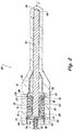
- Other embodiments of sensor systems and methods, or aspects thereof are also shown and described with reference to Fig. 2 .
- the systems and methods described herein can be used, for example, to retain a sensor body and reduce stress imposed on a wire bundle extending from the sensor.
- a sensor system 100 includes a sensor body 102 with a proximal end 104 and a second end 106.
- Sensor body 102 defines a longitudinal axis A between proximal and distal ends.
- Sensor body 102 includes a radially extending flange 108 between proximal and distal ends 104 and 106, respectively.
- Sensor body 102 can be an RTD sensor, thermocouple, or the like.
- Sensor body 102 is disposed in a bore 110 formed in a structure 112, such as a turbomachine.
- Sensor system 100 includes a sensor retaining system 101.
- Sensor retaining system 101 includes a sleeve 114 radially outward from sensor body 102 surrounding proximal end of sensor body 102.
- Sleeve 114 can be a rigid sleeve, e.g. a metal sleeve.
- System 101 includes a biasing component, e.g. a pad 122, radially outward from sleeve 114.
- Pad 122 is a shock absorbing material and/or compressible resilient material, such as a rubber sponge or the like.
- Sleeve 114 includes a radially extending end flange 116 with an end surface 118 that abuts a flange surface 120 of radially extending flange 108 of sensor body 102 to transfer a pre-load to sensor body 102.
- an outer surface 115 of sleeve 114 and an inner surface 150 of bore 110 compress pad 122 radially and restrict pad 122 from expanding in the radial direction. This reduces the possibility of pad 122 impinging upon wires, wire casing or sensor body 102 and causing short-circuits.
- a second axially facing surface 136 of pad 122 abuts an axially facing outer surface 124 of radially extending end flange 116 of sleeve 114 to apply an axial pre-load to sleeve 114.
- sensor retaining system 101 acts to axially pre-load sensor body 102 against a stop surface 148 in bore 110.
- sleeve 114 includes an end 126, opposite from radially extending end flange 116, which extends axially beyond a first end 128 of pad 122.
- This extension provides a gripping area during removal of sensor body 102 from bore 110 so that the user does not have to grip onto wires 146 or wire casing 144 to get access to sensor body 102, thereby reducing potential stress on wire bundle, e.g. wires 146 and/or wire casing 144.
- Radially extending end flange 116 of sleeve 114 extends axially beyond a second end 130 of pad 122.
- System 101 includes an annular member 132, e.g.
- Pad 122 includes first and second axially facing surfaces 134 and 136, respectively. First axially facing surface 134 abuts a surface 138 of annular member 132. Pad 122 is compressed between outer axially facing surface 124 of radially extending end flange 116 of sleeve 114 and surface 138 of annular member 132.
- system 101 includes a retaining member 140, e.g. a snap ring, abutting at least a portion of an axial facing surface 142 of annular member 132 to keep annular member 132 in place with respect to the axial direction, e.g. along a line parallel to longitudinal axis A.
- End 126 of sleeve 114 extends axially beyond proximal end 104 of sensor body 102 so that sleeve 114 can be gripped to remove pad 122, after retaining member 140 and annular member 132 have been removed, without pulling on wires 146.
- System 101 includes a wire casing 144 operatively connected to and extending axially from proximal end 104 of sensor body 102 to surround wires 146 extending from proximal end 104 of sensor body 102.
- Wire casing 144 can be a shrink sleeve, or the like.
- Wire casing 144 is nested within sleeve 114, between sleeve 114 and proximal end 104 of sensor body 102. At least a portion of wire casing 144 extends axially from first end 126 of sleeve 114.
- Wires 146 extend from proximal end 104 of sensor body 102.
- Wire casing 144 is radially outward from and surrounds wires 146.
- a sensor system 200 is similar to system 100 described above.
- System 200 includes a sensor body 102 similar to the sensor body described above.
- Sensor body 102 is disposed in a bore 110 formed in a structure 112, such as a turbomachine.
- Sensor system 200 includes a sensor retaining system 201.
- Sensor retaining system 201 is similar to sensor retaining system 101 described above, except instead of the biasing component being a pad 122, it is a helical spring 222.
- Helical spring 222 includes a first axially facing surface 234 and a second axially facing surface 236, similar to first and second axially facing surfaces 134 and 136, respectively.
- Helical spring 222 includes a first end 228 and a second end 230, similar to first and second ends 128 and 130, respectively. Helical spring 222 operates similarly to pad 122, in that helical spring 222 transfers a pre-load to sensor body 102 through sleeve 114.
- a method of disassembling a sensor system includes axially moving a sleeve, e.g. sleeve 114, where the sleeve axially abuts a portion of a sensor body, e.g. sensor body 102, positioned within a bore, e.g. bore 110, of a housing, e.g. structure 112.
- the method includes axially removing a biasing member, e.g. biasing members 122 or 222, from the bore with the moving of the sleeve.
Landscapes
- Physics & Mathematics (AREA)
- General Physics & Mathematics (AREA)
- Chemical & Material Sciences (AREA)
- Analytical Chemistry (AREA)
- Health & Medical Sciences (AREA)
- Life Sciences & Earth Sciences (AREA)
- Biochemistry (AREA)
- General Health & Medical Sciences (AREA)
- Immunology (AREA)
- Pathology (AREA)
- Molecular Biology (AREA)
- Chemical Kinetics & Catalysis (AREA)
- Electrochemistry (AREA)
- Measuring Temperature Or Quantity Of Heat (AREA)
- Force Measurement Appropriate To Specific Purposes (AREA)
Applications Claiming Priority (1)
| Application Number | Priority Date | Filing Date | Title |
|---|---|---|---|
| US15/257,128 US10677658B2 (en) | 2016-09-06 | 2016-09-06 | Retaining systems and methods |
Publications (2)
| Publication Number | Publication Date |
|---|---|
| EP3296707A1 true EP3296707A1 (de) | 2018-03-21 |
| EP3296707B1 EP3296707B1 (de) | 2019-07-10 |
Family
ID=59955338
Family Applications (1)
| Application Number | Title | Priority Date | Filing Date |
|---|---|---|---|
| EP17189260.7A Active EP3296707B1 (de) | 2016-09-06 | 2017-09-04 | Befestigungssystem und verfahren |
Country Status (2)
| Country | Link |
|---|---|
| US (1) | US10677658B2 (de) |
| EP (1) | EP3296707B1 (de) |
Cited By (1)
| Publication number | Priority date | Publication date | Assignee | Title |
|---|---|---|---|---|
| WO2021048566A1 (en) * | 2019-09-13 | 2021-03-18 | Mixergy Limited | Temperature sensor |
Citations (2)
| Publication number | Priority date | Publication date | Assignee | Title |
|---|---|---|---|---|
| WO2011094753A2 (en) * | 2010-02-01 | 2011-08-04 | Stoneridge, Inc. | Exhaust gas temperature sensor including strain relief and/or anti-vibration sleeve |
| US20150219502A1 (en) * | 2012-09-17 | 2015-08-06 | Tesona Gmbh & Co.Kg | High temperature sensor with a protective tube in the cold section |
Family Cites Families (8)
| Publication number | Priority date | Publication date | Assignee | Title |
|---|---|---|---|---|
| US3832669A (en) * | 1970-08-10 | 1974-08-27 | Royal Medical Corp | Temperature-sensing device |
| US3745828A (en) * | 1972-02-09 | 1973-07-17 | United States Steel Corp | Temperature sensing device for continuouscasting molds |
| JPS5289989A (en) * | 1976-01-23 | 1977-07-28 | Hitachi Ltd | Oxygen concentration detector |
| US4101343A (en) * | 1976-09-02 | 1978-07-18 | Aluminum Company Of America | Thermocouple device |
| FR2492096A1 (fr) * | 1980-10-14 | 1982-04-16 | Saint Gobain Emballage | Canne pyrometrique |
| US4786397A (en) * | 1987-10-09 | 1988-11-22 | Allied-Signal Inc. | Seal for single wire O2 sensor |
| JP4981413B2 (ja) * | 2006-11-02 | 2012-07-18 | 三菱重工業株式会社 | 軸受温度監視装置及びこれをそなえた軸受装置 |
| US9057654B2 (en) * | 2012-05-01 | 2015-06-16 | James H. Gammon | Differential pressure gauge |
-
2016
- 2016-09-06 US US15/257,128 patent/US10677658B2/en active Active
-
2017
- 2017-09-04 EP EP17189260.7A patent/EP3296707B1/de active Active
Patent Citations (2)
| Publication number | Priority date | Publication date | Assignee | Title |
|---|---|---|---|---|
| WO2011094753A2 (en) * | 2010-02-01 | 2011-08-04 | Stoneridge, Inc. | Exhaust gas temperature sensor including strain relief and/or anti-vibration sleeve |
| US20150219502A1 (en) * | 2012-09-17 | 2015-08-06 | Tesona Gmbh & Co.Kg | High temperature sensor with a protective tube in the cold section |
Cited By (2)
| Publication number | Priority date | Publication date | Assignee | Title |
|---|---|---|---|---|
| WO2021048566A1 (en) * | 2019-09-13 | 2021-03-18 | Mixergy Limited | Temperature sensor |
| GB2587598B (en) * | 2019-09-13 | 2022-06-08 | Mixergy Ltd | Temperature sensor |
Also Published As
| Publication number | Publication date |
|---|---|
| US20180066997A1 (en) | 2018-03-08 |
| EP3296707B1 (de) | 2019-07-10 |
| US10677658B2 (en) | 2020-06-09 |
Similar Documents
| Publication | Publication Date | Title |
|---|---|---|
| US8910722B2 (en) | Slip-deployed anti-extrusion backup ring | |
| US2585453A (en) | Interchangeable, self-releasing, self-locking high-pressure tube and pipe connector unit | |
| CN108425941B (zh) | 滚子轴承用的状态检测装置及滚子轴承装置 | |
| EP3196612A1 (de) | Sensorvorrichtung | |
| US3040405A (en) | Compression type stop collar | |
| EP3296707B1 (de) | Befestigungssystem und verfahren | |
| AU2015248125B2 (en) | Slip release assembly with cone undermining feature | |
| EP1425533B1 (de) | Stützhülse zur verwendung in einer rohrkupplung und kupplungsgehäuse zur verwendung zusammen mit der hülse | |
| DK2994599T3 (en) | Cable Protection Device | |
| EP2436936A1 (de) | System zur Prüfung der Schraubenvorspannung | |
| CN108136601B (zh) | 用于机器人校准的剪断销 | |
| US3214204A (en) | Retainer assembly | |
| KR101746405B1 (ko) | 온도센서의 단부지지부재의 부착구조 | |
| CN107980018B (zh) | 用于动力扳钳的螺母套筒单元 | |
| EP3284979A2 (de) | Gebundene dichtung mit integralem sicherungsring | |
| EP1398607A2 (de) | Kupplung für Drehmomentsensor | |
| JP2019537696A5 (de) | ||
| CA2678743A1 (en) | Protection elements for pipeline investigation devices | |
| CN104466522B (zh) | 适合于被连接到燃气安全阀和热电偶的热电偶连接器 | |
| US20060105846A1 (en) | Boot for a joint | |
| EP3426961B1 (de) | Hochdruckschlauchkupplung | |
| EP2924305A1 (de) | Wellenklemmenanordnung und Verfahren zu ihrer Verwendung | |
| US3574385A (en) | Grappling device | |
| KR20140034831A (ko) | 필드 확대를 위한 장치 및 방법 | |
| JP6555070B2 (ja) | 歪み式腐食センサの製造方法および腐食測定方法 |
Legal Events
| Date | Code | Title | Description |
|---|---|---|---|
| PUAI | Public reference made under article 153(3) epc to a published international application that has entered the european phase |
Free format text: ORIGINAL CODE: 0009012 |
|
| STAA | Information on the status of an ep patent application or granted ep patent |
Free format text: STATUS: THE APPLICATION HAS BEEN PUBLISHED |
|
| AK | Designated contracting states |
Kind code of ref document: A1 Designated state(s): AL AT BE BG CH CY CZ DE DK EE ES FI FR GB GR HR HU IE IS IT LI LT LU LV MC MK MT NL NO PL PT RO RS SE SI SK SM TR |
|
| AX | Request for extension of the european patent |
Extension state: BA ME |
|
| STAA | Information on the status of an ep patent application or granted ep patent |
Free format text: STATUS: REQUEST FOR EXAMINATION WAS MADE |
|
| STAA | Information on the status of an ep patent application or granted ep patent |
Free format text: STATUS: EXAMINATION IS IN PROGRESS |
|
| 17P | Request for examination filed |
Effective date: 20180920 |
|
| RBV | Designated contracting states (corrected) |
Designated state(s): AL AT BE BG CH CY CZ DE DK EE ES FI FR GB GR HR HU IE IS IT LI LT LU LV MC MK MT NL NO PL PT RO RS SE SI SK SM TR |
|
| 17Q | First examination report despatched |
Effective date: 20181015 |
|
| GRAP | Despatch of communication of intention to grant a patent |
Free format text: ORIGINAL CODE: EPIDOSNIGR1 |
|
| STAA | Information on the status of an ep patent application or granted ep patent |
Free format text: STATUS: GRANT OF PATENT IS INTENDED |
|
| INTG | Intention to grant announced |
Effective date: 20190124 |
|
| RIN1 | Information on inventor provided before grant (corrected) |
Inventor name: CORETTO, AUGUST M. Inventor name: RICKIS, AARON Inventor name: VEGA, JORGE L. |
|
| GRAA | (expected) grant |
Free format text: ORIGINAL CODE: 0009210 |
|
| STAA | Information on the status of an ep patent application or granted ep patent |
Free format text: STATUS: THE PATENT HAS BEEN GRANTED |
|
| AK | Designated contracting states |
Kind code of ref document: B1 Designated state(s): AL AT BE BG CH CY CZ DE DK EE ES FI FR GB GR HR HU IE IS IT LI LT LU LV MC MK MT NL NO PL PT RO RS SE SI SK SM TR |
|
| REG | Reference to a national code |
Ref country code: GB Ref legal event code: FG4D |
|
| REG | Reference to a national code |
Ref country code: CH Ref legal event code: EP Ref country code: AT Ref legal event code: REF Ref document number: 1154084 Country of ref document: AT Kind code of ref document: T Effective date: 20190715 |
|
| REG | Reference to a national code |
Ref country code: DE Ref legal event code: R096 Ref document number: 602017005161 Country of ref document: DE |
|
| REG | Reference to a national code |
Ref country code: IE Ref legal event code: FG4D |
|
| REG | Reference to a national code |
Ref country code: NL Ref legal event code: MP Effective date: 20190710 |
|
| REG | Reference to a national code |
Ref country code: LT Ref legal event code: MG4D |
|
| REG | Reference to a national code |
Ref country code: AT Ref legal event code: MK05 Ref document number: 1154084 Country of ref document: AT Kind code of ref document: T Effective date: 20190710 |
|
| PG25 | Lapsed in a contracting state [announced via postgrant information from national office to epo] |
Ref country code: HR Free format text: LAPSE BECAUSE OF FAILURE TO SUBMIT A TRANSLATION OF THE DESCRIPTION OR TO PAY THE FEE WITHIN THE PRESCRIBED TIME-LIMIT Effective date: 20190710 Ref country code: LT Free format text: LAPSE BECAUSE OF FAILURE TO SUBMIT A TRANSLATION OF THE DESCRIPTION OR TO PAY THE FEE WITHIN THE PRESCRIBED TIME-LIMIT Effective date: 20190710 Ref country code: FI Free format text: LAPSE BECAUSE OF FAILURE TO SUBMIT A TRANSLATION OF THE DESCRIPTION OR TO PAY THE FEE WITHIN THE PRESCRIBED TIME-LIMIT Effective date: 20190710 Ref country code: SE Free format text: LAPSE BECAUSE OF FAILURE TO SUBMIT A TRANSLATION OF THE DESCRIPTION OR TO PAY THE FEE WITHIN THE PRESCRIBED TIME-LIMIT Effective date: 20190710 Ref country code: NO Free format text: LAPSE BECAUSE OF FAILURE TO SUBMIT A TRANSLATION OF THE DESCRIPTION OR TO PAY THE FEE WITHIN THE PRESCRIBED TIME-LIMIT Effective date: 20191010 Ref country code: AT Free format text: LAPSE BECAUSE OF FAILURE TO SUBMIT A TRANSLATION OF THE DESCRIPTION OR TO PAY THE FEE WITHIN THE PRESCRIBED TIME-LIMIT Effective date: 20190710 Ref country code: PT Free format text: LAPSE BECAUSE OF FAILURE TO SUBMIT A TRANSLATION OF THE DESCRIPTION OR TO PAY THE FEE WITHIN THE PRESCRIBED TIME-LIMIT Effective date: 20191111 Ref country code: NL Free format text: LAPSE BECAUSE OF FAILURE TO SUBMIT A TRANSLATION OF THE DESCRIPTION OR TO PAY THE FEE WITHIN THE PRESCRIBED TIME-LIMIT Effective date: 20190710 Ref country code: BG Free format text: LAPSE BECAUSE OF FAILURE TO SUBMIT A TRANSLATION OF THE DESCRIPTION OR TO PAY THE FEE WITHIN THE PRESCRIBED TIME-LIMIT Effective date: 20191010 |
|
| PG25 | Lapsed in a contracting state [announced via postgrant information from national office to epo] |
Ref country code: RS Free format text: LAPSE BECAUSE OF FAILURE TO SUBMIT A TRANSLATION OF THE DESCRIPTION OR TO PAY THE FEE WITHIN THE PRESCRIBED TIME-LIMIT Effective date: 20190710 Ref country code: ES Free format text: LAPSE BECAUSE OF FAILURE TO SUBMIT A TRANSLATION OF THE DESCRIPTION OR TO PAY THE FEE WITHIN THE PRESCRIBED TIME-LIMIT Effective date: 20190710 Ref country code: LV Free format text: LAPSE BECAUSE OF FAILURE TO SUBMIT A TRANSLATION OF THE DESCRIPTION OR TO PAY THE FEE WITHIN THE PRESCRIBED TIME-LIMIT Effective date: 20190710 Ref country code: AL Free format text: LAPSE BECAUSE OF FAILURE TO SUBMIT A TRANSLATION OF THE DESCRIPTION OR TO PAY THE FEE WITHIN THE PRESCRIBED TIME-LIMIT Effective date: 20190710 Ref country code: GR Free format text: LAPSE BECAUSE OF FAILURE TO SUBMIT A TRANSLATION OF THE DESCRIPTION OR TO PAY THE FEE WITHIN THE PRESCRIBED TIME-LIMIT Effective date: 20191011 Ref country code: IS Free format text: LAPSE BECAUSE OF FAILURE TO SUBMIT A TRANSLATION OF THE DESCRIPTION OR TO PAY THE FEE WITHIN THE PRESCRIBED TIME-LIMIT Effective date: 20191110 |
|
| PG25 | Lapsed in a contracting state [announced via postgrant information from national office to epo] |
Ref country code: TR Free format text: LAPSE BECAUSE OF FAILURE TO SUBMIT A TRANSLATION OF THE DESCRIPTION OR TO PAY THE FEE WITHIN THE PRESCRIBED TIME-LIMIT Effective date: 20190710 |
|
| PG25 | Lapsed in a contracting state [announced via postgrant information from national office to epo] |
Ref country code: DK Free format text: LAPSE BECAUSE OF FAILURE TO SUBMIT A TRANSLATION OF THE DESCRIPTION OR TO PAY THE FEE WITHIN THE PRESCRIBED TIME-LIMIT Effective date: 20190710 Ref country code: EE Free format text: LAPSE BECAUSE OF FAILURE TO SUBMIT A TRANSLATION OF THE DESCRIPTION OR TO PAY THE FEE WITHIN THE PRESCRIBED TIME-LIMIT Effective date: 20190710 Ref country code: PL Free format text: LAPSE BECAUSE OF FAILURE TO SUBMIT A TRANSLATION OF THE DESCRIPTION OR TO PAY THE FEE WITHIN THE PRESCRIBED TIME-LIMIT Effective date: 20190710 Ref country code: RO Free format text: LAPSE BECAUSE OF FAILURE TO SUBMIT A TRANSLATION OF THE DESCRIPTION OR TO PAY THE FEE WITHIN THE PRESCRIBED TIME-LIMIT Effective date: 20190710 Ref country code: IT Free format text: LAPSE BECAUSE OF FAILURE TO SUBMIT A TRANSLATION OF THE DESCRIPTION OR TO PAY THE FEE WITHIN THE PRESCRIBED TIME-LIMIT Effective date: 20190710 |
|
| PG25 | Lapsed in a contracting state [announced via postgrant information from national office to epo] |
Ref country code: IS Free format text: LAPSE BECAUSE OF FAILURE TO SUBMIT A TRANSLATION OF THE DESCRIPTION OR TO PAY THE FEE WITHIN THE PRESCRIBED TIME-LIMIT Effective date: 20200224 Ref country code: SM Free format text: LAPSE BECAUSE OF FAILURE TO SUBMIT A TRANSLATION OF THE DESCRIPTION OR TO PAY THE FEE WITHIN THE PRESCRIBED TIME-LIMIT Effective date: 20190710 Ref country code: CZ Free format text: LAPSE BECAUSE OF FAILURE TO SUBMIT A TRANSLATION OF THE DESCRIPTION OR TO PAY THE FEE WITHIN THE PRESCRIBED TIME-LIMIT Effective date: 20190710 Ref country code: SK Free format text: LAPSE BECAUSE OF FAILURE TO SUBMIT A TRANSLATION OF THE DESCRIPTION OR TO PAY THE FEE WITHIN THE PRESCRIBED TIME-LIMIT Effective date: 20190710 Ref country code: MC Free format text: LAPSE BECAUSE OF FAILURE TO SUBMIT A TRANSLATION OF THE DESCRIPTION OR TO PAY THE FEE WITHIN THE PRESCRIBED TIME-LIMIT Effective date: 20190710 |
|
| REG | Reference to a national code |
Ref country code: DE Ref legal event code: R097 Ref document number: 602017005161 Country of ref document: DE |
|
| PLBE | No opposition filed within time limit |
Free format text: ORIGINAL CODE: 0009261 |
|
| STAA | Information on the status of an ep patent application or granted ep patent |
Free format text: STATUS: NO OPPOSITION FILED WITHIN TIME LIMIT |
|
| PG2D | Information on lapse in contracting state deleted |
Ref country code: IS |
|
| PG25 | Lapsed in a contracting state [announced via postgrant information from national office to epo] |
Ref country code: LU Free format text: LAPSE BECAUSE OF NON-PAYMENT OF DUE FEES Effective date: 20190904 Ref country code: IE Free format text: LAPSE BECAUSE OF NON-PAYMENT OF DUE FEES Effective date: 20190904 |
|
| 26N | No opposition filed |
Effective date: 20200603 |
|
| REG | Reference to a national code |
Ref country code: BE Ref legal event code: MM Effective date: 20190930 |
|
| PG25 | Lapsed in a contracting state [announced via postgrant information from national office to epo] |
Ref country code: BE Free format text: LAPSE BECAUSE OF NON-PAYMENT OF DUE FEES Effective date: 20190930 Ref country code: SI Free format text: LAPSE BECAUSE OF FAILURE TO SUBMIT A TRANSLATION OF THE DESCRIPTION OR TO PAY THE FEE WITHIN THE PRESCRIBED TIME-LIMIT Effective date: 20190710 |
|
| REG | Reference to a national code |
Ref country code: CH Ref legal event code: PL |
|
| PG25 | Lapsed in a contracting state [announced via postgrant information from national office to epo] |
Ref country code: CY Free format text: LAPSE BECAUSE OF FAILURE TO SUBMIT A TRANSLATION OF THE DESCRIPTION OR TO PAY THE FEE WITHIN THE PRESCRIBED TIME-LIMIT Effective date: 20190710 |
|
| PG25 | Lapsed in a contracting state [announced via postgrant information from national office to epo] |
Ref country code: HU Free format text: LAPSE BECAUSE OF FAILURE TO SUBMIT A TRANSLATION OF THE DESCRIPTION OR TO PAY THE FEE WITHIN THE PRESCRIBED TIME-LIMIT; INVALID AB INITIO Effective date: 20170904 Ref country code: MT Free format text: LAPSE BECAUSE OF FAILURE TO SUBMIT A TRANSLATION OF THE DESCRIPTION OR TO PAY THE FEE WITHIN THE PRESCRIBED TIME-LIMIT Effective date: 20190710 |
|
| PG25 | Lapsed in a contracting state [announced via postgrant information from national office to epo] |
Ref country code: CH Free format text: LAPSE BECAUSE OF NON-PAYMENT OF DUE FEES Effective date: 20200930 Ref country code: LI Free format text: LAPSE BECAUSE OF NON-PAYMENT OF DUE FEES Effective date: 20200930 |
|
| PG25 | Lapsed in a contracting state [announced via postgrant information from national office to epo] |
Ref country code: MK Free format text: LAPSE BECAUSE OF FAILURE TO SUBMIT A TRANSLATION OF THE DESCRIPTION OR TO PAY THE FEE WITHIN THE PRESCRIBED TIME-LIMIT Effective date: 20190710 |
|
| P01 | Opt-out of the competence of the unified patent court (upc) registered |
Effective date: 20230522 |
|
| PGFP | Annual fee paid to national office [announced via postgrant information from national office to epo] |
Ref country code: DE Payment date: 20250820 Year of fee payment: 9 |
|
| PGFP | Annual fee paid to national office [announced via postgrant information from national office to epo] |
Ref country code: GB Payment date: 20250827 Year of fee payment: 9 |
|
| PGFP | Annual fee paid to national office [announced via postgrant information from national office to epo] |
Ref country code: FR Payment date: 20250820 Year of fee payment: 9 |