EP3296660A1 - Electric heater - Google Patents
Electric heater Download PDFInfo
- Publication number
- EP3296660A1 EP3296660A1 EP16189040.5A EP16189040A EP3296660A1 EP 3296660 A1 EP3296660 A1 EP 3296660A1 EP 16189040 A EP16189040 A EP 16189040A EP 3296660 A1 EP3296660 A1 EP 3296660A1
- Authority
- EP
- European Patent Office
- Prior art keywords
- heater core
- lateral side
- strip
- long lateral
- heater
- Prior art date
- Legal status (The legal status is an assumption and is not a legal conclusion. Google has not performed a legal analysis and makes no representation as to the accuracy of the status listed.)
- Withdrawn
Links
- 239000004033 plastic Substances 0.000 claims abstract description 49
- 239000000463 material Substances 0.000 claims abstract description 46
- 238000005485 electric heating Methods 0.000 claims abstract description 32
- 238000010438 heat treatment Methods 0.000 claims abstract description 17
- 238000004378 air conditioning Methods 0.000 claims abstract description 14
- 238000004026 adhesive bonding Methods 0.000 claims description 22
- 238000005476 soldering Methods 0.000 description 5
- XAGFODPZIPBFFR-UHFFFAOYSA-N aluminium Chemical compound [Al] XAGFODPZIPBFFR-UHFFFAOYSA-N 0.000 description 4
- 229910052782 aluminium Inorganic materials 0.000 description 4
- 239000004411 aluminium Substances 0.000 description 3
- 238000004519 manufacturing process Methods 0.000 description 3
- 238000002788 crimping Methods 0.000 description 2
- 230000002349 favourable effect Effects 0.000 description 2
- 238000009432 framing Methods 0.000 description 2
- 230000000630 rising effect Effects 0.000 description 2
- 229910000838 Al alloy Inorganic materials 0.000 description 1
- 229910010293 ceramic material Inorganic materials 0.000 description 1
- 239000004020 conductor Substances 0.000 description 1
- 238000010276 construction Methods 0.000 description 1
- 238000012986 modification Methods 0.000 description 1
- 230000004048 modification Effects 0.000 description 1
- 239000002984 plastic foam Substances 0.000 description 1
- 230000003014 reinforcing effect Effects 0.000 description 1
- 238000007789 sealing Methods 0.000 description 1
- 229920002994 synthetic fiber Polymers 0.000 description 1
Images

Classifications
-
- F—MECHANICAL ENGINEERING; LIGHTING; HEATING; WEAPONS; BLASTING
- F24—HEATING; RANGES; VENTILATING
- F24H—FLUID HEATERS, e.g. WATER OR AIR HEATERS, HAVING HEAT-GENERATING MEANS, e.g. HEAT PUMPS, IN GENERAL
- F24H3/00—Air heaters
- F24H3/02—Air heaters with forced circulation
- F24H3/04—Air heaters with forced circulation the air being in direct contact with the heating medium, e.g. electric heating element
- F24H3/0405—Air heaters with forced circulation the air being in direct contact with the heating medium, e.g. electric heating element using electric energy supply, e.g. the heating medium being a resistive element; Heating by direct contact, i.e. with resistive elements, electrodes and fins being bonded together without additional element in-between
- F24H3/0429—For vehicles
-
- F—MECHANICAL ENGINEERING; LIGHTING; HEATING; WEAPONS; BLASTING
- F24—HEATING; RANGES; VENTILATING
- F24H—FLUID HEATERS, e.g. WATER OR AIR HEATERS, HAVING HEAT-GENERATING MEANS, e.g. HEAT PUMPS, IN GENERAL
- F24H3/00—Air heaters
- F24H3/02—Air heaters with forced circulation
- F24H3/04—Air heaters with forced circulation the air being in direct contact with the heating medium, e.g. electric heating element
- F24H3/0405—Air heaters with forced circulation the air being in direct contact with the heating medium, e.g. electric heating element using electric energy supply, e.g. the heating medium being a resistive element; Heating by direct contact, i.e. with resistive elements, electrodes and fins being bonded together without additional element in-between
- F24H3/0429—For vehicles
- F24H3/0452—Frame constructions
- F24H3/0476—Means for putting the electric heaters in the frame under strain, e.g. with springs
Definitions
- the invention relates to an electric heater, in particular for a heating or an air-conditioning system of a motor vehicle, with a heater core comprising a plurality of electric heating elements comprising contact sheets, said heater core further comprising a plurality of radiator elements, wherein the heater core comprising a first long lateral side and a second long lateral side opposite the first long lateral side, wherein the electric heating elements and the radiator elements are arranged parallel to each other and they are arranged parallel to the first long lateral side and to the second long lateral side of the heater core.
- Electric heaters are well known in the art especially for the use as an auxiliary heater in a heating or an air-conditioning system of a motor vehicle.
- the electric heater is used for example to heat up an air flow generated by a fan of the heating or the air-conditioning system.
- Such electric heaters often comprise a plurality of electric heating elements which comprise contact sheets and which are controlled by an electronic controller unit.
- the electric heating elements are arranged in a heater core together with a plurality of heat dissipating radiator elements which abut against the contact sheets of the electric heating elements.
- the heater core usually comprises a first long lateral side and a second long lateral side opposite the first long lateral side.
- the first long lateral side and the second long lateral side respectively comprise lateral contact sheets, which are for example made of aluminium or of an aluminium alloy.
- aluminium is a relatively expensive material.
- the weight of aluminium is relatively high, for example compared to synthetic materials like plastic.
- the document EP 2 017 103 A1 discloses an electric heater which comprises a heater core which is arranged in a housing defining opposite frame face sides and which includes parallel layers of heat dissipating radiator elements and electric heating elements. Furthermore, the electric heater comprises a grid arrangement covering the respective frame face sides and reinforcing the housing.
- the document DE 44 34 613 A1 discloses an electric heater, in particular for a heating or an air-conditioning system of a motor vehicle, with a frame element and a plurality of electric heating elements assembled as a heater core and fastened to the frame element.
- the electric heating elements are arranged parallel to each other and each electric heating element comprises two contact sheets and PTC-elements arranged between the two contact sheets.
- a plurality of radiator elements, which are in heat-conductive connection with the electric heating elements, are additionally disclosed.
- the contact sheets include angled-off sections essentially in a form of an L. The angled-off sections are connected to each other in a frictionally locking manner.
- the angled-off sections of the contact sheets are arranged at opposite ends of the electric heating element and are angled in opposite directions.
- the length of the angled-off sections of the contact sheets are dimensioned such that angled-off sections of one pair of contact sheets are in mutual abutment with angled-off sections of respectively adjacent pairs of contact sheets.
- an electric heater in particular for a heating or an air-conditioning system of a motor vehicle, with a heater core comprising a plurality of electric heating elements comprising contact sheets, said heater core further comprising a plurality of radiator elements, wherein the heater core comprises a first long lateral side and a second long lateral side opposite the first long lateral side, wherein the electric heating elements and the radiator elements are arranged parallel to each other and they are arranged parallel to the first long lateral side and to the second long lateral side of the heater core, wherein the heater core comprises a first strip of plastic material which is arranged at the first long lateral side of the heater core and/or a second strip of plastic material which is arranged at the second long lateral side of the heater core.
- the first strip of plastic material and the second strip of plastic material substitute the commonly used lateral contact sheets which are for example made of aluminum. Thereby, the manufacturing cost and the weight of the heater core are reduced.
- the first long lateral side of the heater core is outwardly bounded by the first strip of plastic material and/or the second long lateral side of the heater core is outwardly bounded by the second strip of plastic material.
- the first strip of plastic material comprises a first base body and the second strip of plastic material comprises a second base body, wherein the first base body and the second base body substantially comprise the same shape as the contact sheets of the electric heating elements.
- At least one frame element is connected to the first strip of plastic material and/or the second strip of plastic material.
- the at least one frame element helps to adapt differently sized heater cores to a large variety of different heating or air-conditioning systems with different air flow channels.
- the first strip of plastic material comprises a first outer side which is facing away from the heater core and the second strip of plastic material comprises a second outer side which is facing away from the heater core, wherein at least one of the frame elements is connected to the first outer side and/or the second outer side.
- first strip of plastic material comprises a first inner side facing towards the heater core and the second strip of plastic material comprises a second inner side facing towards the heater core, wherein the first inner side is connected to a first radiator element, particularly by gluing, and the second inner side is connected to a second radiator element, particularly by gluing, wherein the first radiator element is arranged adjacent to the first long lateral side of the heater core and the second radiator element is arranged adjacent to the second long lateral side of the heater core.
- At least one of the electric heating elements comprises at least one PTC-element.
- a plurality of PTC-elements are provided in each of the heating elements.
- the at least one frame element comprises an inner rim with a first longitudinal side and a second longitudinal side opposite the first longitudinal side, wherein the first longitudinal side of the inner rim is connected to the first plastic strip, particularly by gluing and the second longitudinal side of the inner rim is connected to the second plastic strip, particularly by gluing.
- the heater core comprises a first short lateral side which is arranged perpendicular to the first long lateral side and the second long lateral side of the heater core, wherein an electronic controller is arranged at the first short lateral side of the heater core.
- the electronic controller comprises electric connectors which are electrically connected to either a positive pole of a power supply or a negative pole of a power supply or a mass potential and particularly arranged in an alternating order, wherein the electric heating elements are electrically connected to the electric connectors.
- the electronic controller comprises a housing, wherein the at least one frame element is connected to the housing of the electronic controller by at least one clip connection.
- the at least one frame element frames the heater core. Therefore the heater core is protected against lateral forces during e.g. assembling.
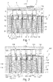
- Fig. 1 shows an electric heater 1 according to the state of the art.
- the electric heater 1 comprises an electronic controller 2, which is used to control the electric heater 1. Therefore the electronic controller 2 controls the power consumption of the electric heater 1 and/or the temperature of heating elements 7 of the electric heater 1.
- the electric heater 1 comprises a heater core 3 and a frame element 4 framing the heater core 3.
- the electronic controller 2 is electrically connected to a power supply which not shown in Fig. 1 .
- a plurality of electric connectors 6 is shown at a first short side 5 of the electronic controller 2, which is facing towards the heater core 3.
- the electric connectors 6 are electrically connected to either a positive pole of the power supply or a negative pole of the power supply.
- the electric connectors 6 that are electrically connected to a positive pole of the power supply and the electric connectors 6 that are electrically connected to a negative pole of the power supply are arranged in an alternating order parallel to the elongation direction E of the first short side 5 of the electronic controller 2.
- the heater core 3 comprises a plurality of electric heating elements 7 which comprise contact sheets 8.
- the contact sheets 8 are either electrically connected to an electric connector 6 or electrically connected to an adjacent contact sheet 8.
- the electrical connection between the contact sheets 8 is created through radiator elements 9, which are arranged between the electric heating elements 7.
- the contact sheets 8 and the radiator elements 9 are made of a conductive material.
- PTC-elements 10 which are arranged between the contact sheets 8, are connected to the power supply of an electrical circuit, e.g. of a closed electrical circuit.
- the PTC-elements 10 can generate heat by applying an electric voltage creating an electric current through the PTC-elements.
- the inventive electric heater 1 might be for example utilised as an auxiliary heater or pre-heater in a heating or in an air-conditioning system of a motor vehicle.
- the electric heater 1 heats up air, which flows in a flow direction F through interstices 11 formed by the radiator elements 9 of the electric heater 1 in order to heat up the air and to supply the passenger compartment of the motor vehicle with heated air.
- the heating or the air-conditioning system usually comprises a housing which is not illustrated in Fig. 1 .
- the housing comprises air ducts that are formed by walls of the housing.
- a fan is used to generate the air flow, wherein the air is sucked from the environment or/and out of the passenger compartment of the motor vehicle and it is blown through the housing such that the air of the air flow will subsequently be heated up by the heater core 3.
- the number and size of the electric heating elements 7 can vary in different embodiments.
- the contact sheets 8 have first ends 12, which are pointing towards the electronic controller 2 and second ends, which are not shown in Fig. 1 , opposite the first ends 12.
- the first ends 12 of the contact sheets 8 are secured in the frame element 4 by crimping connections 13 or clip connections which is not shown in Fig. 1 .
- the contact sheets 8 are arranged perpendicular to the first short side 5 of the electronic controller 2 and they are arranged parallel to a first long lateral side 14 of the heater core 3 and to a second long lateral side 15 of the heater core 3 which is arranged opposite the first long lateral side 14 of the heater core 3.
- the contact sheets 8 are arranged in a row which extends from the first long lateral side 14 of the heater core 3 to the second long lateral side 15 of the heater core 3.
- a first outwardly contact sheet 16 is arranged at the first long lateral side 14 of the heater core 3 and a second outwardly contact sheet 17 is arranged at the second long lateral side 15 of the heater core 3.
- the first end 12 of the first outwardly contact sheet 16 is directly connected to one of the electric connectors 6.
- the first end 12 of the second outwardly contact sheet 17 is secured to the frame element 4 by a crimping connection 13.
- the first outwardly contact sheet 16 comprises a first outer side 18 facing away from the heater core 3 and a first inner side 19 opposite the first outer side 18.
- the first outer side 18 is connected to an inner rim 20 of the frame element 4, particularly by gluing.
- the first inner side 19 of the first outwardly contact sheet 16 is connected to a first radiator element 21 by gluing or soldering.
- the first radiator element 21 is arranged adjacent to the first long lateral side 14 of the heater core 3.
- the second outwardly contact sheet 17 comprises a second outer side 22 facing away from the heater core 3 and a second inner side 23 opposite the second outer side 22.
- the second outer side 22 is connected to the inner rim 20 of the frame element 4, particularly by gluing.
- the second inner side 23 of the second outwardly contact sheet 17 is connected to a second radiator element 24 by gluing or soldering.
- the second radiator element 24 is arranged adjacent to the second long lateral side 15 of the heater core 3.
- Fig. 2 shows a view of first embodiment of an inventive electric heater 101.
- the electric heater 101 comprises an electronic controller 102, which is used to control the electric heater 101. Furthermore, the electric heater 101 comprises a heater core 103 and a frame element 104, which is framing the heater core 103.
- the electronic controller 102 comprises a housing 124 which is connected to the frame element 104 by clip connections, which are not shown in Fig. 2 .
- the electronic controller 102 can be electrically connected to a power supply what is not shown in Fig. 2 .
- a plurality of electric connectors 106 is shown at a first short side 105 of the electronic controller 102, which is facing towards the heater core 103.
- the electric connectors 106 are electrically connected to either a positive pole of the power supply or a negative pole of the power supply or to a mass potential.
- the electric connectors 106 that are electrically connected to a positive pole of the power supply and the electric connectors 106 that are electrically connected to a negative pole of the power supply or to a mass potential are arranged in an alternating order parallel to the elongation direction E of the first short side 105 of the electronic controller 102.
- the inventive electric heater 101 might be for example utilised as an auxiliary heater or pre-heater in a heating or an air-conditioning system of a motor vehicle.
- the electric heater 101 heats up air of an air flow, which passes the heat transfer surface of the electric heater 101 in order to supply the passenger compartment of the motor vehicle with heated air into.
- the heating or the air-conditioning system usually comprises a housing which is not illustrated in Fig. 2 .
- the housing comprises air ducts that are formed by walls of the housing.
- a fan is used to generate an air flow, wherein the air is sucked from the environment or/and out of the passenger compartment of the motor vehicle and blown through the housing such that the air of the air flow will subsequently be heated up by the electric heater 101.
- the air In the flow direction F of the air flow after the electric heater 101 the air is directed through ducts and leaves the housing at ejector means into the passenger compartment.
- the heat transfer surface of the electric heater 101 is substantially provided by contact sheets 108 of electric heating elements 107 and by radiator elements 109 abutting to the contact sheets 108.
- the electric heating elements 107 with the contact sheets 108 and the radiator elements 109 are comprised by the heater core 103.
- the electric heating elements 107 respectively comprise two contact sheets 108 which are arranged adjacent to each other. The number and size of the electric heating elements 107 can vary in different embodiments.
- the electric heating elements 107 comprise PTC (positive temperature coefficient) -elements (110).
- PTC-elements 110 for example generated from a electrically conductive ceramic material, are conducting an electric current and conduct the electric current better at low temperatures than at high temperatures. The reason is, that their electrical resistance of the PTC material increases with rising temperature. Therefore the conducted electric current strength and thus the resulting heating power becomes lower with rising temperature.
- the electric heating elements 107 can be used to generate heat by applying an electric current to them. The electric current is obtained via the electric connectors 106 of the electronic controller 102.
- the heater core 103 comprises a first long lateral side 114 and a second long lateral side 115 opposite the first long lateral side 114. Additionally the heater core 103 comprises a first short lateral side 126 and a second short lateral side, which is not shown in Fig. 2 , opposite the first short lateral side 126. The first short lateral side 126 and the second short lateral side connect the first long lateral side 114 and the second long lateral side 115 of the heater core 103.
- the contact sheets 108 and the radiator elements 109 extend perpendicular to the flow direction F of the air flow and the first short lateral side 126 and extend parallel to the first long lateral side 114 and the second long lateral side 115 of the heater core 103 in an extension direction L.
- the contact sheets 108 are arranged in a row which extends from the first long lateral side 114 of the heater core 103 to the second long lateral side 115 of the heater core 103. Therefore, a first outwardly contact sheet 116 is arranged at the first long lateral side 114 of the heater core 103.
- the first outwardly contact sheet 116 comprises a first outer side 118 facing away from the heater core 103 and a first inner side 119 opposite the first outer side 118.
- the first outer side 118 is connected to the inner rim 120 of the frame element 104, particularly by gluing.
- the first inner side 119 of the first outwardly contact sheet 116 is connected to a first radiator element 121 by gluing or soldering.
- the first radiator element 121 is arranged adjacent to the first long lateral side 114 of the heater core 103.
- the first outwardly contact sheet 116 can be replaced by a first plastic strip which has a first base body comprising the same shape as the contact sheets 108, 116.
- the first plastic strip comprises a first outer side and a first inner side, wherein the first outer side is connected to the inner rim 120 of the frame element 104, particularly by gluing, and the first inner side is connected to the first radiator element 121, particularly by gluing.
- the second long lateral side 115 of the heater core 103 is externally bounded by a second strip 128 of plastic material which is arranged at the second long lateral side 115 of the heater core 103.
- the second strip 128 of plastic material comprises a second base body 129 which has the same shape as the contact sheets 108, 116.
- the second strip 128 of plastic material comprises a second outer side 130 facing away from the heater core 103 and a second inner side 131 opposite the second outer side 130.
- the second outer side 130 of the second strip 128 of plastic material is connected to the inner rim 120 of the frame element 104, particularly by gluing.
- the second inner side 131 of the second strip 128 of plastic material is connected to a second radiator element 124 by gluing or soldering.
- the second radiator element 124 is arranged adjacent to the second long lateral side 115 of the heater core 103.
- the heater core 103 is framed by the frame element 104 which can for example be made out of plastic material.
- the frame element 104 can comprise different sizes according to the construction requirements of the heating or the air-conditioning system.
- the entire extend of the heater core 103 projects perpendicular to the flow direction F of the air flow into an air duct, not shown in Fig. 2 , of the heating or the air-conditioning system.
- the frame element 104 comprises a plurality of through openings 127 which can be flowed through by the air flow. Thereby, the flow resistance caused by the frame element 104 is reduced.
- the frame element 104 comprises an outer edge, not shown in Fig. 2 , facing away from the heater core 103.
- the outer edge of the frame element 104 is attached fluid-tightly to the inner wall, not shown in Fig. 2 , of the air duct.
- a sealing element for example made out of plastic foam, not show in Fig. 2 , can be attached to the outer edge of the frame element 104.
- Fig. 3 shows the heater core 103 of the electric heater according to Fig. 2 .
- the heater core 103 comprises a first long lateral side 114 and a second long lateral side 115 opposite the first long lateral side 114. Additionally the heater core 103 comprises a first short lateral side 126 and a second short lateral side, not shown in Fig. 3 , opposite the first short lateral side 126.
- the first short lateral side 126 and the second short lateral side connect the first long lateral side 114 and the second long lateral side 115 of the heater core 103.
- the contact sheets 108 and the radiator elements 109 extend perpendicular to the flow direction F of the air flow and perpendicular to the first short lateral side 126 of the heater core 103 and extend parallel to the first long lateral side 114 and the second long lateral side 115 of the heater core 103 in an extension direction L. Therefore, the contact sheets 108 are arranged in a row which extends from the first long lateral side 114 of the heater core 103 to the second long lateral side 115 of the heater core 103. Therefore, a first outwardly contact sheet 116 is arranged at the first long lateral side 114 of the heater core 103.
- the first outwardly contact 116 sheet comprises a first outer side 118 facing away from the heater core 103 and a first inner side 119 opposite the first outer side 118.
- the first outer side 118 is connected to the inner rim of a frame element, not shown in Fig. 3 , particularly by gluing.
- the first inner side 119 of the first outwardly contact sheet 116 is connected to a first radiator element 121 by gluing or soldering.
- the first radiator element 121 is arranged adjacent to the first long lateral side 114 of the heater core 103.
- the first outwardly contact sheet 116 can be replaced by a first strip of plastic material which has a first base body comprising the same shape as the contact sheets 108, 116.
- the first strip of plastic material comprises a first outer side and a first inner side, wherein in the assembled state of the heater core 103, the first outer side is connected to the inner rim of the frame element, particularly by gluing, and the first inner side is connected to the first radiator element 121, particularly by gluing.
- the second long lateral side 115 of the heater core 103 is externally bounded by a second strip 128 of plastic material which is arranged at the second long lateral side 115 of the heater core 103.
- the second strip 128 of plastic material comprises a second base body 129 which has the same shape as the contact sheets 108,116.
- the second strip 128 of plastic material comprises a second outer side 130 which is facing away from the heater core 103 and a second inner side 131 opposite the second outer side 130.
- the second outer side 130 of the second strip 128 of plastic material is connected to the inner rim of the frame element, particularly by gluing.
- the second inner side 131 of the second strip 128 of plastic material is connected to a second radiator element 124, particularly by gluing.
- the second radiator element 124 is arranged adjacent to the second long lateral side 115 of the heater core 103.
Landscapes
- Engineering & Computer Science (AREA)
- Physics & Mathematics (AREA)
- Thermal Sciences (AREA)
- Chemical & Material Sciences (AREA)
- Combustion & Propulsion (AREA)
- Mechanical Engineering (AREA)
- General Engineering & Computer Science (AREA)
- Air-Conditioning For Vehicles (AREA)
Abstract
Description
- The invention relates to an electric heater, in particular for a heating or an air-conditioning system of a motor vehicle, with a heater core comprising a plurality of electric heating elements comprising contact sheets, said heater core further comprising a plurality of radiator elements, wherein the heater core comprising a first long lateral side and a second long lateral side opposite the first long lateral side, wherein the electric heating elements and the radiator elements are arranged parallel to each other and they are arranged parallel to the first long lateral side and to the second long lateral side of the heater core.
- Electric heaters are well known in the art especially for the use as an auxiliary heater in a heating or an air-conditioning system of a motor vehicle. The electric heater is used for example to heat up an air flow generated by a fan of the heating or the air-conditioning system. Such electric heaters often comprise a plurality of electric heating elements which comprise contact sheets and which are controlled by an electronic controller unit. The electric heating elements are arranged in a heater core together with a plurality of heat dissipating radiator elements which abut against the contact sheets of the electric heating elements. The heater core usually comprises a first long lateral side and a second long lateral side opposite the first long lateral side. The first long lateral side and the second long lateral side respectively comprise lateral contact sheets, which are for example made of aluminium or of an aluminium alloy. However, aluminium is a relatively expensive material. Furthermore, the weight of aluminium is relatively high, for example compared to synthetic materials like plastic.
- The
document EP 2 017 103 A1 discloses an electric heater which comprises a heater core which is arranged in a housing defining opposite frame face sides and which includes parallel layers of heat dissipating radiator elements and electric heating elements. Furthermore, the electric heater comprises a grid arrangement covering the respective frame face sides and reinforcing the housing. - The document
DE 44 34 613 A1 discloses an electric heater, in particular for a heating or an air-conditioning system of a motor vehicle, with a frame element and a plurality of electric heating elements assembled as a heater core and fastened to the frame element. The electric heating elements are arranged parallel to each other and each electric heating element comprises two contact sheets and PTC-elements arranged between the two contact sheets. A plurality of radiator elements, which are in heat-conductive connection with the electric heating elements, are additionally disclosed. In the electric heater, the contact sheets include angled-off sections essentially in a form of an L. The angled-off sections are connected to each other in a frictionally locking manner. The angled-off sections of the contact sheets are arranged at opposite ends of the electric heating element and are angled in opposite directions. The length of the angled-off sections of the contact sheets are dimensioned such that angled-off sections of one pair of contact sheets are in mutual abutment with angled-off sections of respectively adjacent pairs of contact sheets. - Therefore it is the object of the invention to provide an electric heater which is relatively lightweight and which can be manufactured at lower cost.
- The object is achieved by an electric heater according the features of
claim 1. - According to an embodiment of the invention an electric heater is provided, in particular for a heating or an air-conditioning system of a motor vehicle, with a heater core comprising a plurality of electric heating elements comprising contact sheets, said heater core further comprising a plurality of radiator elements, wherein the heater core comprises a first long lateral side and a second long lateral side opposite the first long lateral side, wherein the electric heating elements and the radiator elements are arranged parallel to each other and they are arranged parallel to the first long lateral side and to the second long lateral side of the heater core, wherein the heater core comprises a first strip of plastic material which is arranged at the first long lateral side of the heater core and/or a second strip of plastic material which is arranged at the second long lateral side of the heater core. The first strip of plastic material and the second strip of plastic material substitute the commonly used lateral contact sheets which are for example made of aluminum. Thereby, the manufacturing cost and the weight of the heater core are reduced.
- According to an advantageous embodiment of the invention, the first long lateral side of the heater core is outwardly bounded by the first strip of plastic material and/or the second long lateral side of the heater core is outwardly bounded by the second strip of plastic material. This feature enhances the stability of the heater core due to the lateral located at least one strip of plastic material.
- In a further advantageous embodiment, the first strip of plastic material comprises a first base body and the second strip of plastic material comprises a second base body, wherein the first base body and the second base body substantially comprise the same shape as the contact sheets of the electric heating elements. Thereby, the present manufacturing process of the heater core has not to be changed substantially in order to implement the inventive electric heater into the manufacturing line.
- It is preferable, if at least one frame element is connected to the first strip of plastic material and/or the second strip of plastic material. The at least one frame element helps to adapt differently sized heater cores to a large variety of different heating or air-conditioning systems with different air flow channels.
- In a further embodiment, the first strip of plastic material comprises a first outer side which is facing away from the heater core and the second strip of plastic material comprises a second outer side which is facing away from the heater core, wherein at least one of the frame elements is connected to the first outer side and/or the second outer side.
- Additionally the first strip of plastic material comprises a first inner side facing towards the heater core and the second strip of plastic material comprises a second inner side facing towards the heater core, wherein the first inner side is connected to a first radiator element, particularly by gluing, and the second inner side is connected to a second radiator element, particularly by gluing, wherein the first radiator element is arranged adjacent to the first long lateral side of the heater core and the second radiator element is arranged adjacent to the second long lateral side of the heater core.
- Furthermore it is preferable, that at least one of the electric heating elements comprises at least one PTC-element. In another embodiment a plurality of PTC-elements are provided in each of the heating elements.
- In a further embodiment it is favorable that the at least one frame element comprises an inner rim with a first longitudinal side and a second longitudinal side opposite the first longitudinal side, wherein the first longitudinal side of the inner rim is connected to the first plastic strip, particularly by gluing and the second longitudinal side of the inner rim is connected to the second plastic strip, particularly by gluing.
- Furthermore it is advantageous that the heater core comprises a first short lateral side which is arranged perpendicular to the first long lateral side and the second long lateral side of the heater core, wherein an electronic controller is arranged at the first short lateral side of the heater core.
- In a further embodiment of the invention, the electronic controller comprises electric connectors which are electrically connected to either a positive pole of a power supply or a negative pole of a power supply or a mass potential and particularly arranged in an alternating order, wherein the electric heating elements are electrically connected to the electric connectors.
- In a further advantageous embodiment, the electronic controller comprises a housing, wherein the at least one frame element is connected to the housing of the electronic controller by at least one clip connection.
- In another embodiment it is favorable that the at least one frame element frames the heater core. Therefore the heater core is protected against lateral forces during e.g. assembling.
- Further preferable embodiments of the invention are described in the claims and the following description of the drawings.
- The invention is explained in detail below by means of an exemplary embodiment and with reference to the drawings, in which:
- Fig.1
- shows an electric heater according to the state of the art,
- Fig. 2
- shows a first embodiment of an inventive electric heater, and
- Fig. 3
- shows a heater core of the electric heater according to
Fig. 2 . -
Fig. 1 shows anelectric heater 1 according to the state of the art. Theelectric heater 1 comprises anelectronic controller 2, which is used to control theelectric heater 1. Therefore theelectronic controller 2 controls the power consumption of theelectric heater 1 and/or the temperature ofheating elements 7 of theelectric heater 1. - The
electric heater 1 comprises a heater core 3 and aframe element 4 framing the heater core 3. Theelectronic controller 2 is electrically connected to a power supply which not shown inFig. 1 . - At a first
short side 5 of theelectronic controller 2, which is facing towards the heater core 3, a plurality ofelectric connectors 6 is shown. Theelectric connectors 6 are electrically connected to either a positive pole of the power supply or a negative pole of the power supply. Theelectric connectors 6 that are electrically connected to a positive pole of the power supply and theelectric connectors 6 that are electrically connected to a negative pole of the power supply are arranged in an alternating order parallel to the elongation direction E of the firstshort side 5 of theelectronic controller 2. The heater core 3 comprises a plurality ofelectric heating elements 7 which comprisecontact sheets 8. Thecontact sheets 8 are either electrically connected to anelectric connector 6 or electrically connected to anadjacent contact sheet 8. The electrical connection between thecontact sheets 8 is created throughradiator elements 9, which are arranged between theelectric heating elements 7. Thecontact sheets 8 and theradiator elements 9 are made of a conductive material. Through the electrical connection of thecontact sheets 8 withadjacent contact sheets 8 or with theelectric connectors 6, it is realized, that PTC-elements 10, which are arranged between thecontact sheets 8, are connected to the power supply of an electrical circuit, e.g. of a closed electrical circuit. Thus the PTC-elements 10 can generate heat by applying an electric voltage creating an electric current through the PTC-elements. - The inventive
electric heater 1 might be for example utilised as an auxiliary heater or pre-heater in a heating or in an air-conditioning system of a motor vehicle. In this case theelectric heater 1 heats up air, which flows in a flow direction F through interstices 11 formed by theradiator elements 9 of theelectric heater 1 in order to heat up the air and to supply the passenger compartment of the motor vehicle with heated air. - For this purpose the heating or the air-conditioning system usually comprises a housing which is not illustrated in
Fig. 1 . The housing comprises air ducts that are formed by walls of the housing. A fan is used to generate the air flow, wherein the air is sucked from the environment or/and out of the passenger compartment of the motor vehicle and it is blown through the housing such that the air of the air flow will subsequently be heated up by the heater core 3. - In the flow direction F of the air flow after the
electric heater 1 the air is directed through ducts and leaves the housing at ejector means into the passenger compartment. - The number and size of the
electric heating elements 7 can vary in different embodiments. Thecontact sheets 8 have first ends 12, which are pointing towards theelectronic controller 2 and second ends, which are not shown inFig. 1 , opposite the first ends 12. The first ends 12 of thecontact sheets 8 are secured in theframe element 4 by crimpingconnections 13 or clip connections which is not shown inFig. 1 . Thecontact sheets 8 are arranged perpendicular to the firstshort side 5 of theelectronic controller 2 and they are arranged parallel to a first long lateral side 14 of the heater core 3 and to a secondlong lateral side 15 of the heater core 3 which is arranged opposite the first long lateral side 14 of the heater core 3. Therefore, thecontact sheets 8 are arranged in a row which extends from the first long lateral side 14 of the heater core 3 to the secondlong lateral side 15 of the heater core 3. Thereby, a first outwardlycontact sheet 16 is arranged at the first long lateral side 14 of the heater core 3 and a second outwardly contact sheet 17 is arranged at the secondlong lateral side 15 of the heater core 3. Thefirst end 12 of the first outwardlycontact sheet 16 is directly connected to one of theelectric connectors 6. Thefirst end 12 of the second outwardly contact sheet 17 is secured to theframe element 4 by a crimpingconnection 13. - The first outwardly
contact sheet 16 comprises a firstouter side 18 facing away from the heater core 3 and a first inner side 19 opposite the firstouter side 18. The firstouter side 18 is connected to aninner rim 20 of theframe element 4, particularly by gluing. The first inner side 19 of the first outwardlycontact sheet 16 is connected to afirst radiator element 21 by gluing or soldering. Thefirst radiator element 21 is arranged adjacent to the first long lateral side 14 of the heater core 3. - The second outwardly contact sheet 17 comprises a second
outer side 22 facing away from the heater core 3 and a secondinner side 23 opposite the secondouter side 22. The secondouter side 22 is connected to theinner rim 20 of theframe element 4, particularly by gluing. The secondinner side 23 of the second outwardly contact sheet 17 is connected to asecond radiator element 24 by gluing or soldering. Thesecond radiator element 24 is arranged adjacent to the secondlong lateral side 15 of the heater core 3. -
Fig. 2 shows a view of first embodiment of an inventiveelectric heater 101. Theelectric heater 101 comprises anelectronic controller 102, which is used to control theelectric heater 101. Furthermore, theelectric heater 101 comprises aheater core 103 and aframe element 104, which is framing theheater core 103. - The
electronic controller 102 comprises ahousing 124 which is connected to theframe element 104 by clip connections, which are not shown inFig. 2 . Theelectronic controller 102 can be electrically connected to a power supply what is not shown inFig. 2 . At a firstshort side 105 of theelectronic controller 102, which is facing towards theheater core 103, a plurality ofelectric connectors 106 is shown. Theelectric connectors 106 are electrically connected to either a positive pole of the power supply or a negative pole of the power supply or to a mass potential. Theelectric connectors 106 that are electrically connected to a positive pole of the power supply and theelectric connectors 106 that are electrically connected to a negative pole of the power supply or to a mass potential are arranged in an alternating order parallel to the elongation direction E of the firstshort side 105 of theelectronic controller 102. - The inventive
electric heater 101 might be for example utilised as an auxiliary heater or pre-heater in a heating or an air-conditioning system of a motor vehicle. In this case theelectric heater 101 heats up air of an air flow, which passes the heat transfer surface of theelectric heater 101 in order to supply the passenger compartment of the motor vehicle with heated air into. For this purpose the heating or the air-conditioning system usually comprises a housing which is not illustrated inFig. 2 . The housing comprises air ducts that are formed by walls of the housing. A fan is used to generate an air flow, wherein the air is sucked from the environment or/and out of the passenger compartment of the motor vehicle and blown through the housing such that the air of the air flow will subsequently be heated up by theelectric heater 101. In the flow direction F of the air flow after theelectric heater 101 the air is directed through ducts and leaves the housing at ejector means into the passenger compartment. - The heat transfer surface of the
electric heater 101 is substantially provided bycontact sheets 108 ofelectric heating elements 107 and byradiator elements 109 abutting to thecontact sheets 108. Theelectric heating elements 107 with thecontact sheets 108 and theradiator elements 109 are comprised by theheater core 103. Theelectric heating elements 107 respectively comprise twocontact sheets 108 which are arranged adjacent to each other. The number and size of theelectric heating elements 107 can vary in different embodiments. - The
electric heating elements 107 comprise PTC (positive temperature coefficient) -elements (110). PTC-elements 110, for example generated from a electrically conductive ceramic material, are conducting an electric current and conduct the electric current better at low temperatures than at high temperatures. The reason is, that their electrical resistance of the PTC material increases with rising temperature. Therefore the conducted electric current strength and thus the resulting heating power becomes lower with rising temperature. Thus, theelectric heating elements 107 can be used to generate heat by applying an electric current to them. The electric current is obtained via theelectric connectors 106 of theelectronic controller 102. - The
heater core 103 comprises a first longlateral side 114 and a second longlateral side 115 opposite the first longlateral side 114. Additionally theheater core 103 comprises a first shortlateral side 126 and a second short lateral side, which is not shown inFig. 2 , opposite the first shortlateral side 126. The first shortlateral side 126 and the second short lateral side connect the first longlateral side 114 and the second longlateral side 115 of theheater core 103. Thecontact sheets 108 and theradiator elements 109 extend perpendicular to the flow direction F of the air flow and the first shortlateral side 126 and extend parallel to the first longlateral side 114 and the second longlateral side 115 of theheater core 103 in an extension direction L. Thereby, thecontact sheets 108 are arranged in a row which extends from the first longlateral side 114 of theheater core 103 to the second longlateral side 115 of theheater core 103. Therefore, a first outwardlycontact sheet 116 is arranged at the first longlateral side 114 of theheater core 103. The first outwardlycontact sheet 116 comprises a firstouter side 118 facing away from theheater core 103 and a firstinner side 119 opposite the firstouter side 118. The firstouter side 118 is connected to theinner rim 120 of theframe element 104, particularly by gluing. The firstinner side 119 of the first outwardlycontact sheet 116 is connected to afirst radiator element 121 by gluing or soldering. Thefirst radiator element 121 is arranged adjacent to the first longlateral side 114 of theheater core 103. - In an alternative embodiment the first outwardly
contact sheet 116 can be replaced by a first plastic strip which has a first base body comprising the same shape as thecontact sheets inner rim 120 of theframe element 104, particularly by gluing, and the first inner side is connected to thefirst radiator element 121, particularly by gluing. - In the embodiment shown in
Fig. 2 the second longlateral side 115 of theheater core 103 is externally bounded by asecond strip 128 of plastic material which is arranged at the second longlateral side 115 of theheater core 103. Thesecond strip 128 of plastic material comprises asecond base body 129 which has the same shape as thecontact sheets second strip 128 of plastic material comprises a secondouter side 130 facing away from theheater core 103 and a secondinner side 131 opposite the secondouter side 130. The secondouter side 130 of thesecond strip 128 of plastic material is connected to theinner rim 120 of theframe element 104, particularly by gluing. The secondinner side 131 of thesecond strip 128 of plastic material is connected to asecond radiator element 124 by gluing or soldering. Thesecond radiator element 124 is arranged adjacent to the second longlateral side 115 of theheater core 103. - The
heater core 103 is framed by theframe element 104 which can for example be made out of plastic material. In different embodiments, theframe element 104 can comprise different sizes according to the construction requirements of the heating or the air-conditioning system. The entire extend of theheater core 103 projects perpendicular to the flow direction F of the air flow into an air duct, not shown inFig. 2 , of the heating or the air-conditioning system. Theframe element 104 comprises a plurality of throughopenings 127 which can be flowed through by the air flow. Thereby, the flow resistance caused by theframe element 104 is reduced. - The
frame element 104 comprises an outer edge, not shown inFig. 2 , facing away from theheater core 103. The outer edge of theframe element 104 is attached fluid-tightly to the inner wall, not shown inFig. 2 , of the air duct. To enhance fluid-tightness and in order to compensate for tolerances a sealing element, for example made out of plastic foam, not show inFig. 2 , can be attached to the outer edge of theframe element 104. -
Fig. 3 shows theheater core 103 of the electric heater according toFig. 2 . Theheater core 103 comprises a first longlateral side 114 and a second longlateral side 115 opposite the first longlateral side 114. Additionally theheater core 103 comprises a first shortlateral side 126 and a second short lateral side, not shown inFig. 3 , opposite the first shortlateral side 126. The first shortlateral side 126 and the second short lateral side connect the first longlateral side 114 and the second longlateral side 115 of theheater core 103. Thecontact sheets 108 and theradiator elements 109 extend perpendicular to the flow direction F of the air flow and perpendicular to the first shortlateral side 126 of theheater core 103 and extend parallel to the first longlateral side 114 and the second longlateral side 115 of theheater core 103 in an extension direction L. Therefore, thecontact sheets 108 are arranged in a row which extends from the first longlateral side 114 of theheater core 103 to the second longlateral side 115 of theheater core 103. Therefore, a first outwardlycontact sheet 116 is arranged at the first longlateral side 114 of theheater core 103. The first outwardly contact 116 sheet comprises a firstouter side 118 facing away from theheater core 103 and a firstinner side 119 opposite the firstouter side 118. - In the assembled state of the electric heater, the first
outer side 118 is connected to the inner rim of a frame element, not shown inFig. 3 , particularly by gluing. The firstinner side 119 of the first outwardlycontact sheet 116 is connected to afirst radiator element 121 by gluing or soldering. Thefirst radiator element 121 is arranged adjacent to the first longlateral side 114 of theheater core 103. - In alternative embodiments, the first outwardly
contact sheet 116 can be replaced by a first strip of plastic material which has a first base body comprising the same shape as thecontact sheets heater core 103, the first outer side is connected to the inner rim of the frame element, particularly by gluing, and the first inner side is connected to thefirst radiator element 121, particularly by gluing. - In the embodiment shown in
Fig. 3 the second longlateral side 115 of theheater core 103 is externally bounded by asecond strip 128 of plastic material which is arranged at the second longlateral side 115 of theheater core 103. Thesecond strip 128 of plastic material comprises asecond base body 129 which has the same shape as the contact sheets 108,116. Thesecond strip 128 of plastic material comprises a secondouter side 130 which is facing away from theheater core 103 and a secondinner side 131 opposite the secondouter side 130. In the assembled state of the electric heater, the secondouter side 130 of thesecond strip 128 of plastic material is connected to the inner rim of the frame element, particularly by gluing. The secondinner side 131 of thesecond strip 128 of plastic material is connected to asecond radiator element 124, particularly by gluing. Thesecond radiator element 124 is arranged adjacent to the second longlateral side 115 of theheater core 103. - While the invention has been explained with reference to the Figures, it will be clear to those skilled in the arts to which it pertains that a variety of modifications and changes can be made thereto without departing from the scope of the invention.
Claims (12)
- Electric heater (1, 101) in particular for a heating or an air-conditioning system of a motor vehicle with a heater core (3, 103) comprising a plurality of electric heating elements (7, 107) with contact sheets (8, 16, 17, 108, 116) and with a plurality of radiator elements (9, 21, 24, 109, 121, 124), wherein the heater core (3, 103) comprises a first long lateral side (14, 114) and a second long lateral side (15, 115) opposite the first long lateral side (14, 114), wherein the electric heating elements (7, 107) and the radiator elements (9, 21, 24, 109, 121, 124) are arranged parallel to each other and are arranged parallel to the first long lateral side (14, 114) and the second long lateral side (15, 115) of the heater core (3, 103), characterised in that the heater core (3, 103) comprises a first strip of plastic material which is arranged at the first long lateral side (14, 114) of the heater core (3, 103) and/or a second strip (128) of plastic material which is arranged at the second long lateral side (15, 115) of the heater core (3, 103).
- Electric heater (1, 101) according to claim 1, characterised in that the first long lateral side (14, 114) of the heater core (3, 103) is bounded externally by the first strip of plastic material and/or the second long lateral side (15, 115) of the heater core (3, 103) is bounded externally by the second strip (128) of plastic material.
- Electric heater (1, 101) according to claim 1 or 2, characterised in that the first strip of plastic material comprises a first base body and the second strip (128) of plastic material comprises a second base body (129), wherein the first base body and the second base body (129) substantially comprise the same shape as the contact sheets (8, 16, 17, 108, 116) of the electric heating elements (7, 107).
- Electric heater (1, 101) according to claim 1, 2 or 3, characterised in that at least one frame element (4, 104) is connected to the first strip of plastic material and/or the second strip (128) of plastic material.
- Electric heater (1, 101) according to claim 4, characterised in that the first strip of plastic material comprises a first outer side which is facing away from the heater core (3, 103) and the second strip (128) of plastic material comprises a second outer side (130) which is facing away from the heater core (3, 103), wherein the at least one frame element (4, 104) is connected to the first outer side and/or the second outer side (130).
- Electric heater (1, 101) according to claim 1, 2, 3, 4 or 5, characterised in that the first strip of plastic material comprises a first inner side facing towards the heater core (3, 103) and the second strip (128) of plastic material comprises a second inner side (131) facing towards the heater core (3, 103), wherein the first inner side is connected to a first radiator element (21, 121), particularly by gluing, and the second inner side (131) is connected to a second radiator element (24, 124), particularly by gluing, wherein the first radiator element (21, 121) is arranged adjacent to the first long lateral side (14, 114) of the heater core (3, 103) and the second radiator element (24, 124) is arranged adjacent to the second long lateral side (15, 115) of the heater core (3, 103).
- Electric heater (1, 101) according to one of the previous claims, characterised in that at least one of the electric heating elements (7, 107) comprises at least one PTC-element (10, 110).
- Electric heater (1, 101) according to claim 4, 5, 6 or 7, characterised in that the at least one frame element (4, 104) comprises an inner rim (20, 120) with a first longitudinal side and a second longitudinal side opposite the first longitudinal side, wherein the first longitudinal side of the inner rim (20, 120) is connected to the first strip of plastic material and the second longitudinal side of the inner rim (20, 120) is connected to the second strip (128) of plastic material.
- Electric heater (1, 101) according to one of the previous claims, characterised in that the heater core (3, 103) comprises a first short lateral side (126) which is arranged perpendicular to the first long lateral side (14, 114) and the second long lateral side (15, 115) of the heater core (3, 103), wherein an electronic controller (2, 102) is arranged at the first short lateral side (126) of the heater core (3, 103).
- Electric heater (1, 101) according to one of the previous claims, characterised in that the electronic controller (2, 102) comprises electric connectors (6, 106) which are electrically connected to either a positive pole of a power supply or a negative pole of a power supply and arranged in an alternating order, wherein the electric heating elements (7, 107) are electrically connected to the electric connectors (6, 106).
- Electric heater (1, 101) according to one of the claims 4 to 10, characterised in that the electronic controller (2, 102) comprises a housing (125), wherein the at least one frame element (4, 104) is connected to the housing (125) of the electronic controller (2, 102) by at least one clip connection.
- Electric heater (1, 101) according to one of the claims 4 to 11, characterised in that the at least one frame element (4, 104) frames the heater core (3, 103).
Priority Applications (1)
| Application Number | Priority Date | Filing Date | Title |
|---|---|---|---|
| EP16189040.5A EP3296660A1 (en) | 2016-09-15 | 2016-09-15 | Electric heater |
Applications Claiming Priority (1)
| Application Number | Priority Date | Filing Date | Title |
|---|---|---|---|
| EP16189040.5A EP3296660A1 (en) | 2016-09-15 | 2016-09-15 | Electric heater |
Publications (1)
| Publication Number | Publication Date |
|---|---|
| EP3296660A1 true EP3296660A1 (en) | 2018-03-21 |
Family
ID=56958767
Family Applications (1)
| Application Number | Title | Priority Date | Filing Date |
|---|---|---|---|
| EP16189040.5A Withdrawn EP3296660A1 (en) | 2016-09-15 | 2016-09-15 | Electric heater |
Country Status (1)
| Country | Link |
|---|---|
| EP (1) | EP3296660A1 (en) |
Cited By (1)
| Publication number | Priority date | Publication date | Assignee | Title |
|---|---|---|---|---|
| EP4257907A3 (en) * | 2020-05-04 | 2023-11-15 | Kraftanlagen Energies & Services GmbH | Heating device, heating system, heat storage device and heat storage system |
Citations (5)
| Publication number | Priority date | Publication date | Assignee | Title |
|---|---|---|---|---|
| DE9407104U1 (en) * | 1994-04-29 | 1994-10-13 | Sunlead Electrical Corp., Taipeh/T'ai-pei | Heater |
| DE4434613A1 (en) | 1994-09-28 | 1996-04-04 | Behr Gmbh & Co | Electric heating device, in particular for a motor vehicle |
| DE10229547A1 (en) * | 2002-07-01 | 2004-01-15 | Att Automotive Thermo Tech Gmbh | Device for direct electric air heating has resistance consisting of two or more layers of zigzag strips of folded heating ribs separated by intermediate layers of electrically insulating material |
| EP2017103A1 (en) | 2007-07-18 | 2009-01-21 | Catem GmbH & Co. KG | Electric heating device |
| EP2730854A1 (en) * | 2012-11-12 | 2014-05-14 | Betacera Inc. | Car interior compartment heater |
-
2016
- 2016-09-15 EP EP16189040.5A patent/EP3296660A1/en not_active Withdrawn
Patent Citations (5)
| Publication number | Priority date | Publication date | Assignee | Title |
|---|---|---|---|---|
| DE9407104U1 (en) * | 1994-04-29 | 1994-10-13 | Sunlead Electrical Corp., Taipeh/T'ai-pei | Heater |
| DE4434613A1 (en) | 1994-09-28 | 1996-04-04 | Behr Gmbh & Co | Electric heating device, in particular for a motor vehicle |
| DE10229547A1 (en) * | 2002-07-01 | 2004-01-15 | Att Automotive Thermo Tech Gmbh | Device for direct electric air heating has resistance consisting of two or more layers of zigzag strips of folded heating ribs separated by intermediate layers of electrically insulating material |
| EP2017103A1 (en) | 2007-07-18 | 2009-01-21 | Catem GmbH & Co. KG | Electric heating device |
| EP2730854A1 (en) * | 2012-11-12 | 2014-05-14 | Betacera Inc. | Car interior compartment heater |
Cited By (1)
| Publication number | Priority date | Publication date | Assignee | Title |
|---|---|---|---|---|
| EP4257907A3 (en) * | 2020-05-04 | 2023-11-15 | Kraftanlagen Energies & Services GmbH | Heating device, heating system, heat storage device and heat storage system |
Similar Documents
| Publication | Publication Date | Title |
|---|---|---|
| US20070029253A1 (en) | Electrical heating module for air flow heating, in particular for heating and ventilation of seats | |
| US7627234B2 (en) | Electrical heating device, particularly for an automobile vehicle | |
| US20090255914A1 (en) | Heat-generating element and heating device comprising the same | |
| JP6301836B2 (en) | Insulating heating module for auxiliary heating device | |
| EP3584808B1 (en) | Ptc heating module for heating a fluid | |
| CN106162955B (en) | Electric heating device | |
| CN1987287B (en) | Optimization of the heating unit | |
| US20210153306A1 (en) | Heating module | |
| EP3299743B1 (en) | Electric heater | |
| CN109693514A (en) | Electric heater for motor vehicles | |
| US7098429B2 (en) | Heat exchanger, particularly for a heating or air conditioning unit in a motor vehicle | |
| JP4966853B2 (en) | A heating device having a heating element especially for automobiles | |
| CN107791786A (en) | Electric heating equipment | |
| CN115707155A (en) | Heating rod | |
| CN108292698A (en) | Thermoelectric heat exchanger | |
| EP2969673B1 (en) | Defroster and vehicle having the same | |
| EP3291640A1 (en) | Electric heater | |
| US9555690B2 (en) | Heating device composed of heating modules, and heating module for same | |
| JP2008536749A (en) | Electric auxiliary heater for automotive heating or air conditioning | |
| EP3401617A1 (en) | Electric heater | |
| US20150300686A1 (en) | Heat sink, associated heating module and corresponding assembly method | |
| CN103884092B (en) | Vehicle heater and its manufacture method | |
| US20180160483A1 (en) | Heating module and electric heating device comprising such a heating module | |
| CN110290605B (en) | Heating device | |
| EP3287710A1 (en) | Electric heater |
Legal Events
| Date | Code | Title | Description |
|---|---|---|---|
| PUAI | Public reference made under article 153(3) epc to a published international application that has entered the european phase |
Free format text: ORIGINAL CODE: 0009012 |
|
| STAA | Information on the status of an ep patent application or granted ep patent |
Free format text: STATUS: THE APPLICATION HAS BEEN PUBLISHED |
|
| AK | Designated contracting states |
Kind code of ref document: A1 Designated state(s): AL AT BE BG CH CY CZ DE DK EE ES FI FR GB GR HR HU IE IS IT LI LT LU LV MC MK MT NL NO PL PT RO RS SE SI SK SM TR |
|
| AX | Request for extension of the european patent |
Extension state: BA ME |
|
| STAA | Information on the status of an ep patent application or granted ep patent |
Free format text: STATUS: REQUEST FOR EXAMINATION WAS MADE |
|
| 17P | Request for examination filed |
Effective date: 20180921 |
|
| RBV | Designated contracting states (corrected) |
Designated state(s): AL AT BE BG CH CY CZ DE DK EE ES FI FR GB GR HR HU IE IS IT LI LT LU LV MC MK MT NL NO PL PT RO RS SE SI SK SM TR |
|
| STAA | Information on the status of an ep patent application or granted ep patent |
Free format text: STATUS: THE APPLICATION IS DEEMED TO BE WITHDRAWN |
|
| 18D | Application deemed to be withdrawn |
Effective date: 20210401 |