EP3296592A1 - Power transmission system for motor vehicle and motor vehicle - Google Patents
Power transmission system for motor vehicle and motor vehicle Download PDFInfo
- Publication number
- EP3296592A1 EP3296592A1 EP17186800.3A EP17186800A EP3296592A1 EP 3296592 A1 EP3296592 A1 EP 3296592A1 EP 17186800 A EP17186800 A EP 17186800A EP 3296592 A1 EP3296592 A1 EP 3296592A1
- Authority
- EP
- European Patent Office
- Prior art keywords
- gears
- gear
- coupling
- pair
- vehicle
- Prior art date
- Legal status (The legal status is an assumption and is not a legal conclusion. Google has not performed a legal analysis and makes no representation as to the accuracy of the status listed.)
- Withdrawn
Links
Images

Classifications
-
- B—PERFORMING OPERATIONS; TRANSPORTING
- B60—VEHICLES IN GENERAL
- B60K—ARRANGEMENT OR MOUNTING OF PROPULSION UNITS OR OF TRANSMISSIONS IN VEHICLES; ARRANGEMENT OR MOUNTING OF PLURAL DIVERSE PRIME-MOVERS IN VEHICLES; AUXILIARY DRIVES FOR VEHICLES; INSTRUMENTATION OR DASHBOARDS FOR VEHICLES; ARRANGEMENTS IN CONNECTION WITH COOLING, AIR INTAKE, GAS EXHAUST OR FUEL SUPPLY OF PROPULSION UNITS IN VEHICLES
- B60K6/00—Arrangement or mounting of plural diverse prime-movers for mutual or common propulsion, e.g. hybrid propulsion systems comprising electric motors and internal combustion engines ; Control systems therefor, i.e. systems controlling two or more prime movers, or controlling one of these prime movers and any of the transmission, drive or drive units Informative references: mechanical gearings with secondary electric drive F16H3/72; arrangements for handling mechanical energy structurally associated with the dynamo-electric machine H02K7/00; machines comprising structurally interrelated motor and generator parts H02K51/00; dynamo-electric machines not otherwise provided for in H02K see H02K99/00
- B60K6/20—Arrangement or mounting of plural diverse prime-movers for mutual or common propulsion, e.g. hybrid propulsion systems comprising electric motors and internal combustion engines ; Control systems therefor, i.e. systems controlling two or more prime movers, or controlling one of these prime movers and any of the transmission, drive or drive units Informative references: mechanical gearings with secondary electric drive F16H3/72; arrangements for handling mechanical energy structurally associated with the dynamo-electric machine H02K7/00; machines comprising structurally interrelated motor and generator parts H02K51/00; dynamo-electric machines not otherwise provided for in H02K see H02K99/00 the prime-movers consisting of electric motors and internal combustion engines, e.g. HEVs
- B60K6/42—Arrangement or mounting of plural diverse prime-movers for mutual or common propulsion, e.g. hybrid propulsion systems comprising electric motors and internal combustion engines ; Control systems therefor, i.e. systems controlling two or more prime movers, or controlling one of these prime movers and any of the transmission, drive or drive units Informative references: mechanical gearings with secondary electric drive F16H3/72; arrangements for handling mechanical energy structurally associated with the dynamo-electric machine H02K7/00; machines comprising structurally interrelated motor and generator parts H02K51/00; dynamo-electric machines not otherwise provided for in H02K see H02K99/00 the prime-movers consisting of electric motors and internal combustion engines, e.g. HEVs characterised by the architecture of the hybrid electric vehicle
- B60K6/48—Parallel type
-
- B—PERFORMING OPERATIONS; TRANSPORTING
- B60—VEHICLES IN GENERAL
- B60K—ARRANGEMENT OR MOUNTING OF PROPULSION UNITS OR OF TRANSMISSIONS IN VEHICLES; ARRANGEMENT OR MOUNTING OF PLURAL DIVERSE PRIME-MOVERS IN VEHICLES; AUXILIARY DRIVES FOR VEHICLES; INSTRUMENTATION OR DASHBOARDS FOR VEHICLES; ARRANGEMENTS IN CONNECTION WITH COOLING, AIR INTAKE, GAS EXHAUST OR FUEL SUPPLY OF PROPULSION UNITS IN VEHICLES
- B60K6/00—Arrangement or mounting of plural diverse prime-movers for mutual or common propulsion, e.g. hybrid propulsion systems comprising electric motors and internal combustion engines ; Control systems therefor, i.e. systems controlling two or more prime movers, or controlling one of these prime movers and any of the transmission, drive or drive units Informative references: mechanical gearings with secondary electric drive F16H3/72; arrangements for handling mechanical energy structurally associated with the dynamo-electric machine H02K7/00; machines comprising structurally interrelated motor and generator parts H02K51/00; dynamo-electric machines not otherwise provided for in H02K see H02K99/00
- B60K6/20—Arrangement or mounting of plural diverse prime-movers for mutual or common propulsion, e.g. hybrid propulsion systems comprising electric motors and internal combustion engines ; Control systems therefor, i.e. systems controlling two or more prime movers, or controlling one of these prime movers and any of the transmission, drive or drive units Informative references: mechanical gearings with secondary electric drive F16H3/72; arrangements for handling mechanical energy structurally associated with the dynamo-electric machine H02K7/00; machines comprising structurally interrelated motor and generator parts H02K51/00; dynamo-electric machines not otherwise provided for in H02K see H02K99/00 the prime-movers consisting of electric motors and internal combustion engines, e.g. HEVs
- B60K6/50—Architecture of the driveline characterised by arrangement or kind of transmission units
- B60K6/54—Transmission for changing ratio
- B60K6/547—Transmission for changing ratio the transmission being a stepped gearing
-
- F—MECHANICAL ENGINEERING; LIGHTING; HEATING; WEAPONS; BLASTING
- F16—ENGINEERING ELEMENTS AND UNITS; GENERAL MEASURES FOR PRODUCING AND MAINTAINING EFFECTIVE FUNCTIONING OF MACHINES OR INSTALLATIONS; THERMAL INSULATION IN GENERAL
- F16H—GEARING
- F16H3/00—Toothed gearings for conveying rotary motion with variable gear ratio or for reversing rotary motion
- F16H3/006—Toothed gearings for conveying rotary motion with variable gear ratio or for reversing rotary motion power being selectively transmitted by either one of the parallel flow paths
-
- B—PERFORMING OPERATIONS; TRANSPORTING
- B60—VEHICLES IN GENERAL
- B60K—ARRANGEMENT OR MOUNTING OF PROPULSION UNITS OR OF TRANSMISSIONS IN VEHICLES; ARRANGEMENT OR MOUNTING OF PLURAL DIVERSE PRIME-MOVERS IN VEHICLES; AUXILIARY DRIVES FOR VEHICLES; INSTRUMENTATION OR DASHBOARDS FOR VEHICLES; ARRANGEMENTS IN CONNECTION WITH COOLING, AIR INTAKE, GAS EXHAUST OR FUEL SUPPLY OF PROPULSION UNITS IN VEHICLES
- B60K6/00—Arrangement or mounting of plural diverse prime-movers for mutual or common propulsion, e.g. hybrid propulsion systems comprising electric motors and internal combustion engines ; Control systems therefor, i.e. systems controlling two or more prime movers, or controlling one of these prime movers and any of the transmission, drive or drive units Informative references: mechanical gearings with secondary electric drive F16H3/72; arrangements for handling mechanical energy structurally associated with the dynamo-electric machine H02K7/00; machines comprising structurally interrelated motor and generator parts H02K51/00; dynamo-electric machines not otherwise provided for in H02K see H02K99/00
- B60K6/20—Arrangement or mounting of plural diverse prime-movers for mutual or common propulsion, e.g. hybrid propulsion systems comprising electric motors and internal combustion engines ; Control systems therefor, i.e. systems controlling two or more prime movers, or controlling one of these prime movers and any of the transmission, drive or drive units Informative references: mechanical gearings with secondary electric drive F16H3/72; arrangements for handling mechanical energy structurally associated with the dynamo-electric machine H02K7/00; machines comprising structurally interrelated motor and generator parts H02K51/00; dynamo-electric machines not otherwise provided for in H02K see H02K99/00 the prime-movers consisting of electric motors and internal combustion engines, e.g. HEVs
- B60K6/42—Arrangement or mounting of plural diverse prime-movers for mutual or common propulsion, e.g. hybrid propulsion systems comprising electric motors and internal combustion engines ; Control systems therefor, i.e. systems controlling two or more prime movers, or controlling one of these prime movers and any of the transmission, drive or drive units Informative references: mechanical gearings with secondary electric drive F16H3/72; arrangements for handling mechanical energy structurally associated with the dynamo-electric machine H02K7/00; machines comprising structurally interrelated motor and generator parts H02K51/00; dynamo-electric machines not otherwise provided for in H02K see H02K99/00 the prime-movers consisting of electric motors and internal combustion engines, e.g. HEVs characterised by the architecture of the hybrid electric vehicle
- B60K6/48—Parallel type
- B60K2006/4825—Electric machine connected or connectable to gearbox input shaft
-
- B—PERFORMING OPERATIONS; TRANSPORTING
- B60—VEHICLES IN GENERAL
- B60K—ARRANGEMENT OR MOUNTING OF PROPULSION UNITS OR OF TRANSMISSIONS IN VEHICLES; ARRANGEMENT OR MOUNTING OF PLURAL DIVERSE PRIME-MOVERS IN VEHICLES; AUXILIARY DRIVES FOR VEHICLES; INSTRUMENTATION OR DASHBOARDS FOR VEHICLES; ARRANGEMENTS IN CONNECTION WITH COOLING, AIR INTAKE, GAS EXHAUST OR FUEL SUPPLY OF PROPULSION UNITS IN VEHICLES
- B60K6/00—Arrangement or mounting of plural diverse prime-movers for mutual or common propulsion, e.g. hybrid propulsion systems comprising electric motors and internal combustion engines ; Control systems therefor, i.e. systems controlling two or more prime movers, or controlling one of these prime movers and any of the transmission, drive or drive units Informative references: mechanical gearings with secondary electric drive F16H3/72; arrangements for handling mechanical energy structurally associated with the dynamo-electric machine H02K7/00; machines comprising structurally interrelated motor and generator parts H02K51/00; dynamo-electric machines not otherwise provided for in H02K see H02K99/00
- B60K6/20—Arrangement or mounting of plural diverse prime-movers for mutual or common propulsion, e.g. hybrid propulsion systems comprising electric motors and internal combustion engines ; Control systems therefor, i.e. systems controlling two or more prime movers, or controlling one of these prime movers and any of the transmission, drive or drive units Informative references: mechanical gearings with secondary electric drive F16H3/72; arrangements for handling mechanical energy structurally associated with the dynamo-electric machine H02K7/00; machines comprising structurally interrelated motor and generator parts H02K51/00; dynamo-electric machines not otherwise provided for in H02K see H02K99/00 the prime-movers consisting of electric motors and internal combustion engines, e.g. HEVs
- B60K6/42—Arrangement or mounting of plural diverse prime-movers for mutual or common propulsion, e.g. hybrid propulsion systems comprising electric motors and internal combustion engines ; Control systems therefor, i.e. systems controlling two or more prime movers, or controlling one of these prime movers and any of the transmission, drive or drive units Informative references: mechanical gearings with secondary electric drive F16H3/72; arrangements for handling mechanical energy structurally associated with the dynamo-electric machine H02K7/00; machines comprising structurally interrelated motor and generator parts H02K51/00; dynamo-electric machines not otherwise provided for in H02K see H02K99/00 the prime-movers consisting of electric motors and internal combustion engines, e.g. HEVs characterised by the architecture of the hybrid electric vehicle
- B60K6/48—Parallel type
- B60K2006/4833—Step up or reduction gearing driving generator, e.g. to operate generator in most efficient speed range
-
- F—MECHANICAL ENGINEERING; LIGHTING; HEATING; WEAPONS; BLASTING
- F16—ENGINEERING ELEMENTS AND UNITS; GENERAL MEASURES FOR PRODUCING AND MAINTAINING EFFECTIVE FUNCTIONING OF MACHINES OR INSTALLATIONS; THERMAL INSULATION IN GENERAL
- F16H—GEARING
- F16H3/00—Toothed gearings for conveying rotary motion with variable gear ratio or for reversing rotary motion
- F16H3/02—Toothed gearings for conveying rotary motion with variable gear ratio or for reversing rotary motion without gears having orbital motion
- F16H3/08—Toothed gearings for conveying rotary motion with variable gear ratio or for reversing rotary motion without gears having orbital motion exclusively or essentially with continuously meshing gears, that can be disengaged from their shafts
- F16H2003/0807—Toothed gearings for conveying rotary motion with variable gear ratio or for reversing rotary motion without gears having orbital motion exclusively or essentially with continuously meshing gears, that can be disengaged from their shafts with gear ratios in which the power is transferred by axially coupling idle gears
-
- F—MECHANICAL ENGINEERING; LIGHTING; HEATING; WEAPONS; BLASTING
- F16—ENGINEERING ELEMENTS AND UNITS; GENERAL MEASURES FOR PRODUCING AND MAINTAINING EFFECTIVE FUNCTIONING OF MACHINES OR INSTALLATIONS; THERMAL INSULATION IN GENERAL
- F16H—GEARING
- F16H3/00—Toothed gearings for conveying rotary motion with variable gear ratio or for reversing rotary motion
- F16H3/02—Toothed gearings for conveying rotary motion with variable gear ratio or for reversing rotary motion without gears having orbital motion
- F16H3/08—Toothed gearings for conveying rotary motion with variable gear ratio or for reversing rotary motion without gears having orbital motion exclusively or essentially with continuously meshing gears, that can be disengaged from their shafts
- F16H3/087—Toothed gearings for conveying rotary motion with variable gear ratio or for reversing rotary motion without gears having orbital motion exclusively or essentially with continuously meshing gears, that can be disengaged from their shafts characterised by the disposition of the gears
- F16H3/093—Toothed gearings for conveying rotary motion with variable gear ratio or for reversing rotary motion without gears having orbital motion exclusively or essentially with continuously meshing gears, that can be disengaged from their shafts characterised by the disposition of the gears with two or more countershafts
- F16H2003/0931—Toothed gearings for conveying rotary motion with variable gear ratio or for reversing rotary motion without gears having orbital motion exclusively or essentially with continuously meshing gears, that can be disengaged from their shafts characterised by the disposition of the gears with two or more countershafts each countershaft having an output gear meshing with a single common gear on the output shaft
-
- F—MECHANICAL ENGINEERING; LIGHTING; HEATING; WEAPONS; BLASTING
- F16—ENGINEERING ELEMENTS AND UNITS; GENERAL MEASURES FOR PRODUCING AND MAINTAINING EFFECTIVE FUNCTIONING OF MACHINES OR INSTALLATIONS; THERMAL INSULATION IN GENERAL
- F16H—GEARING
- F16H3/00—Toothed gearings for conveying rotary motion with variable gear ratio or for reversing rotary motion
- F16H3/02—Toothed gearings for conveying rotary motion with variable gear ratio or for reversing rotary motion without gears having orbital motion
- F16H3/08—Toothed gearings for conveying rotary motion with variable gear ratio or for reversing rotary motion without gears having orbital motion exclusively or essentially with continuously meshing gears, that can be disengaged from their shafts
- F16H3/087—Toothed gearings for conveying rotary motion with variable gear ratio or for reversing rotary motion without gears having orbital motion exclusively or essentially with continuously meshing gears, that can be disengaged from their shafts characterised by the disposition of the gears
- F16H3/093—Toothed gearings for conveying rotary motion with variable gear ratio or for reversing rotary motion without gears having orbital motion exclusively or essentially with continuously meshing gears, that can be disengaged from their shafts characterised by the disposition of the gears with two or more countershafts
- F16H2003/0933—Toothed gearings for conveying rotary motion with variable gear ratio or for reversing rotary motion without gears having orbital motion exclusively or essentially with continuously meshing gears, that can be disengaged from their shafts characterised by the disposition of the gears with two or more countershafts with coaxial countershafts
-
- F—MECHANICAL ENGINEERING; LIGHTING; HEATING; WEAPONS; BLASTING
- F16—ENGINEERING ELEMENTS AND UNITS; GENERAL MEASURES FOR PRODUCING AND MAINTAINING EFFECTIVE FUNCTIONING OF MACHINES OR INSTALLATIONS; THERMAL INSULATION IN GENERAL
- F16H—GEARING
- F16H2200/00—Transmissions for multiple ratios
- F16H2200/003—Transmissions for multiple ratios characterised by the number of forward speeds
- F16H2200/0056—Transmissions for multiple ratios characterised by the number of forward speeds the gear ratios comprising seven forward speeds
-
- Y—GENERAL TAGGING OF NEW TECHNOLOGICAL DEVELOPMENTS; GENERAL TAGGING OF CROSS-SECTIONAL TECHNOLOGIES SPANNING OVER SEVERAL SECTIONS OF THE IPC; TECHNICAL SUBJECTS COVERED BY FORMER USPC CROSS-REFERENCE ART COLLECTIONS [XRACs] AND DIGESTS
- Y02—TECHNOLOGIES OR APPLICATIONS FOR MITIGATION OR ADAPTATION AGAINST CLIMATE CHANGE
- Y02T—CLIMATE CHANGE MITIGATION TECHNOLOGIES RELATED TO TRANSPORTATION
- Y02T10/00—Road transport of goods or passengers
- Y02T10/60—Other road transportation technologies with climate change mitigation effect
- Y02T10/62—Hybrid vehicles
Definitions
- the invention is in the field of power transmissions for hybrid motor vehicle based on a heat engine and an electric machine, and involving a gearbox with discrete gear ratios which is associated with a clutch to pass the reports while the engine is running.
- the invention applies to architectures in which at least one or other of these constraints, related to the internal kinematics of the gearbox is present.
- FR2881381 has a power transmission for a hybrid vehicle providing an additional clutch, necessarily cumbersome, for coupling or decoupling the electric machine from a shaft of the gearbox.
- the invention aims to solve the above problems in the simplest and least cumbersome way possible.
- the first coupling and control system implementing, for both the low gear and the high gear, a power transmission involving the rotation of the at least one third pair of geared gears at a speed proportional to that of the first gear shaft; input, and the coupling of the at least a third pair of geared gears with the drive train of the vehicle,
- the speed of the electric machine has been dissociated in engagement with the second primary shaft of that of the wheels when the low gear is engaged, which makes it possible to allow the electric machine to rotate at crankshaft speed (at a gear ratio). , and to behave like an alternator although the speed of the vehicle is low. It is thus possible to supply the air conditioning with the electric machine operated by the engine.
- the solution also allows, when the high ratio is engaged to desynchronize the electric machine of the speed of the wheels, and therefore not to tap into the battery to rotate the electric machine to the rhythm of the wheels so as to remove its braking torque. And if necessary, it is possible, as with the low gear, to use it as an alternator by connecting it to the engine.
- the invention also consists of a hybrid propulsion vehicle comprising a heat engine and an electric machine for its propulsion, and a transmission system according to the invention for connecting the driving wheels, the electric machine and the heat engine.
- FIG 1 there is shown a transmission not incorporating the invention, but on the basis of which the invention is developed. It is a transmission incorporating a gearbox with four planes of main gears, which is a guarantee of compactness.
- the smaller gears are on the wheel side (driver's side).
- the ratios 1 (T), 7, 3 and 5 are always taken together, and the ratios 2, 4, 6 and R (reverse) are also for their part always in together.
- the assembly comprises a heat engine 10, connected to a first and a second output clutch 20 and 21.
- the clutches 20 and 21 couple the heat engine 10 to a first and second primary shafts 30 and 31 respectively (or shafts). input), concentric parallels.
- the second primary shaft 31 is placed inside the first primary shaft 30, which is hollow.
- the heat engine 10 carries, in the accessory face, an electric machine 15 that can operate to produce electricity.
- a starter (not referenced) is also present, to facilitate the starting of the engine 10.
- the gearbox has first and second secondary shafts 40 and 41 (or output shafts) parallel to each other and parallel to the primary shafts.
- the first primary shaft 30 carries two fixed gears 50 and 51.
- the second primary shaft 31 carries two other fixed gears 52 and 53.
- the fixed gears 50, 51 and 52 respectively engrain respectively two forward gear output gears. These pairs of output gears are referenced 64 and 66, 60 and 62, and finally 65 and 63.
- the fixed gear 53 engages a forward gears output gear. This output gear is referenced 61.
- the pinions 64, 62 and 63 are idle pinions carried by the first secondary shaft 40.
- the pinions 65 and 61 are idle pinions carried by the second secondary shaft 41.
- the pinion 65 is also a fixed pinion mounted on an additional shaft 42 concentric parallel to the second secondary shaft 41, in the extension thereof.
- the pinions 66 and 60 are mounted idle on this additional shaft 42.
- a reverse gear 67 is also mounted on the first secondary shaft 40.
- the second secondary shaft 41 and the additional shaft 42 constitute two sections of an output shaft of the gearbox.
- the gear 65 is called mixed.
- the gears are organized in pairs of sprockets for gear ratios forward.
- the gears 50, 51 and 52 participate in two pairs. From the lowest gear to the highest gear, the gear pairs are 51, 60 - 53, 61 - 51, 62 - 53, 63 - 50, 64 - 52, 65 - 50, 66.
- the set defines four planes of pine nuts.
- Synchronizers 70, 71, 72 and 73 respectively make it possible to secure the gears 66 or 60, 65 or 61, 64 or 62, and 63 or 67 to the shafts on which these gears are mounted idle.
- Each synchronizer secures with the corresponding shaft one of the two gears which it has charge while necessarily disconnecting the other of the two gears.
- Each synchronizer can also not secure either one of the two gears which it is responsible.
- the implementation of the synchronizer 70 to secure the pinion 66 or the pinion 60 with the additional shaft 42 necessarily involves the implementation of the synchronizer 71 to secure the pinion 61 with the second secondary shaft 61.
- control (not shown) implements this imposed motion.
- the two secondary shafts 40 and 41 are connected to the drive train 90 of the vehicle, comprising a differential.
- An electric machine 80 is present and has an input / output shaft parallel to the primary and secondary shafts and which has a fixed gear 81 which engages with the pinion 61 and thus the pinion 53 and the shaft 31.
- the ratios 1 (T), 2, 3, 4, 5, 6, 7 and R are implemented by coupling to the corresponding shafts of the gears respectively 60, 61, 62, 63, 64, 65, 66 and 67.
- the synchronizer 70 and the additional shaft 42 constitute together, with the control system (not shown) implementing the imposed motion of the synchronizer 71 mentioned above, a coupling and control system for coupling or decoupling gear ratios 1 (T) or 7, via the geared pinions 50, 66 or 51, 60, to allow the propulsion of the vehicle with the aid of the engine and via the first clutch 20.
- the pinions 53, 61 and 81 constitute structure means for coupling the second input shaft 31 with the electric machine 80 opposite, with respect to the corresponding clutch 21, the heat engine 10, these structure means defining between the heat engine 10 and the electric machine 80 a gear ratio structure, independent of the gear ratio chosen at a given moment for driving the vehicle.
- the ratios T and 7 being low and high ratios, the ratios 2 and 6 are intermediate reports, as well as the ratios 3, 5 and 4, the latter being, in the context of the invention, additional intermediate reports.
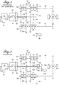
- figure 2 there is shown an embodiment of the invention, which is based on the transmission of the figure 1 .
- the references of the unchanged elements are not modified, and the corresponding but not identical elements have incremented references of the value 100.
- An additional gear has been placed on the second primary shaft 131, opposite the clutch 21. It is a fixed gear 182. It engraine with a pinion 181 fixedly mounted on the input shaft / output of the electrical machine 180, which has been moved relative to the transmission of the figure 1 .
- the input / output shaft is parallel to the primary and secondary trees.
- the primary shaft 131 is a little longer than figure 1 , but this is offset by the gains associated with the potential removal (or reduction in size) of the electric machine in the accessory facade.
- the second primary shaft 131 does not carry any other fixed gear, or at least does not carry a fixed gear for gear ratio engagement. It is inserted in a crazy shaft 132 which carries two idle gears 152 and 153 which engrain the pinions 63 and 65 for the first, and 61 for the second.
- a claw 133 makes it possible to couple the idler shaft 132 with the second shaft 131. It constitutes a means for coupling the clutched pair of sprockets 152, 65, and 153, 61 with the second input shaft 131 to engage the intermediate ratio 6 or 2. It couples an input pinion 153 of the pinion gear pairs 152, 65 and 153, 61, and the second input shaft 131.
- the pinions 182 and 181 constitute structure means for coupling the second input shaft 131 with the electric machine 180 opposite, with respect to the corresponding clutch 21, the heat engine 10, these structure means defining between the the heat engine 10 and the electric machine 180 a gear ratio of structure, independent of the gear ratio chosen at a given moment for driving the vehicle.
- the first primary shaft 30 rotates, by the pinions 51 and 60, the additional shaft 42 and the pinion 65.
- the pinion 65 rotates the pinion 152 and the crazy shaft 132, which by the pinions 153 and 61 rotates the pinion.
- second secondary shaft 41 The vehicle is propelled with the gear ratio 1 (T), and with a low speed.
- the second primary shaft 131 in rotation since the clutch 21 is closed, rotates the gears 182 and 181 and the electric machine 180, which is able to provide electricity for the electrical air conditioning or other consumers, embedded in the vehicle, strong electric power.
- the electric machine 15 may not be sized to provide a very large electrical power, since the electric machine 180 is usable in this situation.
- the implementation of the gear ratio 7 is shown: the elements in bold are again those which receive power from the engine.
- the clutch 20 is closed, and the clutch 21 is open.
- Synchronizers 70 and 71 have coupled gears 66 and 61 to the corresponding shafts.
- the clutch 133 is open: it constitutes a means for decoupling the clutched gear pairs 152, 65 and 153, 61 from the second input shaft 131 to decouple the electrical machine 180 from the first input shaft 30 while the high gear ratio 7 is engaged and that the electric machine 180 is not electrically powered.
- the first primary shaft 30 rotates, by the pinions 50 and 66, the additional shaft 42 and the pinion 65.
- the pinion 65 rotates the pinion 152 and the crazy shaft 132, which by the pinions 153 and 61 rotates the pinion.
- second secondary shaft 41 The vehicle is propelled with the gear ratio 7, and at a high speed.
- the electric machine 180 may not be powered, since the shaft 131 is not connected to the wheels of the vehicle.
- the electric machine 180 can be stopped.
Abstract
Système de transmission de puissance comprenant une boîte à rapport discrets et à deux arbres d'entrée, un moyen de structure pour coupler le deuxième arbre d'entrée (131) avec une machine électrique (180) à l'opposé du moteur thermique, ainsi qu'un premier et un deuxième couples de pignons, l'un des pignons de chaque couple étant monté fixe sur le premier arbre d'entrée (30) pour la propulsion avec des rapports de vitesses bas (T) et haut (7), un troisième couple de pignons, dont le pignon d'entrée est monté sur le deuxième arbre (131), pour la propulsion avec un rapport intermédiaire (2, 6), le pignon d'entrée (152, 153) du troisième couple étant monté fou sur le deuxième arbre (131), le système comprenant de plus un moyen de couplage du troisième couple de pignons avec le deuxième arbre pour engager le rapport intermédiaire, ou découpler la machine électrique du premier arbre (130).A power transmission system comprising a discrete ratio box and two input shafts, a structure means for coupling the second input shaft (131) with an electric machine (180) away from the heat engine, and a first and a second pair of gears, one of the gears of each pair being fixedly mounted on the first input shaft (30) for propulsion with low (T) and high (7) gears, a third pair of pinions, the input pinion of which is mounted on the second shaft (131), for propulsion with an intermediate ratio (2, 6), the input pinion (152, 153) of the third pair being mounted second system (131), the system further comprising means for coupling the third pair of gears with the second shaft to engage the intermediate gear, or decouple the electrical machine from the first shaft (130).
Description
L'invention s'inscrit dans le domaine des transmissions de puissance pour véhicule automobile hybride à propulsion basée sur un moteur thermique et une machine électrique, et impliquant une boîte de vitesses à rapports de vitesses discrets à laquelle est associée un embrayage permettant de passer les rapports alors que le moteur thermique est en fonctionnement.The invention is in the field of power transmissions for hybrid motor vehicle based on a heat engine and an electric machine, and involving a gearbox with discrete gear ratios which is associated with a clutch to pass the reports while the engine is running.
Plus précisément, on s'intéresse à une telle transmission dans laquelle la machine électrique capable de propulser le véhicule en situation d'arrêt ou de découplage du moteur thermique est placée en aval de l'embrayage. Il résulte de ce positionnement que la machine électrique est souvent entrainée ou freinée par les roues, l'embrayage n'étant pas utilisable pour la découpler de celles-ci. Si le véhicule roule vite, sans toutefois être propulsé par la machine électrique, celle-ci peut être entrainée en rotation et constituer un frein pour le véhicule, sauf à l'alimenter pour réduire son couple résistant. Si le véhicule roule lentement, la machine électrique peut être freinée, l'empêchant de pouvoir servir d'alternateur pour la production d'électricité, par exemple pour la climatisation de l'habitacle du véhicule, ou tout autre équipement gros consommateur de puissance électrique.More specifically, we are interested in such a transmission in which the electric machine capable of propelling the vehicle in a stopping or decoupling position of the engine is placed downstream of the clutch. It follows from this positioning that the electric machine is often driven or braked by the wheels, the clutch is not used to decouple them. If the vehicle rolls quickly, but not powered by the electric machine, it can be rotated and constitute a brake for the vehicle, except to feed it to reduce its resistant torque. If the vehicle is moving slowly, the electric machine can be braked, preventing it from being able to serve as an alternator for the production of electricity, for example for the air conditioning of the passenger compartment of the vehicle, or any other equipment consuming a large amount of electrical power. .
Ces difficultés apparaissent si la machine électrique est en prise avec l'arbre de sortie de la boîte de vitesses quand un rapport de vitesses bas, comme le premier rapport, ou un rapport de vitesses élevé, comme le septième rapport sur une boîte à 7 rapports, est engagé.These difficulties occur if the electric machine is engaged with the output shaft of the gearbox when a low gear ratio, such as the first gear, or a high gear ratio, such as the seventh gear on a 7-speed gearbox , is engaged.
Il est alors nécessaire, soit, dans la situation évoquée au cours de laquelle le véhicule roule lentement, d'utiliser une autre machine électrique, par exemple une machine électrique placée en façade accessoire du moteur thermique, pour alimenter la climatisation électrique, soit, dans la situation évoquée au cours de laquelle le véhicule roule vite, d'alimenter la machine électrique à l'aide d'une batterie pour réduire son couple résistant. Or la mise en place d'une machine électrique pour la climatisation a un coût conséquent, la puissance nécessaire étant importante. Cette considération est dimensionnante pour la machine électrique en façade accessoire. Quant à l'alimentation de la machine électrique pour réduire son couple résistant, il s'agit bien sûr d'une forme de gaspillage d'énergie.It is then necessary, either in the situation mentioned during which the vehicle is traveling slowly, to use another electric machine, for example an electric machine placed on the accessory front of the engine, to supply the electric air conditioning, or, in the evoked situation during which the vehicle rolls quickly, to power the electric machine with the help of a battery to reduce its resistant torque. Or the establishment of an electric machine for air conditioning has a cost, the necessary power is important. This consideration is dimensioning for the electric machine in accessory facade. As for the power supply of the electric machine to reduce its resistant torque, it is of course a form of waste of energy.
L'invention s'applique aux architectures dans lesquels au moins l'une ou l'autre de ces contraintes, liées à la cinématique interne de la boîte de vitesses est présente.The invention applies to architectures in which at least one or other of these constraints, related to the internal kinematics of the gearbox is present.
L'invention vise à résoudre les problèmes ci-dessus, de la manière la plus simple et la moins encombrante possible.The invention aims to solve the above problems in the simplest and least cumbersome way possible.
Pour cela il est proposé un système de transmission de puissance pour véhicule automobile à moteur thermique comprenant une boîte de vitesses à rapport de vitesses discrets et à deux arbres d'entrée, le système comprenant aussi un premier et un deuxième embrayages pour coupler ou découpler respectivement le premier et le deuxième des deux arbres d'entrée avec un moteur thermique du véhicule, la boîte comprenant des moyens de structure pour coupler le deuxième arbre d'entrée avec une machine électrique à l'opposé, par rapport à l'embrayage correspondant, du moteur thermique, les moyen de structure définissant entre le moteur thermique et la machine électrique un rapport de vitesses de structure, indépendant du rapport de vitesses choisi à un moment donné pour la conduite du véhicule, la boîte comprenant de plus
- un premier et un deuxième couples de pignons engrainés pour rapport de vitesses de marche avant, l'un des pignons de chaque couple étant monté fixe sur le premier arbre d'entrée,
- un premier système de couplage et commande pour coupler ou découpler le premier couple de pignons engrainés ou le deuxième couple de pignons engrainés avec un train de roues motrices du véhicule pour permettre la propulsion du véhicule à l'aide du moteur thermique et via le premier embrayage avec un rapport de vitesses bas et respectivement un rapport de vitesses haut,
- au moins un troisième couple de pignons engrainés pour rapport de vitesses de marche avant le pignon d'entrée du au moins un troisième couple étant monté sur le deuxième arbre d'entrée,
- et un deuxième système de couplage et commande pour coupler ou découpler le au moins un troisième couple de pignons engrainés avec le train de roues motrices du véhicule pour permettre la propulsion du véhicule à l'aide du moteur thermique et via le deuxième embrayage avec au moins un rapport de vitesses intermédiaire entre le rapport bas et le rapport haut,
- a first and a second pair of geared gears for gear ratio forward, one of the gears of each pair being fixedly mounted on the first input shaft,
- a first coupling and control system for coupling or decoupling the first pair of cogged gears or the second pair of cogged gears with a set of driving wheels of the vehicle to allow the propulsion of the vehicle with the aid of the engine and via the first clutch with a low gear ratio and a high gear ratio,
- at least a third pair of geared gears for gear ratio before the input gear of the at least one third pair being mounted on the second input shaft,
- and a second coupling and control system for coupling or decoupling the at least one third pair of geared gears with the drive train of the vehicle to allow the propulsion of the vehicle with the aid of the engine and via the second clutch with at least one gear ratio intermediate between the low gear and the high gear,
le premier système de couplage et commande mettant en oeuvre, à la fois pour le rapport bas et le rapport haut, une transmission de puissance impliquant la rotation du au moins un troisième couple de pignons engrainés à une vitesse proportionnelle à celle du premier arbre d'entrée, et le couplage du au moins un troisième couple de pignons engrainés avec le train de roues motrices du véhicule,the first coupling and control system implementing, for both the low gear and the high gear, a power transmission involving the rotation of the at least one third pair of geared gears at a speed proportional to that of the first gear shaft; input, and the coupling of the at least a third pair of geared gears with the drive train of the vehicle,
le pignon d'entrée du au moins un troisième couple de pignons engrainés étant monté fou sur le deuxième arbre d'entrée, le système comprend de plus un moyen de couplage et de découplage du au moins un troisième couple de pignons engrainés avec le deuxième arbre d'entrée pour
- engager le au moins un rapport intermédiaire,
- ou respectivement découpler la machine électrique du premier arbre d'entrée alors que
- a. le rapport de vitesses bas est engagé et que la machine électrique est couplée au moteur thermique par les moyen de structure,
- b. ou que le rapport de vitesses haut est engagé et que la machine électrique n'est pas alimentée électriquement.
- initiate at least one interim report,
- or respectively decouple the electrical machine from the first input shaft while
- at. the low gear ratio is engaged and that the electric machine is coupled to the engine by the structural means,
- b. or that the high gear ratio is engaged and that the electric machine is not electrically powered.
Ainsi, on a dissocié le régime de la machine électrique en prise sur le deuxième arbre primaire de celui des roues lorsque le rapport bas est engagé, ce qui permet de permettre à la machine électrique de tourner au régime du vilebrequin (à une démultiplication près), et de se comporter comme un alternateur bien que la vitesse du véhicule soit faible. Il est ainsi possible d'alimenter la climatisation avec la machine électrique actionnée par le moteur thermique.Thus, the speed of the electric machine has been dissociated in engagement with the second primary shaft of that of the wheels when the low gear is engaged, which makes it possible to allow the electric machine to rotate at crankshaft speed (at a gear ratio). , and to behave like an alternator although the speed of the vehicle is low. It is thus possible to supply the air conditioning with the electric machine operated by the engine.
La solution permet aussi, lorsque le rapport élevé est engagé de désynchroniser la machine électrique du régime des roues, et donc de ne pas puiser dans la batterie pour faire tourner la machine électrique au rythme des roues en sorte de supprimer son couple de freinage. Et si besoin est, il est possible, comme avec le rapport bas, de l'utiliser comme alternateur en la reliant au moteur.The solution also allows, when the high ratio is engaged to desynchronize the electric machine of the speed of the wheels, and therefore not to tap into the battery to rotate the electric machine to the rhythm of the wheels so as to remove its braking torque. And if necessary, it is possible, as with the low gear, to use it as an alternator by connecting it to the engine.
On peut donc supprimer l'alternateur existant sur la façade accessoire.We can therefore remove the existing alternator on the accessory facade.
L'invention peut aussi comprendre les caractéristiques suivantes, optionnelles et avantageuses :
- le moyen de couplage et de découplage du au moins un troisième couple de pignons engrainés avec le deuxième arbre d'entrée comprend un crabot couplant un pignon d'entrée du au moins un troisième couple de pignons engrainés et le deuxième arbre d'entrée,
- les moyens de structure pour coupler le deuxième arbre d'entrée avec une machine électrique à l'opposé, par rapport à l'embrayage correspondant, du moteur thermique comprennent un couple de pignons engrainés dont l'un est monté fixe sur le deuxième arbre d'entrée et l'autre sur l'arbre d'entrée de la machine électrique,
- le premier et le deuxième arbres d'entrée sont concentriques,
- le premier système de couplage et commande mobilise un pignon dit mixte qui est monté fou sur une première section d'un arbre de sortie de la boîte et fixe sur une deuxième section dudit arbre de sortie, les deux sections étant coaxiales, la première section étant couplée au premier arbre d'entrée quand le rapport bas ou le rapport haut est sélectionné, et la deuxième section étant couplée au deuxième arbre d'entrée quand le rapport de vitesses intermédiaire est sélectionné,
- le système comprend au moins deux troisièmes couples de pignons engrainés, les pignons d'entrée des au moins deux troisièmes couples de pignons engrainés étant chacun montés fixes sur un même arbre creux concentrique au deuxième arbre d'entrée,
- il comprend un système de couplage et commande pour coupler ou découpler le premier arbre d'entrée avec le train de roues motrices du véhicule, pour permettre la propulsion du véhicule avec un rapport ou deux rapports de vitesses intermédiaires supplémentaires entre le rapport bas et le rapport haut à l'aide du moteur thermique et via le premier embrayage,
- il comprend des moyens pour engager un rapport de marche arrière.
- the means for coupling and decoupling the at least one third pair of pinions engrained with the second input shaft comprises a dog coupling an input pinion of the at least a third pair of pinion gears and the second input shaft,
- the structure means for coupling the second input shaft with an electric machine opposite, with respect to the corresponding clutch, of the heat engine comprise a pair of sprocket gears, one of which is fixedly mounted on the second shaft; input and the other on the input shaft of the electric machine,
- the first and second input shafts are concentric,
- the first coupling and control system mobilizes a so-called mixed pinion which is mounted loosely on a first section of an output shaft of the box and fixed on a second section of said output shaft, the two sections being coaxial, the first section being coupled to the first input shaft when the low or high gear is selected, and the second section coupled to the second input shaft when the intermediate gear ratio is selected,
- the system comprises at least two third pairs of cogged gears, the input gears of the at least two third pairs of cogged gears being each fixedly mounted on the same concentric hollow shaft to the second input shaft,
- it comprises a coupling and control system for coupling or decoupling the first input shaft with the vehicle drive train, to allow propulsion of the vehicle with a ratio or two additional intermediate gears ratios between the low gear and the gear ratio. up using the heat engine and via the first clutch,
- it comprises means for engaging a reverse gear.
L'invention consiste aussi en un véhicule automobile à propulsion hybride comprenant un moteur thermique et une machine électrique pour sa propulsion, et un système de transmission selon l'invention, pour relier les roues motrices, la machine électrique et le moteur thermique.The invention also consists of a hybrid propulsion vehicle comprising a heat engine and an electric machine for its propulsion, and a transmission system according to the invention for connecting the driving wheels, the electric machine and the heat engine.
L'invention sera mieux comprise, et d'autres buts, caractéristiques, détails et avantages de celle-ci apparaîtront plus clairement dans la description explicative qui va suivre faite en référence aux dessins annexés donnés uniquement à titre d'exemple illustrant un mode de réalisation de l'invention et dans lesquels :
- La
figure 1 est une représentation d'une transmission sur laquelle est basée l'invention ; - la
figure 2 est une vue d'un mode de réalisation de l'invention ; - la
figure 3 est une vue d'un mode de mise en oeuvre de la transmission de lafigure 2 ; - la
figure 4 est une d'un autre mode de mise en oeuvre de la transmission de lafigure 2 .
- The
figure 1 is a representation of a transmission on which the invention is based; - the
figure 2 is a view of an embodiment of the invention; - the
figure 3 is a view of a mode of implementation of the transmission of thefigure 2 ; - the
figure 4 is one of another mode of implementation of the transmission of thefigure 2 .
En
L'ensemble comprend un moteur thermique 10, lié à un premier et un deuxième embrayages de sortie 20 et 21. Les embrayages 20 et 21 couplent le moteur thermique 10 à respectivement un premier et un deuxième arbres primaires 30 et 31 (ou arbres d'entrée), parallèles concentriques. Le deuxième arbre primaire 31 est placé à l'intérieur du premier arbre primaire 30, qui est creux.The assembly comprises a
Le moteur thermique 10 porte, en face accessoire, une machine électrique 15 qu'il peut actionner pour produire de l'électricité. Un démarreur (non référencé) est également présent, pour faciliter le démarrage du moteur thermique 10.The
La boîte de vitesses comporte un premier et un deuxième arbres secondaires 40 et 41 (ou arbres de sortie), parallèles entre eux et parallèles aux arbres primaires.The gearbox has first and second
Le premier arbre primaire 30 porte deux pignons fixes 50 et 51. Le deuxième arbre primaire 31 porte deux autres pignons fixes 52 et 53.The first
Les pignons fixes 50, 51 et 52 engrainent respectivement chacun deux pignons de sortie de rapport de marche avant. Ces paires de pignons de sortie sont référencés 64 et 66, 60 et 62, et enfin 65 et 63. Le pignon fixe 53 engraine un pignon de sortie de rapport de marche avant. Ce pignon de sortie est référencé 61.The fixed gears 50, 51 and 52 respectively engrain respectively two forward gear output gears. These pairs of output gears are referenced 64 and 66, 60 and 62, and finally 65 and 63. The fixed
Les pignons 64, 62 et 63 sont des pignons fous portés par le premier arbre secondaire 40. Les pignons 65 et 61 sont des pignons fous portés par le deuxième arbre secondaire 41. Le pignon 65 est aussi un pignon fixe monté sur un arbre supplémentaire 42 parallèle concentrique au deuxième arbre secondaire 41, dans le prolongement de celui-ci. Les pignons 66 et 60 sont montés fous sur cet arbre supplémentaire 42. Un pignon de marche arrière 67 est aussi monté sur le premier arbre secondaire 40.The
Le deuxième arbre secondaire 41 et l'arbre supplémentaire 42 constituent deux sections d'un arbre de sortie de la boîte de vitesses. Le pignon 65 est dit mixte.The second
Les pignons s'organisent en couples de pignons engrainés pour les rapports de vitesses de marche avant. Les pignons 50, 51 et 52 participent à deux couples. De rapport le plus bas au rapport le plus élevé, les couples de pignons sont 51, 60 - 53, 61 - 51, 62 - 53, 63 - 50, 64 - 52, 65 - 50, 66. L'ensemble définit quatre plans de pignons.The gears are organized in pairs of sprockets for gear ratios forward. The
Des synchroniseurs 70, 71, 72 et 73 permettent de solidariser respectivement les pignons 66 ou 60, 65 ou 61, 64 ou 62, et 63 ou 67 aux arbres sur lesquels ces pignons sont montés fous. Chaque synchroniseur solidarise avec l'arbre correspondant un des deux pignons dont il a la charge tout en désolidarisant nécessairement l'autre des deux pignons. Chaque synchroniseur peut aussi ne solidariser ni l'un ni l'autre des deux pignons dont il a la charge.
Dans cette architecture, la mise en oeuvre du synchroniseur 70 pour solidariser le pignon 66 ou le pignon 60 avec l'arbre supplémentaire 42 implique nécessairement la mise en oeuvre du synchroniseur 71 pour solidariser le pignon 61 avec le deuxième arbre secondaire 61. Un système de commande (non représenté) met en oeuvre ce mouvement imposé.In this architecture, the implementation of the
Les deux arbres secondaires 40 et 41 sont reliés au train de roues motrices 90 du véhicule, comprenant un différentiel.The two
Une machine électrique 80 est présente et possède un arbre d'entrée/sortie parallèle aux arbres primaires et secondaires et qui dispose d'un pignon fixe 81 qui engraine avec le pignon 61 et donc le pignon 53 et l'arbre 31.An
Les rapports 1 (T), 2, 3, 4, 5, 6, 7 et R sont mis en oeuvre par couplage aux arbres correspondants des pignons respectivement 60, 61, 62, 63, 64, 65, 66 et 67.The ratios 1 (T), 2, 3, 4, 5, 6, 7 and R are implemented by coupling to the corresponding shafts of the gears respectively 60, 61, 62, 63, 64, 65, 66 and 67.
Le synchroniseur 70 et l'arbre supplémentaire 42 constituent ensemble, avec le système de commande (non représenté) mettant en oeuvre le mouvement imposé du synchroniseur 71 mentionné plus haut, un système de couplage et commande permettant le couplage ou le découplage des rapports de vitesses 1(T) ou 7, via les couples de pignons engrainés 50, 66 ou 51, 60, pour permettre la propulsion du véhicule à l'aide du moteur thermique et via le premier embrayage 20.The
Les pignons 53, 61 et 81 constituent des moyens de structure pour coupler le deuxième arbre d'entrée 31 avec la machine électrique 80 à l'opposé, par rapport à l'embrayage correspondant 21, du moteur thermique 10, ces moyens de structure définissant entre le moteur thermique 10 et la machine électrique 80 un rapport de vitesses de structure, indépendant du rapport de vitesses choisi à un moment donné pour la conduite du véhicule.The
Les rapports T et 7 étant des rapports bas et haut, les rapports 2 et 6 sont des rapports intermédiaires, ainsi que les rapports 3, 5 et 4, ces derniers étant, dans le contexte de l'invention, des rapports intermédiaires supplémentaires.The ratios T and 7 being low and high ratios, the
En
Un pignon supplémentaire a été placé sur le deuxième arbre primaire 131, à l'opposé de l'embrayage 21. Il s'agit d'un pignon fixe 182. Il engraine avec un pignon 181 monté fixe sur l'arbre d'entrée/sortie de la machine électrique 180, qui a été déplacée par rapport à la transmission de la
Le deuxième arbre primaire 131 ne porte pas d'autre pignon fixe, ou du moins ne porte pas de pignon fixe pour l'engagement de rapport de vitesses. Il est inséré dans un arbre fou 132 qui porte deux pignons fous 152 et 153 qui engrainent les pignons 63 et 65 pour le premier, et 61 pour le deuxième.The second
Un crabot 133 permet de coupler l'arbre fou 132 avec le deuxième arbre 131. Il constitue un moyen de couplage des couple de pignons engrainés 152, 65, et 153, 61 avec le deuxième arbre d'entrée 131 pour engager le rapport intermédiaire 6 ou 2. Il couple un pignon d'entrée 153 des couples de pignons engrainés 152, 65 et 153, 61, et le deuxième arbre d'entrée 131.A
Les pignons 182 et 181 constituent des moyens de structure pour coupler le deuxième arbre d'entrée 131 avec la machine électrique 180 à l'opposé, par rapport à l'embrayage correspondant 21, du moteur thermique 10, ces moyens de structure définissant entre le moteur thermique 10 et la machine électrique 180 un rapport de vitesses de structure, indépendant du rapport de vitesses choisi à un moment donné pour la conduite du véhicule.The
En
Le premier arbre primaire 30 fait tourner, par les pignons 51 et 60, l'arbre supplémentaire 42 et le pignon 65. Le pignon 65 fait tourner le pignon 152 et l'arbre fou 132, qui par les pignons 153 et 61 fait tourner le deuxième arbre secondaire 41. Le véhicule est propulsé avec le rapport de vitesses 1 (T), et avec une vitesse faible.The first
Le deuxième arbre primaire 131, en rotation puisque l'embrayage 21 est fermé, fait tourner les pignons 182 et 181 et la machine électrique 180, qui est en mesure de fournir de l'électricité pour la climatisation électrique ou d'autres consommateurs, embarqués dans le véhicule, de fortes puissances électriques.The second
La machine électrique 15 peut ne pas être dimensionnée pour fournir une puissance électrique très importante, puisque la machine électrique 180 est utilisable dans cette situation.The
En
Le premier arbre primaire 30 fait tourner, par les pignons 50 et 66, l'arbre supplémentaire 42 et le pignon 65. Le pignon 65 fait tourner le pignon 152 et l'arbre fou 132, qui par les pignons 153 et 61 fait tourner le deuxième arbre secondaire 41. Le véhicule est propulsé avec le rapport de vitesses 7, et à une vitesse élevée.The first
La machine électrique 180 peut ne pas être alimentée, puisque l'arbre 131 n'est pas relié aux roues du véhicule. La machine électrique 180 peut être arrêtée.The
Claims (9)
caractérisé en ce que le pignon d'entrée (152, 153) du au moins un troisième couple de pignons engrainés (152, 65, 153, 61) est monté fou sur le deuxième arbre d'entrée (131), le système comprenant de plus un moyen de couplage et de découplage (133) du au moins un troisième couple de pignons engrainés (152, 65, 153, 61) avec le deuxième arbre d'entrée (131) pour engager le au moins un rapport intermédiaire, ou respectivement découpler la machine électrique (180) du premier arbre d'entrée (30) alors que le rapport de vitesses bas (T) est engagé et que la machine électrique (180) est couplée au moteur thermique (10) par les moyens de structure (181, 182) ou que le rapport de vitesses haut (7) est engagé et que la machine électrique (180) n'est pas alimentée électriquement.A power transmission system for a motor vehicle with a heat engine (10), comprising a gearbox with discrete gear ratio and two input shafts (30, 131), the system also comprising a first and a second clutch (20). , 21) for respectively coupling or decoupling the first and second of the two input shafts (30, 131) with a heat engine (10) of the vehicle, the box comprising structure means for coupling (181, 182) the second input shaft (131) with an electric machine (180) opposite, with respect to the corresponding clutch (21), the heat engine (10), the coupling structure means (181, 182) defining between the heat engine (10) and the electric machine (180) have a gear ratio that is independent of the gear ratio chosen at a given moment for driving the vehicle, the gearbox further comprising
characterized in that the input gear (152, 153) of the at least one third pair of cogged gears (152, 65, 153, 61) is idly mounted on the second input shaft (131), the system comprising plus means for coupling and decoupling (133) of the at least one third pair of cogged gears (152, 65, 153, 61) with the second input shaft (131) to engage the at least one intermediate gear, or respectively decoupling the electric machine (180) from the first input shaft (30) while the low gear ratio (T) is engaged and the electric machine (180) is coupled to the engine (10) by the structural means ( 181, 182) or that the high gear ratio (7) is engaged and that the electric machine (180) is not powered electrically.
Applications Claiming Priority (1)
| Application Number | Priority Date | Filing Date | Title |
|---|---|---|---|
| FR1658728A FR3056157B1 (en) | 2016-09-19 | 2016-09-19 | POWER TRANSMISSION SYSTEM FOR MOTOR VEHICLE |
Publications (1)
| Publication Number | Publication Date |
|---|---|
| EP3296592A1 true EP3296592A1 (en) | 2018-03-21 |
Family
ID=57485677
Family Applications (1)
| Application Number | Title | Priority Date | Filing Date |
|---|---|---|---|
| EP17186800.3A Withdrawn EP3296592A1 (en) | 2016-09-19 | 2017-08-18 | Power transmission system for motor vehicle and motor vehicle |
Country Status (2)
| Country | Link |
|---|---|
| EP (1) | EP3296592A1 (en) |
| FR (1) | FR3056157B1 (en) |
Cited By (1)
| Publication number | Priority date | Publication date | Assignee | Title |
|---|---|---|---|---|
| US20220396144A1 (en) * | 2021-06-10 | 2022-12-15 | Volvo Truck Corporation | Transmission, A Powertrain, And A Vehicle |
Citations (5)
| Publication number | Priority date | Publication date | Assignee | Title |
|---|---|---|---|---|
| WO2006040150A1 (en) * | 2004-10-16 | 2006-04-20 | Daimlerchrysler Ag | Transmission set and hybrid double-clutch transmission |
| FR2881381A1 (en) | 2005-02-02 | 2006-08-04 | Volkswagen Ag | Drive for motor vehicle, has electric machine installed between internal combustion engine and twin-clutch manual transmission and connected to combustion engine by utilizing additional clutch |
| DE102005049992A1 (en) * | 2005-10-12 | 2007-04-26 | Getrag Getriebe- Und Zahnradfabrik Hermann Hagenmeyer Gmbh & Cie Kg | Drive train for a cross country four-wheel drive vehicle, with a twin-clutch gearbox, has electric machines at both part-drives acting as generators or motors |
| EP2216193A1 (en) * | 2009-02-09 | 2010-08-11 | FERRARI S.p.A. | Road vehicle with hybrid propulsion |
| JP2013019439A (en) * | 2011-07-08 | 2013-01-31 | Mitsubishi Motors Corp | Transmission |
-
2016
- 2016-09-19 FR FR1658728A patent/FR3056157B1/en active Active
-
2017
- 2017-08-18 EP EP17186800.3A patent/EP3296592A1/en not_active Withdrawn
Patent Citations (5)
| Publication number | Priority date | Publication date | Assignee | Title |
|---|---|---|---|---|
| WO2006040150A1 (en) * | 2004-10-16 | 2006-04-20 | Daimlerchrysler Ag | Transmission set and hybrid double-clutch transmission |
| FR2881381A1 (en) | 2005-02-02 | 2006-08-04 | Volkswagen Ag | Drive for motor vehicle, has electric machine installed between internal combustion engine and twin-clutch manual transmission and connected to combustion engine by utilizing additional clutch |
| DE102005049992A1 (en) * | 2005-10-12 | 2007-04-26 | Getrag Getriebe- Und Zahnradfabrik Hermann Hagenmeyer Gmbh & Cie Kg | Drive train for a cross country four-wheel drive vehicle, with a twin-clutch gearbox, has electric machines at both part-drives acting as generators or motors |
| EP2216193A1 (en) * | 2009-02-09 | 2010-08-11 | FERRARI S.p.A. | Road vehicle with hybrid propulsion |
| JP2013019439A (en) * | 2011-07-08 | 2013-01-31 | Mitsubishi Motors Corp | Transmission |
Cited By (2)
| Publication number | Priority date | Publication date | Assignee | Title |
|---|---|---|---|---|
| US20220396144A1 (en) * | 2021-06-10 | 2022-12-15 | Volvo Truck Corporation | Transmission, A Powertrain, And A Vehicle |
| US11794574B2 (en) * | 2021-06-10 | 2023-10-24 | Volvo Truck Corporation | Transmission, a powertrain, and a vehicle |
Also Published As
| Publication number | Publication date |
|---|---|
| FR3056157B1 (en) | 2018-10-26 |
| FR3056157A1 (en) | 2018-03-23 |
Similar Documents
| Publication | Publication Date | Title |
|---|---|---|
| EP2694309B1 (en) | Hybrid transmission for a motor vehicle, and control method | |
| EP3013618B1 (en) | Hybrid transmission with an additional electric machine | |
| EP1042135B1 (en) | Transmission device for motor vehicle with hybrid propulsion comprising a drive coupling for the electric engine | |
| FR2959174A1 (en) | VEHICLE WITH ELECTRICAL DRIVE | |
| EP1013494A2 (en) | Parallel hybrid drive for motor vehicle | |
| EP3055159A1 (en) | Motor vehicle powertrain and method of operation | |
| FR2928583A1 (en) | Transmission for electric machine to drive hybrid vehicle, has two step-down ratios engaged by actuator and by axial sliding of jaw clutch sleeve, and dead center integrating electric machine with wheels of hybrid vehicle | |
| FR2946293A1 (en) | Drive train for electric vehicle, has speed changing mechanism comprising main shaft for holding idler gears, secondary shaft for holding fixed pinions and middle reduction shaft arranged between secondary shaft and ring gear of vehicle | |
| EP3296592A1 (en) | Power transmission system for motor vehicle and motor vehicle | |
| EP1801455B1 (en) | Manual or automated powershift transmission with three parallel shafts | |
| WO2010007291A1 (en) | Hybrid gearbox with parallel shafts | |
| FR3060476A1 (en) | POWER TRANSMISSION SYSTEM FOR MOTOR VEHICLE | |
| WO2011055050A1 (en) | Multiple-ratio hybrid power train having two electrical machines | |
| WO2017068256A1 (en) | Hybrid transmission for a motor vehicle | |
| WO2021094532A1 (en) | Compact powertrain comprising two electric motors and one combustion engine which are not coaxial, and method for controlling same | |
| FR2946292A3 (en) | Power train for motor vehicle, has electrical machine for driving wheels of motor vehicle by speed changing mechanism, and input clutches intercalated between electrical machine and speed changing mechanism | |
| FR3031478A1 (en) | GEARBOX FOR MOTOR VEHICLE | |
| FR2951237A1 (en) | Robotic transmission e.g. torque branching transmission, for e.g. hybrid four drive wheel vehicle, has primary shaft rotatably connected to fly-wheel of engine in permanent manner, where counter shaft is connected to fly-wheel via clutch | |
| FR3098766A1 (en) | Automatic transmission for thermal / electric hybrid vehicle | |
| WO2021170523A1 (en) | Motorised module, hybrid sub-assembly for driving a vehicle, and method for engaging a pawl in the hybrid sub-assembly | |
| WO2015128558A1 (en) | Automatic transmission for combustion or hybrid powered motor vehicle | |
| EP4094963A1 (en) | Hybrid subassembly for driving a vehicle, hybrid engine unit and hybrid driving method | |
| FR3135423A1 (en) | MODULAR ELECTRIC TRAIN FOR MOTOR VEHICLE | |
| FR2939485A1 (en) | GEARBOX WITH AUXILIARY SHAFT OF FIRST AND REVERSE. | |
| FR3107014A1 (en) | HYBRID MOTOR VEHICLE TRANSMISSION CONSISTING OF TWO ELECTRIC MACHINES AND AT LEAST THREE GEARS |
Legal Events
| Date | Code | Title | Description |
|---|---|---|---|
| PUAI | Public reference made under article 153(3) epc to a published international application that has entered the european phase |
Free format text: ORIGINAL CODE: 0009012 |
|
| STAA | Information on the status of an ep patent application or granted ep patent |
Free format text: STATUS: THE APPLICATION HAS BEEN PUBLISHED |
|
| AK | Designated contracting states |
Kind code of ref document: A1 Designated state(s): AL AT BE BG CH CY CZ DE DK EE ES FI FR GB GR HR HU IE IS IT LI LT LU LV MC MK MT NL NO PL PT RO RS SE SI SK SM TR |
|
| AX | Request for extension of the european patent |
Extension state: BA ME |
|
| STAA | Information on the status of an ep patent application or granted ep patent |
Free format text: STATUS: REQUEST FOR EXAMINATION WAS MADE |
|
| 17P | Request for examination filed |
Effective date: 20180831 |
|
| RBV | Designated contracting states (corrected) |
Designated state(s): AL AT BE BG CH CY CZ DE DK EE ES FI FR GB GR HR HU IE IS IT LI LT LU LV MC MK MT NL NO PL PT RO RS SE SI SK SM TR |
|
| RIC1 | Information provided on ipc code assigned before grant |
Ipc: F16H 3/093 20060101ALI20171211BHEP Ipc: F16H 3/08 20060101ALN20171211BHEP Ipc: B60K 6/48 20071001ALI20171211BHEP Ipc: F16H 3/00 20060101AFI20171211BHEP Ipc: B60K 6/547 20071001ALI20171211BHEP |
|
| RAP1 | Party data changed (applicant data changed or rights of an application transferred) |
Owner name: PSA AUTOMOBILES SA |
|
| STAA | Information on the status of an ep patent application or granted ep patent |
Free format text: STATUS: EXAMINATION IS IN PROGRESS |
|
| 17Q | First examination report despatched |
Effective date: 20210325 |
|
| STAA | Information on the status of an ep patent application or granted ep patent |
Free format text: STATUS: THE APPLICATION IS DEEMED TO BE WITHDRAWN |
|
| 18D | Application deemed to be withdrawn |
Effective date: 20210805 |