EP3296580B1 - Electrical isolation of angle of attack vane bearings - Google Patents
Electrical isolation of angle of attack vane bearings Download PDFInfo
- Publication number
- EP3296580B1 EP3296580B1 EP17191546.5A EP17191546A EP3296580B1 EP 3296580 B1 EP3296580 B1 EP 3296580B1 EP 17191546 A EP17191546 A EP 17191546A EP 3296580 B1 EP3296580 B1 EP 3296580B1
- Authority
- EP
- European Patent Office
- Prior art keywords
- bearing
- shaft
- mounting flange
- inner race
- outer race
- Prior art date
- Legal status (The legal status is an assumption and is not a legal conclusion. Google has not performed a legal analysis and makes no representation as to the accuracy of the status listed.)
- Active
Links
- 238000002955 isolation Methods 0.000 title 1
- 239000000919 ceramic Substances 0.000 claims description 21
- 239000003989 dielectric material Substances 0.000 claims description 14
- 238000000034 method Methods 0.000 claims description 9
- 238000005096 rolling process Methods 0.000 claims description 8
- 239000002131 composite material Substances 0.000 claims description 7
- 230000004888 barrier function Effects 0.000 description 61
- 238000009760 electrical discharge machining Methods 0.000 description 12
- 238000005259 measurement Methods 0.000 description 9
- 238000006073 displacement reaction Methods 0.000 description 5
- 239000004020 conductor Substances 0.000 description 4
- 230000000694 effects Effects 0.000 description 3
- 239000012530 fluid Substances 0.000 description 3
- 238000005524 ceramic coating Methods 0.000 description 2
- 238000009413 insulation Methods 0.000 description 2
- 239000000463 material Substances 0.000 description 2
- 229910001092 metal group alloy Inorganic materials 0.000 description 2
- 230000037361 pathway Effects 0.000 description 2
- 238000013459 approach Methods 0.000 description 1
- 229910010293 ceramic material Inorganic materials 0.000 description 1
- 238000001816 cooling Methods 0.000 description 1
- 238000013016 damping Methods 0.000 description 1
- 238000002844 melting Methods 0.000 description 1
- 230000008018 melting Effects 0.000 description 1
- 239000002184 metal Substances 0.000 description 1
- 239000012811 non-conductive material Substances 0.000 description 1
- 230000010355 oscillation Effects 0.000 description 1
- 230000002028 premature Effects 0.000 description 1
Images


Classifications
-
- B—PERFORMING OPERATIONS; TRANSPORTING
- B64—AIRCRAFT; AVIATION; COSMONAUTICS
- B64D—EQUIPMENT FOR FITTING IN OR TO AIRCRAFT; FLIGHT SUITS; PARACHUTES; ARRANGEMENT OR MOUNTING OF POWER PLANTS OR PROPULSION TRANSMISSIONS IN AIRCRAFT
- B64D45/00—Aircraft indicators or protectors not otherwise provided for
- B64D45/02—Lightning protectors; Static dischargers
-
- B—PERFORMING OPERATIONS; TRANSPORTING
- B64—AIRCRAFT; AVIATION; COSMONAUTICS
- B64D—EQUIPMENT FOR FITTING IN OR TO AIRCRAFT; FLIGHT SUITS; PARACHUTES; ARRANGEMENT OR MOUNTING OF POWER PLANTS OR PROPULSION TRANSMISSIONS IN AIRCRAFT
- B64D43/00—Arrangements or adaptations of instruments
-
- B—PERFORMING OPERATIONS; TRANSPORTING
- B64—AIRCRAFT; AVIATION; COSMONAUTICS
- B64D—EQUIPMENT FOR FITTING IN OR TO AIRCRAFT; FLIGHT SUITS; PARACHUTES; ARRANGEMENT OR MOUNTING OF POWER PLANTS OR PROPULSION TRANSMISSIONS IN AIRCRAFT
- B64D43/00—Arrangements or adaptations of instruments
- B64D43/02—Arrangements or adaptations of instruments for indicating aircraft speed or stalling conditions
-
- F—MECHANICAL ENGINEERING; LIGHTING; HEATING; WEAPONS; BLASTING
- F16—ENGINEERING ELEMENTS AND UNITS; GENERAL MEASURES FOR PRODUCING AND MAINTAINING EFFECTIVE FUNCTIONING OF MACHINES OR INSTALLATIONS; THERMAL INSULATION IN GENERAL
- F16C—SHAFTS; FLEXIBLE SHAFTS; ELEMENTS OR CRANKSHAFT MECHANISMS; ROTARY BODIES OTHER THAN GEARING ELEMENTS; BEARINGS
- F16C11/00—Pivots; Pivotal connections
- F16C11/04—Pivotal connections
-
- F—MECHANICAL ENGINEERING; LIGHTING; HEATING; WEAPONS; BLASTING
- F16—ENGINEERING ELEMENTS AND UNITS; GENERAL MEASURES FOR PRODUCING AND MAINTAINING EFFECTIVE FUNCTIONING OF MACHINES OR INSTALLATIONS; THERMAL INSULATION IN GENERAL
- F16C—SHAFTS; FLEXIBLE SHAFTS; ELEMENTS OR CRANKSHAFT MECHANISMS; ROTARY BODIES OTHER THAN GEARING ELEMENTS; BEARINGS
- F16C33/00—Parts of bearings; Special methods for making bearings or parts thereof
- F16C33/30—Parts of ball or roller bearings
- F16C33/303—Parts of ball or roller bearings of hybrid bearings, e.g. rolling bearings with steel races and ceramic rolling elements
-
- G—PHYSICS
- G01—MEASURING; TESTING
- G01P—MEASURING LINEAR OR ANGULAR SPEED, ACCELERATION, DECELERATION, OR SHOCK; INDICATING PRESENCE, ABSENCE, OR DIRECTION, OF MOVEMENT
- G01P13/00—Indicating or recording presence, absence, or direction, of movement
- G01P13/02—Indicating direction only, e.g. by weather vane
- G01P13/025—Indicating direction only, e.g. by weather vane indicating air data, i.e. flight variables of an aircraft, e.g. angle of attack, side slip, shear, yaw
-
- F—MECHANICAL ENGINEERING; LIGHTING; HEATING; WEAPONS; BLASTING
- F16—ENGINEERING ELEMENTS AND UNITS; GENERAL MEASURES FOR PRODUCING AND MAINTAINING EFFECTIVE FUNCTIONING OF MACHINES OR INSTALLATIONS; THERMAL INSULATION IN GENERAL
- F16C—SHAFTS; FLEXIBLE SHAFTS; ELEMENTS OR CRANKSHAFT MECHANISMS; ROTARY BODIES OTHER THAN GEARING ELEMENTS; BEARINGS
- F16C19/00—Bearings with rolling contact, for exclusively rotary movement
- F16C19/02—Bearings with rolling contact, for exclusively rotary movement with bearing balls essentially of the same size in one or more circular rows
- F16C19/14—Bearings with rolling contact, for exclusively rotary movement with bearing balls essentially of the same size in one or more circular rows for both radial and axial load
- F16C19/16—Bearings with rolling contact, for exclusively rotary movement with bearing balls essentially of the same size in one or more circular rows for both radial and axial load with a single row of balls
-
- F—MECHANICAL ENGINEERING; LIGHTING; HEATING; WEAPONS; BLASTING
- F16—ENGINEERING ELEMENTS AND UNITS; GENERAL MEASURES FOR PRODUCING AND MAINTAINING EFFECTIVE FUNCTIONING OF MACHINES OR INSTALLATIONS; THERMAL INSULATION IN GENERAL
- F16C—SHAFTS; FLEXIBLE SHAFTS; ELEMENTS OR CRANKSHAFT MECHANISMS; ROTARY BODIES OTHER THAN GEARING ELEMENTS; BEARINGS
- F16C2202/00—Solid materials defined by their properties
- F16C2202/30—Electric properties; Magnetic properties
- F16C2202/32—Conductivity
-
- F—MECHANICAL ENGINEERING; LIGHTING; HEATING; WEAPONS; BLASTING
- F16—ENGINEERING ELEMENTS AND UNITS; GENERAL MEASURES FOR PRODUCING AND MAINTAINING EFFECTIVE FUNCTIONING OF MACHINES OR INSTALLATIONS; THERMAL INSULATION IN GENERAL
- F16C—SHAFTS; FLEXIBLE SHAFTS; ELEMENTS OR CRANKSHAFT MECHANISMS; ROTARY BODIES OTHER THAN GEARING ELEMENTS; BEARINGS
- F16C2206/00—Materials with ceramics, cermets, hard carbon or similar non-metallic hard materials as main constituents
- F16C2206/40—Ceramics, e.g. carbides, nitrides, oxides, borides of a metal
-
- F—MECHANICAL ENGINEERING; LIGHTING; HEATING; WEAPONS; BLASTING
- F16—ENGINEERING ELEMENTS AND UNITS; GENERAL MEASURES FOR PRODUCING AND MAINTAINING EFFECTIVE FUNCTIONING OF MACHINES OR INSTALLATIONS; THERMAL INSULATION IN GENERAL
- F16C—SHAFTS; FLEXIBLE SHAFTS; ELEMENTS OR CRANKSHAFT MECHANISMS; ROTARY BODIES OTHER THAN GEARING ELEMENTS; BEARINGS
- F16C2326/00—Articles relating to transporting
- F16C2326/43—Aeroplanes; Helicopters
Definitions
- the present disclosure relates generally to electrically isolating angle of attack vanes. More particularly, this disclosure relates to electrically isolating the bearings of angle of attack vanes.
- Angular measurement devices such as angle of attack (AOA) and side slip angle (SSA) vanes, project from an aircraft body and are free to rotate and align with the prevailing airflow.
- the angular measurement vane rotates with the prevailing airflow and provides such rotational information to electronics within the aircraft.
- the trajectory of the aircraft and the degree of rotation of the angular measurement vane is used to calculate the angle of attack or the side slip angle of the aircraft, and such information is provided to the cockpit and to relevant systems on the aircraft.
- Angular measurement vanes project outside of the aircraft and into the prevailing airflow.
- a shaft extends into the aircraft body from the angular measurement vane and into an electronics enclosure, where electronics measure the rotational displacement of the shaft.
- Bearings rotatably support the shaft relative to mounting hardware, which mounting hardware is secured to the body of the aircraft. The shaft is thus free to rotate relative to the mounting hardware such that the angular measurement vane is free to rotate with the prevailing airflow.
- the angular measurement vane, shaft, bearings, and mounting hardware are typically metallic, and the vane and mounting hardware are exposed to the environment, and as such, are particularly susceptible to lightning strikes.
- the electrical current from a lightning strike on the vane, mounting hardware, or other locations on the aircraft body can pass through the bearings of the angular measurement vane.
- the large electrical current generated by a lightning strike which can exceed 130 kilovolts, arcs through the bearings of the angular measurement vane and can cause fluting damage, which can lead to rough or stiff bearing failures.
- an angle of attack vane mounting system includes a mounting flange secured to an aircraft, a shaft extending through the mounting flange, a bearing disposed between the mounting flange and the shaft, and an electric isolator.
- the bearing includes an inner race attached to the shaft and an outer race attached to the mounting flange.
- the electric isolator is disposed adjacent one of the inner race and the outer race and electrically isolates the bearing such that an electric current is prevented from passing between the inner race and the outer race.
- Such electrically isolating bearings in itself are known for example from US2001048781 .
- an angle of attack vane for an aircraft includes an outboard mounting flange, an inboard mounting flange disposed adjacent the outboard mounting flange, a shaft extending through the outboard mounting flange and the inboard mounting flange, an inboard bearing rotatably supporting the shaft and disposed between the shaft and the inboard mounting flange, an inboard electric isolator configured to prevent an electric current from traveling through the inboard bearing, an outboard bearing rotatably supporting the shaft and disposed between the outboard mounting flange and the shaft, an outboard electric isolator configured to prevent an electric current from traveling through the outboard bearing, and a vane extending from the shaft outboard of the outboard mounting flange.
- a method of preventing lightning strike damage to a bearing of an angle of attack vane includes mounting an angle of attack vane shaft on a bearing disposed between the angle of attack vane shaft and a mounting flange and electrically isolating the bearing such that an electrical current cannot pass between an inner race of the bearing and an outer race of the bearing.
- FIG. 1 is a perspective view of aircraft 10.
- Aircraft 10 includes fuselage 12, wings 14, and engines 16.
- Fuselage 12 includes angle of attack (AOA) vane 18.
- AOA vane 18 projects from fuselage 12 forward of wings 14.
- AOA vane 18 rotates to align with the prevailing airflow.
- AOA vane 18 is preferably located forward of wings 14. Locating AOA vane 18 forward of wings 14 minimizes the effects on AOA vane 18 of the airflow affected by fuselage 12, wings 14, or engines 16, thereby ensuring the accuracy of AOA vane 18. For example, as aircraft 10 ascends, AOA vane 18 aligns with the prevailing airflow and indicates a high angle of attack. As aircraft 10 approaches a cruise altitude AOA vane 18 continues to track with the prevailing airflow, and AOA vane 18 thus indicates a lower angle of attack as aircraft 10 levels off. Because AOA vane 18 projects from fuselage 12, AOA vane 18 is exposed to the elements and is particularly susceptible to lighting strikes.
- AOA vane 18 When lightning strikes AOA vane 18 the electrical current generated by the lightning strike travels through AOA vane 18 and seeks a low-impedance path to fuselage 12. While AOA vane 18 is described as measuring the angle of attack, it is understood that AOA vane 18 may be any angular sensing instrument, such as an AOA vane or a side slip angle vane.
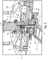
- FIG. 2 is a cross-sectional view of AOA vane 18, mounting system 20, and electric isolator 22.
- AOA vane 18 includes vane body 24 and shaft 26.
- Mounting system 20 includes outboard mounting flange 28, inboard mounting flange 30, outboard bearing 32, and inboard bearing 34.
- Mounting system 20 further includes rotary position sensor 36 and damper 38.
- Outboard bearing 32 includes outer race 40a, inner race 42a, and ball 44a.
- Inboard bearing 34 outer race 40b, inner race 42b, and ball 44b.
- Electric isolator 22 may include dielectric barrier 46a, dielectric barrier 46b, dielectric barrier 46c, and dielectric barrier 46d.
- Mounting system 20 is attached to fuselage 12 (shown in FIG. 1 ) and supports AOA vane 18.
- Outboard mounting flange 28 is disposed outward of and secured to inboard mounting flange 30.
- Shaft 26 extends through outboard mounting flange 28 and inboard mounting flange 30 and communicates with rotary position sensor 36.
- Rotary position sensor 36 is inboard of shaft 26 and is configured to sense a rotational displacement of shaft 26.
- Damper 38 extends about shaft 26 and typically includes a viscous fluid, such as oil, that dampens the rotation of shaft 26, and thus AOA vane 18, to slow the response time of AOA vane 18 to changes in airflow direction. As such, damper 38 ensures a smooth rotation of AOA vane 18, thus providing a smooth reading of the angle of attack.
- the damping fluid in damper 38 absorbs oscillations experienced by shaft 26, such as those vibrations experienced due to turbulence, and prevents variations in the angle of attack readings due to unwanted vibrations in shaft 26.
- Outboard bearing 32 is disposed between outboard mounting flange 28 and shaft 26 and rotationally supports shaft 26 relative to outboard mounting flange 28.
- Outer race 40a is attached to outboard mounting flange 28 and inner race 42a is attached to shaft 26.
- Ball 44a is disposed between outer race 40a and inner race 42a and supports outer race 40a and inner race 42 such that inner race 42a rotates relative to outer race 40a.
- Inboard bearing 34 is disposed between inboard mounting flange 30 and shaft 26 and rotationally supports shaft 26 relative to inboard mounting flange 30.
- Outer race 40b is attached to inboard mounting flange 30 and inner race 42b is attached to shaft 26.
- Ball 44b is disposed between outer race 40b and inner race 42b and supports outer race 40b and inner race 42b such that inner race 42b is free to rotate relative to outer race 40b.
- Mounting system 20 is attached to fuselage 12 (shown in FIG. 1 ).
- AOA vane 18 is rotatably supported by mounting system 20 with vane body 24 disposed outboard of fuselage 12 and shaft 26 supported by mounting system 20.
- Outboard mounting flange 28 is typically mounted on an exterior of fuselage 12 and inboard mounting flange 30 is mounted opposite of and attached to outboard mounting flange 28. In this way, outboard mounting flange 28 and inboard mounting flange 30 are attached to fuselage 12 to secure mounting system 20 and AOA vane 18 to fuselage 12.
- Vane body 24 aligning with the prevailing airflow causes shaft 26 to rotate, and rotary position sensor senses the rotational movement of shaft 26.
- Rotary position sensor 36 senses the rotational displacement of shaft 26 and communicates that information to other systems on aircraft 10 (shown in FIG. 1 ). The rotational displacement of shaft 26 and other information regarding the trajectory of aircraft 10 is used by the other systems onboard aircraft 10 to calculate the angle of attack, side slip angle, and the true direction of aircraft 10 travel, among other relevant information.
- Vane body 24 and outboard mounting flange 28 are disposed outboard of fuselage 12, and as such, vane body 24 and outboard mounting flange 28 are exposed and can attract lightning strikes.
- vane body 24 or outboard mounting flange 28 the electrical current seeks the path of least resistance to the metallic aircraft skin, which path of least resistance is typically through outboard bearing 32, inboard bearing 34, or both.
- the voltage generated by the lighting strike builds on inner race 42a or outer race 40a until the voltage exceeds an insulation level of an oil film layer within outboard bearing 32.
- EDM electrical discharge machining
- Electric isolator 22 prevents the electrical current associated with a lightning strike, which may exceed 130 kilovolts, from arcing across either outboard bearing 32; thereby damaging outer race 40a, inner race 42a, or ball 44a; or inboard bearing 34; thereby damaging outer race 40b, inner race 42b, or ball 44b.
- Dielectric barrier 46a may be formed from the components of outboard bearing 32 or inboard bearing 34. As such, dielectric barrier 46a may take the form of a hybrid bearing or a fully non-conducting bearing.
- ball 44a disposed between outer race 40a and inner race 42a may be comprised of a material forming dielectric barrier 46a. Where ball 44a is formed of the material, preferably a ceramic, forming dielectric barrier 46a, ball 44a forms a non-conducting barrier preventing electrical current from arcing between outer race 40a and inner race 42a.
- Dielectric barrier 46a may further include a ceramic outer race 40a and a ceramic inner race 42a, and in this way, outboard bearing 32 is a fully non-conducting bearing.
- dielectric barrier 46a be a ceramic ball 44a, a ceramic outer race 40a, a ceramic inner race 42a, or a combination thereof, electric currents are not conducted through outboard bearing 32, and outboard bearing 32 is thus protected from the high voltage of a lightning strike. While dielectric barrier 46a has been described in relation to outboard bearing 32, it is understood that dielectric barrier 46a applies equally to inboard bearing 34 such that one or more of ball 44b, outer race 40b, and inner race 42b may be formed of a non-conducting material, such as ceramic, to form dielectric barrier 46a.
- Hybrid bearings where ball 44a forms dielectric barrier 46a while outer race 40a and inner race 42a remain conducting
- all-dielectric bearings where ball 44a, outer race 40a, and inner race 42a form dielectric barrier 46a
- Hybrid bearings provide a higher load rating than all-metal counterparts, thereby increasing the durability and lifespan of the bearings.
- hybrid bearings and all-dielectric bearings prevent all electrical currents from passing through the bearing over the expected range of lightning strike voltage.
- hybrid and all-dielectric bearings both increase the lifespan and utility of outboard bearing 32 and inboard bearing 34, and consequently of AOA vane 18, and prevent outboard bearing 32 and inboard bearing 34 from being damaged by any electrical signal, whether from a lightning strike or from induced electrical currents, such as those created by variable frequency generators, for example.
- dielectric barrier 46b prevents the electrical current associated with a lightning strike from arcing across either outboard bearing 32 or inboard bearing 34.
- Dielectric barrier 46b forms a shaft-side non-conducting barrier.
- shaft 26 is constructed from a monolithic, dielectric material.
- shaft 26 may be formed from a ceramic, an engineered plastic, or a non-conductive composite material. Having a monolithic, non-conductive shaft 26 prevents an electrical path from forming through shaft 26 and to either outboard bearing 32 or inboard bearing 34. In this way, dielectric barrier 46b thereby prevents the electric current from flowing through and damaging outboard bearing 32 and inboard bearing 34.
- Dielectric barrier 46c similarly prevents an electrical current associated with a lightning strike from arcing between and damaging inner race 42a and outer race 40a.
- Dielectric barrier 46c forms an outboard mounting flange-side non-conducting barrier about outer race 40a.
- outboard mounting flange 28 is formed from a monolithic, dielectric material.
- outboard mounting flange 28 is preferably comprised of a ceramic, an engineered plastic, or a non-conductive composite material.
- Dielectric barrier 46c electrically isolates outer race 40a to prevent an electric current from flowing through outer race 40a.
- outboard bearing 32 is electrically isolated such that no electric current can flow through outboard bearing 32 between inner race 42a and outer race 40a.
- dielectric barrier 46c prevents outboard bearing 32 from sustaining EDM damage due to lightning strikes.
- dielectric barrier 46d electrically isolates outer race 40b and prevents an electrical current associated with a lightning strike from arcing between and damaging inner race 42b and outer race 40b.
- Dielectric barrier 46d forms an inboard mounting flange-side non-conducting barrier about outer race 40b.
- inboard mounting flange 30 preferably comprises a ceramic, an engineered plastic, or a non-conductive composite material.
- inboard mounting flange 30 forms dielectric barrier 46d
- inboard mounting flange 30 electrically isolates outer race 40b, thereby preventing an electric current from flowing through outer race 40b.
- Inboard bearing 34 is thus electrically isolated such that an electric current cannot flow through inboard bearing 34 between inner race 42b and outer race 40b.
- dielectric barrier 46d prevents inboard bearing 34 from sustaining EDM damage caused by lightning strikes.
- electric isolator 22 is described as including dielectric barrier 46a, dielectric barrier 46b, dielectric barrier 46c, and dielectric barrier 46d, it is understood that electric isolator 22 may include as few or as many of dielectric barriers 46a-d as desired.
- dielectric barrier 46a prevents an electric current from arcing between outer race 40a and inner race 42a by having one or more of ball 44a, outer race 40a, and inner race 42a consist of a ceramic material.
- dielectric barrier 46a provides sufficient electrical protection to outboard bearing 32 and inboard bearing 34 to prevent outboard bearing 32 and inboard bearing 34 from sustaining lightning strike damage.
- Dielectric barrier 46a is thus sufficiently robust to protect outboard bearing 32 and inboard bearing 34 and electric isolator may thus include dielectric barrier 46a alone.
- dielectric barrier 46b, dielectric barrier 46c, and dielectric barrier 46d provide sufficient electrical protection to outboard bearing 32 and inboard bearing 34 to prevent outboard bearing 32 and inboard bearing 34 from sustaining lightning strike damage. Therefore, electric isolator 22 may include any one or more of dielectric barrier 46a, dielectric barrier 46b, dielectric barrier 46c, and dielectric barrier 46d.
- Electric isolator 22 provides significant advantages. Electric isolator 22 provides increased strength and durability to mounting system 20 and AOA vane 18 by including monolithic, non-conducting dielectric barriers 46b, 46c, and 46d.
- the monolithic, non-conducting dielectric barriers 46b, 46c, and 46d provide greater structural integrity than metallic alloys, and the monolithic, non-conducting materials also offer greater thermal protection than metallic alloys, thereby reducing the need to heat various components of mounting system 20 and AOA vane 18, such as rotary position sensor 36 and other electronic components.
- various combinations of dielectric barriers 46a, 46b, 46c, and 46d provide robust electrical protection.
- dielectric barrier 46a and dielectric barrier 46b protects not only outboard bearing 32 and inboard bearing 34 from induced voltages, but also protects rotary position sensor 36, as well as other electronics, because induced voltages cannot pass through shaft 26 due to dielectric barrier 46b.
- FIG. 3 is a cross-sectional view of AOA vane 18, mounting system 20, and electric isolator 22'.
- AOA vane 18 includes vane body 24, shaft 26'.
- Mounting system 20 includes outboard mounting flange 28, inboard mounting flange 30, outboard bearing 32, and inboard bearing 34.
- Outboard bearing 32 includes outer race 40a, inner race 42a, and ball 44a.
- Inboard bearing 34 outer race 40b, inner race 42b, and ball 44b.
- Shaft 26' includes annular notch 48a and annular notch 48b.
- Electric isolator 22' includes inner dielectric sleeve 50a and inner dielectric sleeve 50b.
- Mounting system 20 is attached to fuselage 12 (shown in FIG. 1 ) and supports AOA vane 18.
- Outboard mounting flange 28 is disposed on an outward side of fuselage 12 and inboard mounting flange 30 is disposed on an inboard side of fuselage 12.
- Outboard mounting flange 28 is attached to inboard mounting flange 30 to secure mounting system 20 to fuselage 12.
- Shaft 26' extends through outboard mounting flange 28 and inboard mounting flange 30.
- Annular notch 48a extends into shaft 26' adjacent outboard bearing 32
- annular notch 48b extends into shaft 26' adjacent inboard bearing 34.
- Outboard bearing 32 is disposed between outboard mounting flange 28 and shaft 26' and rotatably supports shaft 26 relative to outboard mounting flange 28.
- Outer race 40a is disposed on outboard mounting flange 28 and inner race 42a is disposed on shaft 26' about annular notch 48a.
- Inner dielectric sleeve 50a is disposed within annular notch 48a between inner race 42a and shaft 26' such that inner race 42a abuts inner dielectric sleeve 50a.
- Inner dielectric sleeve 50a prevents inner race 42a from contacting shaft 26'.
- Ball 44a is disposed between outer race 40a and inner race 42a and rotatably supports outer race 40a and inner race 42.
- Inboard bearing 34 is disposed between inboard mounting flange 30 and shaft 26' and rotatably supports shaft 26' relative to inboard mounting flange 30.
- Outer race 40b is disposed on inboard mounting flange 30 and inner race 42b is disposed on shaft 26' about annular notch 48b.
- Inner dielectric sleeve 50b is disposed within annular notch 48b between inner race 42b and shaft 26' such that inner race 42b contacts inner dielectric sleeve 50b, but inner dielectric sleeve 50b prevents inner race 42b from contacting shaft 26'.
- Ball 44b is disposed between outer race 40b and inner race 42b and rotatably supports outer race 40b and inner race 42b such that inner race 42b is free to rotate relative to outer race 40b.
- Inner dielectric sleeve 50a and inner dielectric sleeve 50b are formed from a non-conductive material such that an electric current cannot pass through either inner dielectric sleeve 50a or inner dielectric sleeve 50b.
- Vane body 24 and outboard mounting flange 28 are disposed outboard of fuselage 12, and as such, vane body 24 and outboard mounting flange 28 are exposed and can attract lightning.
- the electrical current seeks the path of least resistance to the metallic aircraft skin, which path of least resistance is typically through outboard bearing 32, inboard bearing 34, or both.
- the electrical current travels through outboard bearing 32, the electrical current arcs between outer race 40a and inner race 42a and can create EDM pits in outer race 40a and inner race 42a.
- the electrical current can arc across inboard bearing 34 between outer race 40b and inner race 42b and create EDM pits in outer race 40b and inner race 42b.
- Electric isolator 22' prevents the electrical current associated with a lightning strike, which may exceed 130 kilovolts, from arcing across either outboard bearing 32 or inboard bearing 34.
- Inner dielectric sleeve 50a provides a first dielectric barrier about shaft 26 between shaft 26' and inner race 42a such that no electric current can travel between inner race 42a and shaft 26'.
- inner dielectric sleeve 50a prevents the electric current from passing through outboard bearing 32 because the electric current cannot pass through inner dielectric sleeve 50a between inner race 42a and shaft 26'.
- Inner dielectric sleeve 50a thus electrically isolates outboard bearing 32 such that the electric current generated by a lightning strike cannot travel through outboard bearing 32, thereby preventing outboard bearing 32 from being damaged due to a lightning strike.
- inner dielectric sleeve 50b provides a second dielectric barrier about shaft 26, between shaft 26' and inner race 42b such that no electric current can travel between inner race 42b and shaft 26'.
- inner dielectric sleeve 50b prevents the electric current from passing through outboard bearing 32 because the electric current cannot pass through inner dielectric sleeve 50b between inner race 42b and shaft 26'.
- Inner dielectric sleeve 50b thus electrically isolates inboard bearing 34 such that the electric current generated by a lightning strike cannot travel through inboard bearing 34, thereby preventing inboard bearing 34 from being damaged due to a lightning strike.
- Inner dielectric sleeve 50a and inner dielectric sleeve 50b protect outboard bearing 32 and inboard bearing 34 from induced voltages caused by lightning strikes, which can reach upwards of 130 kilovolts. Unlike a ceramic coating on inner race 42a or inner race 42b, which may protect for voltages up to about 3 kilovolts, inner dielectric sleeve 50a and inner dielectric sleeve 50b provide robust electrical protection.
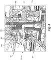
- FIG. 4 is a cross-sectional view of AOA vane 18, mounting system 20, and electric isolator 22".
- AOA vane 18 includes vane body 24, shaft 26.
- Mounting system 20 includes outboard mounting flange 28', inboard mounting flange 30', outboard bearing 32, and inboard bearing 34.
- Outboard bearing 32 includes outer race 40a, inner race 42a, and ball 44a.
- Inboard bearing 34 outer race 40b, inner race 42b, and ball 44b.
- Outboard mounting flange 28' includes flange notch 52a
- inboard mounting flange 30' includes flange notch 52b.
- Electric isolator 22" includes outer dielectric sleeve 54a and outer dielectric sleeve 54b.
- Mounting system 20 is attached to fuselage 12 (shown in FIG. 1 ) and supports AOA vane 18.
- Outboard mounting flange 28' is disposed on an outward side of fuselage 12 and inboard mounting flange 30' is disposed on an inboard side of fuselage 12.
- Outboard mounting flange 28' is attached to inboard mounting flange 30' to secure mounting system 20 to fuselage 12.
- Shaft 26 extends through outboard mounting flange 28' and inboard mounting flange 30'.
- Flange notch 52a extends annularly about an inner wall of outboard mounting flange 28', and outer dielectric sleeve 54a is disposed within flange notch 52a.
- Flange notch 52b extends annularly about an inner wall of inboard mounting flange 30', and outer dielectric sleeve 54b is disposed within flange notch 52b.
- Outer dielectric sleeve 54a is made from a non-conducting material, such as a ceramic, an engineered plastic, or a composite material.
- outer dielectric sleeve 54b is made from a non-conducting material, such as a ceramic, an engineered plastic, or a composite material.
- Outboard bearing 32 is disposed between outboard mounting flange 28' and shaft 26 and rotationally supports shaft 26 relative to outboard mounting flange 28'.
- Outer race 40a is disposed on outer dielectric sleeve 54a, which is connected to outboard mounting flange 28' and disposed within flange notch 52a.
- Inner race 42a is attached to shaft 26, and ball 44a is disposed between outer race 40a and inner race 42a.
- Inboard bearing 34 is disposed between inboard mounting flange 30' and shaft 26 and rotationally supports shaft 26 relative to inboard mounting flange 30'.
- Outer race 40b is disposed on outer dielectric sleeve 54b, which is connected to inboard mounting flange 30' and disposed within flange notch 52b.
- Inner race 42b is attached to shaft 26, and ball 44b is disposed between outer race 40b and inner race 42b.
- vane body 24 projects outboard of fuselage 12, and outboard mounting flange 28' similarly is exposed to the environment outboard of fuselage 12. As such, vane body 24 and outboard mounting flange 28' are exposed and can attract lightning strikes.
- vane body 24 or outboard mounting flange 28' the electric current attempts to travel to the metallic skin of fuselage 12.
- the electrical current travels down vane body 24 and along shaft 26. From shaft 26 the electrical current generally travels through outboard bearing 32 and inboard bearing 34 because outboard bearing 32 and inboard bearing 34 present the path of least resistance to the electrical current.
- outboard mounting flange 28' when lightning strikes outboard mounting flange 28', the path of least electrical resistance for the electrical current to travel through is through outboard bearing 32, inboard bearing 34, or both. Whether the lightning strikes vane body 24 or outboard mounting flange 28' the electrical current can arc across outboard bearing 32, between outer race 40a and inner race 42a, thereby creating EDM pits in outer race 40a and inner race 42a. The electrical current can also arc across inboard bearing 34, between outer race 40b and inner race 42b, and create EDM pits in outer race 40b and inner race 42b. The EDM pits in both outboard bearing 32 can cause friction and can lead to premature bearing of AOA vane failure.
- Electric isolator 22" prevents an electrical current associated with a lightning strike, which may exceed 130 kilovolts, from passing through either outboard bearing 32 or inboard bearing 34.
- Outer dielectric sleeve 54a provides a dielectric barrier between outer race 40a and outboard mounting flange 28'.
- Outer dielectric sleeve 54a electrically isolates outboard bearing 32 to prevent any voltage, from stray electrical currents to those generated by a lightning strike, from passing through and damaging outboard bearing 32 between inner race 42a and outer race 40a. In this way, outer dielectric sleeve 54a prevents electrical current from flowing through outboard bearing 32, as the electric current cannot pass through outer dielectric sleeve 54a.
- Outer dielectric sleeve 54a thus breaks any electrical pathway through outboard bearing 32, thereby protecting outboard bearing 32 from electrical currents.
- outer dielectric sleeve 54b provides a dielectric barrier between outer race 40b and inboard mounting flange 30'.
- Outer dielectric sleeve 54 is disposed between outer race 40b and inboard mounting flange 30' such that outer dielectric sleeve 54 contacts outer race 40 while preventing inboard mounting flange 30' and outer race 40b from coming into contact.
- Outer dielectric sleeve 54b electrically isolates inboard bearing 34 such that any voltage, from stray electrical currents to those generated by a lightning strike, is prevented from passing through and damaging inboard bearing 34.
- outer dielectric sleeve 54b prevents electrical current from flowing through inboard bearing 34 as the electrical current cannot pass through outer dielectric sleeve 54b. Outer dielectric sleeve 54b thus breaks any electrical pathway through inboard bearing 34, thereby protecting inboard bearing 34 from electrical currents.
- Electric isolator 22" provides significant advantages.
- Outer dielectric sleeve 54a and outer dielectric sleeve 54b protect outboard bearing 32 and inboard bearing 34 from induced voltages caused by lightning strikes, which can reach upwards of 130 kilovolts.
- outer dielectric sleeve 54a and outer dielectric sleeve 54b provide robust electrical protection.
- FIG. 5 is a cross-sectional view of AOA vane 18, mounting system 20, and electric isolator 22'''.
- AOA vane 18 includes vane body 24, shaft 26.
- Mounting system 20 includes outboard mounting flange 28, inboard mounting flange 30, outboard bearing 32, and inboard bearing 34.
- Mounting system 20 further includes rotary position sensor 36 and damper 38.
- Outboard bearing 32 includes outer race 40a, inner race 42a, and ball 44a.
- Inboard bearing 34 outer race 40b, inner race 42b, and ball 44b.
- Mounting system 20 is attached to fuselage 12 (shown in FIG. 1 ) and supports AOA vane 18.
- Outboard mounting flange 28 is disposed outward of and secured to inboard mounting flange 30.
- Shaft 26 extends through outboard mounting flange 28 and inboard mounting flange 30 and communicates with rotary position sensor 36.
- Rotary position sensor 36 is inboard of shaft 26 and is configured to sense a rotational displacement of shaft 26.
- Damper 38 extends about shaft 26 and typically includes a viscous fluid, such as oil, that dampens the rotation of shaft 26 and any vibrations experienced by shaft 26.
- Outboard bearing 32 is attached to both outboard mounting flange 28 and shaft 26 and rotationally supports shaft 26 relative to outboard mounting flange 28.
- Outer race 40a is attached to outboard mounting flange 28 and inner race 42a is attached to shaft 26.
- Ball 44a is disposed between outer race 40a and inner race 42a and supports outer race 40a and inner race 42a such that inner race 42a rotates relative to outer race 40a.
- Inboard bearing 34 is attached to both inboard mounting flange 30 and shaft 26 and rotationally supports shaft 26 relative to inboard mounting flange 30.
- Outer race 40b is attached to inboard mounting flange 30 and inner race 42b is attached to shaft 26.
- Ball 44b is disposed between outer race 40b and inner race 42b and supports outer race 40b and inner race 42b such that inner race 42b is free to rotate relative to outer race 40b.
- Electric isolator 22'" is connected to shaft 26 and is electrically connected to outboard mounting flange 28.
- Electric isolator 22'" is a grounding device, such as a grounding ring or a grounding brush, connected to shaft 26.
- Electric isolator 22''' provides an alternate low-impedance path from shaft 26 to outboard mounting flange 28, and thus to the skin of fuselage 12 (shown in FIG. 1 ).
- Electric isolator 22''' thus reduces or eliminates voltage on shaft 26, and thus on outboard bearing 32 and inboard bearing 34, by preventing voltage from building on shaft 26. As such, the electrical current generated by a lightning strike is routed away from outboard bearing 32 and inboard bearing 34, thereby protecting both outboard bearing 32 and inboard bearing 34.
- An angle of attack vane mounting system includes a mounting flange secured to an aircraft; a shaft extending through the mounting flange; a bearing disposed between the mounting flange and the shaft, wherein the bearing includes an inner race attached to the shaft and an outer race attached to the mounting flange; and an electric isolator disposed adjacent one of the inner race and the outer race and electrically isolating the bearing such that an electric current is prevented from passing between the inner race and the outer race.
- the angle of attack vane mounting system of the preceding paragraph can optionally include, additionally and/or alternatively, any one or more of the following features, configurations and/or additional components:
- the electric isolator comprises a sleeve disposed between the shaft and the inner race.
- the electric isolator comprises a sleeve disposed between the mounting flange and the outer race.
- the electric isolator comprises a ceramic rolling element disposed between the inner race and the outer race.
- the shaft comprises a dielectric material.
- An angle of attack vane for an aircraft an outboard mounting flange; an inboard mounting flange disposed adjacent the outboard mounting flange; a shaft extending through the outboard mounting flange and the inboard mounting flange; an inboard bearing rotatably supporting the shaft and disposed between the shaft and the inboard mounting flange; an inboard electric isolator configured to prevent an electric current from traveling through the inboard bearing; an outboard bearing rotatably supporting the shaft and disposed between the outboard mounting flange and the shaft; an outboard electric isolator configured to prevent an electric current from traveling through the outboard bearing; and a vane extending from the shaft outboard of the outboard mounting flange.
- the angle of attack vane of the preceding paragraph can optionally include, additionally and/or alternatively, any one or more of the following features, configurations and/or additional components:
- the inboard electric isolator includes a ceramic inboard rolling ball disposed between an inboard outer race of the inboard bearing and an inboard outer race of the bearing, wherein the ceramic inboard rolling ball is configured to prevent an electric current from passing between the inboard inner race and the inboard outer race.
- the inboard inner race is a dielectric material and the inboard outer race is the dielectric material.
- the dielectric material comprises one of a ceramic, an engineered plastic, or a composite material.
- a grounding brush is disposed about the shaft and configured to ground the shaft to a fuselage of the aircraft.
- the inboard electric isolator includes a first sleeve disposed about the shaft and adjacent an inboard inner race of the inboard bearing, and the outboard electric isolator comprises a second sleeve disposed about the shaft and adjacent an outboard inner race of the outboard bearing.
- the inboard electric isolator comprises a first sleeve disposed between the inboard mounting flange and an inboard inner race of the inboard bearing
- the outboard electric isolator comprises a second sleeve disposed between the outboard mounting flange and an outboard inner race of the outboard bearing.
- the outboard mounting flange comprises a dielectric material.
- the shaft comprises a dielectric material.
- the inboard mounting flange comprises a dielectric material.
- a method of preventing lightning strike damage to a bearing of an angle of attack vane includes mounting an angle of attack vane shaft on a bearing disposed between the angle of attack vane shaft and a mounting flange, and electrically isolating the bearing such that an electrical current cannot pass between an inner race of the bearing and an outer race of the bearing.
- the method of the preceding paragraph can optionally include, additionally and/or alternatively, any one or more of the following features, configurations and/or additional components: Mounting a ceramic rolling element between the inner race and the outer race.
Landscapes
- Engineering & Computer Science (AREA)
- General Engineering & Computer Science (AREA)
- Aviation & Aerospace Engineering (AREA)
- Mechanical Engineering (AREA)
- Ceramic Engineering (AREA)
- Physics & Mathematics (AREA)
- General Physics & Mathematics (AREA)
- Motor Or Generator Frames (AREA)
- Rolling Contact Bearings (AREA)
- Wind Motors (AREA)
- Elimination Of Static Electricity (AREA)
Description
- The present disclosure relates generally to electrically isolating angle of attack vanes. More particularly, this disclosure relates to electrically isolating the bearings of angle of attack vanes.
- Angular measurement devices, such as angle of attack (AOA) and side slip angle (SSA) vanes, project from an aircraft body and are free to rotate and align with the prevailing airflow. The angular measurement vane rotates with the prevailing airflow and provides such rotational information to electronics within the aircraft. The trajectory of the aircraft and the degree of rotation of the angular measurement vane is used to calculate the angle of attack or the side slip angle of the aircraft, and such information is provided to the cockpit and to relevant systems on the aircraft.
- Angular measurement vanes project outside of the aircraft and into the prevailing airflow. Typically, a shaft extends into the aircraft body from the angular measurement vane and into an electronics enclosure, where electronics measure the rotational displacement of the shaft. Bearings rotatably support the shaft relative to mounting hardware, which mounting hardware is secured to the body of the aircraft. The shaft is thus free to rotate relative to the mounting hardware such that the angular measurement vane is free to rotate with the prevailing airflow. The angular measurement vane, shaft, bearings, and mounting hardware are typically metallic, and the vane and mounting hardware are exposed to the environment, and as such, are particularly susceptible to lightning strikes. The electrical current from a lightning strike on the vane, mounting hardware, or other locations on the aircraft body can pass through the bearings of the angular measurement vane. The large electrical current generated by a lightning strike, which can exceed 130 kilovolts, arcs through the bearings of the angular measurement vane and can cause fluting damage, which can lead to rough or stiff bearing failures.
- According to an aspect of the present disclosure, an angle of attack vane mounting system includes a mounting flange secured to an aircraft, a shaft extending through the mounting flange, a bearing disposed between the mounting flange and the shaft, and an electric isolator. The bearing includes an inner race attached to the shaft and an outer race attached to the mounting flange. The electric isolator is disposed adjacent one of the inner race and the outer race and electrically isolates the bearing such that an electric current is prevented from passing between the inner race and the outer race. Such electrically isolating bearings in itself are known for example from
US2001048781 . - According to another aspect of the present disclosure, an angle of attack vane for an aircraft includes an outboard mounting flange, an inboard mounting flange disposed adjacent the outboard mounting flange, a shaft extending through the outboard mounting flange and the inboard mounting flange, an inboard bearing rotatably supporting the shaft and disposed between the shaft and the inboard mounting flange, an inboard electric isolator configured to prevent an electric current from traveling through the inboard bearing, an outboard bearing rotatably supporting the shaft and disposed between the outboard mounting flange and the shaft, an outboard electric isolator configured to prevent an electric current from traveling through the outboard bearing, and a vane extending from the shaft outboard of the outboard mounting flange.
- According to yet another aspect of the present disclosure, a method of preventing lightning strike damage to a bearing of an angle of attack vane includes mounting an angle of attack vane shaft on a bearing disposed between the angle of attack vane shaft and a mounting flange and electrically isolating the bearing such that an electrical current cannot pass between an inner race of the bearing and an outer race of the bearing.
-
-
FIG. 1 is a perspective view of an aircraft. -
FIG. 2 is a cross-sectional view of an angle of attack vane mounting system having a first electric isolator. -
FIG. 3 is a cross-sectional view of an angle of attack vane mounting system having a second electric isolator. -
FIG. 4 is a cross-sectional view of an angle of attack vane mounting system having a third electric isolator. -
FIG. 5 is a cross-sectional view of an angle of attack vane mounting system and a grounding element. -
FIG. 1 is a perspective view ofaircraft 10.Aircraft 10 includesfuselage 12,wings 14, andengines 16.Fuselage 12 includes angle of attack (AOA)vane 18. AOA vane 18 projects fromfuselage 12 forward ofwings 14. - During flight, AOA
vane 18 rotates to align with the prevailing airflow. AOA vane 18 is preferably located forward ofwings 14. Locating AOAvane 18 forward ofwings 14 minimizes the effects onAOA vane 18 of the airflow affected byfuselage 12,wings 14, orengines 16, thereby ensuring the accuracy ofAOA vane 18. For example, asaircraft 10 ascends, AOAvane 18 aligns with the prevailing airflow and indicates a high angle of attack. Asaircraft 10 approaches a cruise altitude AOA vane 18 continues to track with the prevailing airflow, and AOAvane 18 thus indicates a lower angle of attack asaircraft 10 levels off. Because AOA vane 18 projects fromfuselage 12, AOA vane 18 is exposed to the elements and is particularly susceptible to lighting strikes. When lightning strikes AOA vane 18 the electrical current generated by the lightning strike travels through AOAvane 18 and seeks a low-impedance path tofuselage 12. WhileAOA vane 18 is described as measuring the angle of attack, it is understood thatAOA vane 18 may be any angular sensing instrument, such as an AOA vane or a side slip angle vane. -
FIG. 2 is a cross-sectional view ofAOA vane 18,mounting system 20, andelectric isolator 22. AOA vane 18 includesvane body 24 andshaft 26.Mounting system 20 includesoutboard mounting flange 28,inboard mounting flange 30, outboard bearing 32, and inboard bearing 34.Mounting system 20 further includesrotary position sensor 36 anddamper 38. Outboard bearing 32 includesouter race 40a,inner race 42a, andball 44a. Inboard bearing 34outer race 40b,inner race 42b, andball 44b.Electric isolator 22 may includedielectric barrier 46a,dielectric barrier 46b,dielectric barrier 46c, anddielectric barrier 46d. -
Mounting system 20 is attached to fuselage 12 (shown inFIG. 1 ) and supports AOAvane 18.Outboard mounting flange 28 is disposed outward of and secured toinboard mounting flange 30. Shaft 26 extends throughoutboard mounting flange 28 andinboard mounting flange 30 and communicates withrotary position sensor 36.Rotary position sensor 36 is inboard ofshaft 26 and is configured to sense a rotational displacement ofshaft 26.Damper 38 extends aboutshaft 26 and typically includes a viscous fluid, such as oil, that dampens the rotation ofshaft 26, and thusAOA vane 18, to slow the response time ofAOA vane 18 to changes in airflow direction. As such,damper 38 ensures a smooth rotation ofAOA vane 18, thus providing a smooth reading of the angle of attack. In addition, the damping fluid indamper 38 absorbs oscillations experienced byshaft 26, such as those vibrations experienced due to turbulence, and prevents variations in the angle of attack readings due to unwanted vibrations inshaft 26. - Outboard bearing 32 is disposed between
outboard mounting flange 28 andshaft 26 and rotationally supportsshaft 26 relative tooutboard mounting flange 28.Outer race 40a is attached tooutboard mounting flange 28 andinner race 42a is attached toshaft 26. Ball 44a is disposed betweenouter race 40a andinner race 42a and supportsouter race 40a and inner race 42 such thatinner race 42a rotates relative toouter race 40a. Inboard bearing 34 is disposed betweeninboard mounting flange 30 andshaft 26 and rotationally supportsshaft 26 relative toinboard mounting flange 30.Outer race 40b is attached toinboard mounting flange 30 andinner race 42b is attached toshaft 26. Ball 44b is disposed betweenouter race 40b andinner race 42b and supportsouter race 40b andinner race 42b such thatinner race 42b is free to rotate relative toouter race 40b. -
Mounting system 20 is attached to fuselage 12 (shown inFIG. 1 ). AOA vane 18 is rotatably supported bymounting system 20 withvane body 24 disposed outboard offuselage 12 andshaft 26 supported bymounting system 20.Outboard mounting flange 28 is typically mounted on an exterior offuselage 12 andinboard mounting flange 30 is mounted opposite of and attached tooutboard mounting flange 28. In this way,outboard mounting flange 28 andinboard mounting flange 30 are attached tofuselage 12 to securemounting system 20 and AOAvane 18 tofuselage 12. - During flight, the prevailing airflow flows over
vane body 24 andvane body 24 rotates to align with the prevailing airflow.Vane body 24 aligning with the prevailing airflow causesshaft 26 to rotate, and rotary position sensor senses the rotational movement ofshaft 26.Rotary position sensor 36 senses the rotational displacement ofshaft 26 and communicates that information to other systems on aircraft 10 (shown inFIG. 1 ). The rotational displacement ofshaft 26 and other information regarding the trajectory ofaircraft 10 is used by the other systems onboardaircraft 10 to calculate the angle of attack, side slip angle, and the true direction ofaircraft 10 travel, among other relevant information. -
Vane body 24 and outboard mountingflange 28 are disposed outboard offuselage 12, and as such,vane body 24 and outboard mountingflange 28 are exposed and can attract lightning strikes. When lightning strikesvane body 24 oroutboard mounting flange 28, the electrical current seeks the path of least resistance to the metallic aircraft skin, which path of least resistance is typically throughoutboard bearing 32,inboard bearing 34, or both. The voltage generated by the lighting strike builds oninner race 42a orouter race 40a until the voltage exceeds an insulation level of an oil film layer withinoutboard bearing 32. When the voltage exceeds the insulation level, the voltage arcs throughoutboard bearing 32 and creates electrical discharge machining (EDM) pits oninner race 42a andouter race 40a due to rapid melting and cooling of the metallicinner race 42a andouter race 40a. Thousands of EDM pits may be created, and overtime ball 44a rolling over the EDM pits can cause fluting damage tooutboard bearing 32. In addition, the EDM pits can cause friction withinoutboard bearing 32. While the effects of a lightning strike onoutboard bearing 32 have been described, it is understood that the effects of the lightning strike are equally applicable toinboard bearing 34. As such, a single lightning strike can create EDM pits in bothoutboard bearing 32 andinboard bearing 34. -
Electric isolator 22 prevents the electrical current associated with a lightning strike, which may exceed 130 kilovolts, from arcing across eitheroutboard bearing 32; thereby damagingouter race 40a,inner race 42a, orball 44a; orinboard bearing 34; thereby damagingouter race 40b,inner race 42b, orball 44b. -
Dielectric barrier 46a may be formed from the components ofoutboard bearing 32 orinboard bearing 34. As such,dielectric barrier 46a may take the form of a hybrid bearing or a fully non-conducting bearing. For example,ball 44a disposed betweenouter race 40a andinner race 42a may be comprised of a material formingdielectric barrier 46a. Whereball 44a is formed of the material, preferably a ceramic, formingdielectric barrier 46a,ball 44a forms a non-conducting barrier preventing electrical current from arcing betweenouter race 40a andinner race 42a.Dielectric barrier 46a may further include a ceramicouter race 40a and a ceramicinner race 42a, and in this way,outboard bearing 32 is a fully non-conducting bearing. By havingdielectric barrier 46a be aceramic ball 44a, a ceramicouter race 40a, a ceramicinner race 42a, or a combination thereof, electric currents are not conducted throughoutboard bearing 32, andoutboard bearing 32 is thus protected from the high voltage of a lightning strike. Whiledielectric barrier 46a has been described in relation tooutboard bearing 32, it is understood thatdielectric barrier 46a applies equally toinboard bearing 34 such that one or more ofball 44b,outer race 40b, andinner race 42b may be formed of a non-conducting material, such as ceramic, to formdielectric barrier 46a. - Hybrid bearings, where
ball 44a formsdielectric barrier 46a whileouter race 40a andinner race 42a remain conducting, and all-dielectric bearings, whereball 44a,outer race 40a, andinner race 42a formdielectric barrier 46a, provide significant advantages. Hybrid bearings provide a higher load rating than all-metal counterparts, thereby increasing the durability and lifespan of the bearings. In addition, hybrid bearings and all-dielectric bearings prevent all electrical currents from passing through the bearing over the expected range of lightning strike voltage. As such, hybrid and all-dielectric bearings both increase the lifespan and utility ofoutboard bearing 32 andinboard bearing 34, and consequently ofAOA vane 18, and preventoutboard bearing 32 and inboard bearing 34 from being damaged by any electrical signal, whether from a lightning strike or from induced electrical currents, such as those created by variable frequency generators, for example. - Similar to
dielectric barrier 46a,dielectric barrier 46b prevents the electrical current associated with a lightning strike from arcing across eitheroutboard bearing 32 orinboard bearing 34.Dielectric barrier 46b forms a shaft-side non-conducting barrier. To formdielectric barrier 46b,shaft 26 is constructed from a monolithic, dielectric material. For example,shaft 26 may be formed from a ceramic, an engineered plastic, or a non-conductive composite material. Having a monolithic,non-conductive shaft 26 prevents an electrical path from forming throughshaft 26 and to eitheroutboard bearing 32 orinboard bearing 34. In this way,dielectric barrier 46b thereby prevents the electric current from flowing through and damagingoutboard bearing 32 andinboard bearing 34. -
Dielectric barrier 46c similarly prevents an electrical current associated with a lightning strike from arcing between and damaginginner race 42a andouter race 40a.Dielectric barrier 46c forms an outboard mounting flange-side non-conducting barrier aboutouter race 40a. To formdielectric barrier 46c, outboard mountingflange 28 is formed from a monolithic, dielectric material. As such, outboard mountingflange 28 is preferably comprised of a ceramic, an engineered plastic, or a non-conductive composite material.Dielectric barrier 46c electrically isolatesouter race 40a to prevent an electric current from flowing throughouter race 40a. As such,outboard bearing 32 is electrically isolated such that no electric current can flow throughoutboard bearing 32 betweeninner race 42a andouter race 40a. As such,dielectric barrier 46c prevents outboard bearing 32 from sustaining EDM damage due to lightning strikes. - Similar to
dielectric barrier 46c,dielectric barrier 46d electrically isolatesouter race 40b and prevents an electrical current associated with a lightning strike from arcing between and damaginginner race 42b andouter race 40b.Dielectric barrier 46d forms an inboard mounting flange-side non-conducting barrier aboutouter race 40b. To formdielectric barrier 46d, inboard mountingflange 30 preferably comprises a ceramic, an engineered plastic, or a non-conductive composite material. As such, inboard mountingflange 30 formsdielectric barrier 46d, and inboard mountingflange 30 electrically isolatesouter race 40b, thereby preventing an electric current from flowing throughouter race 40b.Inboard bearing 34 is thus electrically isolated such that an electric current cannot flow throughinboard bearing 34 betweeninner race 42b andouter race 40b. As such,dielectric barrier 46d prevents inboard bearing 34 from sustaining EDM damage caused by lightning strikes. - While
electric isolator 22 is described as includingdielectric barrier 46a,dielectric barrier 46b,dielectric barrier 46c, anddielectric barrier 46d, it is understood thatelectric isolator 22 may include as few or as many ofdielectric barriers 46a-d as desired. For example,dielectric barrier 46a prevents an electric current from arcing betweenouter race 40a andinner race 42a by having one or more ofball 44a,outer race 40a, andinner race 42a consist of a ceramic material. As such,dielectric barrier 46a provides sufficient electrical protection tooutboard bearing 32 andinboard bearing 34 to preventoutboard bearing 32 and inboard bearing 34 from sustaining lightning strike damage.Dielectric barrier 46a is thus sufficiently robust to protectoutboard bearing 32 andinboard bearing 34 and electric isolator may thus includedielectric barrier 46a alone. Similarly,dielectric barrier 46b,dielectric barrier 46c, anddielectric barrier 46d provide sufficient electrical protection tooutboard bearing 32 andinboard bearing 34 to preventoutboard bearing 32 and inboard bearing 34 from sustaining lightning strike damage. Therefore,electric isolator 22 may include any one or more ofdielectric barrier 46a,dielectric barrier 46b,dielectric barrier 46c, anddielectric barrier 46d. -
Electric isolator 22 provides significant advantages.Electric isolator 22 provides increased strength and durability to mountingsystem 20 andAOA vane 18 by including monolithic, non-conductingdielectric barriers dielectric barriers system 20 andAOA vane 18, such asrotary position sensor 36 and other electronic components. In addition, various combinations ofdielectric barriers dielectric barrier 46a anddielectric barrier 46b protects not onlyoutboard bearing 32 and inboard bearing 34 from induced voltages, but also protectsrotary position sensor 36, as well as other electronics, because induced voltages cannot pass throughshaft 26 due todielectric barrier 46b. -
FIG. 3 is a cross-sectional view ofAOA vane 18, mountingsystem 20, and electric isolator 22'.AOA vane 18 includesvane body 24, shaft 26'. Mountingsystem 20 includes outboard mountingflange 28, inboard mountingflange 30,outboard bearing 32, andinboard bearing 34. Outboard bearing 32 includesouter race 40a,inner race 42a, andball 44a.Inboard bearing 34outer race 40b,inner race 42b, andball 44b. Shaft 26' includesannular notch 48a andannular notch 48b. Electric isolator 22' includes innerdielectric sleeve 50a and innerdielectric sleeve 50b. - Mounting
system 20 is attached to fuselage 12 (shown inFIG. 1 ) and supportsAOA vane 18. Outboard mountingflange 28 is disposed on an outward side offuselage 12 and inboard mountingflange 30 is disposed on an inboard side offuselage 12. Outboard mountingflange 28 is attached to inboard mountingflange 30 to secure mountingsystem 20 tofuselage 12. Shaft 26' extends through outboard mountingflange 28 and inboard mountingflange 30.Annular notch 48a extends into shaft 26' adjacentoutboard bearing 32, andannular notch 48b extends into shaft 26' adjacentinboard bearing 34. - Outboard bearing 32 is disposed between outboard mounting
flange 28 and shaft 26' and rotatably supportsshaft 26 relative to outboard mountingflange 28.Outer race 40a is disposed on outboard mountingflange 28 andinner race 42a is disposed on shaft 26' aboutannular notch 48a. Innerdielectric sleeve 50a is disposed withinannular notch 48a betweeninner race 42a and shaft 26' such thatinner race 42a abuts innerdielectric sleeve 50a. Innerdielectric sleeve 50a preventsinner race 42a from contacting shaft 26'.Ball 44a is disposed betweenouter race 40a andinner race 42a and rotatably supportsouter race 40a and inner race 42. -
Inboard bearing 34 is disposed betweeninboard mounting flange 30 and shaft 26' and rotatably supports shaft 26' relative to inboard mountingflange 30.Outer race 40b is disposed oninboard mounting flange 30 andinner race 42b is disposed on shaft 26' aboutannular notch 48b. Innerdielectric sleeve 50b is disposed withinannular notch 48b betweeninner race 42b and shaft 26' such thatinner race 42b contacts innerdielectric sleeve 50b, but innerdielectric sleeve 50b preventsinner race 42b from contacting shaft 26'.Ball 44b is disposed betweenouter race 40b andinner race 42b and rotatably supportsouter race 40b andinner race 42b such thatinner race 42b is free to rotate relative toouter race 40b. Innerdielectric sleeve 50a and innerdielectric sleeve 50b are formed from a non-conductive material such that an electric current cannot pass through either innerdielectric sleeve 50a or innerdielectric sleeve 50b. -
Vane body 24 and outboard mountingflange 28 are disposed outboard offuselage 12, and as such,vane body 24 and outboard mountingflange 28 are exposed and can attract lightning. When lightning strikesvane body 24 oroutboard mounting flange 28, the electrical current seeks the path of least resistance to the metallic aircraft skin, which path of least resistance is typically throughoutboard bearing 32,inboard bearing 34, or both. When the electrical current travels throughoutboard bearing 32, the electrical current arcs betweenouter race 40a andinner race 42a and can create EDM pits inouter race 40a andinner race 42a. Similarly, the electrical current can arc acrossinboard bearing 34 betweenouter race 40b andinner race 42b and create EDM pits inouter race 40b andinner race 42b. - Electric isolator 22' prevents the electrical current associated with a lightning strike, which may exceed 130 kilovolts, from arcing across either
outboard bearing 32 orinboard bearing 34. Innerdielectric sleeve 50a provides a first dielectric barrier aboutshaft 26 between shaft 26' andinner race 42a such that no electric current can travel betweeninner race 42a and shaft 26'. As such, innerdielectric sleeve 50a prevents the electric current from passing throughoutboard bearing 32 because the electric current cannot pass through innerdielectric sleeve 50a betweeninner race 42a and shaft 26'. Innerdielectric sleeve 50a thus electrically isolatesoutboard bearing 32 such that the electric current generated by a lightning strike cannot travel throughoutboard bearing 32, thereby preventing outboard bearing 32 from being damaged due to a lightning strike. - Similar to inner
dielectric sleeve 50a, innerdielectric sleeve 50b provides a second dielectric barrier aboutshaft 26, between shaft 26' andinner race 42b such that no electric current can travel betweeninner race 42b and shaft 26'. As such, innerdielectric sleeve 50b prevents the electric current from passing throughoutboard bearing 32 because the electric current cannot pass through innerdielectric sleeve 50b betweeninner race 42b and shaft 26'. Innerdielectric sleeve 50b thus electrically isolatesinboard bearing 34 such that the electric current generated by a lightning strike cannot travel throughinboard bearing 34, thereby preventing inboard bearing 34 from being damaged due to a lightning strike. - Electric isolator 22' provides significant advantages. Inner
dielectric sleeve 50a and innerdielectric sleeve 50b protectoutboard bearing 32 and inboard bearing 34 from induced voltages caused by lightning strikes, which can reach upwards of 130 kilovolts. Unlike a ceramic coating oninner race 42a orinner race 42b, which may protect for voltages up to about 3 kilovolts, innerdielectric sleeve 50a and innerdielectric sleeve 50b provide robust electrical protection. -
FIG. 4 is a cross-sectional view ofAOA vane 18, mountingsystem 20, andelectric isolator 22".AOA vane 18 includesvane body 24,shaft 26. Mountingsystem 20 includes outboard mounting flange 28', inboard mounting flange 30', outboard bearing 32, andinboard bearing 34. Outboard bearing 32 includesouter race 40a,inner race 42a, andball 44a.Inboard bearing 34outer race 40b,inner race 42b, andball 44b. Outboard mounting flange 28' includesflange notch 52a, and inboard mounting flange 30' includesflange notch 52b.Electric isolator 22" includes outerdielectric sleeve 54a and outerdielectric sleeve 54b. - Mounting
system 20 is attached to fuselage 12 (shown inFIG. 1 ) and supportsAOA vane 18. Outboard mounting flange 28' is disposed on an outward side offuselage 12 and inboard mounting flange 30' is disposed on an inboard side offuselage 12. Outboard mounting flange 28' is attached to inboard mounting flange 30' to secure mountingsystem 20 tofuselage 12.Shaft 26 extends through outboard mounting flange 28' and inboard mounting flange 30'.Flange notch 52a extends annularly about an inner wall of outboard mounting flange 28', and outerdielectric sleeve 54a is disposed withinflange notch 52a.Flange notch 52b extends annularly about an inner wall of inboard mounting flange 30', and outerdielectric sleeve 54b is disposed withinflange notch 52b. Outerdielectric sleeve 54a is made from a non-conducting material, such as a ceramic, an engineered plastic, or a composite material. Similarly, outerdielectric sleeve 54b is made from a non-conducting material, such as a ceramic, an engineered plastic, or a composite material. - Outboard bearing 32 is disposed between outboard mounting flange 28' and
shaft 26 and rotationally supportsshaft 26 relative to outboard mounting flange 28'.Outer race 40a is disposed on outerdielectric sleeve 54a, which is connected to outboard mounting flange 28' and disposed withinflange notch 52a.Inner race 42a is attached toshaft 26, andball 44a is disposed betweenouter race 40a andinner race 42a.Inboard bearing 34 is disposed between inboard mounting flange 30' andshaft 26 and rotationally supportsshaft 26 relative to inboard mounting flange 30'.Outer race 40b is disposed on outerdielectric sleeve 54b, which is connected to inboard mounting flange 30' and disposed withinflange notch 52b.Inner race 42b is attached toshaft 26, andball 44b is disposed betweenouter race 40b andinner race 42b. - During flight, air flows over
vane body 24 andvane body 24 rotates to align with the prevailing airflow.Vane body 24 projects outboard offuselage 12, and outboard mounting flange 28' similarly is exposed to the environment outboard offuselage 12. As such,vane body 24 and outboard mounting flange 28' are exposed and can attract lightning strikes. When lightning strikesvane body 24 or outboard mounting flange 28' the electric current attempts to travel to the metallic skin offuselage 12. When lightning strikesvane body 24, the electrical current travels downvane body 24 and alongshaft 26. Fromshaft 26 the electrical current generally travels throughoutboard bearing 32 andinboard bearing 34 becauseoutboard bearing 32 andinboard bearing 34 present the path of least resistance to the electrical current. Similarly, when lightning strikes outboard mounting flange 28', the path of least electrical resistance for the electrical current to travel through is throughoutboard bearing 32,inboard bearing 34, or both. Whether the lightning strikes vanebody 24 or outboard mounting flange 28' the electrical current can arc acrossoutboard bearing 32, betweenouter race 40a andinner race 42a, thereby creating EDM pits inouter race 40a andinner race 42a. The electrical current can also arc acrossinboard bearing 34, betweenouter race 40b andinner race 42b, and create EDM pits inouter race 40b andinner race 42b. The EDM pits in both outboard bearing 32 can cause friction and can lead to premature bearing of AOA vane failure. -
Electric isolator 22" prevents an electrical current associated with a lightning strike, which may exceed 130 kilovolts, from passing through eitheroutboard bearing 32 orinboard bearing 34. Outerdielectric sleeve 54a provides a dielectric barrier betweenouter race 40a and outboard mounting flange 28'. Outerdielectric sleeve 54a electrically isolatesoutboard bearing 32 to prevent any voltage, from stray electrical currents to those generated by a lightning strike, from passing through and damagingoutboard bearing 32 betweeninner race 42a andouter race 40a. In this way, outerdielectric sleeve 54a prevents electrical current from flowing throughoutboard bearing 32, as the electric current cannot pass through outerdielectric sleeve 54a. Outerdielectric sleeve 54a thus breaks any electrical pathway throughoutboard bearing 32, thereby protecting outboard bearing 32 from electrical currents. - Similar to outer
dielectric sleeve 54a, outerdielectric sleeve 54b provides a dielectric barrier betweenouter race 40b and inboard mounting flange 30'. Outer dielectric sleeve 54 is disposed betweenouter race 40b and inboard mounting flange 30' such that outer dielectric sleeve 54 contacts outer race 40 while preventing inboard mounting flange 30' andouter race 40b from coming into contact. Outerdielectric sleeve 54b electrically isolatesinboard bearing 34 such that any voltage, from stray electrical currents to those generated by a lightning strike, is prevented from passing through and damaginginboard bearing 34. In this way, outerdielectric sleeve 54b prevents electrical current from flowing throughinboard bearing 34 as the electrical current cannot pass through outerdielectric sleeve 54b. Outerdielectric sleeve 54b thus breaks any electrical pathway throughinboard bearing 34, thereby protecting inboard bearing 34 from electrical currents. -
Electric isolator 22" provides significant advantages. Outerdielectric sleeve 54a and outerdielectric sleeve 54b protectoutboard bearing 32 and inboard bearing 34 from induced voltages caused by lightning strikes, which can reach upwards of 130 kilovolts. Unlike a ceramic coating onouter race 40a orouter race 40b, which may protect for voltages up to about 3 kilovolts, outerdielectric sleeve 54a and outerdielectric sleeve 54b provide robust electrical protection. -
FIG. 5 is a cross-sectional view ofAOA vane 18, mountingsystem 20, and electric isolator 22'''.AOA vane 18 includesvane body 24,shaft 26. Mountingsystem 20 includes outboard mountingflange 28, inboard mountingflange 30,outboard bearing 32, andinboard bearing 34. Mountingsystem 20 further includesrotary position sensor 36 anddamper 38. Outboard bearing 32 includesouter race 40a,inner race 42a, andball 44a.Inboard bearing 34outer race 40b,inner race 42b, andball 44b. - Mounting
system 20 is attached to fuselage 12 (shown inFIG. 1 ) and supportsAOA vane 18. Outboard mountingflange 28 is disposed outward of and secured to inboard mountingflange 30.Shaft 26 extends through outboard mountingflange 28 and inboard mountingflange 30 and communicates withrotary position sensor 36.Rotary position sensor 36 is inboard ofshaft 26 and is configured to sense a rotational displacement ofshaft 26.Damper 38 extends aboutshaft 26 and typically includes a viscous fluid, such as oil, that dampens the rotation ofshaft 26 and any vibrations experienced byshaft 26. Outboard bearing 32 is attached to both outboard mountingflange 28 andshaft 26 and rotationally supportsshaft 26 relative to outboard mountingflange 28.Outer race 40a is attached to outboard mountingflange 28 andinner race 42a is attached toshaft 26.Ball 44a is disposed betweenouter race 40a andinner race 42a and supportsouter race 40a andinner race 42a such thatinner race 42a rotates relative toouter race 40a.Inboard bearing 34 is attached to both inboard mountingflange 30 andshaft 26 and rotationally supportsshaft 26 relative to inboard mountingflange 30.Outer race 40b is attached to inboard mountingflange 30 andinner race 42b is attached toshaft 26.Ball 44b is disposed betweenouter race 40b andinner race 42b and supportsouter race 40b andinner race 42b such thatinner race 42b is free to rotate relative toouter race 40b. Electric isolator 22'" is connected toshaft 26 and is electrically connected to outboard mountingflange 28. - Electric isolator 22'" is a grounding device, such as a grounding ring or a grounding brush, connected to
shaft 26. Electric isolator 22''' provides an alternate low-impedance path fromshaft 26 to outboard mountingflange 28, and thus to the skin of fuselage 12 (shown inFIG. 1 ). Electric isolator 22''' thus reduces or eliminates voltage onshaft 26, and thus onoutboard bearing 32 andinboard bearing 34, by preventing voltage from building onshaft 26. As such, the electrical current generated by a lightning strike is routed away fromoutboard bearing 32 andinboard bearing 34, thereby protecting bothoutboard bearing 32 andinboard bearing 34. - The following are non-exclusive descriptions of possible embodiments of the present invention.
- An angle of attack vane mounting system includes a mounting flange secured to an aircraft; a shaft extending through the mounting flange; a bearing disposed between the mounting flange and the shaft, wherein the bearing includes an inner race attached to the shaft and an outer race attached to the mounting flange; and an electric isolator disposed adjacent one of the inner race and the outer race and electrically isolating the bearing such that an electric current is prevented from passing between the inner race and the outer race.
- The angle of attack vane mounting system of the preceding paragraph can optionally include, additionally and/or alternatively, any one or more of the following features, configurations and/or additional components:
The electric isolator comprises a sleeve disposed between the shaft and the inner race. - The electric isolator comprises a sleeve disposed between the mounting flange and the outer race.
- The electric isolator comprises a ceramic rolling element disposed between the inner race and the outer race.
- The shaft comprises a dielectric material.
- An angle of attack vane for an aircraft an outboard mounting flange; an inboard mounting flange disposed adjacent the outboard mounting flange; a shaft extending through the outboard mounting flange and the inboard mounting flange; an inboard bearing rotatably supporting the shaft and disposed between the shaft and the inboard mounting flange; an inboard electric isolator configured to prevent an electric current from traveling through the inboard bearing; an outboard bearing rotatably supporting the shaft and disposed between the outboard mounting flange and the shaft; an outboard electric isolator configured to prevent an electric current from traveling through the outboard bearing; and a vane extending from the shaft outboard of the outboard mounting flange.
- The angle of attack vane of the preceding paragraph can optionally include, additionally and/or alternatively, any one or more of the following features, configurations and/or additional components:
The inboard electric isolator includes a ceramic inboard rolling ball disposed between an inboard outer race of the inboard bearing and an inboard outer race of the bearing, wherein the ceramic inboard rolling ball is configured to prevent an electric current from passing between the inboard inner race and the inboard outer race. - The inboard inner race is a dielectric material and the inboard outer race is the dielectric material.
- The dielectric material comprises one of a ceramic, an engineered plastic, or a composite material.
- A grounding brush is disposed about the shaft and configured to ground the shaft to a fuselage of the aircraft.
- The inboard electric isolator includes a first sleeve disposed about the shaft and adjacent an inboard inner race of the inboard bearing, and the outboard electric isolator comprises a second sleeve disposed about the shaft and adjacent an outboard inner race of the outboard bearing.
- The inboard electric isolator comprises a first sleeve disposed between the inboard mounting flange and an inboard inner race of the inboard bearing, and the outboard electric isolator comprises a second sleeve disposed between the outboard mounting flange and an outboard inner race of the outboard bearing.
- The outboard mounting flange comprises a dielectric material.
- The shaft comprises a dielectric material.
- The inboard mounting flange comprises a dielectric material.
- A method of preventing lightning strike damage to a bearing of an angle of attack vane includes mounting an angle of attack vane shaft on a bearing disposed between the angle of attack vane shaft and a mounting flange, and electrically isolating the bearing such that an electrical current cannot pass between an inner race of the bearing and an outer race of the bearing.
- The method of the preceding paragraph can optionally include, additionally and/or alternatively, any one or more of the following features, configurations and/or additional components:
Mounting a ceramic rolling element between the inner race and the outer race. - Mounting a grounding element on the shaft adjacent the bearing, such that the shaft is grounded to an aircraft.
- Mounting a dielectric sleeve on the shaft between the shaft and the inner race.
- Mounting a dielectric sleeve on a mounting flange adjacent the outer race of the bearing.
Claims (15)
- An angle of attack vane (18) mounting system (20) comprising:a first mounting flange (28;28') configured to be secured to an aircraft (10);a shaft (26;26') extending through the first mounting flange (28;28');a first bearing (32) disposed between the first mounting flange (28;28') and the shaft (26;26'), wherein the first bearing (32) comprises:a first inner race (42a) attached to the shaft (26;26'); anda first outer race (40a) attached to the first mounting flange (28;28'); anda first electric isolator (22;22';22";22"') disposed adjacent one of the first inner race (42a) and the first outer race (40a) and electrically isolating the bearing (32) such that an electric current is prevented from passing between the first inner race (42a) and the first outer race (40a).
- The angle of attack vane mounting system of claim 1, further comprising:a second mounting flange (30;30') disposed adjacent the first mounting flange (28;28');a second bearing (34) rotatably supporting the shaft (26;26') and disposed between the second mounting flange (30;30') and the shaft (26;26'), wherein the second bearing (34) comprises:a second inner race (42b) attached to the shaft (26;26'); anda second outer race (40b) attached to the second mounting flange (30;30');a second electric isolator (22;22';22";22"') configured to prevent an electric current from traveling through the second bearing (34).
- The angle of attack vane mounting system of claims 1 or 2, wherein the first electric isolator (22;22';22";22''') comprises:
a first ceramic rolling ball (44a) disposed between the first outer race (40a) of the first bearing (32) and the first inner race (42a) of the first bearing (32), wherein the first ceramic rolling ball (44a) is configured to prevent an electric current from passing between the first inner race (42a) and the first outer race (40a). - The angle of attack vane mounting system of any preceding claim, wherein the first inner race (42a) is a dielectric material and the first outer race (40a) is the dielectric material.
- The angle of attack vane mounting system of claim 4, wherein the dielectric material comprises one of a ceramic, an engineered plastic, or a composite material.
- The angle of attack vane mounting system of any preceding claim, wherein a grounding brush (22"') is disposed about the shaft (26) and configured to ground the shaft (26) to a fuselage (12) of the aircraft (10).
- The angle of attack vane mounting system of any of claims 2 to 6, and wherein:the first electric isolator (22') comprises a first sleeve (50a) disposed about the shaft (26') and adjacent the first inner race (42a) of the first bearing (32); andthe second electric isolator (22') comprises a second sleeve (50b) disposed about the shaft (26') and adjacent the second inner race (42b) of the second bearing (34).
- The angle of attack vane mounting system of any of claims 2 to 6, and wherein:the first electric isolator (22") comprises a first sleeve (54a) disposed between the first mounting flange (28') and the first outer race (40a) of the first bearing (32); andthe second electric isolator (22") comprises a second sleeve (54b) disposed between the second mounting flange (30') and the second outer race (40b) of the second bearing (34).
- The angle of attack vane mounting system of any preceding claim, wherein the first mounting flange (28;28') comprises a, the, or another dielectric material.
- The angle of attack vane mounting system of any preceding claim, wherein the shaft (26;26') comprises a, the, or another dielectric material.
- A method of preventing lightning strike damage to a bearing (32,34) of an angle of attack vane (18), the method comprising:mounting an angle of attack vane shaft (26;26') on a bearing (32,34) disposed between the angle of attack vane shaft (26;26') and a mounting flange (28,30;28',30'); andelectrically isolating the bearing (32,34) such that an electrical current cannot pass between an inner race (42a,b) of the bearing (32,34) and an outer race (40a,b) of the bearing (32,34).
- The method of claim 11, wherein the step of electrically isolating the bearing (32,34) such that an electrical current cannot pass between an inner race (42a,b) of the bearing (32,34) and an outer race (40a,b) of the bearing (32,34) comprises:
mounting a ceramic rolling element (44a,b) between the inner race (42a,b) and the outer race (40a,b). - The method of claim 11 or 12, wherein the step of electrically isolating the bearing (32,34) such that an electrical current cannot pass between an inner race (42a,b) of the bearing (32,34) and an outer race (40a,b) of the bearing (32,34) comprises:
mounting a grounding element (22''') on the shaft (26) adjacent the bearing (32), such that the shaft (26) is grounded to an aircraft (10). - The method of any of claims 11 to 13, wherein the step of electrically isolating the bearing (32,34) such that an electrical current cannot pass between an inner race (42a,b) of the bearing (32,34) and an outer race (40a,b) of the bearing (32,34) comprises:
mounting a dielectric sleeve (50a,b) on the shaft (26') between the shaft (26') and the inner race (42a,b). - The method of any of claims 11 to 14, wherein the step of electrically isolating the bearing (32,34) such that an electrical current cannot pass between an inner race (42a,b) of the bearing (32,34) and an outer race (40a,b) of the bearing (32,34) comprises:
mounting a or another dielectric sleeve (54a,b) on a mounting flange (28',30') adjacent the outer race (40a,b) of the bearing (32,34).
Applications Claiming Priority (1)
| Application Number | Priority Date | Filing Date | Title |
|---|---|---|---|
| US15/267,309 US10457412B2 (en) | 2016-09-16 | 2016-09-16 | Electrical isolation of angle of attack vane bearings |
Publications (2)
| Publication Number | Publication Date |
|---|---|
| EP3296580A1 EP3296580A1 (en) | 2018-03-21 |
| EP3296580B1 true EP3296580B1 (en) | 2019-04-24 |
Family
ID=59914316
Family Applications (1)
| Application Number | Title | Priority Date | Filing Date |
|---|---|---|---|
| EP17191546.5A Active EP3296580B1 (en) | 2016-09-16 | 2017-09-18 | Electrical isolation of angle of attack vane bearings |
Country Status (3)
| Country | Link |
|---|---|
| US (1) | US10457412B2 (en) |
| EP (1) | EP3296580B1 (en) |
| CA (1) | CA2974583C (en) |
Families Citing this family (12)
| Publication number | Priority date | Publication date | Assignee | Title |
|---|---|---|---|---|
| US10393766B2 (en) | 2017-08-17 | 2019-08-27 | Rosemount Aerospace Inc. | Water management system for angle of attack sensors |
| US11181545B2 (en) | 2017-08-17 | 2021-11-23 | Rosemount Aerospace Inc. | Angle of attack sensor with thermal enhancement |
| US10730637B2 (en) * | 2017-09-29 | 2020-08-04 | Rosemount Aerospace Inc. | Integral vane base angle of attack sensor |
| US11162970B2 (en) | 2019-06-17 | 2021-11-02 | Rosemount Aerospace Inc. | Angle of attack sensor |
| US11237031B2 (en) | 2019-08-20 | 2022-02-01 | Rosemount Aerospace Inc. | Additively manufactured heaters for air data probes having a heater layer and a dielectric layer on the air data probe body |
| US11649057B2 (en) | 2019-12-13 | 2023-05-16 | Rosemount Aerospace Inc. | Static plate heating arrangement |
| US11237183B2 (en) * | 2019-12-13 | 2022-02-01 | Rosemount Aerospace Inc. | Ceramic probe head for an air data probe with and embedded heater |
| US11802888B2 (en) | 2020-09-21 | 2023-10-31 | Rosemount Aerospace Inc. | Damage detection for rotary angle measurement sensors |
| US11565463B2 (en) | 2020-10-20 | 2023-01-31 | Rosemount Aerospace Inc. | Additively manufactured heater |
| CN113090440B (en) * | 2021-04-13 | 2023-03-17 | 哈动国家水力发电设备工程技术研究中心有限公司 | Method for detecting damage of water pump turbine runner |
| US11624637B1 (en) | 2021-10-01 | 2023-04-11 | Rosemount Aerospace Inc | Air data probe with integrated heater bore and features |
| US11662235B2 (en) | 2021-10-01 | 2023-05-30 | Rosemount Aerospace Inc. | Air data probe with enhanced conduction integrated heater bore and features |
Family Cites Families (18)
| Publication number | Priority date | Publication date | Assignee | Title |
|---|---|---|---|---|
| US3548654A (en) * | 1969-02-10 | 1970-12-22 | Howard W Cole Jr | True air speed meter with relative wind direction |
| GB1272850A (en) * | 1969-12-15 | 1972-05-03 | Ferranti Ltd | Improvements relating to airflow direction indicators |
| US3882721A (en) * | 1973-11-16 | 1975-05-13 | Rosemount Inc | Vane type airflow sensor |
| US4230290A (en) * | 1978-05-01 | 1980-10-28 | Townsend Engineering Company | Airplane angle of attack and direction of flight indicator |
| JPH03103615A (en) * | 1989-09-12 | 1991-04-30 | Railway Technical Res Inst | Electrically insulated bearing |
| US5438865A (en) * | 1993-12-16 | 1995-08-08 | Safe Flight Instrument Corporation | Angle of attack sensor |
| US5544526A (en) * | 1994-06-30 | 1996-08-13 | Avionics Specialties, Inc. | Combined aircraft angle of attack and dynamic/static pressure sensor assembly |
| US5735615A (en) * | 1996-10-04 | 1998-04-07 | Reliance Electric Industrial Company | Insulation arrangement for electrical machine shaft bearing |
| JP2001336538A (en) | 2000-05-26 | 2001-12-07 | Nsk Ltd | Rolling bearing and its method of manufacture |
| US6612166B2 (en) * | 2001-12-13 | 2003-09-02 | Rosemount Aerospace Inc. | Variable viscosity damper for vane type angle of attack sensor |
| US8393791B2 (en) * | 2009-08-17 | 2013-03-12 | The Boeing Company | Bearing side face electrical isolation |
| FR3002320B1 (en) * | 2013-02-20 | 2016-05-20 | Airbus Operations Sas | ANGULAR MEASUREMENT PROBE ABOARD AN AIRCRAFT AND AIRCRAFT EMPLOYING AT LEAST ONE SUCH PROBE |
| US10279926B2 (en) * | 2014-03-28 | 2019-05-07 | Bombardier Inc. | Lightning protection for aircraft antenna avionics |
| US9884685B2 (en) * | 2014-05-28 | 2018-02-06 | The Boeing Company | External case heater for an angle of attack sensor |
| US9482283B2 (en) * | 2014-06-05 | 2016-11-01 | Siemens Aktiengesellschaft | Bearing insulation |
| US9702783B2 (en) * | 2014-08-01 | 2017-07-11 | Rosemount Aerospace Inc. | Air data probe with fluid intrusion sensor |
| US9482269B2 (en) * | 2014-09-17 | 2016-11-01 | Roller Bearing Company Of America, Inc. | System for isolating electrical current in a bearing for use in an aircraft structure |
| US10457411B2 (en) * | 2016-06-17 | 2019-10-29 | Goodrich Corporation | Lightning strike dispersion for composite aircraft structures |
-
2016
- 2016-09-16 US US15/267,309 patent/US10457412B2/en active Active
-
2017
- 2017-07-25 CA CA2974583A patent/CA2974583C/en active Active
- 2017-09-18 EP EP17191546.5A patent/EP3296580B1/en active Active
Non-Patent Citations (1)
| Title |
|---|
| None * |
Also Published As
| Publication number | Publication date |
|---|---|
| BR102017019114A2 (en) | 2018-04-10 |
| CA2974583A1 (en) | 2018-03-16 |
| EP3296580A1 (en) | 2018-03-21 |
| US20180079525A1 (en) | 2018-03-22 |
| US10457412B2 (en) | 2019-10-29 |
| CA2974583C (en) | 2024-01-09 |
Similar Documents
| Publication | Publication Date | Title |
|---|---|---|
| EP3296580B1 (en) | Electrical isolation of angle of attack vane bearings | |
| EP2980589B1 (en) | Air data probe with fluid intrusion sensor | |
| EP3401542B1 (en) | System and method to protect surfaces from lightning strikes | |
| SE536334C2 (en) | Method and system for detecting currents through layer rotating systems | |
| CN111323729A (en) | Arc detection and remaining life prediction for probe heater PHM | |
| EP2614377A1 (en) | Rotational speed sensor | |
| EP3597533B1 (en) | Propeller blade angle feedback arrangement and method | |
| EP3006751B1 (en) | System for isolating electrical current in a bearing for use in an aircraft structure | |
| US7411401B1 (en) | Systems and methods for reducing common-mode platform noise in electric-field sensors | |
| BR102017019114B1 (en) | LEAD ANGLE SHOVEL ASSEMBLY SYSTEM AND METHOD FOR PREVENTING LIGHTNING DAMAGE TO A LEAD ANGLE SHOVEL BEARING | |
| US8814587B2 (en) | Low impedance equipment interface | |
| EP2971610B1 (en) | Selective coating removal or masking for ground path | |
| US11846548B2 (en) | Protective sleeves for fire and overheat detection systems for aircraft applications | |
| US10416025B1 (en) | Electrically isolated vibration sensor | |
| EP2774960B1 (en) | Aircraft component with Electrically Conductive Nanocoating | |
| CN110535295A (en) | Circuit substrate, motor unit and fan | |
| US11802888B2 (en) | Damage detection for rotary angle measurement sensors | |
| EP3874167B1 (en) | Electric charge dissipation system for a wind turbine blade, wind turbine blade and related method | |
| KR101745688B1 (en) | Journal Bearing Capable of Measuring Turbine Rotor Runout | |
| SE423942B (en) | GAS INSULATED HIGH VOLTAGE DEVICE CONTAINING A POWER CONDUCTOR SUPPLIED BY AT LEAST ONE STUD ISOLATOR | |
| Solak et al. | Technology Development Report: Results of Static Electricity Discharge System Tests (active and Passive)-Heavy Lift Helicopter | |
| Solak | Boeing Vertol Company | |
| Odam et al. | Lightning Protection Requirements for Aircraft-A Proposed Specification (Revised Issue 1) |
Legal Events
| Date | Code | Title | Description |
|---|---|---|---|
| PUAI | Public reference made under article 153(3) epc to a published international application that has entered the european phase |
Free format text: ORIGINAL CODE: 0009012 |
|
| STAA | Information on the status of an ep patent application or granted ep patent |
Free format text: STATUS: THE APPLICATION HAS BEEN PUBLISHED |
|
| AK | Designated contracting states |
Kind code of ref document: A1 Designated state(s): AL AT BE BG CH CY CZ DE DK EE ES FI FR GB GR HR HU IE IS IT LI LT LU LV MC MK MT NL NO PL PT RO RS SE SI SK SM TR |
|
| AX | Request for extension of the european patent |
Extension state: BA ME |
|
| STAA | Information on the status of an ep patent application or granted ep patent |
Free format text: STATUS: REQUEST FOR EXAMINATION WAS MADE |
|
| 17P | Request for examination filed |
Effective date: 20180917 |
|
| RBV | Designated contracting states (corrected) |
Designated state(s): AL AT BE BG CH CY CZ DE DK EE ES FI FR GB GR HR HU IE IS IT LI LT LU LV MC MK MT NL NO PL PT RO RS SE SI SK SM TR |
|
| GRAP | Despatch of communication of intention to grant a patent |
Free format text: ORIGINAL CODE: EPIDOSNIGR1 |
|
| STAA | Information on the status of an ep patent application or granted ep patent |
Free format text: STATUS: GRANT OF PATENT IS INTENDED |
|
| RIC1 | Information provided on ipc code assigned before grant |
Ipc: B64D 43/00 20060101ALI20181008BHEP Ipc: F16C 19/16 20060101ALN20181008BHEP Ipc: B64D 43/02 20060101ALI20181008BHEP Ipc: B64D 45/02 20060101ALI20181008BHEP Ipc: F16C 33/30 20060101ALI20181008BHEP Ipc: F16C 11/04 20060101AFI20181008BHEP |
|
| RIC1 | Information provided on ipc code assigned before grant |
Ipc: B64D 43/00 20060101ALI20181016BHEP Ipc: F16C 11/04 20060101AFI20181016BHEP Ipc: F16C 33/30 20060101ALI20181016BHEP Ipc: F16C 19/16 20060101ALN20181016BHEP Ipc: B64D 45/02 20060101ALI20181016BHEP Ipc: B64D 43/02 20060101ALI20181016BHEP |
|
| INTG | Intention to grant announced |
Effective date: 20181106 |
|
| GRAS | Grant fee paid |
Free format text: ORIGINAL CODE: EPIDOSNIGR3 |
|
| GRAA | (expected) grant |
Free format text: ORIGINAL CODE: 0009210 |
|
| STAA | Information on the status of an ep patent application or granted ep patent |
Free format text: STATUS: THE PATENT HAS BEEN GRANTED |
|
| AK | Designated contracting states |
Kind code of ref document: B1 Designated state(s): AL AT BE BG CH CY CZ DE DK EE ES FI FR GB GR HR HU IE IS IT LI LT LU LV MC MK MT NL NO PL PT RO RS SE SI SK SM TR |
|
| REG | Reference to a national code |
Ref country code: GB Ref legal event code: FG4D |
|
| REG | Reference to a national code |
Ref country code: CH Ref legal event code: EP |
|
| REG | Reference to a national code |
Ref country code: AT Ref legal event code: REF Ref document number: 1124490 Country of ref document: AT Kind code of ref document: T Effective date: 20190515 Ref country code: IE Ref legal event code: FG4D |
|
| REG | Reference to a national code |
Ref country code: DE Ref legal event code: R096 Ref document number: 602017003487 Country of ref document: DE |
|
| REG | Reference to a national code |
Ref country code: NL Ref legal event code: MP Effective date: 20190424 |
|
| REG | Reference to a national code |
Ref country code: LT Ref legal event code: MG4D |
|
| PG25 | Lapsed in a contracting state [announced via postgrant information from national office to epo] |
Ref country code: NL Free format text: LAPSE BECAUSE OF FAILURE TO SUBMIT A TRANSLATION OF THE DESCRIPTION OR TO PAY THE FEE WITHIN THE PRESCRIBED TIME-LIMIT Effective date: 20190424 |
|
| PG25 | Lapsed in a contracting state [announced via postgrant information from national office to epo] |
Ref country code: ES Free format text: LAPSE BECAUSE OF FAILURE TO SUBMIT A TRANSLATION OF THE DESCRIPTION OR TO PAY THE FEE WITHIN THE PRESCRIBED TIME-LIMIT Effective date: 20190424 Ref country code: LT Free format text: LAPSE BECAUSE OF FAILURE TO SUBMIT A TRANSLATION OF THE DESCRIPTION OR TO PAY THE FEE WITHIN THE PRESCRIBED TIME-LIMIT Effective date: 20190424 Ref country code: FI Free format text: LAPSE BECAUSE OF FAILURE TO SUBMIT A TRANSLATION OF THE DESCRIPTION OR TO PAY THE FEE WITHIN THE PRESCRIBED TIME-LIMIT Effective date: 20190424 Ref country code: HR Free format text: LAPSE BECAUSE OF FAILURE TO SUBMIT A TRANSLATION OF THE DESCRIPTION OR TO PAY THE FEE WITHIN THE PRESCRIBED TIME-LIMIT Effective date: 20190424 Ref country code: SE Free format text: LAPSE BECAUSE OF FAILURE TO SUBMIT A TRANSLATION OF THE DESCRIPTION OR TO PAY THE FEE WITHIN THE PRESCRIBED TIME-LIMIT Effective date: 20190424 Ref country code: AL Free format text: LAPSE BECAUSE OF FAILURE TO SUBMIT A TRANSLATION OF THE DESCRIPTION OR TO PAY THE FEE WITHIN THE PRESCRIBED TIME-LIMIT Effective date: 20190424 Ref country code: PT Free format text: LAPSE BECAUSE OF FAILURE TO SUBMIT A TRANSLATION OF THE DESCRIPTION OR TO PAY THE FEE WITHIN THE PRESCRIBED TIME-LIMIT Effective date: 20190824 Ref country code: NO Free format text: LAPSE BECAUSE OF FAILURE TO SUBMIT A TRANSLATION OF THE DESCRIPTION OR TO PAY THE FEE WITHIN THE PRESCRIBED TIME-LIMIT Effective date: 20190724 |
|
| PG25 | Lapsed in a contracting state [announced via postgrant information from national office to epo] |
Ref country code: PL Free format text: LAPSE BECAUSE OF FAILURE TO SUBMIT A TRANSLATION OF THE DESCRIPTION OR TO PAY THE FEE WITHIN THE PRESCRIBED TIME-LIMIT Effective date: 20190424 Ref country code: RS Free format text: LAPSE BECAUSE OF FAILURE TO SUBMIT A TRANSLATION OF THE DESCRIPTION OR TO PAY THE FEE WITHIN THE PRESCRIBED TIME-LIMIT Effective date: 20190424 Ref country code: LV Free format text: LAPSE BECAUSE OF FAILURE TO SUBMIT A TRANSLATION OF THE DESCRIPTION OR TO PAY THE FEE WITHIN THE PRESCRIBED TIME-LIMIT Effective date: 20190424 Ref country code: GR Free format text: LAPSE BECAUSE OF FAILURE TO SUBMIT A TRANSLATION OF THE DESCRIPTION OR TO PAY THE FEE WITHIN THE PRESCRIBED TIME-LIMIT Effective date: 20190725 Ref country code: BG Free format text: LAPSE BECAUSE OF FAILURE TO SUBMIT A TRANSLATION OF THE DESCRIPTION OR TO PAY THE FEE WITHIN THE PRESCRIBED TIME-LIMIT Effective date: 20190724 |
|
| REG | Reference to a national code |
Ref country code: AT Ref legal event code: MK05 Ref document number: 1124490 Country of ref document: AT Kind code of ref document: T Effective date: 20190424 |
|
| PG25 | Lapsed in a contracting state [announced via postgrant information from national office to epo] |
Ref country code: IS Free format text: LAPSE BECAUSE OF FAILURE TO SUBMIT A TRANSLATION OF THE DESCRIPTION OR TO PAY THE FEE WITHIN THE PRESCRIBED TIME-LIMIT Effective date: 20190824 |
|
| REG | Reference to a national code |
Ref country code: DE Ref legal event code: R097 Ref document number: 602017003487 Country of ref document: DE |
|
| PG25 | Lapsed in a contracting state [announced via postgrant information from national office to epo] |
Ref country code: AT Free format text: LAPSE BECAUSE OF FAILURE TO SUBMIT A TRANSLATION OF THE DESCRIPTION OR TO PAY THE FEE WITHIN THE PRESCRIBED TIME-LIMIT Effective date: 20190424 Ref country code: CZ Free format text: LAPSE BECAUSE OF FAILURE TO SUBMIT A TRANSLATION OF THE DESCRIPTION OR TO PAY THE FEE WITHIN THE PRESCRIBED TIME-LIMIT Effective date: 20190424 Ref country code: SK Free format text: LAPSE BECAUSE OF FAILURE TO SUBMIT A TRANSLATION OF THE DESCRIPTION OR TO PAY THE FEE WITHIN THE PRESCRIBED TIME-LIMIT Effective date: 20190424 Ref country code: RO Free format text: LAPSE BECAUSE OF FAILURE TO SUBMIT A TRANSLATION OF THE DESCRIPTION OR TO PAY THE FEE WITHIN THE PRESCRIBED TIME-LIMIT Effective date: 20190424 Ref country code: EE Free format text: LAPSE BECAUSE OF FAILURE TO SUBMIT A TRANSLATION OF THE DESCRIPTION OR TO PAY THE FEE WITHIN THE PRESCRIBED TIME-LIMIT Effective date: 20190424 Ref country code: DK Free format text: LAPSE BECAUSE OF FAILURE TO SUBMIT A TRANSLATION OF THE DESCRIPTION OR TO PAY THE FEE WITHIN THE PRESCRIBED TIME-LIMIT Effective date: 20190424 |
|
| PG25 | Lapsed in a contracting state [announced via postgrant information from national office to epo] |
Ref country code: SM Free format text: LAPSE BECAUSE OF FAILURE TO SUBMIT A TRANSLATION OF THE DESCRIPTION OR TO PAY THE FEE WITHIN THE PRESCRIBED TIME-LIMIT Effective date: 20190424 Ref country code: IT Free format text: LAPSE BECAUSE OF FAILURE TO SUBMIT A TRANSLATION OF THE DESCRIPTION OR TO PAY THE FEE WITHIN THE PRESCRIBED TIME-LIMIT Effective date: 20190424 |
|
| PLBE | No opposition filed within time limit |
Free format text: ORIGINAL CODE: 0009261 |
|
| STAA | Information on the status of an ep patent application or granted ep patent |
Free format text: STATUS: NO OPPOSITION FILED WITHIN TIME LIMIT |
|
| PG25 | Lapsed in a contracting state [announced via postgrant information from national office to epo] |
Ref country code: TR Free format text: LAPSE BECAUSE OF FAILURE TO SUBMIT A TRANSLATION OF THE DESCRIPTION OR TO PAY THE FEE WITHIN THE PRESCRIBED TIME-LIMIT Effective date: 20190424 |
|
| 26N | No opposition filed |
Effective date: 20200127 |
|
| PG25 | Lapsed in a contracting state [announced via postgrant information from national office to epo] |
Ref country code: MC Free format text: LAPSE BECAUSE OF FAILURE TO SUBMIT A TRANSLATION OF THE DESCRIPTION OR TO PAY THE FEE WITHIN THE PRESCRIBED TIME-LIMIT Effective date: 20190424 Ref country code: SI Free format text: LAPSE BECAUSE OF FAILURE TO SUBMIT A TRANSLATION OF THE DESCRIPTION OR TO PAY THE FEE WITHIN THE PRESCRIBED TIME-LIMIT Effective date: 20190424 |
|
| PG25 | Lapsed in a contracting state [announced via postgrant information from national office to epo] |
Ref country code: LU Free format text: LAPSE BECAUSE OF NON-PAYMENT OF DUE FEES Effective date: 20190918 Ref country code: IE Free format text: LAPSE BECAUSE OF NON-PAYMENT OF DUE FEES Effective date: 20190918 |
|
| REG | Reference to a national code |
Ref country code: BE Ref legal event code: MM Effective date: 20190930 |
|
| PG25 | Lapsed in a contracting state [announced via postgrant information from national office to epo] |
Ref country code: BE Free format text: LAPSE BECAUSE OF NON-PAYMENT OF DUE FEES Effective date: 20190930 |
|
| REG | Reference to a national code |
Ref country code: CH Ref legal event code: PL |
|
| PG25 | Lapsed in a contracting state [announced via postgrant information from national office to epo] |
Ref country code: CY Free format text: LAPSE BECAUSE OF FAILURE TO SUBMIT A TRANSLATION OF THE DESCRIPTION OR TO PAY THE FEE WITHIN THE PRESCRIBED TIME-LIMIT Effective date: 20190424 |
|
| PG25 | Lapsed in a contracting state [announced via postgrant information from national office to epo] |
Ref country code: HU Free format text: LAPSE BECAUSE OF FAILURE TO SUBMIT A TRANSLATION OF THE DESCRIPTION OR TO PAY THE FEE WITHIN THE PRESCRIBED TIME-LIMIT; INVALID AB INITIO Effective date: 20170918 Ref country code: MT Free format text: LAPSE BECAUSE OF FAILURE TO SUBMIT A TRANSLATION OF THE DESCRIPTION OR TO PAY THE FEE WITHIN THE PRESCRIBED TIME-LIMIT Effective date: 20190424 |
|
| PG25 | Lapsed in a contracting state [announced via postgrant information from national office to epo] |
Ref country code: CH Free format text: LAPSE BECAUSE OF NON-PAYMENT OF DUE FEES Effective date: 20200930 Ref country code: LI Free format text: LAPSE BECAUSE OF NON-PAYMENT OF DUE FEES Effective date: 20200930 |
|
| PG25 | Lapsed in a contracting state [announced via postgrant information from national office to epo] |
Ref country code: MK Free format text: LAPSE BECAUSE OF FAILURE TO SUBMIT A TRANSLATION OF THE DESCRIPTION OR TO PAY THE FEE WITHIN THE PRESCRIBED TIME-LIMIT Effective date: 20190424 |
|
| PGFP | Annual fee paid to national office [announced via postgrant information from national office to epo] |
Ref country code: GB Payment date: 20230823 Year of fee payment: 7 |
|
| PGFP | Annual fee paid to national office [announced via postgrant information from national office to epo] |
Ref country code: FR Payment date: 20230822 Year of fee payment: 7 Ref country code: DE Payment date: 20230822 Year of fee payment: 7 |