EP3296218B1 - Paper sheet binding apparatus - Google Patents
Paper sheet binding apparatus Download PDFInfo
- Publication number
- EP3296218B1 EP3296218B1 EP17188540.3A EP17188540A EP3296218B1 EP 3296218 B1 EP3296218 B1 EP 3296218B1 EP 17188540 A EP17188540 A EP 17188540A EP 3296218 B1 EP3296218 B1 EP 3296218B1
- Authority
- EP
- European Patent Office
- Prior art keywords
- binding
- stacked bundle
- stacked
- bundle
- gripper
- Prior art date
- Legal status (The legal status is an assumption and is not a legal conclusion. Google has not performed a legal analysis and makes no representation as to the accuracy of the status listed.)
- Active
Links
Images




Classifications
-
- B—PERFORMING OPERATIONS; TRANSPORTING
- B65—CONVEYING; PACKING; STORING; HANDLING THIN OR FILAMENTARY MATERIAL
- B65H—HANDLING THIN OR FILAMENTARY MATERIAL, e.g. SHEETS, WEBS, CABLES
- B65H1/00—Supports or magazines for piles from which articles are to be separated
-
- B—PERFORMING OPERATIONS; TRANSPORTING
- B65—CONVEYING; PACKING; STORING; HANDLING THIN OR FILAMENTARY MATERIAL
- B65B—MACHINES, APPARATUS OR DEVICES FOR, OR METHODS OF, PACKAGING ARTICLES OR MATERIALS; UNPACKING
- B65B27/00—Bundling particular articles presenting special problems using string, wire, or narrow tape or band; Baling fibrous material, e.g. peat, not otherwise provided for
- B65B27/08—Bundling paper sheets, envelopes, bags, newspapers, or other thin flat articles
-
- B—PERFORMING OPERATIONS; TRANSPORTING
- B65—CONVEYING; PACKING; STORING; HANDLING THIN OR FILAMENTARY MATERIAL
- B65B—MACHINES, APPARATUS OR DEVICES FOR, OR METHODS OF, PACKAGING ARTICLES OR MATERIALS; UNPACKING
- B65B11/00—Wrapping, e.g. partially or wholly enclosing, articles or quantities of material, in strips, sheets or blanks, of flexible material
- B65B11/06—Wrapping articles, or quantities of material, by conveying wrapper and contents in common defined paths
- B65B11/08—Wrapping articles, or quantities of material, by conveying wrapper and contents in common defined paths in a single straight path
- B65B11/10—Wrapping articles, or quantities of material, by conveying wrapper and contents in common defined paths in a single straight path to fold the wrappers in tubular form about contents
-
- B—PERFORMING OPERATIONS; TRANSPORTING
- B65—CONVEYING; PACKING; STORING; HANDLING THIN OR FILAMENTARY MATERIAL
- B65B—MACHINES, APPARATUS OR DEVICES FOR, OR METHODS OF, PACKAGING ARTICLES OR MATERIALS; UNPACKING
- B65B13/00—Bundling articles
- B65B13/02—Applying and securing binding material around articles or groups of articles, e.g. using strings, wires, strips, bands or tapes
- B65B13/04—Applying and securing binding material around articles or groups of articles, e.g. using strings, wires, strips, bands or tapes with means for guiding the binding material around the articles prior to severing from supply
-
- B—PERFORMING OPERATIONS; TRANSPORTING
- B65—CONVEYING; PACKING; STORING; HANDLING THIN OR FILAMENTARY MATERIAL
- B65B—MACHINES, APPARATUS OR DEVICES FOR, OR METHODS OF, PACKAGING ARTICLES OR MATERIALS; UNPACKING
- B65B13/00—Bundling articles
- B65B13/18—Details of, or auxiliary devices used in, bundling machines or bundling tools
- B65B13/20—Means for compressing or compacting bundles prior to bundling
-
- B—PERFORMING OPERATIONS; TRANSPORTING
- B65—CONVEYING; PACKING; STORING; HANDLING THIN OR FILAMENTARY MATERIAL
- B65B—MACHINES, APPARATUS OR DEVICES FOR, OR METHODS OF, PACKAGING ARTICLES OR MATERIALS; UNPACKING
- B65B13/00—Bundling articles
- B65B13/18—Details of, or auxiliary devices used in, bundling machines or bundling tools
- B65B13/22—Means for controlling tension of binding means
-
- B—PERFORMING OPERATIONS; TRANSPORTING
- B65—CONVEYING; PACKING; STORING; HANDLING THIN OR FILAMENTARY MATERIAL
- B65B—MACHINES, APPARATUS OR DEVICES FOR, OR METHODS OF, PACKAGING ARTICLES OR MATERIALS; UNPACKING
- B65B13/00—Bundling articles
- B65B13/18—Details of, or auxiliary devices used in, bundling machines or bundling tools
- B65B13/24—Securing ends of binding material
- B65B13/32—Securing ends of binding material by welding, soldering, or heat-sealing; by applying adhesive
-
- B—PERFORMING OPERATIONS; TRANSPORTING
- B65—CONVEYING; PACKING; STORING; HANDLING THIN OR FILAMENTARY MATERIAL
- B65B—MACHINES, APPARATUS OR DEVICES FOR, OR METHODS OF, PACKAGING ARTICLES OR MATERIALS; UNPACKING
- B65B25/00—Packaging other articles presenting special problems
- B65B25/14—Packaging paper or like sheets, envelopes, or newspapers, in flat, folded, or rolled form
-
- B—PERFORMING OPERATIONS; TRANSPORTING
- B65—CONVEYING; PACKING; STORING; HANDLING THIN OR FILAMENTARY MATERIAL
- B65B—MACHINES, APPARATUS OR DEVICES FOR, OR METHODS OF, PACKAGING ARTICLES OR MATERIALS; UNPACKING
- B65B27/00—Bundling particular articles presenting special problems using string, wire, or narrow tape or band; Baling fibrous material, e.g. peat, not otherwise provided for
- B65B27/12—Baling or bundling compressible fibrous material, e.g. peat
- B65B27/125—Baling or bundling compressible fibrous material, e.g. peat and wrapping or bagging
-
- B—PERFORMING OPERATIONS; TRANSPORTING
- B65—CONVEYING; PACKING; STORING; HANDLING THIN OR FILAMENTARY MATERIAL
- B65B—MACHINES, APPARATUS OR DEVICES FOR, OR METHODS OF, PACKAGING ARTICLES OR MATERIALS; UNPACKING
- B65B41/00—Supplying or feeding container-forming sheets or wrapping material
- B65B41/12—Feeding webs from rolls
- B65B41/16—Feeding webs from rolls by rollers
-
- B—PERFORMING OPERATIONS; TRANSPORTING
- B65—CONVEYING; PACKING; STORING; HANDLING THIN OR FILAMENTARY MATERIAL
- B65B—MACHINES, APPARATUS OR DEVICES FOR, OR METHODS OF, PACKAGING ARTICLES OR MATERIALS; UNPACKING
- B65B41/00—Supplying or feeding container-forming sheets or wrapping material
- B65B41/18—Registering sheets, blanks, or webs
-
- B—PERFORMING OPERATIONS; TRANSPORTING
- B65—CONVEYING; PACKING; STORING; HANDLING THIN OR FILAMENTARY MATERIAL
- B65B—MACHINES, APPARATUS OR DEVICES FOR, OR METHODS OF, PACKAGING ARTICLES OR MATERIALS; UNPACKING
- B65B51/00—Devices for, or methods of, sealing or securing package folds or closures; Devices for gathering or twisting wrappers, or necks of bags
- B65B51/10—Applying or generating heat or pressure or combinations thereof
- B65B51/14—Applying or generating heat or pressure or combinations thereof by reciprocating or oscillating members
-
- B—PERFORMING OPERATIONS; TRANSPORTING
- B65—CONVEYING; PACKING; STORING; HANDLING THIN OR FILAMENTARY MATERIAL
- B65B—MACHINES, APPARATUS OR DEVICES FOR, OR METHODS OF, PACKAGING ARTICLES OR MATERIALS; UNPACKING
- B65B51/00—Devices for, or methods of, sealing or securing package folds or closures; Devices for gathering or twisting wrappers, or necks of bags
- B65B51/10—Applying or generating heat or pressure or combinations thereof
- B65B51/24—Applying or generating heat or pressure or combinations thereof to produce bead seals
-
- B—PERFORMING OPERATIONS; TRANSPORTING
- B65—CONVEYING; PACKING; STORING; HANDLING THIN OR FILAMENTARY MATERIAL
- B65B—MACHINES, APPARATUS OR DEVICES FOR, OR METHODS OF, PACKAGING ARTICLES OR MATERIALS; UNPACKING
- B65B57/00—Automatic control, checking, warning, or safety devices
- B65B57/02—Automatic control, checking, warning, or safety devices responsive to absence, presence, abnormal feed, or misplacement of binding or wrapping material, containers, or packages
- B65B57/04—Automatic control, checking, warning, or safety devices responsive to absence, presence, abnormal feed, or misplacement of binding or wrapping material, containers, or packages and operating to control, or to stop, the feed of such material, containers, or packages
-
- B—PERFORMING OPERATIONS; TRANSPORTING
- B65—CONVEYING; PACKING; STORING; HANDLING THIN OR FILAMENTARY MATERIAL
- B65B—MACHINES, APPARATUS OR DEVICES FOR, OR METHODS OF, PACKAGING ARTICLES OR MATERIALS; UNPACKING
- B65B61/00—Auxiliary devices, not otherwise provided for, for operating on sheets, blanks, webs, binding material, containers or packages
- B65B61/04—Auxiliary devices, not otherwise provided for, for operating on sheets, blanks, webs, binding material, containers or packages for severing webs, or for separating joined packages
- B65B61/06—Auxiliary devices, not otherwise provided for, for operating on sheets, blanks, webs, binding material, containers or packages for severing webs, or for separating joined packages by cutting
- B65B61/10—Auxiliary devices, not otherwise provided for, for operating on sheets, blanks, webs, binding material, containers or packages for severing webs, or for separating joined packages by cutting using heated wires or cutters
-
- G—PHYSICS
- G07—CHECKING-DEVICES
- G07D—HANDLING OF COINS OR VALUABLE PAPERS, e.g. TESTING, SORTING BY DENOMINATIONS, COUNTING, DISPENSING, CHANGING OR DEPOSITING
- G07D11/00—Devices accepting coins; Devices accepting, dispensing, sorting or counting valuable papers
- G07D11/40—Device architecture, e.g. modular construction
-
- G—PHYSICS
- G07—CHECKING-DEVICES
- G07D—HANDLING OF COINS OR VALUABLE PAPERS, e.g. TESTING, SORTING BY DENOMINATIONS, COUNTING, DISPENSING, CHANGING OR DEPOSITING
- G07D11/00—Devices accepting coins; Devices accepting, dispensing, sorting or counting valuable papers
- G07D11/50—Sorting or counting valuable papers
Definitions
- Embodiments described herein relate generally to a paper sheet binding apparatus that stacks and binds a plurality of paper sheets.
- a paper sheet binding apparatus that stacks and binds a plurality of paper sheets
- an apparatus that stacks and binds a plurality of paper bills by a belt-shape film
- This apparatus is configured to, for example, move a plurality of bills, which are stacked in a vertical direction, to a horizontal direction while being compressed in the vertical direction, press the bills between conveyor belts while winding around the bills a film fed ahead of the moving direction, and weld the film together behind the bills to bind them.
- the stacking direction and the pressing direction of the bills are different, and thus there is a possibility that a form of the bills may collapse when the stacked bills are pressed between the conveyor belts, and the bills cannot be bound neatly.
- US3720040 discloses a parcelling apparatus for installation downstream of a stacking device of paper or plastics bag-making machinery that delivers stacks of flattened bags.
- the parcelling apparatus has means for engaging successive stacks arriving lengthwise from the stacking device and for swinging the stacks sideways through 90° in alternately opposite directions, means for feeding the swung stacks to and depositing them side-on onto a table which extends normal to the feeding direction, and a reciprocatable pushing device which is adapted to move the deposited stacks to a parcelling station where a plurality of the stacks are juxtaposed preparatory to being packaged.
- CN104309843 discloses a bill bundle sorting, shaping and binding device and a method for pre-shaping a plastic package of the bill bundle.
- the bill bundle sorting, shaping and binding device comprises a rack, a bill bundle conveying mechanism arranged on the rack, a film conveying mechanism and a sealing and cutting mechanism, wherein a pressurization push plate, unidirectional baffles and a boosting plate are arranged on a horizontally arranged platform from left to right.
- the bill bundle conveying mechanism is arranged above the platform and conveys the bill bundle onto the platform and before the boosting plate by virtue of a sliding rail.
- the boosting plate and the pressurization push plate are respectively matched and provided with linear driving mechanisms.
- Automatic reset mechanisms which are forced to rotate and formed from the unidirectional baffles by virtue of location of a rotating shaft and limiting of a limited post are symmetrically arranged on the two sides of the platform.
- the paper sheet binding apparatus according to claim 1 is provided.
- FIG. 1 is a block diagram of a bill processing apparatus 100 according to an embodiment.
- the bill processing apparatus 100 includes a chassis 100a, and includes a conveyance path 101 extending substantially horizontally across an upper portion of the chassis 100a.
- This conveyance path 101 separates bills (paper sheets) (not shown), which were received from a feed device 110 provided (on the right side in the figure) separately from the bill processing apparatus 100, one by one, and conveys the bills.
- the feed device 110 sends a plurality of bills in a stacked state to the conveyance path 101 one by one.
- the bill processing apparatus 100 includes two detection devices 102 and 102 along the conveyance path 101.
- two detection devices 102 facing with each other are provided on both sides (an upper side and a lower side in the figure) of the conveyance path 101.
- the number of the detection devices 102 may be set appropriately.
- Each of the detection devices 102 is located at a center of the conveyance path 101.
- the two detection devices 102 detect characteristics of both sides of the bills conveyed through the conveyance path 101.
- the detection device 102 may be, for example, a device using an ultraviolet light for detecting stains of bills, or a device using fluorescence and/or phosphorescence. In any case, the detection device 102 detects real or fake bills, stains or damage, denomination, and other bill characteristics.
- the bills that have passed through the detection devices 102 are respectively allocated to predetermined processors 103 to 106 through the conveyance path 101 based on the detected characteristics.
- a gate (not shown) and a conveyance guide (not shown) for conveying the bills to desired destinations.
- a processor 104 provided furthest upstream of the conveyance path 101 is a reject stacking unit 104 that stacks bills suspected of having been counterfeited, bills determined to need reexamination, or bills output by two in a stacked manner and that could not be separated, and skewed bills output in an offset manner that exceeds a detectable limit.
- a processor 105 on the downstream side of the reject stacking unit 104 is a shredder 105 that counts and shreds bills that are authentic bills but have a high degree of stains and damage, and were thus determined as not being reusable.
- two processors 106 and 106 provided on the downstream side of the shredder 105 are binding processors 106 and 106 that stack bills of a particular denomination by a predetermined number and bind the bills.
- the number of the binding processors 106 may be set appropriately, and the processor may be provided for every denomination, and multiple processors may be provided for one denomination.
- a processor 103 provided at an end of the conveyance path 101 is an end stacking unit 103 that stacks bills that were not assigned to any of the processors 104, 105, and 106, and is, for example, a stacking unit that counts and stacks not-bound normal bills.
- the bill processing apparatus 100 includes a control device 108 that controls an operation of each unit of the bill processing apparatus 100.
- the control device 108 controls a detecting operation in the detection device 102, controls various operations in each of the processors 103 to 106, such as stacking, shredding, and binding, and designates destinations of the bills to be conveyed through the conveyance path 101.
- the control device 108 may be a single processing device, or may include multiple processors.
- the bill processing apparatus 100 includes a storage medium (for example, memory or storage device) that stores a computer code used for controlling the control device 108, and the like.
- the control device 108 reads out programs from such an accessible memory to execute various steps.
- the control device 108 includes a dedicated generic computer, a computer processor such as RISC or CISC, a digital signal processor (DSP), and the like.
- the aforementioned binding processors 106 respectively include device configurations for bundling a plurality of bills into an easy-to-handle size.
- each binding processor 106 includes a sealing mechanism (not shown) that seals a predetermined number of bills (100 bills in the present embodiment) by a small belt.
- each binding processor 106 includes a binding mechanism 10 (see, for example, FIG. 3 ) that stacks and binds a plurality (10 bundles in the present embodiment) of bundles of bills that were sealed by the sealing mechanism.
- the binding mechanism 10 is an example of the paper sheet binding apparatus of the present invention.
- the sealing mechanism not shown here is not an essential configuration to the present invention, and loose bills may be stacked by a predetermined number (1000 in the present embodiment) to be bound by the binding mechanism 10.
- each binding mechanism 10 produces a bunch T of 1000 bills by stacking and bundling 10 bundles t, but the number of bills included in one bundle and the number of bundles t included in one bunch may be changed appropriately.
- a stacking mechanism 9 of the bundles t is disposed on the upstream side of the binding mechanism 10, and receives and stacks the bundles t ejected from the sealing mechanism (not shown) on the pressing member 1 in order.
- the stacking mechanism 9 is rotated by a rotating mechanism (not shown) in an arrow direction to a position at which the stacked upper-end bundle t neighbors the binding film f, and the stacked bundle T' is rotationally moved.
- each bundle t included in the stacked bundle T' becomes a standing state in which its short-length direction is oriented in a vertical direction, and will be in a state in which a bottom end is supported by a supporting member (not shown).
- the binding mechanism 10 includes the pressing member 1 that presses 10 bundles t in a stacking direction (the right direction in the figure) to move this stacked bundle T' (the object to be bound) in the right direction in the figure.
- the pressing member 1 includes a flat pressing surface la to be in contact with a bundle t (the bundle at the left end in the figure) present at an end in the stacking direction of the stacked bundle T', and is moved to a direction (the right direction in the figure) to press the stacked bundle T' by a moving mechanism (not shown).
- the binding mechanism 10 includes a feed device 20 (a feed unit) for feeding a belt-shape binding film f (a binding belt) ahead of the moving direction of the stacked bundle T'.
- the feed device 20 feeds the binding film f in a direction orthogonal to the stacking direction of the stacked bundle T' on the side opposite to the pressing member 1 relative to the stacked bundle T'.
- the binding film f is wound along the short-length direction of the stacked bundle T', and thus the feed device 20 feeds the binding film f along the vertical direction.
- the feed device 20 includes two upper and lower film rolls 21 and 22 around which the binding film f is wound.
- the film rolls 21 and 22 include rotation axes extending in a direction orthogonal to the stacking direction of the bundle t and orthogonal to the long-length direction of the binding film f.
- the two film rolls 21 and 22 are wound by the binding film f of the same material and the same width, and distal ends of the binding film f are welded with each other at a welded portion f' to be connected in one belt-shape.
- a motor 23 is connected to a rotation axis 21b of the upper film roll 21 via a belt, and a predetermined torque is given to the rotation axis 21b in a direction of winding the binding film f.
- the feed device 20 includes a plurality of guide rollers 25 and 25a that wind and guide the binding film f.
- the guide rollers 25 and 25a set a running position of the binding film f so that a part of the binding film f is provided to extend in the vertical up-and-down direction orthogonal to the stacking direction of the stacked bundle T' on the side of the stacked bundle T' opposite to the pressing member 1.
- the guide roller 25a is a tension roller that gives a predetermined tension to the binding film f.
- the two film rolls 21 and 22 have brake rollers 24H and 24L mounted thereto, respectively.
- the brake rollers 24H and 24L are respectively pressed against outer peripheral surfaces 21a and 22a of the film rolls 21 and 22 so as to function to apply brakes to the rotation of the film rolls 21 and 22.
- one brake roller 24H is selectively moved to a position where it is pressed against the outer peripheral surface 21a of the upper film roll 21, and to a position where it is separated from the outer peripheral surface 21a, by an actuator, such as a solenoid.
- another brake roller 24L is selectively moved to a position where it is pressed against the outer peripheral surface 22a of the lower film roll 22, and to a position where it is separated from the outer peripheral surface 22a, by an actuator, such as a solenoid.
- the binding mechanism 10 also includes an upper gripper 3 and a lower gripper 4.
- the two grippers 3 and 4 are respectively provided to extend in a direction (a direction orthogonal to a paper surface) orthogonal to the stacking direction of the stacked bundle T' and orthogonal to the feeding direction of the binding film f, and to have a length at least exceeding the width of the binding film f.
- the stacked bundle T' is pressed by the pressing member 1, and is pressed between the upper gripper 3 and the lower gripper 4 while pressing the binding film f fed by the feed device 20. Thereby, in a state of pressing the stacked bundle T' in the stacking direction, the binding film f is gradually wound around the stacked bundle T'.
- the upper gripper 3 and the lower gripper 4 function so as to fold the binding film f along the back end in the moving direction of the stacked bundle T' around which the binding film f is wound.
- the two grippers 3 and 4 function so as to press the back end in the moving direction of the stacked bundle T'.
- the upper gripper 3 and the lower gripper 4 function as press members that press the back end of the stacked bundle T' so that the stacked bundle T' pressed in the stacking direction does not move in the reverse direction.
- the upper gripper 3 and the lower gripper 4 are capable of moving in the vertical direction, in which they separate from and contact with each other, by an actuator (not shown).
- the upper gripper 3, at least its lower surface side facing the lower gripper 4, is made of rubber.
- the lower gripper 4 includes two pressing blades 5 and 6 pinching the binding films f with the upper gripper 3.
- the pressing blade 5 on the upstream side along the moving direction of the stacked bundle T' may be referred to as the upstream blade 5
- the pressing blade 6 on the downstream side along the moving direction may be referred to as the downstream blade 6.
- the two pressing blades 5 and 6 are respectively capable of being driven independently by the aforementioned actuator (for example, a cam mechanism,), and the like.
- a heater blade 7 is provided projectably/retractably between the two pressing blades 5 and 6.
- the heater blade is also driven in a direction of contacting with/separating from the upper gripper 3, by an actuator (not shown), such as a cam mechanism.
- the heater blade 7 is connected to a heat source (not shown), and functions as a welding and cutting unit that welds (binds) and cuts the binding films f pressed by the two pressing blades 5 and 6 against the upper gripper 3.
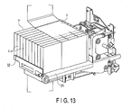
- a table 31 that supports the stacked bundle T' pressed out by the pressing member 1 includes a movable guide plate 32 that arranges the longitudinal direction of the stacked bundle T' as shown in FIG. 13 .
- the guide plate 32 has moved to a position that is slightly away from the stacked bundle T' along the longitudinal direction of the bills in advance, thereby preventing the stacked bundle T' from collapsing.
- the stacked bundle T' is pressed by the pressing member 1, and the right end thereof in the figure is pressed by the binding film f, thereby being compressed in its stacking direction.
- the compressing force of the stacked bundle T' can be changed by changing the brake forces given to the film rolls 21 and 22 by the brake rollers 24H and 24L.
- the compressing force of the stacked bundle T' can also be added by a tension mechanism, not by the brake rollers 24H and 24L.
- a tension mechanism not by the brake rollers 24H and 24L.
- the binding film f wound around the upper and lower surfaces of the stacked bundle T' is slightly folded along the back end of the stacked bundle T' in the moving direction.
- the back end of the stacked bundle T' in the moving direction is pressed near its corners by the two grippers 3 and 4.
- the stacked bundle T' is compressed in the stacking direction as described above, and thus the binding film f fastens the stacked bundle T'.
- the pressing member 1 being present between the upper gripper 3 and the lower gripper 4 in this state, needs to retreat to avoid interfering with the grippers 3 and 4, but the stacked bundle T' is being pulled in a direction of being pressed back by the film. Thus, a means for pressing the stacked bundle T' is necessary before retracting the pressing member 1.
- the pressing member 1 comprises a sliding portion 3a (a movable pressing member) and a fixed portion la (a fixed pressing member).
- the sliding portion 3a slides in a vertical direction.
- the upper gripper 3 operates to descend, the upper gripper 3 is inserted into the side surface of the stacked bundle T' while pressing down the portion 1a. Accordingly, there is no concern that the stacked bundle T' may collapse due to the winding of the binding film f.
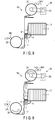
- the lower surface of the stacked bundle T' comes into a state of FIG. 6 as the lower gripper 4 rises.
- the pressing member 1 retreats in this state, since the upper and lower edges of the stacked bundle T' are caught by the upper gripper 3 and the lower gripper 4, the pressing member 1 can retreat without the stacked bundle T' moving back.
- the sliding portion 3a returns to an original state by a spring upon becoming a state of not being pressed by the upper gripper 3. It is possible to have an appropriate catching amount by making the descending amount of the upper gripper 3 variable, depending on the height of the stacked bundle T' in accordance with the kind of bills. After the pressing member 1 has completely retreated, the upper gripper 3 further descends while pressing the back end of the stacked bundle T' until abutting the lower gripper 4, and pinches the binding film f in a stacked state.
- the brake roller 24H is separated from the outer peripheral surface 21a of the upper film roll 21, and the brake roller 24L is separated from the outer peripheral surface 22a of the lower film roll 22, and the tension of the binding film f is loosened once.
- the upper film roll 21 is wound slightly by a weak force to give a weak tension to the binding film f.
- the heater blade 7 is caused to descend to be separated from the upper gripper 3, and the welded portion is cooled so as to be securely bound.
- the downstream blade 6 is caused to descend to be separated from the upper gripper 3. Thereby, a bunch T is formed.
- the upper gripper 3 is caused to rise in an arrow direction in the figure to wait for a stacked bundle T' to bind next.
- the upper gripper 3 is caused to descend so as to be pressed against the lower gripper 4, and the welded position of the binding film f is thus close to the lower gripper 4.
- the upper film roll 21 is slightly rolled to move the welded portion f' of the binding film f to the upper film roll 21 side.
- the stacked bundle T' is pressed in the stacking direction by the pressing member 1, the stacked bundle T' is pressed against the binding film f, and the binding film f is folded on the back end side of the stacked bundle T' to support the back end. Accordingly, the binding film f can be wound around the stacked bundle T' firmly, and a plurality of stacked bills can be bound neatly.
- the members (corresponding to the pressing member 1 and the upper and lower grippers 3 and 4 of the present embodiment) that compress the stacked bundle T' for binding are arranged outside the binding film f, and thus would never be obstructive to the binding of the binding film f.
- the binding film f having substantially the same width as that of the stacked bundle T' can be wound around the stacked bundle T', and the bound state of the bunch T can be stabilized significantly.
- the pressing member 1 and the upper gripper 3 can be arranged in a nested manner, and thus the end portion of the stacked bundle T' in a state of being pressed by the pressing surface la of the pressing member 1 can be pressed by the plate-like protrusion 3a of the upper gripper 3, thereby preventing the stacked bundle T' from disturbing its stacked orientation when winding the binding film f.
- the upper gripper 3 in a state where the back end corner portion of the stacked bundle T' in the moving direction is pressed by the lower gripper 4, when the upper gripper 3 is moved toward the lower gripper 4, the upper gripper 3 can be slid while the end portions of a plurality of plate-like protrusions 3a are pressed against the stacked bundle T', and the binding film f can be wound while being pressed on the back end surface of the stacked bundle T'.
- a plurality of plate-like protrusions 3a include end portions provided to extend in the moving direction of the upper gripper 3, a contact area with the stacked bundle T' can be reduced and the movement of the upper gripper 3 can be made smooth.
- a movable range of the upper gripper 3 is made larger than the lower gripper 4, and the moving distance of the upstream blade 5, the downstream blade 6, and the heater blade 7 of the lower gripper 4 is made short, these three blades 5, 6, and 7 can be moved independently by using the cam mechanism.
- the actuator that moves each of the blades 5, 6, and 7 of the lower gripper 4 can be simplified, and minute motion can be realized.
- the binding film f in a state where the binding film f is pinched and bound between the upstream blade 5 and the downstream blade 6 of the lower gripper 4 and the upper gripper 3, the binding film f is welded by the heater blade 7 arranged between these two blades 5 and 6, and thus the binding film f can be securely welded at the welded portion f'.
- the upstream blade 5 on the film rolls 21 and 22 side is separated from the upper gripper 3, so that the binding film f is cut at the welded portion f', and thus the binding film f can be cut cleanly.
- the heater blade 7 is separated from the upper gripper 3, and thus the welded portion f' can be sufficiently cooled and securely bound.
- the present invention is applied to an apparatus that binds a plurality of bills; however, not being limited thereto, the present invention can be applied to an apparatus that binds paper sheets, such as various tickets and cards.
Landscapes
- Engineering & Computer Science (AREA)
- Mechanical Engineering (AREA)
- Physics & Mathematics (AREA)
- General Physics & Mathematics (AREA)
- Basic Packing Technique (AREA)
- Packaging Of Special Articles (AREA)
- Containers And Plastic Fillers For Packaging (AREA)
Description
- Embodiments described herein relate generally to a paper sheet binding apparatus that stacks and binds a plurality of paper sheets.
- Conventionally, as a paper sheet binding apparatus that stacks and binds a plurality of paper sheets, for example, an apparatus that stacks and binds a plurality of paper bills by a belt-shape film is known. This apparatus is configured to, for example, move a plurality of bills, which are stacked in a vertical direction, to a horizontal direction while being compressed in the vertical direction, press the bills between conveyor belts while winding around the bills a film fed ahead of the moving direction, and weld the film together behind the bills to bind them.
- However, in the aforementioned conventional apparatus, the stacking direction and the pressing direction of the bills are different, and thus there is a possibility that a form of the bills may collapse when the stacked bills are pressed between the conveyor belts, and the bills cannot be bound neatly.
- Therefore, there is a demand for a paper sheet binding apparatus which is capable of binding a plurality of stacked paper sheets neatly.
-
US3720040 (A ) discloses a parcelling apparatus for installation downstream of a stacking device of paper or plastics bag-making machinery that delivers stacks of flattened bags. The parcelling apparatus has means for engaging successive stacks arriving lengthwise from the stacking device and for swinging the stacks sideways through 90° in alternately opposite directions, means for feeding the swung stacks to and depositing them side-on onto a table which extends normal to the feeding direction, and a reciprocatable pushing device which is adapted to move the deposited stacks to a parcelling station where a plurality of the stacks are juxtaposed preparatory to being packaged. -
CN104309843 (A ) discloses a bill bundle sorting, shaping and binding device and a method for pre-shaping a plastic package of the bill bundle. The bill bundle sorting, shaping and binding device comprises a rack, a bill bundle conveying mechanism arranged on the rack, a film conveying mechanism and a sealing and cutting mechanism, wherein a pressurization push plate, unidirectional baffles and a boosting plate are arranged on a horizontally arranged platform from left to right. The bill bundle conveying mechanism is arranged above the platform and conveys the bill bundle onto the platform and before the boosting plate by virtue of a sliding rail. The boosting plate and the pressurization push plate are respectively matched and provided with linear driving mechanisms. Automatic reset mechanisms which are forced to rotate and formed from the unidirectional baffles by virtue of location of a rotating shaft and limiting of a limited post are symmetrically arranged on the two sides of the platform. -
-
FIG. 1 is a block diagram of a bill processing apparatus according to an embodiment. -
FIG. 2 is a schematic view showing a stacking mechanism of a binding processor incorporated into the bill processing apparatus ofFIG. 1 . -
FIG. 3 is a schematic view showing a binding mechanism of the binding processor incorporated into the bill processing apparatus ofFIG. 1 . -
FIGS. 4-11 are diagrams for explaining an operation of the binding mechanism ofFIG. 3 . -
FIG. 12 is a diagram for explaining operations of a pressing member and an upper gripper of the binding mechanism ofFIG. 3 . -
FIG. 13 is a perspective view showing the stacking mechanism ofFIG. 2 . - According to one embodiment, the paper sheet binding apparatus according to claim 1 is provided.
- Various Embodiments will be described hereinafter with reference to the accompanying drawings.
-
FIG. 1 is a block diagram of abill processing apparatus 100 according to an embodiment. - The
bill processing apparatus 100 includes achassis 100a, and includes aconveyance path 101 extending substantially horizontally across an upper portion of thechassis 100a. Thisconveyance path 101 separates bills (paper sheets) (not shown), which were received from afeed device 110 provided (on the right side in the figure) separately from thebill processing apparatus 100, one by one, and conveys the bills. Thefeed device 110 sends a plurality of bills in a stacked state to theconveyance path 101 one by one. - The
bill processing apparatus 100 includes twodetection devices conveyance path 101. In the present embodiment, twodetection devices 102 facing with each other are provided on both sides (an upper side and a lower side in the figure) of theconveyance path 101. The number of thedetection devices 102 may be set appropriately. Each of thedetection devices 102 is located at a center of theconveyance path 101. The twodetection devices 102 detect characteristics of both sides of the bills conveyed through theconveyance path 101. - The
detection device 102 may be, for example, a device using an ultraviolet light for detecting stains of bills, or a device using fluorescence and/or phosphorescence. In any case, thedetection device 102 detects real or fake bills, stains or damage, denomination, and other bill characteristics. - The bills that have passed through the
detection devices 102 are respectively allocated to predeterminedprocessors 103 to 106 through theconveyance path 101 based on the detected characteristics. Provided on theconveyance path 101 is a gate (not shown) and a conveyance guide (not shown) for conveying the bills to desired destinations. - A
processor 104 provided furthest upstream of theconveyance path 101 is areject stacking unit 104 that stacks bills suspected of having been counterfeited, bills determined to need reexamination, or bills output by two in a stacked manner and that could not be separated, and skewed bills output in an offset manner that exceeds a detectable limit. - A
processor 105 on the downstream side of thereject stacking unit 104 is ashredder 105 that counts and shreds bills that are authentic bills but have a high degree of stains and damage, and were thus determined as not being reusable. - In addition, two
processors shredder 105 are bindingprocessors binding processors 106 may be set appropriately, and the processor may be provided for every denomination, and multiple processors may be provided for one denomination. - Furthermore, a
processor 103 provided at an end of theconveyance path 101 is anend stacking unit 103 that stacks bills that were not assigned to any of theprocessors - The
bill processing apparatus 100 includes acontrol device 108 that controls an operation of each unit of thebill processing apparatus 100. Thecontrol device 108, for example, controls a detecting operation in thedetection device 102, controls various operations in each of theprocessors 103 to 106, such as stacking, shredding, and binding, and designates destinations of the bills to be conveyed through theconveyance path 101. Thecontrol device 108 may be a single processing device, or may include multiple processors. - Moreover, the
bill processing apparatus 100 includes a storage medium (for example, memory or storage device) that stores a computer code used for controlling thecontrol device 108, and the like. Thecontrol device 108 reads out programs from such an accessible memory to execute various steps. Thecontrol device 108 includes a dedicated generic computer, a computer processor such as RISC or CISC, a digital signal processor (DSP), and the like. - The aforementioned
binding processors 106 respectively include device configurations for bundling a plurality of bills into an easy-to-handle size. For example, in the present embodiment, eachbinding processor 106 includes a sealing mechanism (not shown) that seals a predetermined number of bills (100 bills in the present embodiment) by a small belt. In addition, eachbinding processor 106 includes a binding mechanism 10 (see, for example,FIG. 3 ) that stacks and binds a plurality (10 bundles in the present embodiment) of bundles of bills that were sealed by the sealing mechanism. - The
binding mechanism 10 is an example of the paper sheet binding apparatus of the present invention. The sealing mechanism not shown here is not an essential configuration to the present invention, and loose bills may be stacked by a predetermined number (1000 in the present embodiment) to be bound by thebinding mechanism 10. Note that in the present embodiment, eachbinding mechanism 10 produces a bunch T of 1000 bills by stacking and bundling 10 bundles t, but the number of bills included in one bundle and the number of bundles t included in one bunch may be changed appropriately. - As shown in
FIG. 2 , astacking mechanism 9 of the bundles t is disposed on the upstream side of thebinding mechanism 10, and receives and stacks the bundles t ejected from the sealing mechanism (not shown) on the pressing member 1 in order. Upon completion of the stacking, thestacking mechanism 9 is rotated by a rotating mechanism (not shown) in an arrow direction to a position at which the stacked upper-end bundle t neighbors the binding film f, and the stacked bundle T' is rotationally moved. In this state (a state shown by dashed lines inFIG. 2 ), each bundle t included in the stacked bundle T' becomes a standing state in which its short-length direction is oriented in a vertical direction, and will be in a state in which a bottom end is supported by a supporting member (not shown). - As shown in
FIG. 3 , thebinding mechanism 10 includes the pressing member 1 that presses 10 bundles t in a stacking direction (the right direction in the figure) to move this stacked bundle T' (the object to be bound) in the right direction in the figure. The pressing member 1 includes a flat pressing surface la to be in contact with a bundle t (the bundle at the left end in the figure) present at an end in the stacking direction of the stacked bundle T', and is moved to a direction (the right direction in the figure) to press the stacked bundle T' by a moving mechanism (not shown). - In addition, the
binding mechanism 10 includes a feed device 20 (a feed unit) for feeding a belt-shape binding film f (a binding belt) ahead of the moving direction of the stacked bundle T'. Thefeed device 20 feeds the binding film f in a direction orthogonal to the stacking direction of the stacked bundle T' on the side opposite to the pressing member 1 relative to the stacked bundle T'. In the present embodiment, the binding film f is wound along the short-length direction of the stacked bundle T', and thus thefeed device 20 feeds the binding film f along the vertical direction. - Specifically, the
feed device 20 includes two upper andlower film rolls motor 23 is connected to arotation axis 21b of theupper film roll 21 via a belt, and a predetermined torque is given to therotation axis 21b in a direction of winding the binding film f. - In addition, the
feed device 20 includes a plurality ofguide rollers guide rollers guide roller 25a is a tension roller that gives a predetermined tension to the binding film f. - The two film rolls 21 and 22 have
brake rollers brake rollers peripheral surfaces 21a and 22a of the film rolls 21 and 22 so as to function to apply brakes to the rotation of the film rolls 21 and 22. - For example, one
brake roller 24H is selectively moved to a position where it is pressed against the outerperipheral surface 21a of theupper film roll 21, and to a position where it is separated from the outerperipheral surface 21a, by an actuator, such as a solenoid. In addition, anotherbrake roller 24L is selectively moved to a position where it is pressed against the outer peripheral surface 22a of thelower film roll 22, and to a position where it is separated from the outer peripheral surface 22a, by an actuator, such as a solenoid. - The binding
mechanism 10 also includes anupper gripper 3 and alower gripper 4. The twogrippers - The stacked bundle T' is pressed by the pressing member 1, and is pressed between the
upper gripper 3 and thelower gripper 4 while pressing the binding film f fed by thefeed device 20. Thereby, in a state of pressing the stacked bundle T' in the stacking direction, the binding film f is gradually wound around the stacked bundle T'. - The
upper gripper 3 and thelower gripper 4 function so as to fold the binding film f along the back end in the moving direction of the stacked bundle T' around which the binding film f is wound. At this time, the twogrippers upper gripper 3 and thelower gripper 4 function as press members that press the back end of the stacked bundle T' so that the stacked bundle T' pressed in the stacking direction does not move in the reverse direction. Theupper gripper 3 and thelower gripper 4 are capable of moving in the vertical direction, in which they separate from and contact with each other, by an actuator (not shown). - The
upper gripper 3, at least its lower surface side facing thelower gripper 4, is made of rubber. Thelower gripper 4 includes twopressing blades upper gripper 3. In explanations below, thepressing blade 5 on the upstream side along the moving direction of the stacked bundle T' may be referred to as theupstream blade 5, and thepressing blade 6 on the downstream side along the moving direction may be referred to as thedownstream blade 6. The twopressing blades - Furthermore, a
heater blade 7 is provided projectably/retractably between the twopressing blades upper gripper 3, by an actuator (not shown), such as a cam mechanism. Theheater blade 7 is connected to a heat source (not shown), and functions as a welding and cutting unit that welds (binds) and cuts the binding films f pressed by the twopressing blades upper gripper 3. - A table 31 that supports the stacked bundle T' pressed out by the pressing member 1 includes a
movable guide plate 32 that arranges the longitudinal direction of the stacked bundle T' as shown inFIG. 13 . When the stacked bundle T' is pressed out by the pressing member 1, there is a possibility that the stacked bundle T' may deform into a fan form due to the compressing force being applied, and the bound form may collapse. Theguide plate 32 has moved to a position that is slightly away from the stacked bundle T' along the longitudinal direction of the bills in advance, thereby preventing the stacked bundle T' from collapsing. - An operation of the aforementioned
binding mechanism 10 will now be described with reference toFIGS. 3 to 12 . - From the state shown in
FIG. 3 , as the pressing member 1 is moved in arrow F direction as shown inFIG. 4 and the stacked bundle T' is pressed between the twogrippers - At this time, brake forces to suppress rotation are given to the
upper film roll 21 and thelower film roll 22 of thefeed device 20 respectively by thebrake rollers - Thus, the stacked bundle T', the left end thereof in the figure, is pressed by the pressing member 1, and the right end thereof in the figure is pressed by the binding film f, thereby being compressed in its stacking direction. At this time, the compressing force of the stacked bundle T' can be changed by changing the brake forces given to the film rolls 21 and 22 by the
brake rollers - The compressing force of the stacked bundle T' can also be added by a tension mechanism, not by the
brake rollers tension roller 25a, it is possible to energize by a spring, detect a position of a tensioner by a sensor (not shown), and obtain a compressing force by driving themotor 23 by a signal of the sensor. In addition, it is possible to switch between a weak tension for performing a film fusion cutting to be described later and a strong tension for applying the compressing force by providing a plurality of sensors and two kinds of strong and weak energizing springs. - Then, as shown in
FIG. 5 , when the stacked bundle T' moves to a position where the back end of the stacked bundle T' in the moving direction passes the two upper andlower grippers FIG. 6 , the twogrippers - Thus, the binding film f wound around the upper and lower surfaces of the stacked bundle T' is slightly folded along the back end of the stacked bundle T' in the moving direction. In addition, by this, the back end of the stacked bundle T' in the moving direction is pressed near its corners by the two
grippers - In
FIG. 5 , the pressing member 1, being present between theupper gripper 3 and thelower gripper 4 in this state, needs to retreat to avoid interfering with thegrippers - As shown in
FIG. 12 , according to the invention, the pressing member 1 comprises a slidingportion 3a (a movable pressing member) and a fixed portion la (a fixed pressing member). The slidingportion 3a slides in a vertical direction. When theupper gripper 3 operates to descend, theupper gripper 3 is inserted into the side surface of the stacked bundle T' while pressing down theportion 1a. Accordingly, there is no concern that the stacked bundle T' may collapse due to the winding of the binding film f. - The lower surface of the stacked bundle T' comes into a state of
FIG. 6 as thelower gripper 4 rises. When the pressing member 1 retreats in this state, since the upper and lower edges of the stacked bundle T' are caught by theupper gripper 3 and thelower gripper 4, the pressing member 1 can retreat without the stacked bundle T' moving back. - The sliding
portion 3a returns to an original state by a spring upon becoming a state of not being pressed by theupper gripper 3. It is possible to have an appropriate catching amount by making the descending amount of theupper gripper 3 variable, depending on the height of the stacked bundle T' in accordance with the kind of bills. After the pressing member 1 has completely retreated, theupper gripper 3 further descends while pressing the back end of the stacked bundle T' until abutting thelower gripper 4, and pinches the binding film f in a stacked state. - In a state where the two upper and lower binding films f are pinched in a stacked state by the
upper gripper 3 and thelower gripper 4 as shown inFIG. 7 , theheater blade 7 is raised from between the twopressing blades upper gripper 3, as shown inFIG. 8 . At this time, the two binding films f are pinched between theupstream blade 5 and theupper gripper 3, and between thedownstream blade 6 and theupper gripper 3, and thus the two binding films f are welded between theupstream blade 5 and thedownstream blade 6 in a state where both sides of the welding position are securely held. - After that, as shown in
FIG. 9 , thebrake roller 24H is separated from the outerperipheral surface 21a of theupper film roll 21, and thebrake roller 24L is separated from the outer peripheral surface 22a of thelower film roll 22, and the tension of the binding film f is loosened once. Then, theupper film roll 21 is wound slightly by a weak force to give a weak tension to the binding film f. - From this state, as shown in
FIG. 10 , when theupstream blade 5 is caused to descend to be separated from theupper gripper 3, the binding films f on the film rolls 21 and 22 sides are pulled by a weak force, and are cut and separated at the welded position. In this state, the binding films f on the stacked bundle T' side are pinched and bound by thedownstream blade 6 and theupper gripper 3. - Thereafter, the
heater blade 7 is caused to descend to be separated from theupper gripper 3, and the welded portion is cooled so as to be securely bound. After both ends of the binding film f are bound as such, thedownstream blade 6 is caused to descend to be separated from theupper gripper 3. Thereby, a bunch T is formed. - Finally, as shown in
FIG. 11 , theupper gripper 3 is caused to rise in an arrow direction in the figure to wait for a stacked bundle T' to bind next. In the present embodiment, from the state shown inFIG. 6 , theupper gripper 3 is caused to descend so as to be pressed against thelower gripper 4, and the welded position of the binding film f is thus close to thelower gripper 4. Thus, in order to make the film consumption amount of theupper film roll 21 and thelower film roll 22 the same, theupper film roll 21 is slightly rolled to move the welded portion f' of the binding film f to theupper film roll 21 side. - As above, according to the present embodiment, the stacked bundle T' is pressed in the stacking direction by the pressing member 1, the stacked bundle T' is pressed against the binding film f, and the binding film f is folded on the back end side of the stacked bundle T' to support the back end. Accordingly, the binding film f can be wound around the stacked bundle T' firmly, and a plurality of stacked bills can be bound neatly.
- In addition, according to the present embodiment, the members (corresponding to the pressing member 1 and the upper and
lower grippers - According to the present embodiment, the pressing member 1 and the
upper gripper 3 can be arranged in a nested manner, and thus the end portion of the stacked bundle T' in a state of being pressed by the pressing surface la of the pressing member 1 can be pressed by the plate-like protrusion 3a of theupper gripper 3, thereby preventing the stacked bundle T' from disturbing its stacked orientation when winding the binding film f. - According to the present embodiment, in a state where the back end corner portion of the stacked bundle T' in the moving direction is pressed by the
lower gripper 4, when theupper gripper 3 is moved toward thelower gripper 4, theupper gripper 3 can be slid while the end portions of a plurality of plate-like protrusions 3a are pressed against the stacked bundle T', and the binding film f can be wound while being pressed on the back end surface of the stacked bundle T'. At this time, since a plurality of plate-like protrusions 3a include end portions provided to extend in the moving direction of theupper gripper 3, a contact area with the stacked bundle T' can be reduced and the movement of theupper gripper 3 can be made smooth. - According to the present embodiment, since a movable range of the
upper gripper 3 is made larger than thelower gripper 4, and the moving distance of theupstream blade 5, thedownstream blade 6, and theheater blade 7 of thelower gripper 4 is made short, these threeblades blades lower gripper 4 can be simplified, and minute motion can be realized. - According to the present embodiment, in a state where the binding film f is pinched and bound between the
upstream blade 5 and thedownstream blade 6 of thelower gripper 4 and theupper gripper 3, the binding film f is welded by theheater blade 7 arranged between these twoblades - According to the present embodiment, after welding the binding film f at the welded portion f', in a state where a weak tension is given to the binding film f, the
upstream blade 5 on the film rolls 21 and 22 side is separated from theupper gripper 3, so that the binding film f is cut at the welded portion f', and thus the binding film f can be cut cleanly. - Furthermore, according to the present embodiment, after cutting the binding film f at the welded portion f', in a state where the binding film f on the bunch T side is pinched and bound between the
downstream blade 6 and theupper gripper 3, theheater blade 7 is separated from theupper gripper 3, and thus the welded portion f' can be sufficiently cooled and securely bound. - While certain embodiments have been described, these embodiments have been presented by way of example only, and are not intended to limit the scope of the invention.
- For example, in the aforementioned embodiment, the case where the present invention is applied to an apparatus that binds a plurality of bills is explained; however, not being limited thereto, the present invention can be applied to an apparatus that binds paper sheets, such as various tickets and cards.
Claims (4)
- A paper sheet binding apparatus, comprising:a pressing member (1) that presses a stacked bundle (T') with a plurality of stacked paper sheets in a stacking direction of the paper sheets to move the stacked bundle (T') in the stacking direction;a feed unit (20) that feeds a binding belt (f) in a direction orthogonal to the stacking direction ahead of a moving direction of the stacked bundle (T');an upper gripper (3) and a lower gripper (4), the pressing member (1) being present between the upper gripper (3) and the lower gripper (4), the upper gripper (3) and the lower gripper (4) function as to fold the binding belt (f) along a back end in the moving direction of the stacked bundle (T') around which the binding belt (f) is wound, and function as press members that press the back end of the stacked bundle (T') so that the stacked bundle (T') pressed in the stacking direction does not move in the reverse direction; anda welding and cutting unit (7) that welds the folded binding belts (f) with each other and cuts the binding belts (f)characterized in thatthe pressing member (1) comprises a fixed portion (1a) and a sliding portion (3a) movable with respect to the fixed portion (1a), and the sliding portion (3a) is arranged so as to be pressed in the direction orthogonal to the stacking direction by the upper gripper (3) in a state of pressing the back end.
- The paper sheet binding apparatus of claim 1, wherein
the welding and cutting unit (7) is provided in the lower gripper (4). - The paper sheet binding apparatus of claim 2, wherein
the lower gripper (4) comprises two pressing blades (5,6) separately arranged along the binding belt and a heater blade (7) as the welding and cutting unit that welds the binding belts (f) with each other between the two pressing blades (5,6). - The paper sheet binding apparatus of claim 1, wherein
a supporting member (31) that supports the stacked bundle (T') is provided with a movable guide (32) configured to guide the stacked bundle (T') along the stacking direction.
Applications Claiming Priority (1)
| Application Number | Priority Date | Filing Date | Title |
|---|---|---|---|
| JP2016180437A JP2018043769A (en) | 2016-09-15 | 2016-09-15 | Paper sheet bundling device |
Publications (2)
| Publication Number | Publication Date |
|---|---|
| EP3296218A1 EP3296218A1 (en) | 2018-03-21 |
| EP3296218B1 true EP3296218B1 (en) | 2021-03-31 |
Family
ID=59914263
Family Applications (1)
| Application Number | Title | Priority Date | Filing Date |
|---|---|---|---|
| EP17188540.3A Active EP3296218B1 (en) | 2016-09-15 | 2017-08-30 | Paper sheet binding apparatus |
Country Status (4)
| Country | Link |
|---|---|
| US (1) | US20180072442A1 (en) |
| EP (1) | EP3296218B1 (en) |
| JP (1) | JP2018043769A (en) |
| RU (1) | RU2668325C1 (en) |
Families Citing this family (4)
| Publication number | Priority date | Publication date | Assignee | Title |
|---|---|---|---|---|
| CN111137516B (en) * | 2019-12-20 | 2021-12-28 | 浙江埃芮克环保科技有限公司 | Woven bag detection and waste removal production line and process thereof |
| CN112706969B (en) * | 2020-12-11 | 2022-06-10 | 绍兴市上虞区鑫鑫开关厂 | Packaging and storing electromechanical integrated equipment for silage products |
| CN118494846B (en) * | 2024-07-18 | 2024-11-22 | 苏州百狮腾电气有限公司 | Automatic bundling device for motor wiring harness |
| JP7705000B1 (en) * | 2025-04-04 | 2025-07-09 | 久米機電工業株式会社 | Belting means |
Family Cites Families (16)
| Publication number | Priority date | Publication date | Assignee | Title |
|---|---|---|---|---|
| US2741885A (en) * | 1952-12-08 | 1956-04-17 | Gen Mills Inc | Banding with thermoplastic |
| DE2018592C3 (en) * | 1970-04-17 | 1978-03-23 | Windmoeller & Hoelscher, 4540 Lengerich | Device for forming cuboid bag packages |
| DE2022577C3 (en) * | 1970-05-08 | 1980-03-13 | Kooperativa Foerbundet (Kf) Ekonomisk Foerening, Stockholm | Method and device for producing a weld seam on a film envelope placed under tension around a stack of packs |
| US3943024A (en) * | 1972-01-26 | 1976-03-09 | Sendor Bernard T | Paper welding apparatus for bookbinding machinery |
| WO1988009748A1 (en) * | 1987-06-10 | 1988-12-15 | Autefa Maschinenfabrik Gmbh | Process and device for packing balls |
| SE465818B (en) * | 1988-01-28 | 1991-11-04 | Wamac Ab | SET AND DEVICE FOR WRAPPING MAGAZINE PACKAGES IN PACKAGING MOVIES |
| US5187922A (en) * | 1992-04-08 | 1993-02-23 | Quad/Tech, Inc. | Apparatus and method for transferring signatures to a wrapping machine |
| RU2073626C1 (en) * | 1993-04-14 | 1997-02-20 | Николай Иванович Павликов | Method of wrapping piles of sheets |
| DE19719239A1 (en) * | 1997-05-07 | 1998-11-12 | Giesecke & Devrient Gmbh | Device for the automatic bundling of sheet material |
| RU2123462C1 (en) * | 1997-07-28 | 1998-12-20 | Открытое акционерное общество "Мехбанк" | Securities counterfoil wrapper |
| JP2010253870A (en) * | 2009-04-28 | 2010-11-11 | Sankyo:Kk | Method and device for binding paper sheet |
| CN104309843B (en) * | 2014-08-20 | 2016-03-30 | 河北汇金机电股份有限公司 | Banknote bundle sorting and shaping binding device and banknote bundle plastic sealing presetting method |
| EP3045398A1 (en) * | 2015-01-15 | 2016-07-20 | ATS-Tanner Banding Systems AG | Method for bending strips around objects and corresponding machines |
| US20160264271A1 (en) * | 2015-03-12 | 2016-09-15 | Qubiqa Esbjerg A/S | Packaging in foil with predefined subsections |
| US9747741B2 (en) * | 2015-03-18 | 2017-08-29 | Toshiba International Corporation | In-pocket currency bundler |
| JP6742702B2 (en) * | 2015-07-14 | 2020-08-19 | キヤノン株式会社 | Packaging body and packaging method |
-
2016
- 2016-09-15 JP JP2016180437A patent/JP2018043769A/en active Pending
-
2017
- 2017-08-30 EP EP17188540.3A patent/EP3296218B1/en active Active
- 2017-09-15 RU RU2017132276A patent/RU2668325C1/en active
- 2017-09-15 US US15/706,104 patent/US20180072442A1/en not_active Abandoned
Non-Patent Citations (1)
| Title |
|---|
| None * |
Also Published As
| Publication number | Publication date |
|---|---|
| EP3296218A1 (en) | 2018-03-21 |
| RU2668325C1 (en) | 2018-09-28 |
| JP2018043769A (en) | 2018-03-22 |
| US20180072442A1 (en) | 2018-03-15 |
Similar Documents
| Publication | Publication Date | Title |
|---|---|---|
| US4683708A (en) | Method and apparatus for wrapping printed sheets | |
| NL1008727C2 (en) | Method and device for crushing a product folded along a fold line. | |
| EP2197772B1 (en) | Winding device and assembly comprising a winding device | |
| JP2001524057A (en) | Automatic binding device for sheet materials | |
| US20070272788A1 (en) | Paper feeding device for a banding machine for logs of sheet material | |
| JP2008276751A (en) | Paper sheet processing system | |
| EP3296218A1 (en) | Paper sheet binding apparatus | |
| KR20200016377A (en) | Dungeon Conversion Device and Method | |
| JP2694193B2 (en) | Separator for bag making machine | |
| EP2636496A1 (en) | Web product cutting and screening machine and method | |
| US4311090A (en) | Method producing a bundle of paper sheets | |
| JP4108218B2 (en) | Saddle folding machine | |
| CN110203751A (en) | For to the device and method for continue according to the printed sheet sequentially printed processing | |
| ITMI992400A1 (en) | DEVICE TO ALIGN THE PIPE STRIPS | |
| AU2004200127A1 (en) | Process and apparatus for producing stacks of printed products provided with an additional sheet | |
| CN106553927A (en) | Sheet stacker and method for forming stacks of interleaved bales | |
| CN212023092U (en) | Moving platform for banding machine and banding device | |
| JP2025518089A (en) | Device for realizing at least two continuous strips of corrugated cardboard of different widths for packaging by successively joining together a plurality of corrugated cardboard sheets of different widths, respectively. | |
| RU2507132C2 (en) | Method and device for packaging portioned products in blank for package | |
| CN213648707U (en) | A kind of semi-automatic sheet material stacking and binding equipment | |
| US20150057140A1 (en) | Folding machine as combined knife and buckle folders | |
| JP7838761B2 (en) | Method for manufacturing packaged products and packaging apparatus | |
| CN112758751B (en) | Stacking device and distinguishing method | |
| CN223291196U (en) | Paper forming equipment | |
| KR20260005955A (en) | Bending module for converting machines |
Legal Events
| Date | Code | Title | Description |
|---|---|---|---|
| PUAI | Public reference made under article 153(3) epc to a published international application that has entered the european phase |
Free format text: ORIGINAL CODE: 0009012 |
|
| STAA | Information on the status of an ep patent application or granted ep patent |
Free format text: STATUS: REQUEST FOR EXAMINATION WAS MADE |
|
| 17P | Request for examination filed |
Effective date: 20170830 |
|
| AK | Designated contracting states |
Kind code of ref document: A1 Designated state(s): AL AT BE BG CH CY CZ DE DK EE ES FI FR GB GR HR HU IE IS IT LI LT LU LV MC MK MT NL NO PL PT RO RS SE SI SK SM TR |
|
| AX | Request for extension of the european patent |
Extension state: BA ME |
|
| STAA | Information on the status of an ep patent application or granted ep patent |
Free format text: STATUS: EXAMINATION IS IN PROGRESS |
|
| 17Q | First examination report despatched |
Effective date: 20190122 |
|
| GRAP | Despatch of communication of intention to grant a patent |
Free format text: ORIGINAL CODE: EPIDOSNIGR1 |
|
| STAA | Information on the status of an ep patent application or granted ep patent |
Free format text: STATUS: GRANT OF PATENT IS INTENDED |
|
| RIC1 | Information provided on ipc code assigned before grant |
Ipc: B29C 65/00 20060101ALI20200930BHEP Ipc: B65B 27/08 20060101AFI20200930BHEP Ipc: G07D 11/40 20190101ALI20200930BHEP Ipc: B65B 61/10 20060101ALI20200930BHEP Ipc: G07D 11/50 20190101ALI20200930BHEP Ipc: B65B 41/16 20060101ALI20200930BHEP Ipc: B65B 27/12 20060101ALI20200930BHEP Ipc: B65B 25/14 20060101ALI20200930BHEP Ipc: B65B 11/10 20060101ALI20200930BHEP Ipc: B65B 13/32 20060101ALI20200930BHEP Ipc: B65B 51/14 20060101ALI20200930BHEP Ipc: B65B 41/18 20060101ALI20200930BHEP Ipc: B29C 65/74 20060101ALI20200930BHEP Ipc: G07D 11/00 20190101ALI20200930BHEP Ipc: B65B 57/04 20060101ALI20200930BHEP Ipc: B65B 51/24 20060101ALI20200930BHEP Ipc: B65B 13/22 20060101ALI20200930BHEP |
|
| INTG | Intention to grant announced |
Effective date: 20201026 |
|
| GRAS | Grant fee paid |
Free format text: ORIGINAL CODE: EPIDOSNIGR3 |
|
| GRAA | (expected) grant |
Free format text: ORIGINAL CODE: 0009210 |
|
| STAA | Information on the status of an ep patent application or granted ep patent |
Free format text: STATUS: THE PATENT HAS BEEN GRANTED |
|
| AK | Designated contracting states |
Kind code of ref document: B1 Designated state(s): AL AT BE BG CH CY CZ DE DK EE ES FI FR GB GR HR HU IE IS IT LI LT LU LV MC MK MT NL NO PL PT RO RS SE SI SK SM TR |
|
| REG | Reference to a national code |
Ref country code: GB Ref legal event code: FG4D Ref country code: CH Ref legal event code: EP |
|
| REG | Reference to a national code |
Ref country code: DE Ref legal event code: R096 Ref document number: 602017035572 Country of ref document: DE Ref country code: AT Ref legal event code: REF Ref document number: 1376689 Country of ref document: AT Kind code of ref document: T Effective date: 20210415 |
|
| REG | Reference to a national code |
Ref country code: IE Ref legal event code: FG4D |
|
| REG | Reference to a national code |
Ref country code: LT Ref legal event code: MG9D |
|
| PG25 | Lapsed in a contracting state [announced via postgrant information from national office to epo] |
Ref country code: BG Free format text: LAPSE BECAUSE OF FAILURE TO SUBMIT A TRANSLATION OF THE DESCRIPTION OR TO PAY THE FEE WITHIN THE PRESCRIBED TIME-LIMIT Effective date: 20210630 Ref country code: NO Free format text: LAPSE BECAUSE OF FAILURE TO SUBMIT A TRANSLATION OF THE DESCRIPTION OR TO PAY THE FEE WITHIN THE PRESCRIBED TIME-LIMIT Effective date: 20210630 Ref country code: FI Free format text: LAPSE BECAUSE OF FAILURE TO SUBMIT A TRANSLATION OF THE DESCRIPTION OR TO PAY THE FEE WITHIN THE PRESCRIBED TIME-LIMIT Effective date: 20210331 Ref country code: HR Free format text: LAPSE BECAUSE OF FAILURE TO SUBMIT A TRANSLATION OF THE DESCRIPTION OR TO PAY THE FEE WITHIN THE PRESCRIBED TIME-LIMIT Effective date: 20210331 |
|
| PG25 | Lapsed in a contracting state [announced via postgrant information from national office to epo] |
Ref country code: SE Free format text: LAPSE BECAUSE OF FAILURE TO SUBMIT A TRANSLATION OF THE DESCRIPTION OR TO PAY THE FEE WITHIN THE PRESCRIBED TIME-LIMIT Effective date: 20210331 Ref country code: RS Free format text: LAPSE BECAUSE OF FAILURE TO SUBMIT A TRANSLATION OF THE DESCRIPTION OR TO PAY THE FEE WITHIN THE PRESCRIBED TIME-LIMIT Effective date: 20210331 Ref country code: LV Free format text: LAPSE BECAUSE OF FAILURE TO SUBMIT A TRANSLATION OF THE DESCRIPTION OR TO PAY THE FEE WITHIN THE PRESCRIBED TIME-LIMIT Effective date: 20210331 |
|
| REG | Reference to a national code |
Ref country code: NL Ref legal event code: MP Effective date: 20210331 |
|
| REG | Reference to a national code |
Ref country code: AT Ref legal event code: MK05 Ref document number: 1376689 Country of ref document: AT Kind code of ref document: T Effective date: 20210331 |
|
| PG25 | Lapsed in a contracting state [announced via postgrant information from national office to epo] |
Ref country code: AT Free format text: LAPSE BECAUSE OF FAILURE TO SUBMIT A TRANSLATION OF THE DESCRIPTION OR TO PAY THE FEE WITHIN THE PRESCRIBED TIME-LIMIT Effective date: 20210331 Ref country code: NL Free format text: LAPSE BECAUSE OF FAILURE TO SUBMIT A TRANSLATION OF THE DESCRIPTION OR TO PAY THE FEE WITHIN THE PRESCRIBED TIME-LIMIT Effective date: 20210331 Ref country code: SM Free format text: LAPSE BECAUSE OF FAILURE TO SUBMIT A TRANSLATION OF THE DESCRIPTION OR TO PAY THE FEE WITHIN THE PRESCRIBED TIME-LIMIT Effective date: 20210331 Ref country code: EE Free format text: LAPSE BECAUSE OF FAILURE TO SUBMIT A TRANSLATION OF THE DESCRIPTION OR TO PAY THE FEE WITHIN THE PRESCRIBED TIME-LIMIT Effective date: 20210331 Ref country code: CZ Free format text: LAPSE BECAUSE OF FAILURE TO SUBMIT A TRANSLATION OF THE DESCRIPTION OR TO PAY THE FEE WITHIN THE PRESCRIBED TIME-LIMIT Effective date: 20210331 Ref country code: LT Free format text: LAPSE BECAUSE OF FAILURE TO SUBMIT A TRANSLATION OF THE DESCRIPTION OR TO PAY THE FEE WITHIN THE PRESCRIBED TIME-LIMIT Effective date: 20210331 |
|
| PG25 | Lapsed in a contracting state [announced via postgrant information from national office to epo] |
Ref country code: PT Free format text: LAPSE BECAUSE OF FAILURE TO SUBMIT A TRANSLATION OF THE DESCRIPTION OR TO PAY THE FEE WITHIN THE PRESCRIBED TIME-LIMIT Effective date: 20210802 Ref country code: PL Free format text: LAPSE BECAUSE OF FAILURE TO SUBMIT A TRANSLATION OF THE DESCRIPTION OR TO PAY THE FEE WITHIN THE PRESCRIBED TIME-LIMIT Effective date: 20210331 Ref country code: RO Free format text: LAPSE BECAUSE OF FAILURE TO SUBMIT A TRANSLATION OF THE DESCRIPTION OR TO PAY THE FEE WITHIN THE PRESCRIBED TIME-LIMIT Effective date: 20210331 Ref country code: SK Free format text: LAPSE BECAUSE OF FAILURE TO SUBMIT A TRANSLATION OF THE DESCRIPTION OR TO PAY THE FEE WITHIN THE PRESCRIBED TIME-LIMIT Effective date: 20210331 Ref country code: IS Free format text: LAPSE BECAUSE OF FAILURE TO SUBMIT A TRANSLATION OF THE DESCRIPTION OR TO PAY THE FEE WITHIN THE PRESCRIBED TIME-LIMIT Effective date: 20210731 |
|
| REG | Reference to a national code |
Ref country code: DE Ref legal event code: R097 Ref document number: 602017035572 Country of ref document: DE |
|
| PG25 | Lapsed in a contracting state [announced via postgrant information from national office to epo] |
Ref country code: AL Free format text: LAPSE BECAUSE OF FAILURE TO SUBMIT A TRANSLATION OF THE DESCRIPTION OR TO PAY THE FEE WITHIN THE PRESCRIBED TIME-LIMIT Effective date: 20210331 Ref country code: DK Free format text: LAPSE BECAUSE OF FAILURE TO SUBMIT A TRANSLATION OF THE DESCRIPTION OR TO PAY THE FEE WITHIN THE PRESCRIBED TIME-LIMIT Effective date: 20210331 Ref country code: ES Free format text: LAPSE BECAUSE OF FAILURE TO SUBMIT A TRANSLATION OF THE DESCRIPTION OR TO PAY THE FEE WITHIN THE PRESCRIBED TIME-LIMIT Effective date: 20210331 |
|
| PLBE | No opposition filed within time limit |
Free format text: ORIGINAL CODE: 0009261 |
|
| STAA | Information on the status of an ep patent application or granted ep patent |
Free format text: STATUS: NO OPPOSITION FILED WITHIN TIME LIMIT |
|
| 26N | No opposition filed |
Effective date: 20220104 |
|
| REG | Reference to a national code |
Ref country code: CH Ref legal event code: PL |
|
| PG25 | Lapsed in a contracting state [announced via postgrant information from national office to epo] |
Ref country code: MC Free format text: LAPSE BECAUSE OF FAILURE TO SUBMIT A TRANSLATION OF THE DESCRIPTION OR TO PAY THE FEE WITHIN THE PRESCRIBED TIME-LIMIT Effective date: 20210331 |
|
| REG | Reference to a national code |
Ref country code: BE Ref legal event code: MM Effective date: 20210831 |
|
| PG25 | Lapsed in a contracting state [announced via postgrant information from national office to epo] |
Ref country code: LI Free format text: LAPSE BECAUSE OF NON-PAYMENT OF DUE FEES Effective date: 20210831 Ref country code: CH Free format text: LAPSE BECAUSE OF NON-PAYMENT OF DUE FEES Effective date: 20210831 |
|
| PG25 | Lapsed in a contracting state [announced via postgrant information from national office to epo] |
Ref country code: IS Free format text: LAPSE BECAUSE OF FAILURE TO SUBMIT A TRANSLATION OF THE DESCRIPTION OR TO PAY THE FEE WITHIN THE PRESCRIBED TIME-LIMIT Effective date: 20210731 Ref country code: LU Free format text: LAPSE BECAUSE OF NON-PAYMENT OF DUE FEES Effective date: 20210830 |
|
| PG25 | Lapsed in a contracting state [announced via postgrant information from national office to epo] |
Ref country code: IT Free format text: LAPSE BECAUSE OF FAILURE TO SUBMIT A TRANSLATION OF THE DESCRIPTION OR TO PAY THE FEE WITHIN THE PRESCRIBED TIME-LIMIT Effective date: 20210331 Ref country code: IE Free format text: LAPSE BECAUSE OF NON-PAYMENT OF DUE FEES Effective date: 20210830 Ref country code: FR Free format text: LAPSE BECAUSE OF NON-PAYMENT OF DUE FEES Effective date: 20210831 Ref country code: BE Free format text: LAPSE BECAUSE OF NON-PAYMENT OF DUE FEES Effective date: 20210831 |
|
| PG25 | Lapsed in a contracting state [announced via postgrant information from national office to epo] |
Ref country code: HU Free format text: LAPSE BECAUSE OF FAILURE TO SUBMIT A TRANSLATION OF THE DESCRIPTION OR TO PAY THE FEE WITHIN THE PRESCRIBED TIME-LIMIT; INVALID AB INITIO Effective date: 20170830 |
|
| PG25 | Lapsed in a contracting state [announced via postgrant information from national office to epo] |
Ref country code: CY Free format text: LAPSE BECAUSE OF FAILURE TO SUBMIT A TRANSLATION OF THE DESCRIPTION OR TO PAY THE FEE WITHIN THE PRESCRIBED TIME-LIMIT Effective date: 20210331 |
|
| PG25 | Lapsed in a contracting state [announced via postgrant information from national office to epo] |
Ref country code: GR Free format text: LAPSE BECAUSE OF FAILURE TO SUBMIT A TRANSLATION OF THE DESCRIPTION OR TO PAY THE FEE WITHIN THE PRESCRIBED TIME-LIMIT Effective date: 20210331 |
|
| PG25 | Lapsed in a contracting state [announced via postgrant information from national office to epo] |
Ref country code: MK Free format text: LAPSE BECAUSE OF FAILURE TO SUBMIT A TRANSLATION OF THE DESCRIPTION OR TO PAY THE FEE WITHIN THE PRESCRIBED TIME-LIMIT Effective date: 20210331 |
|
| PG25 | Lapsed in a contracting state [announced via postgrant information from national office to epo] |
Ref country code: MT Free format text: LAPSE BECAUSE OF FAILURE TO SUBMIT A TRANSLATION OF THE DESCRIPTION OR TO PAY THE FEE WITHIN THE PRESCRIBED TIME-LIMIT Effective date: 20210331 |
|
| REG | Reference to a national code |
Ref country code: DE Ref legal event code: R081 Ref document number: 602017035572 Country of ref document: DE Owner name: KABUSHIKI KAISHA TOSHIBA, JP Free format text: FORMER OWNERS: KABUSHIKI KAISHA TOSHIBA, TOKYO, JP; TOSHIBA INFRASTRUCTURE SYSTEMS & SOLUTIONS CORPORATION, KAWASAKI-SHI, KANAGAWA, JP |
|
| PGFP | Annual fee paid to national office [announced via postgrant information from national office to epo] |
Ref country code: DE Payment date: 20250702 Year of fee payment: 9 |
|
| PGFP | Annual fee paid to national office [announced via postgrant information from national office to epo] |
Ref country code: GB Payment date: 20250703 Year of fee payment: 9 |
|
| REG | Reference to a national code |
Ref country code: GB Ref legal event code: 732E Free format text: REGISTERED BETWEEN 20251002 AND 20251008 |
|
| PG25 | Lapsed in a contracting state [announced via postgrant information from national office to epo] |
Ref country code: TR Free format text: LAPSE BECAUSE OF FAILURE TO SUBMIT A TRANSLATION OF THE DESCRIPTION OR TO PAY THE FEE WITHIN THE PRESCRIBED TIME-LIMIT Effective date: 20210331 |