EP3296049A1 - Electrical machining device and method, hybrid machining system and method - Google Patents
Electrical machining device and method, hybrid machining system and method Download PDFInfo
- Publication number
- EP3296049A1 EP3296049A1 EP17189331.6A EP17189331A EP3296049A1 EP 3296049 A1 EP3296049 A1 EP 3296049A1 EP 17189331 A EP17189331 A EP 17189331A EP 3296049 A1 EP3296049 A1 EP 3296049A1
- Authority
- EP
- European Patent Office
- Prior art keywords
- discharge current
- electrode
- feedrate
- workpiece
- acceleration
- Prior art date
- Legal status (The legal status is an assumption and is not a legal conclusion. Google has not performed a legal analysis and makes no representation as to the accuracy of the status listed.)
- Pending
Links
Images


Classifications
-
- B—PERFORMING OPERATIONS; TRANSPORTING
- B23—MACHINE TOOLS; METAL-WORKING NOT OTHERWISE PROVIDED FOR
- B23H—WORKING OF METAL BY THE ACTION OF A HIGH CONCENTRATION OF ELECTRIC CURRENT ON A WORKPIECE USING AN ELECTRODE WHICH TAKES THE PLACE OF A TOOL; SUCH WORKING COMBINED WITH OTHER FORMS OF WORKING OF METAL
- B23H1/00—Electrical discharge machining, i.e. removing metal with a series of rapidly recurring electrical discharges between an electrode and a workpiece in the presence of a fluid dielectric
- B23H1/02—Electric circuits specially adapted therefor, e.g. power supply, control, preventing short circuits or other abnormal discharges
- B23H1/024—Detection of, and response to, abnormal gap conditions, e.g. short circuits
-
- B—PERFORMING OPERATIONS; TRANSPORTING
- B23—MACHINE TOOLS; METAL-WORKING NOT OTHERWISE PROVIDED FOR
- B23H—WORKING OF METAL BY THE ACTION OF A HIGH CONCENTRATION OF ELECTRIC CURRENT ON A WORKPIECE USING AN ELECTRODE WHICH TAKES THE PLACE OF A TOOL; SUCH WORKING COMBINED WITH OTHER FORMS OF WORKING OF METAL
- B23H7/00—Processes or apparatus applicable to both electrical discharge machining and electrochemical machining
- B23H7/26—Apparatus for moving or positioning electrode relatively to workpiece; Mounting of electrode
-
- B—PERFORMING OPERATIONS; TRANSPORTING
- B23—MACHINE TOOLS; METAL-WORKING NOT OTHERWISE PROVIDED FOR
- B23H—WORKING OF METAL BY THE ACTION OF A HIGH CONCENTRATION OF ELECTRIC CURRENT ON A WORKPIECE USING AN ELECTRODE WHICH TAKES THE PLACE OF A TOOL; SUCH WORKING COMBINED WITH OTHER FORMS OF WORKING OF METAL
- B23H1/00—Electrical discharge machining, i.e. removing metal with a series of rapidly recurring electrical discharges between an electrode and a workpiece in the presence of a fluid dielectric
- B23H1/04—Electrodes specially adapted therefor or their manufacture
-
- B—PERFORMING OPERATIONS; TRANSPORTING
- B23—MACHINE TOOLS; METAL-WORKING NOT OTHERWISE PROVIDED FOR
- B23H—WORKING OF METAL BY THE ACTION OF A HIGH CONCENTRATION OF ELECTRIC CURRENT ON A WORKPIECE USING AN ELECTRODE WHICH TAKES THE PLACE OF A TOOL; SUCH WORKING COMBINED WITH OTHER FORMS OF WORKING OF METAL
- B23H1/00—Electrical discharge machining, i.e. removing metal with a series of rapidly recurring electrical discharges between an electrode and a workpiece in the presence of a fluid dielectric
- B23H1/02—Electric circuits specially adapted therefor, e.g. power supply, control, preventing short circuits or other abnormal discharges
- B23H1/026—Power supply protection, e.g. detection of power switch breakdown
-
- B—PERFORMING OPERATIONS; TRANSPORTING
- B23—MACHINE TOOLS; METAL-WORKING NOT OTHERWISE PROVIDED FOR
- B23H—WORKING OF METAL BY THE ACTION OF A HIGH CONCENTRATION OF ELECTRIC CURRENT ON A WORKPIECE USING AN ELECTRODE WHICH TAKES THE PLACE OF A TOOL; SUCH WORKING COMBINED WITH OTHER FORMS OF WORKING OF METAL
- B23H7/00—Processes or apparatus applicable to both electrical discharge machining and electrochemical machining
- B23H7/26—Apparatus for moving or positioning electrode relatively to workpiece; Mounting of electrode
- B23H7/30—Moving electrode in the feed direction
-
- B—PERFORMING OPERATIONS; TRANSPORTING
- B23—MACHINE TOOLS; METAL-WORKING NOT OTHERWISE PROVIDED FOR
- B23Q—DETAILS, COMPONENTS, OR ACCESSORIES FOR MACHINE TOOLS, e.g. ARRANGEMENTS FOR COPYING OR CONTROLLING; MACHINE TOOLS IN GENERAL CHARACTERISED BY THE CONSTRUCTION OF PARTICULAR DETAILS OR COMPONENTS; COMBINATIONS OR ASSOCIATIONS OF METAL-WORKING MACHINES, NOT DIRECTED TO A PARTICULAR RESULT
- B23Q5/00—Driving or feeding mechanisms; Control arrangements therefor
- B23Q5/22—Feeding members carrying tools or work
- B23Q5/28—Electric drives
-
- B—PERFORMING OPERATIONS; TRANSPORTING
- B65—CONVEYING; PACKING; STORING; HANDLING THIN OR FILAMENTARY MATERIAL
- B65H—HANDLING THIN OR FILAMENTARY MATERIAL, e.g. SHEETS, WEBS, CABLES
- B65H35/00—Delivering articles from cutting or line-perforating machines; Article or web delivery apparatus incorporating cutting or line-perforating devices, e.g. adhesive tape dispensers
-
- B—PERFORMING OPERATIONS; TRANSPORTING
- B23—MACHINE TOOLS; METAL-WORKING NOT OTHERWISE PROVIDED FOR
- B23H—WORKING OF METAL BY THE ACTION OF A HIGH CONCENTRATION OF ELECTRIC CURRENT ON A WORKPIECE USING AN ELECTRODE WHICH TAKES THE PLACE OF A TOOL; SUCH WORKING COMBINED WITH OTHER FORMS OF WORKING OF METAL
- B23H2500/00—Holding and positioning of tool electrodes
-
- B—PERFORMING OPERATIONS; TRANSPORTING
- B23—MACHINE TOOLS; METAL-WORKING NOT OTHERWISE PROVIDED FOR
- B23H—WORKING OF METAL BY THE ACTION OF A HIGH CONCENTRATION OF ELECTRIC CURRENT ON A WORKPIECE USING AN ELECTRODE WHICH TAKES THE PLACE OF A TOOL; SUCH WORKING COMBINED WITH OTHER FORMS OF WORKING OF METAL
- B23H5/00—Combined machining
- B23H5/04—Electrical discharge machining combined with mechanical working
-
- B—PERFORMING OPERATIONS; TRANSPORTING
- B23—MACHINE TOOLS; METAL-WORKING NOT OTHERWISE PROVIDED FOR
- B23H—WORKING OF METAL BY THE ACTION OF A HIGH CONCENTRATION OF ELECTRIC CURRENT ON A WORKPIECE USING AN ELECTRODE WHICH TAKES THE PLACE OF A TOOL; SUCH WORKING COMBINED WITH OTHER FORMS OF WORKING OF METAL
- B23H7/00—Processes or apparatus applicable to both electrical discharge machining and electrochemical machining
- B23H7/14—Electric circuits specially adapted therefor, e.g. power supply
- B23H7/18—Electric circuits specially adapted therefor, e.g. power supply for maintaining or controlling the desired spacing between electrode and workpiece
-
- G—PHYSICS
- G05—CONTROLLING; REGULATING
- G05B—CONTROL OR REGULATING SYSTEMS IN GENERAL; FUNCTIONAL ELEMENTS OF SUCH SYSTEMS; MONITORING OR TESTING ARRANGEMENTS FOR SUCH SYSTEMS OR ELEMENTS
- G05B2219/00—Program-control systems
- G05B2219/30—Nc systems
- G05B2219/41—Servomotor, servo controller till figures
- G05B2219/41029—Adjust gain as function of position error and position
-
- G—PHYSICS
- G05—CONTROLLING; REGULATING
- G05B—CONTROL OR REGULATING SYSTEMS IN GENERAL; FUNCTIONAL ELEMENTS OF SUCH SYSTEMS; MONITORING OR TESTING ARRANGEMENTS FOR SUCH SYSTEMS OR ELEMENTS
- G05B2219/00—Program-control systems
- G05B2219/30—Nc systems
- G05B2219/45—Nc applications
- G05B2219/45221—Edm, electrical discharge machining, electroerosion, ecm, chemical
Definitions
- Embodiments of the present disclosure relate generally to electrical machining devices and methods, and hybrid machining systems and methods.
- Electrical machining is a manufacturing process whereby a desired shape is obtained using electrical discharges. Material is removed from the workpiece by a series of rapidly recurring current discharges between the electrode and the workpiece. Conventional electrical machining methods have problems of low efficiency and stability.
- a conventional machining process combination usually requires two or more independent machining devices in sequence, each of which requires particular hardware and software resources, thus causing a high complexity for system design and a time-consuming process for tool assembling and disassembly.
- an electrical machining method comprises machining a workpiece by an electrical machining device comprising an electrode; increasing a feedrate of the electrode at a first acceleration if a discharge current passing through the electrode and the workpiece is lower than a discharge current reference; and decreasing the feedrate of the electrode at a second acceleration if the discharge current is higher than the discharge current reference, wherein the second acceleration has an absolute value higher than that of the first acceleration.
- an electrical machining device comprises an electrode for machining a workpiece and an feedrate regulator.
- the feedrate regulator is configured to increase a feedrate of the electrode at a first acceleration if a discharge current passing through the electrode and the workpiece is lower than a discharge current reference, and decrease the feedrate of the electrode at a second acceleration if the discharge current is higher than the discharge current reference; wherein the second acceleration has an absolute value higher than that of the first acceleration.
- a hybrid machining system comprises a cutter for machining a workpiece in a first mode, an electrode for machining the workpiece in a second mode, and a hybrid controller.
- the hybrid controller is configured to control the cutter to machine the workpiece in the first mode.
- the hybrid controller is also configured to increase a feedrate of the electrode at a first acceleration in the second mode if a discharge current passing through the electrode and the workpiece is lower than a discharge current reference, and decrease the feedrate of the electrode at a second acceleration in the second mode if the discharge current is higher than the discharge current reference, wherein the second acceleration has an absolute value higher than that of the first acceleration.
- a machining method using a hybrid machining system comprises operating the system in a first mode and operating the system in a second mode, wherein the hybrid machining system comprises a cutter, an electrode and a toolholder.
- the operating the system in the first mode comprises holding the cutter with the toolholder; and machining a workpiece with the cutter.
- the operating the system in the second mode comprises holding the electrode with the toolholder; machining the workpiece with the electrode; increasing a feedrate of the electrode at a first acceleration if a discharge current passing through the electrode and the workpiece is lower than a discharge current reference; and decreasing the feedrate of the electrode at a second acceleration if the discharge current is higher than the discharge current reference; wherein the second acceleration has an absolute value higher than that of the first acceleration.
- embodiments of the present disclosure refer to an electrical machining device which can be widely applied in parts machining.
- the electrical machining device is a High Speed Electro Erosion (HSEE) device which performs a HSEE process.
- the HSEE process for example, BlueArcTM, can be applied to rough cut high strength alloys.
- Fig. 1 shows a sketch view of an electrical machining device 10 for machining a workpiece 20, in accordance with an exemplary embodiment of the present disclosure.
- the electrical machining device 10 comprises an electrode 11 and a feedrate regulator 13.
- the electrode 11 is configured to machine the workpiece 20 at a feedrate.
- the feedrate regulator 13 is configured to increase the feedrate of the electrode 11 at a first acceleration if a discharge current passing through the electrode and the workpiece is lower than a discharge current reference.
- the feedrate regulator 13 is configured to decrease the feedrate of the electrode at a second acceleration if the discharge current is higher than the discharge current reference.
- the second acceleration has an absolute value higher than that of the first acceleration.
- the first or second acceleration used herein may be an average acceleration.
- the "absolute value" used herein refers to a non-negative value of a number without regard to its sign.
- the electrical machining device 10 further comprises a power supply 14 which is coupled with the electrode 11 and the workpiece 20 for energizing one of the workpiece and the electrode as an anode and the other as a cathode, in order to produce discharges between the electrode 11 and the workpiece 20 when the electrode 11 is positioned adjacent to the workpiece 20.
- the discharge current passing through the electrode 11 and the workpiece 20 is generated in this case, and the discharge current varies during the machining process.
- the power supply 14 comprises a constant voltage source for outputting a preset voltage which remains roughly unchanged during the machining process.
- the electrical machining device 10 further comprises a discharge current detector 12 and a comparator 17.
- the discharge current detector 12 is coupled with the electrode 11 and the workpiece 20 for detecting the discharge current to obtain a real time discharge current.
- the comparator 17 is configured to compare the detected real time discharge current with the discharge current reference to obtain a compared result.
- the feedrate regulator 13 increases or decreases the feedrate of the electrode according to the compared result.
- the discharge current reference can be predetermined based on an operating condition of the electrical machining device. For example, the discharge current reference may be predetermined based on a maximum of the discharge current, a minimum of the discharge current, an override ratio reference or a combination thereof. In some embodiments, the discharge current reference is set to 2500A.
- the electrical machining device 10 further comprises a toolholder 15 and a motion unit 16.
- the electrode 11 is held by the toolholder 15.
- the motion unit 16 is coupled with at least one of the toolholder 15 and the workpiece 20 for positioning the toolholder 15 as well as the electrode 11 relative to the workpiece 20.
- the motion unit 16 is coupled with the toolholder 15 to move the toolholder 15 and the electrode 11 relative to the workpiece 20.
- the motion unit 16 may be coupled with the workpiece to move the workpiece relative to the electrode.
- the power supply 14 is switched on to energize the electrode 11 and the workpiece 20.
- the motion unit 16 drives the electrode 11 to advance towards the workpiece 20 at an initial feedrate.
- a discharge current passing through the electrode 11 and the workpiece 20 can be generated when the electrode 11 is adjacent to the workpiece 20.
- the discharge current is regarded as a load condition indicator during the machining process, so the feedrate can be adjusted based on the real time discharge current.
- the feedrate regulator 13 is coupled with the motion unit 16 for adjusting the feedrate of the electrode 11 according to the compared result. Specifically, the feedrate regulator 13 increases or decreases the feedrate by controlling the motion unit 16. If the real time discharge current is lower than the discharge current reference, the feedrate regulator 13 increases the feedrate of the electrode 11 at the first acceleration, in order to improve a machining efficiency. If the real time discharge current is higher than the discharge current reference, the feedrate regulator 13 decreases the feedrate of the electrode 11 at the second acceleration, in order to achieve better stability of machining process.
- the second acceleration has an absolute value higher than that of the first acceleration, which indicates that the feedrate of the electrode increases more slowly than it decreases, in such a manner that the stability of the machining process can be further improved and statuses of over-speed or over-current can be avoided.
- the feedrate regulator 13 increases the feedrate by multiplying the feedrate by a first override ratio higher than an override ratio reference, and decreases the feedrate by multiplying the feedrate by a second override ratio lower than the override ratio reference.
- the override ratio reference can be predetermined based on the operating condition of the electrical machining device. In some embodiments, the override ratio reference may be predetermined based on a maximum of the override ratio, a minimum of the override ratio, a discharge current reference or a combination thereof. For example, the override ratio reference may be set to 100%. Thus, the first override ratio is higher than 100%, and the second override ratio is lower than 100%.
- R max ⁇ R ref I min ⁇ I ref relates to the first acceleration
- R min ⁇ R ref I max ⁇ I ref relates to the second acceleration
- the minimum of the discharge current I min , the maximum of the discharge current I max , the minimum of the override ratio R min and the maximum of the override ratio R max can be predetermined based on the operating condition of the electrical machining device.
- relations between the override ratio of the feedrate and the real time discharge current can be illustrated as a broken line 70 shown in Fig. 3 .
- the broken line 70 comprises a first segment 71 and a second segment 72.
- the first segment 71 is a straight line defined between a first point A and a second point B, which illustrates the relation between the first override ratio and the discharge current.
- the second segment 72 is a straight line defined between the second point B and a third point C, which illustrates the relation between the second override ratio and the discharge current.
- the first point A indicates a status in which the real time discharge current equals the minimum of discharge current I min , and the override ratio equals the maximum of the override ratio R max .
- the second point B indicates a status in which the real time discharge current equals the discharge current reference I ref , and the override ratio equals the override ratio reference R ref .
- the third point C indicates a status in which the real time discharge current equals the maximum of discharge current I max , and the override ratio equals the minimum of the override ratio R min .
- the first and second segments have different slopes.
- the first segment 71 has a first slope equal to R max ⁇ R ref I min ⁇ I ref
- the second segment 72 has a second slope equal to R min ⁇ R ref I max ⁇ I ref .
- the first slope R max ⁇ R ref I min ⁇ I ref has an absolute value lower than that of the second slope R min ⁇ R ref I max ⁇ I ref .
- I ref is set to 2500A
- R ref is set to 100%
- I min is set to 0
- I max is set to 3000A
- R min is set to 0%
- R max is set to 120%.
- the broken line may comprise three or more segments which have different slopes, in such a manner that a performance of the device can be further improved.
- the electrical machining device 10 further comprises a power supply controller 18 for switching on or off the power supply 14.
- the electrical machining device 10 may further comprise a data storage unit 21 for storing at least one of the real time discharge current, the first override ratio, the second override ratio, the target feedrate, the discharge current reference, the override ratio reference, the minimum and maximum of the discharge current, and the minimum and maximum of the override ratio.
- the electrical machining device 10 may further comprise a communication unit 22 for communicating signals among the discharge current detector 12, the comparator 17, the feedrate regulator 13, the power supply 14, the power supply controller 18, the calculator 19, and the data storage unit 21.
- the feedrate regulator 13, the comparator 17, the discharge current detector 12, the power supply controller 18, the calculator 19, the data storage unit 21 and the communication unit 22 may be configured independently from each other. Or, at least some of them may be integrated. For example, as shown in Fig. 1 , the discharge current detector 12 and the communication unit 22 are integrated as an interface circuit 23, while the feedrate regulator 13, the comparator 17, the power supply controller 18, the calculator 19, and the data storage unit 21 are integrated as an electrical machining controller 24.
- Embodiments of the present disclosure also refer to a hybrid machining system which combines a mechanical machining function and an electrical machining function.
- the two functions share hardware and software resources, in order to simplify the system and reduce cost.
- Fig. 2 shows a sketch view of a hybrid machining system 30 in accordance with an exemplary embodiment of the present disclosure.
- the hybrid machining system 30 is configured to machine a workpiece 40 mounted on a base 49.
- the hybrid machining system 30 comprises a cutter 37, an electrode 31 and a hybrid controller 44.
- the hybrid machining system 30 has two working modes, i.e., a first mode and a second mode, and can be switched freely between the two modes.
- the hybrid controller 44 controls the cutter 37 to machine a workpiece 40 by a mechanical machining method, such as turning, milling and drilling.
- the hybrid controller 44 controls the electrode 31 to machine the workpiece 40 by an electrical machining method.
- the first mode can be used to perform a fine machining process on the workpiece which has high machining accuracy
- the second mode can be used to perform a rough machining process on the workpiece which has high machining efficiency.
- the first mode is selected.
- the second mode is selected.
- a workpiece can be machined by the second mode to remove unnecessary part of the workpiece efficiently and form a rough shape, and then machined accurately by the first mode in order to increase dimensional accuracy and surface quality.
- the workpiece is mounted on the base during the whole machining process without any assembling or dissembling process, in such a manner that machining duration can be reduced and machining efficiency can be increased.
- the hybrid machining system 30 further comprises a toolholder 35 for holding the cutter 37 in the first mode and holding the electrode 31 in the second mode, and a motion unit 36 coupled with at least one of the toolholder 35 and the workpiece 40 for positioning the toolholder 35 (as well as the cutter 37 or the electrode 31) relative to the workpiece.
- the hybrid controller 44 comprises a feedrate regulator 33 coupled with the motion unit 36 and configured to adjust a feedrate of the cutter 37 or the electrode 31 by controlling the motion unit 36.
- the hybrid machining system 30 further comprises a power supply 34, and a discharge current detector 32.
- the hybrid controller 44 comprises a comparator 46.
- the power supply 34, the discharge current detector 32 and the comparator 46 work in the second mode.
- the power supply 34 is coupled with and configured to energize the electrode 31 and the workpiece 40.
- the discharge current detector 32 is coupled with the electrode 31 and workpiece 40 for detecting a real time discharge current passing through the electrode 31 and the workpiece 40.
- the comparator 46 is configured to compare the real time discharge current with a discharge current reference to obtain a compared result.
- the feedrate regulator 33 in the hybrid controller 44 is configured to increase or decrease the feedrate of the electrode 31 based on the compared result.
- the specific controlling method of the feedrate regulator 33 is similar to that of the feedrate regulator 13 as shown in the Fig. 1 , which will not be repeated here.
- the hybrid controller 44 may further comprise a power supply controller 38, a calculator 39, and a data storage unit 41, which are similar to the corresponding components of the electrical machining device 10 illustrated in Fig. 1 and description thereof will not be repeated here.
- the hybrid machining system 30 further comprises a communication unit 42 for communicating signals among the discharge current detector 32, the hybrid controller 44 and the power supply 34.
- the communication unit 42 may be integrated with the discharge current detector 32 as an interface circuit 43.
- the first mode and the second mode at least share the toolholder 35, the motion unit 36, and the feedrate regulator 33, in such a manner that hardware resources can be saved, thus simplifying circuit structure and reducing production cost.
- the hybrid machining system 30 is manufactured based on a mechanical machining device which comprises a cutter, a toolholder, a motion unit and a computer numerical controller (CNC).
- the mechanical machining device may be light duty machining device.
- the CNC is configured to adjust a feedrate of the toolholder (as well as the cutter) based on a given override ratio.
- An electrode, an interface circuit and an electrode controlling module are added to the mechanical machining device to form the hybrid machining system.
- the interface circuit is coupled between the electrode and the CNC and configured to acquire a real time discharge current from the electrode and transmit it to the electrode controlling module.
- the electrode controlling module is configured to calculate an override ratio based on the real time discharge current, and provide the override ratio to the CNC. Then, the CNC adjusts the feedrate of the toolholer as well as the electrode according to the override ratio.
- the electrode controlling module may be integrated with the CNC. As such, the CNC is able to adjust the feedrate of the electrode based on the discharge current in the second mode, and the electrical machining method is embedded into the mechanical machining device.
- Embodiments of the present disclosure also refer to an electrical machining method, which can balance machining efficiency and machining stability well.
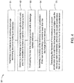
- Fig. 4 is a flowchart illustrating an electrical machining method 50 in accordance with an exemplary embodiment of the present disclosure.
- the electrical machining method 50 comprises step 51-55.
- a workpiece is machined by an electrical machining device.
- the electrical machining device is a High Speed Electro Erosion (HSEE) device performing a HSEE process on the workpiece.
- the electrical machining device comprises an electrode which machines the workpiece at a feedrate.
- the workpiece and the electrode are energized by a power supply.
- the power supply comprises a constant voltage source.
- step 52 a discharge current passing through the electrode and the workpiece is detected to obtain a real time discharge current.
- step 53 the real time discharge current is compared with a discharge current reference to obtain a compared result.
- the discharge current reference may be predetermined based on an operating condition of the electrical machining process.
- step 54 is performed.
- the feedrate of the electrode is increased at a first acceleration.
- the increasing of the feedrate comprises multiplying the feedrate by a first override ratio higher than an override ratio reference.
- the override ratio reference may be predetermined based on the operating condition of the electrical machining process. In some embodiments, the override ratio reference is set to 100%. In this case, the first override ratio is higher than 100%.
- step 55 is performed.
- the feedrate of the electrode is decreased at a second acceleration which has an absolute value higher than that of the first acceleration.
- the decreasing of the feedrate comprises multiplying the feedrate by a second override ratio lower than the override ratio reference.
- the override ratio reference is set to 100%.
- the second override ratio is lower than 100%.
- steps 52-55 are repeated a plurality of times after the above-mentioned step 54 or step 55, until the real time discharge current stabilizes around the discharge current reference.
- the electrical machining method disclosed in the present disclosure can automatically regulate the feedrate in order to achieve a stable machining process and avoid short circuit and breakage of the electrode.
- Embodiments of the present disclosure also refer to a machining method using a hybrid machining system comprising a cutter, an electrode and a toolholder, as illustrated in Fig. 2 .
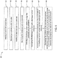
- Fig. 5 is a flowchart illustrating a machining method 60 using a hybrid machining system in accordance with an exemplary embodiment of the present disclosure. While actions of the method are illustrated as functional blocks, the order of the blocks and the separation of the actions among the various blocks shown in Figs. 5 are not intended to be limiting.
- the blocks may be performed in a different order and an action associated with one block may be combined with one or more other blocks or may be sub-divided into a number of blocks.
- the method 60 comprises step 61-68, wherein steps 61-62 refer to operating the system in a first mode, i.e., a mechanical machining mode.
- Operating the system in the first mode comprises holding the cutter with the toolholder and machining a workpiece with the cutter, as respectively shown in step 61 and step 62.
- Steps 63-68 refer to operating the system in a second mode, i.e., an electrical machining mode.
- the toolholder is operated to hold the electrode.
- the cutter is disassembled from the toolholder before the electrode is assembled with the toolholder. Then, the workpiece is machined by the electrode, as shown in step 64.
- Steps 65-68 are similar to steps 52-55 illustrated in Fig. 4 , which will not be repeated here.
Landscapes
- Engineering & Computer Science (AREA)
- Mechanical Engineering (AREA)
- Chemical & Material Sciences (AREA)
- Chemical Kinetics & Catalysis (AREA)
- Electrochemistry (AREA)
- Manufacturing & Machinery (AREA)
- Electrical Discharge Machining, Electrochemical Machining, And Combined Machining (AREA)
- Numerical Control (AREA)
Abstract
Description
- Embodiments of the present disclosure relate generally to electrical machining devices and methods, and hybrid machining systems and methods.
- Electrical machining is a manufacturing process whereby a desired shape is obtained using electrical discharges. Material is removed from the workpiece by a series of rapidly recurring current discharges between the electrode and the workpiece. Conventional electrical machining methods have problems of low efficiency and stability.
- A conventional machining process combination usually requires two or more independent machining devices in sequence, each of which requires particular hardware and software resources, thus causing a high complexity for system design and a time-consuming process for tool assembling and disassembly.
- Therefore, it is desirable to provide new electrical machining devices and methods, and hybrid machining systems and methods to solve at least one of the above-mentioned problems.
- In one aspect, an electrical machining method comprises machining a workpiece by an electrical machining device comprising an electrode; increasing a feedrate of the electrode at a first acceleration if a discharge current passing through the electrode and the workpiece is lower than a discharge current reference; and decreasing the feedrate of the electrode at a second acceleration if the discharge current is higher than the discharge current reference, wherein the second acceleration has an absolute value higher than that of the first acceleration.
- In another aspect, an electrical machining device comprises an electrode for machining a workpiece and an feedrate regulator. The feedrate regulator is configured to increase a feedrate of the electrode at a first acceleration if a discharge current passing through the electrode and the workpiece is lower than a discharge current reference, and decrease the feedrate of the electrode at a second acceleration if the discharge current is higher than the discharge current reference; wherein the second acceleration has an absolute value higher than that of the first acceleration.
- In another aspect, a hybrid machining system comprises a cutter for machining a workpiece in a first mode, an electrode for machining the workpiece in a second mode, and a hybrid controller. The hybrid controller is configured to control the cutter to machine the workpiece in the first mode. The hybrid controller is also configured to increase a feedrate of the electrode at a first acceleration in the second mode if a discharge current passing through the electrode and the workpiece is lower than a discharge current reference, and decrease the feedrate of the electrode at a second acceleration in the second mode if the discharge current is higher than the discharge current reference, wherein the second acceleration has an absolute value higher than that of the first acceleration.
- In another aspect, a machining method using a hybrid machining system comprises operating the system in a first mode and operating the system in a second mode, wherein the hybrid machining system comprises a cutter, an electrode and a toolholder. The operating the system in the first mode comprises holding the cutter with the toolholder; and machining a workpiece with the cutter. The operating the system in the second mode comprises holding the electrode with the toolholder; machining the workpiece with the electrode; increasing a feedrate of the electrode at a first acceleration if a discharge current passing through the electrode and the workpiece is lower than a discharge current reference; and decreasing the feedrate of the electrode at a second acceleration if the discharge current is higher than the discharge current reference; wherein the second acceleration has an absolute value higher than that of the first acceleration.
- These and other features, aspects, and advantages of the present disclosure will become better understood when the following detailed description is read with reference to the accompanying drawings in which like characters represent like parts throughout the drawings, wherein:
-
Fig. 1 is a sketch view illustrating an electrical machining device in accordance with an exemplary embodiment of the present disclosure; -
Fig. 2 is a sketch view illustrating a hybrid machining system in accordance with an exemplary embodiment of the present disclosure; -
Fig. 3 is a graph illustrating a relation between an override ratio of a feedrate of and a discharge current of the electrical machining device in accordance with an exemplary embodiment of the present disclosure; -
Fig. 4 is a flowchart illustrating an electrical machining method in accordance with an exemplary embodiment of the present disclosure; and -
Fig. 5 is a flowchart illustrating a machining method using a hybrid machining system in accordance with an exemplary embodiment of the present disclosure. - In an effort to provide a concise description of these embodiments, not all features of an actual implementation are described in one or more specific embodiments. It should be appreciated that in the development of any such actual implementation, as in any engineering or design project, numerous implementation-specific decisions must be made to achieve the developers' specific goals, such as compliance with system-related and business-related constraints, which may vary from one implementation to another. Moreover, it should be appreciated that such a development effort might be complex and time consuming, but would nevertheless be a routine undertaking of design, fabrication, and manufacture for those of ordinary skill having the benefit of the present disclosure.
- Unless defined otherwise, technical and scientific terms used herein have the same meaning as is commonly understood by one of ordinary skill in the art to which the present disclosure belongs. The terms "first," "second," "third," "fourth," and the like, as used herein do not denote any order, quantity, or importance, but rather are used to distinguish one element from another. Also, the terms "a" and "an" do not denote a limitation of quantity, but rather denote the presence of at least one of the referenced items. The term "or" is meant to be inclusive and mean either any, several, or all of the listed items. The use of "including," "comprising," or "having," and variations thereof herein are meant to encompass the items listed thereafter and equivalents thereof as well as additional items.
- In one aspect, embodiments of the present disclosure refer to an electrical machining device which can be widely applied in parts machining. In some embodiments, the electrical machining device is a High Speed Electro Erosion (HSEE) device which performs a HSEE process. The HSEE process, for example, BlueArc™, can be applied to rough cut high strength alloys.
-
Fig. 1 shows a sketch view of anelectrical machining device 10 for machining aworkpiece 20, in accordance with an exemplary embodiment of the present disclosure. - Referring to
Fig. 1 , theelectrical machining device 10 comprises anelectrode 11 and afeedrate regulator 13. Theelectrode 11 is configured to machine theworkpiece 20 at a feedrate. Thefeedrate regulator 13 is configured to increase the feedrate of theelectrode 11 at a first acceleration if a discharge current passing through the electrode and the workpiece is lower than a discharge current reference. Thefeedrate regulator 13 is configured to decrease the feedrate of the electrode at a second acceleration if the discharge current is higher than the discharge current reference. The second acceleration has an absolute value higher than that of the first acceleration. The first or second acceleration used herein may be an average acceleration. The "absolute value" used herein refers to a non-negative value of a number without regard to its sign. - The
electrical machining device 10 further comprises apower supply 14 which is coupled with theelectrode 11 and theworkpiece 20 for energizing one of the workpiece and the electrode as an anode and the other as a cathode, in order to produce discharges between theelectrode 11 and theworkpiece 20 when theelectrode 11 is positioned adjacent to theworkpiece 20. The discharge current passing through theelectrode 11 and theworkpiece 20 is generated in this case, and the discharge current varies during the machining process. In some embodiments, thepower supply 14 comprises a constant voltage source for outputting a preset voltage which remains roughly unchanged during the machining process. - The
electrical machining device 10 further comprises a dischargecurrent detector 12 and acomparator 17. The dischargecurrent detector 12 is coupled with theelectrode 11 and theworkpiece 20 for detecting the discharge current to obtain a real time discharge current. Thecomparator 17 is configured to compare the detected real time discharge current with the discharge current reference to obtain a compared result. Thefeedrate regulator 13 increases or decreases the feedrate of the electrode according to the compared result. The discharge current reference can be predetermined based on an operating condition of the electrical machining device. For example, the discharge current reference may be predetermined based on a maximum of the discharge current, a minimum of the discharge current, an override ratio reference or a combination thereof. In some embodiments, the discharge current reference is set to 2500A. - The
electrical machining device 10 further comprises atoolholder 15 and amotion unit 16. Theelectrode 11 is held by thetoolholder 15. Themotion unit 16 is coupled with at least one of thetoolholder 15 and theworkpiece 20 for positioning thetoolholder 15 as well as theelectrode 11 relative to theworkpiece 20. In the embodiment illustrated inFig. 1 , themotion unit 16 is coupled with thetoolholder 15 to move thetoolholder 15 and theelectrode 11 relative to theworkpiece 20. In some other embodiments themotion unit 16 may be coupled with the workpiece to move the workpiece relative to the electrode. - When the
electrical machining device 10 is working, thepower supply 14 is switched on to energize theelectrode 11 and theworkpiece 20. Themotion unit 16 drives theelectrode 11 to advance towards theworkpiece 20 at an initial feedrate. A discharge current passing through theelectrode 11 and theworkpiece 20 can be generated when theelectrode 11 is adjacent to theworkpiece 20. The discharge current is regarded as a load condition indicator during the machining process, so the feedrate can be adjusted based on the real time discharge current. - The
feedrate regulator 13 is coupled with themotion unit 16 for adjusting the feedrate of theelectrode 11 according to the compared result. Specifically, thefeedrate regulator 13 increases or decreases the feedrate by controlling themotion unit 16. If the real time discharge current is lower than the discharge current reference, thefeedrate regulator 13 increases the feedrate of theelectrode 11 at the first acceleration, in order to improve a machining efficiency. If the real time discharge current is higher than the discharge current reference, thefeedrate regulator 13 decreases the feedrate of theelectrode 11 at the second acceleration, in order to achieve better stability of machining process. As mentioned before, the second acceleration has an absolute value higher than that of the first acceleration, which indicates that the feedrate of the electrode increases more slowly than it decreases, in such a manner that the stability of the machining process can be further improved and statuses of over-speed or over-current can be avoided. - In some embodiments, the
feedrate regulator 13 increases the feedrate by multiplying the feedrate by a first override ratio higher than an override ratio reference, and decreases the feedrate by multiplying the feedrate by a second override ratio lower than the override ratio reference. The override ratio reference can be predetermined based on the operating condition of the electrical machining device. In some embodiments, the override ratio reference may be predetermined based on a maximum of the override ratio, a minimum of the override ratio, a discharge current reference or a combination thereof. For example, the override ratio reference may be set to 100%. Thus, the first override ratio is higher than 100%, and the second override ratio is lower than 100%. - More specifically, the
feedrate regulator 13 increases the feedrate by adjusting the feedrate to a first target feedrate value which is calculated by: F t1 = Fr * R 1, and decreases the feedrate by adjusting the feedrate to a second target feedrate value which is calculated by: F t2 = Fr * R 2, wherein F t1 represents the first target feedrate, F t2 represents the second target feedrate, Fr represents a real time feedrate, R1 represents the first override ratio, and R2 represents the second override ratio. - In some embodiments, the
electrical machining device 10 comprises acalculator 19 for calculating the first override ratio by:



- In general, relations between the override ratio of the feedrate and the real time discharge current can be illustrated as a
broken line 70 shown inFig. 3 . Thebroken line 70 comprises afirst segment 71 and asecond segment 72. Thefirst segment 71 is a straight line defined between a first point A and a second point B, which illustrates the relation between the first override ratio and the discharge current. Thesecond segment 72 is a straight line defined between the second point B and a third point C, which illustrates the relation between the second override ratio and the discharge current. The first point A indicates a status in which the real time discharge current equals the minimum of discharge current Imin , and the override ratio equals the maximum of the override ratio Rmax . The second point B indicates a status in which the real time discharge current equals the discharge current reference Iref , and the override ratio equals the override ratio reference Rref. The third point C indicates a status in which the real time discharge current equals the maximum of discharge current Imax , and the override ratio equals the minimum of the override ratio Rmin . As shown inFig. 3 , the first and second segments have different slopes. Thefirst segment 71 has a first slope equal to
second segment 72 has a second slope equal to

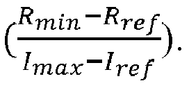
Fig. 3 , Iref is set to 2500A, Rref is set to 100%, Imin is set to 0, Imax is set to 3000A, Rmin is set to 0% and Rmax is set to 120%. - In some other embodiments, the broken line may comprise three or more segments which have different slopes, in such a manner that a performance of the device can be further improved.
- In some embodiments, the
electrical machining device 10 further comprises apower supply controller 18 for switching on or off thepower supply 14. Theelectrical machining device 10 may further comprise adata storage unit 21 for storing at least one of the real time discharge current, the first override ratio, the second override ratio, the target feedrate, the discharge current
reference, the override ratio reference, the minimum and maximum of the discharge current, and the minimum and maximum of the override ratio. Theelectrical machining device 10 may further comprise acommunication unit 22 for communicating signals among the dischargecurrent detector 12, thecomparator 17, thefeedrate regulator 13, thepower supply 14, thepower supply controller 18, thecalculator 19, and thedata storage unit 21. - The
feedrate regulator 13, thecomparator 17, the dischargecurrent detector 12, thepower supply controller 18, thecalculator 19, thedata storage unit 21 and thecommunication unit 22 may be configured independently from each other. Or, at least some of them may be integrated. For example, as shown inFig. 1 , the dischargecurrent detector 12 and thecommunication unit 22 are integrated as aninterface circuit 23, while thefeedrate regulator 13, thecomparator 17, thepower supply controller 18, thecalculator 19, and thedata storage unit 21 are integrated as anelectrical machining controller 24. - Embodiments of the present disclosure also refer to a hybrid machining system which combines a mechanical machining function and an electrical machining function. The two functions share hardware and software resources, in order to simplify the system and reduce cost.
-
Fig. 2 shows a sketch view of ahybrid machining system 30 in accordance with an exemplary embodiment of the present disclosure. Thehybrid machining system 30 is configured to machine aworkpiece 40 mounted on abase 49. Thehybrid machining system 30 comprises acutter 37, anelectrode 31 and ahybrid controller 44. - The
hybrid machining system 30 has two working modes, i.e., a first mode and a second mode, and can be switched freely between the two modes. In the first mode, thehybrid controller 44 controls thecutter 37 to machine aworkpiece 40 by a mechanical machining method, such as turning, milling and drilling. In the second mode, thehybrid controller 44 controls theelectrode 31 to machine theworkpiece 40 by an electrical machining method. The first mode can be used to perform a fine machining process on the workpiece which has high machining accuracy, and the second mode can be used to perform a rough machining process on the workpiece which has high machining efficiency. When the workpiece need to be machined accurately, the first mode is selected. When the workpiece need to be machined roughly, the second mode is selected. In some embodiments, a workpiece can be machined by the second mode to remove unnecessary part of the workpiece efficiently and form a rough shape, and then machined accurately by the first mode in order to increase dimensional accuracy and surface quality. The workpiece is mounted on the base during the whole machining process without any assembling or dissembling process, in such a manner that machining duration can be reduced and machining efficiency can be increased. - The
hybrid machining system 30 further comprises atoolholder 35 for holding thecutter 37 in the first mode and holding theelectrode 31 in the second mode, and amotion unit 36 coupled with at least one of thetoolholder 35 and theworkpiece 40 for positioning the toolholder 35 (as well as thecutter 37 or the electrode 31) relative to the workpiece. Thehybrid controller 44 comprises afeedrate regulator 33 coupled with themotion unit 36 and configured to adjust a feedrate of thecutter 37 or theelectrode 31 by controlling themotion unit 36. - The
hybrid machining system 30 further comprises apower supply 34, and a dischargecurrent detector 32. Thehybrid controller 44 comprises acomparator 46. Thepower supply 34, the dischargecurrent detector 32 and thecomparator 46 work in the second mode. Thepower supply 34 is coupled with and configured to energize theelectrode 31 and theworkpiece 40. The dischargecurrent detector 32 is coupled with theelectrode 31 andworkpiece 40 for detecting a real time discharge current passing through theelectrode 31 and theworkpiece 40. Thecomparator 46 is configured to compare the real time discharge current with a discharge current reference to obtain a compared result. Thefeedrate regulator 33 in thehybrid controller 44 is configured to increase or decrease the feedrate of theelectrode 31 based on the compared result. The specific controlling method of thefeedrate regulator 33 is similar to that of thefeedrate regulator 13 as shown in theFig. 1 , which will not be repeated here. - The
hybrid controller 44 may further comprise apower supply controller 38, acalculator 39, and adata storage unit 41, which are similar to the corresponding components of theelectrical machining device 10 illustrated inFig. 1 and description thereof will not be repeated here. - The
hybrid machining system 30 further comprises acommunication unit 42 for communicating signals among the dischargecurrent detector 32, thehybrid controller 44 and thepower supply 34. In some embodiments, thecommunication unit 42 may be integrated with the dischargecurrent detector 32 as aninterface circuit 43. - In general, the first mode and the second mode at least share the
toolholder 35, themotion unit 36, and thefeedrate regulator 33, in such a manner that hardware resources can be saved, thus simplifying circuit structure and reducing production cost. - In some embodiments, the
hybrid machining system 30 is manufactured based on a mechanical machining device which comprises a cutter, a toolholder, a motion unit and a computer numerical controller (CNC). The mechanical machining device may be light duty machining device. The CNC is configured to adjust a feedrate of the toolholder (as well as the cutter) based on a given override ratio. An electrode, an interface circuit and an electrode controlling module are added to the mechanical machining device to form the hybrid machining system. Specifically, in the second mode, the interface circuit is coupled between the electrode and the CNC and configured to acquire a real time discharge current from the electrode and transmit it to the electrode controlling module. The electrode controlling module is configured to calculate an override ratio based on the real time discharge current, and provide the override ratio to the CNC. Then, the CNC adjusts the feedrate of the toolholer as well as the electrode according to the override ratio. The electrode controlling module may be integrated with the CNC. As such, the CNC is able to adjust the feedrate of the electrode based on the discharge current in the second mode, and the electrical machining method is embedded into the mechanical machining device. - Embodiments of the present disclosure also refer to an electrical machining method, which can balance machining efficiency and machining stability well.
-
Fig. 4 is a flowchart illustrating anelectrical machining method 50 in accordance with an exemplary embodiment of the present disclosure. Referring toFig. 4 , theelectrical machining method 50 comprises step 51-55. - In
step 51, a workpiece is machined by an electrical machining device. In some embodiments, the electrical machining device is a High Speed Electro Erosion (HSEE) device performing a HSEE process on the workpiece. The electrical machining device comprises an electrode which machines the workpiece at a feedrate. The workpiece and the electrode are energized by a power supply. In some embodiments, the power supply comprises a constant voltage source. - In
step 52, a discharge current passing through the electrode and the workpiece is detected to obtain a real time discharge current. - In
step 53, the real time discharge current is compared with a discharge current reference to obtain a compared result. The discharge current reference may be predetermined based on an operating condition of the electrical machining process. - If the real time discharge current is lower than the discharge current reference,
step 54 is performed. Instep 54, the feedrate of the electrode is increased at a first acceleration. The increasing of the feedrate comprises multiplying the feedrate by a first override ratio higher than an override ratio reference. The override ratio reference may be predetermined based on the operating condition of the electrical machining process. In some embodiments, the override ratio reference is set to 100%. In this case, the first override ratio is higher than 100%. The increasing of the feedrate comprises adjusting the feedrate to a first target feedrate which is calculated by: F t1 = Fr * R 1, wherein F t1 represents the first target feedrate, Fr represents a real time feedrate, and R 1 represents the first override ratio. - In some embodiments, the first override ratio is calculated by

- If the real time current is higher than the discharge current reference,
step 55 is performed. Instep 55, the feedrate of the electrode is decreased at a second acceleration which has an absolute value higher than that of the first acceleration. The decreasing of the feedrate comprises multiplying the feedrate by a second override ratio lower than the override ratio reference. In some embodiments, the override ratio reference is set to 100%. In this case, the second override ratio is lower than 100%. The decreasing of the feedrate comprises adjusting the feedrate to a second target feedrate which is calculated by: F t2 = Fr * R 2, wherein F t2 represents the second target feedrate, and R 2 represents the second override ratio. - In some embodiments, the second override ratio is calculated by


- In some embodiments, steps 52-55 are repeated a plurality of times after the above-mentioned
step 54 orstep 55, until the real time discharge current stabilizes around the discharge current reference. - The electrical machining method disclosed in the present disclosure can automatically regulate the feedrate in order to achieve a stable machining process and avoid short circuit and breakage of the electrode.
- Embodiments of the present disclosure also refer to a machining method using a hybrid machining system comprising a cutter, an electrode and a toolholder, as illustrated in
Fig. 2 . -
Fig. 5 is a flowchart illustrating amachining method 60 using a hybrid machining system in accordance with an exemplary embodiment of the present disclosure. While actions of the method are illustrated as functional blocks, the order of the blocks and the separation of the actions among the various blocks shown inFigs. 5 are not intended to be limiting. - For example, the blocks may be performed in a different order and an action associated with one block may be combined with one or more other blocks or may be sub-divided into a number of blocks.
- Referring to
Fig. 5 , themethod 60 comprises step 61-68, wherein steps 61-62 refer to operating the system in a first mode, i.e., a mechanical machining mode. Operating the system in the first mode comprises holding the cutter with the toolholder and machining a workpiece with the cutter, as respectively shown instep 61 andstep 62. - Steps 63-68 refer to operating the system in a second mode, i.e., an electrical machining mode. In
step 63, the toolholder is operated to hold the electrode. In some embodiments, the cutter is disassembled from the toolholder before the electrode is assembled with the toolholder. Then, the workpiece is machined by the electrode, as shown instep 64. - Steps 65-68 are similar to steps 52-55 illustrated in
Fig. 4 , which will not be repeated here. - As will be understood by those familiar with the art, the present disclosure may be embodied in other specific forms without depending from the spirit or essential characteristics thereof. Accordingly, the disclosures and descriptions herein are intended to be illustrative, but not limiting, of the scope of the disclosure which is set forth in the following claims.
Claims (12)
- An electrical machining method comprising:machining a workpiece by an electrical machining device comprising an electrode;increasing a feedrate of the electrode at a first acceleration if a discharge current passing through the electrode and the workpiece is lower than a discharge current reference; anddecreasing the feedrate of the electrode at a second acceleration if the discharge current is higher than the discharge current reference, wherein the second acceleration has an absolute value higher than that of the first acceleration.
- The method according to claim 1, further comprising energizing the workpiece and the electrode by a constant voltage source.
- The method according to claim 1 or 2, further comprising:detecting the discharge current passing through the electrode and the workpiece; andcomparing the discharge current with the discharge current reference.
- The method according to claim 1, 2 or 3 wherein increasing the feedrate of the electrode comprises multiplying the feedrate by a first override ratio higher than an override ratio reference and decreasing the feedrate of the electrode comprises multiplying the feedrate by a second override ratio lower than the override ratio reference.
- The method according to claim 4, wherein the first override ratio is calculated by


- An electrical machining device comprising:an electrode for machining a workpiece; anda feedrate regulator for increasing a feedrate of the electrode at a first acceleration if a discharge current passing through the electrode and the workpiece is lower than a discharge current reference, and decreasing the feedrate of the electrode at a second acceleration if the discharge current is higher than the discharge current reference, wherein the second acceleration has an absolute value higher than that of the first acceleration.
- The device according to claim 6, further comprising:a discharge current detector coupled with the electrode and the workpiece for detecting the discharge current; anda comparator for comparing the detected discharge current with the discharge current reference.
- The device according to claim 6 or 7, further comprising a constant voltage source for energizing the workpiece and the electrode.
- The device according to claim 6, 7 or 8 further comprising:a toolholder for holding the electrode; anda motion unit coupled with at least one of the toolholder and the workpiece for positioning the electrode relative to the workpiece;wherein the feedrate regulator is coupled with the motion unit and configured to increase or decrease the feedrate by controlling the motion unit.
- A hybrid machining system, comprising:a cutter for machining a workpiece in a first mode;an electrode for machining the workpiece in a second mode;a hybrid controller for controlling the cutter to machine the workpiece in the first mode, increasing a feedrate of the electrode at a first acceleration in the second mode if a discharge current passing through the electrode and the workpiece is lower than a discharge current reference, and decreasing the feedrate of the electrode at a second acceleration in the second mode if the discharge current is higher than the discharge current reference, wherein the second acceleration has an absolute value higher than that of the first acceleration.
- The system according to claim 10, further comprising:a toolholder for holding the cutter in the first mode and holding the electrode in the second mode; anda motion unit coupled with at least one of the toolholder and the workpiece for positioning the toolholder relative to the workpiece;wherein the hybrid controller is coupled with the motion unit and configured to increase or decrease the feedrate by controlling the motion unit.
- A machining method using a hybrid machining system comprising a cutter, an electrode and a toolholder, the method comprising:operating the system in a first mode comprising:holding the cutter with the toolholder, andmachining a workpiece with the cutter; andoperating the system in a second mode comprising:holding the electrode with the toolholder,machining the workpiece with the electrode,increasing a feedrate of the electrode at a first acceleration if a discharge current passing through the electrode and the workpiece is lower than a discharge current reference, anddecreasing the feedrate of the electrode at a second acceleration if the discharge current is higher than the discharge current reference, wherein the second acceleration has an absolute value higher than that of the first acceleration.
Applications Claiming Priority (1)
| Application Number | Priority Date | Filing Date | Title |
|---|---|---|---|
| CN201610802471.3A CN107790834B (en) | 2016-09-05 | 2016-09-05 | Apparatus and method for electrical machining, system and method for hybrid machining |
Publications (1)
| Publication Number | Publication Date |
|---|---|
| EP3296049A1 true EP3296049A1 (en) | 2018-03-21 |
Family
ID=59790984
Family Applications (1)
| Application Number | Title | Priority Date | Filing Date |
|---|---|---|---|
| EP17189331.6A Pending EP3296049A1 (en) | 2016-09-05 | 2017-09-05 | Electrical machining device and method, hybrid machining system and method |
Country Status (4)
| Country | Link |
|---|---|
| US (1) | US11014178B2 (en) |
| EP (1) | EP3296049A1 (en) |
| JP (1) | JP6998700B2 (en) |
| CN (1) | CN107790834B (en) |
Families Citing this family (2)
| Publication number | Priority date | Publication date | Assignee | Title |
|---|---|---|---|---|
| US10953483B2 (en) * | 2017-11-15 | 2021-03-23 | General Electric Company | Tool electrode for and methods of electrical discharge machining |
| CN111796558B (en) * | 2020-06-08 | 2021-06-08 | 五邑大学 | Multi-axis linkage real-time dynamic look-ahead trajectory planning method and device and storage medium |
Citations (8)
| Publication number | Priority date | Publication date | Assignee | Title |
|---|---|---|---|---|
| US4152569A (en) * | 1977-05-13 | 1979-05-01 | Colt Industries Operating Corp. | Servo feed circuit for electrical discharge machining apparatus |
| US4510364A (en) * | 1980-01-22 | 1985-04-09 | Mitsubishi Denki Kabushiki Kaisha | Electric discharge machining apparatus |
| US4667079A (en) * | 1983-06-08 | 1987-05-19 | Fanuc Ltd. | Electrode retraction control system of electric discharge machine |
| US4864091A (en) * | 1988-03-15 | 1989-09-05 | Ag Fur Industrielle, Elektronik Agie | Servocontrol device for an erosion machine |
| US20030098293A1 (en) * | 2001-11-29 | 2003-05-29 | Mitsubishi Denki Kabushiki Kaisha | Wire electric-discharge machining apparatus |
| US20070034609A1 (en) * | 2005-08-10 | 2007-02-15 | Fanuc Ltd | Electric discharge machining apparatus |
| US20110243677A1 (en) * | 2007-05-29 | 2011-10-06 | Metem Corporation | Method and apparatus for milling thermal barrier coated metals |
| US20130062318A1 (en) * | 2010-05-21 | 2013-03-14 | Mitsubishi Electric Corporation | Wire discharge machine |
Family Cites Families (14)
| Publication number | Priority date | Publication date | Assignee | Title |
|---|---|---|---|---|
| US4322595A (en) | 1980-07-29 | 1982-03-30 | National Research Development Corporation | Arc monitor for electrical discharge machining |
| US5360957A (en) | 1992-06-11 | 1994-11-01 | General Electric Company | Controlled apparatus for electrical discharge machining |
| DE19856099A1 (en) * | 1998-12-04 | 2000-07-06 | Agie Sa | Controlled erosion machining electrode retraction, e.g. when a short-circuit occurs, comprises simultaneous retraction along the machining path and a vector of direction conforming to each point of the machining path |
| US6225589B1 (en) | 1999-03-15 | 2001-05-01 | Stephen Bartok | Electric discharge machining apparatus |
| US20090134126A1 (en) * | 2004-01-29 | 2009-05-28 | Mitsubishi Electric Corporation | Electric-discharge machining apparatus and electric-discharge machining method |
| ES2353520T3 (en) | 2005-08-01 | 2011-03-02 | Agie Charmilles Sa | PROCEDURE OF OPERATION OF A MACHINING MACHINE BY ELECTROEROSION AND A SYSTEM OF MACHINING BY ELECTROEROSION. |
| US7394040B2 (en) * | 2006-03-31 | 2008-07-01 | General Electric Company | Electromachining process and apparatus |
| US7741576B2 (en) | 2007-05-11 | 2010-06-22 | General Electric Company | Apparatus and method for hybrid machining a workpiece |
| US8560110B2 (en) | 2009-06-19 | 2013-10-15 | General Electric Company | Electroerosion control system and a dual mode control system |
| JP5465969B2 (en) | 2009-09-30 | 2014-04-09 | 株式会社ミツトヨ | Processing machine |
| CN102133666B (en) | 2010-01-22 | 2014-08-20 | 通用电气公司 | Cutter joint assembly and processing system |
| CN103084675B (en) * | 2013-01-15 | 2016-09-21 | 洛阳信成精密机械有限公司 | A kind of electric discharge machine processes method and the control system that feeding automatically controls |
| WO2014117226A1 (en) * | 2013-02-04 | 2014-08-07 | Anca Pty Ltd | Pulse and gap control for electrical discharge machining equipment |
| CN103624684A (en) | 2013-12-05 | 2014-03-12 | 湖南大学 | Electrospark trimming device for metal binding agent superabrasive formed grinding wheel for sawtooth processing |
-
2016
- 2016-09-05 CN CN201610802471.3A patent/CN107790834B/en active Active
-
2017
- 2017-07-25 US US15/658,855 patent/US11014178B2/en active Active
- 2017-08-22 JP JP2017158969A patent/JP6998700B2/en active Active
- 2017-09-05 EP EP17189331.6A patent/EP3296049A1/en active Pending
Patent Citations (8)
| Publication number | Priority date | Publication date | Assignee | Title |
|---|---|---|---|---|
| US4152569A (en) * | 1977-05-13 | 1979-05-01 | Colt Industries Operating Corp. | Servo feed circuit for electrical discharge machining apparatus |
| US4510364A (en) * | 1980-01-22 | 1985-04-09 | Mitsubishi Denki Kabushiki Kaisha | Electric discharge machining apparatus |
| US4667079A (en) * | 1983-06-08 | 1987-05-19 | Fanuc Ltd. | Electrode retraction control system of electric discharge machine |
| US4864091A (en) * | 1988-03-15 | 1989-09-05 | Ag Fur Industrielle, Elektronik Agie | Servocontrol device for an erosion machine |
| US20030098293A1 (en) * | 2001-11-29 | 2003-05-29 | Mitsubishi Denki Kabushiki Kaisha | Wire electric-discharge machining apparatus |
| US20070034609A1 (en) * | 2005-08-10 | 2007-02-15 | Fanuc Ltd | Electric discharge machining apparatus |
| US20110243677A1 (en) * | 2007-05-29 | 2011-10-06 | Metem Corporation | Method and apparatus for milling thermal barrier coated metals |
| US20130062318A1 (en) * | 2010-05-21 | 2013-03-14 | Mitsubishi Electric Corporation | Wire discharge machine |
Also Published As
| Publication number | Publication date |
|---|---|
| US20180065200A1 (en) | 2018-03-08 |
| JP6998700B2 (en) | 2022-01-18 |
| CN107790834A (en) | 2018-03-13 |
| US11014178B2 (en) | 2021-05-25 |
| JP2018065241A (en) | 2018-04-26 |
| CN107790834B (en) | 2019-11-08 |
Similar Documents
| Publication | Publication Date | Title |
|---|---|---|
| Zhou et al. | Improving EDM performance by adapting gap servo-voltage to machining state | |
| CN105629887A (en) | Controller for controlling machine tool having cutting condition change function | |
| EP3588220A1 (en) | Smart adjustment system and method thereof | |
| CN110463005B (en) | Laser driving power supply | |
| US11630440B2 (en) | Wire disconnection prediction device | |
| EP2272613A2 (en) | Wire-cut electric discharge machine with function to suppress local production of streaks during finish machining | |
| US11014178B2 (en) | Electrical machining device and method, hybrid machining system and method | |
| US20150127136A1 (en) | Wire-cut electrical discharge machining machine and method of machining therein | |
| US20180056441A1 (en) | Laser controller | |
| US20030080094A1 (en) | Electric discharge machining device and electric discharge machining method | |
| US10274938B2 (en) | Numerical control unit and NC program creating unit | |
| EP1319459B1 (en) | Wire electric-discharge machining apparatus | |
| JP4569973B2 (en) | Electric discharge machining apparatus and method, and method for determining occurrence of electric discharge | |
| EP2730986A2 (en) | Wire electric discharge machine controller, wire electric discharge machine, and wire electric discharge machining method | |
| CN117120198B (en) | Numerical control devices and computer-readable storage media | |
| US20240361746A1 (en) | Method and a device for optimization of die-sinking electrical discharge machining | |
| JP5190973B1 (en) | Wire cut electric discharge machining method and wire cut electric discharge machining apparatus | |
| CN112684761A (en) | Numerical controller | |
| US11507062B2 (en) | Numerical control apparatus | |
| JPH068051A (en) | Electric discharge machining method and device therefor | |
| JPH02256448A (en) | Abnormality detecting device for cutter tool in machine tool | |
| KR200382717Y1 (en) | Cnc small hole electric discharge machine | |
| CN107283009B (en) | Control system and processing method for electric spark processing | |
| CN121152353A (en) | Laser control methods, devices, storage media, electronic equipment, and laser machines | |
| KR100564159B1 (en) | Enhancement of surface finish of workpieces |
Legal Events
| Date | Code | Title | Description |
|---|---|---|---|
| PUAI | Public reference made under article 153(3) epc to a published international application that has entered the european phase |
Free format text: ORIGINAL CODE: 0009012 |
|
| STAA | Information on the status of an ep patent application or granted ep patent |
Free format text: STATUS: THE APPLICATION HAS BEEN PUBLISHED |
|
| AK | Designated contracting states |
Kind code of ref document: A1 Designated state(s): AL AT BE BG CH CY CZ DE DK EE ES FI FR GB GR HR HU IE IS IT LI LT LU LV MC MK MT NL NO PL PT RO RS SE SI SK SM TR |
|
| AX | Request for extension of the european patent |
Extension state: BA ME |
|
| STAA | Information on the status of an ep patent application or granted ep patent |
Free format text: STATUS: REQUEST FOR EXAMINATION WAS MADE |
|
| 17P | Request for examination filed |
Effective date: 20180921 |
|
| RBV | Designated contracting states (corrected) |
Designated state(s): AL AT BE BG CH CY CZ DE DK EE ES FI FR GB GR HR HU IE IS IT LI LT LU LV MC MK MT NL NO PL PT RO RS SE SI SK SM TR |
|
| STAA | Information on the status of an ep patent application or granted ep patent |
Free format text: STATUS: EXAMINATION IS IN PROGRESS |
|
| 17Q | First examination report despatched |
Effective date: 20200915 |