EP3295965B1 - Device of a support module for rotary instrument holder - Google Patents
Device of a support module for rotary instrument holder Download PDFInfo
- Publication number
- EP3295965B1 EP3295965B1 EP17190501.1A EP17190501A EP3295965B1 EP 3295965 B1 EP3295965 B1 EP 3295965B1 EP 17190501 A EP17190501 A EP 17190501A EP 3295965 B1 EP3295965 B1 EP 3295965B1
- Authority
- EP
- European Patent Office
- Prior art keywords
- rotary instrument
- motor
- modules
- module
- holder
- Prior art date
- Legal status (The legal status is an assumption and is not a legal conclusion. Google has not performed a legal analysis and makes no representation as to the accuracy of the status listed.)
- Active
Links
- 230000002093 peripheral effect Effects 0.000 claims description 10
- 230000000249 desinfective effect Effects 0.000 claims description 8
- 239000012530 fluid Substances 0.000 claims description 7
- 238000004140 cleaning Methods 0.000 claims description 5
- 239000000463 material Substances 0.000 claims description 4
- 238000009792 diffusion process Methods 0.000 claims description 3
- 230000001050 lubricating effect Effects 0.000 claims description 3
- 239000002654 heat shrinkable material Substances 0.000 claims description 2
- 239000011347 resin Substances 0.000 claims description 2
- 229920005989 resin Polymers 0.000 claims description 2
- 239000000945 filler Substances 0.000 claims 2
- 238000007789 sealing Methods 0.000 description 5
- 238000004659 sterilization and disinfection Methods 0.000 description 5
- 230000000712 assembly Effects 0.000 description 2
- 238000000429 assembly Methods 0.000 description 2
- 238000001035 drying Methods 0.000 description 2
- 238000005461 lubrication Methods 0.000 description 2
- 238000012423 maintenance Methods 0.000 description 2
- 238000005192 partition Methods 0.000 description 2
- 239000007921 spray Substances 0.000 description 2
- 230000004888 barrier function Effects 0.000 description 1
- 238000005202 decontamination Methods 0.000 description 1
- 230000003588 decontaminative effect Effects 0.000 description 1
- 230000005389 magnetism Effects 0.000 description 1
- 230000002441 reversible effect Effects 0.000 description 1
Images
Classifications
-
- A—HUMAN NECESSITIES
- A61—MEDICAL OR VETERINARY SCIENCE; HYGIENE
- A61L—METHODS OR APPARATUS FOR STERILISING MATERIALS OR OBJECTS IN GENERAL; DISINFECTION, STERILISATION OR DEODORISATION OF AIR; CHEMICAL ASPECTS OF BANDAGES, DRESSINGS, ABSORBENT PADS OR SURGICAL ARTICLES; MATERIALS FOR BANDAGES, DRESSINGS, ABSORBENT PADS OR SURGICAL ARTICLES
- A61L2/00—Methods or apparatus for disinfecting or sterilising materials or objects other than foodstuffs or contact lenses; Accessories therefor
- A61L2/16—Methods or apparatus for disinfecting or sterilising materials or objects other than foodstuffs or contact lenses; Accessories therefor using chemical substances
- A61L2/22—Phase substances, e.g. smokes, aerosols or sprayed or atomised substances
-
- A—HUMAN NECESSITIES
- A61—MEDICAL OR VETERINARY SCIENCE; HYGIENE
- A61C—DENTISTRY; APPARATUS OR METHODS FOR ORAL OR DENTAL HYGIENE
- A61C19/00—Dental auxiliary appliances
- A61C19/002—Cleaning devices specially adapted for dental instruments
-
- A—HUMAN NECESSITIES
- A61—MEDICAL OR VETERINARY SCIENCE; HYGIENE
- A61L—METHODS OR APPARATUS FOR STERILISING MATERIALS OR OBJECTS IN GENERAL; DISINFECTION, STERILISATION OR DEODORISATION OF AIR; CHEMICAL ASPECTS OF BANDAGES, DRESSINGS, ABSORBENT PADS OR SURGICAL ARTICLES; MATERIALS FOR BANDAGES, DRESSINGS, ABSORBENT PADS OR SURGICAL ARTICLES
- A61L2202/00—Aspects relating to methods or apparatus for disinfecting or sterilising materials or objects
- A61L2202/20—Targets to be treated
- A61L2202/24—Medical instruments, e.g. endoscopes, catheters, sharps
Definitions
- the present invention relates to a support module device of rotary instrument holders, in particular, but not exclusively, handpieces, equipping, with other similar module devices, an automatic disinfection device and maintenance of a rotary instrument holder.
- the present invention also relates to an automatic device for disinfecting and maintaining a rotary instrument holder comprising these module devices.
- the object of the present invention is thus to propose a device for a rotary instrument carrier support module, making it possible to solve this problem, namely to allow the rotation drive of a shaft arranged externally to the support module, through an engine disposed within said module while said module is exposed to a wet medium.
- One of the solutions proposed by the present invention is to create in a module two compartments in the extension of one another, separated by a wall, one of which, hermetically sealed, contains the engine, while the other maintains a driven shaft, a part of which, intended to be the support of a rotary instrument holder, projects outwardly from said module, the driving shaft of said motor and said driven shaft being connected in rotation by means of magnetic means arranged in view on both sides of said wall which is configured not to engrave the magnetic field created.
- the support module device of rotary instrument holders intended to equip with other analogous modules, an automatic device for disinfection and maintenance of a rotary instrument holder, comprising a enclosure, said enclosure enclosing a plurality of modules juxtaposed and secured to at least one receiving means disposed within said enclosure, and wherein modules comprise firstly means for fixing rotary instrument holders and means connecting means capable of allowing the diffusion, in the rotary instrument holder and between the modules, of cleaning and / or disinfecting and / or lubricating fluids; and on the other hand a motor adapted to rotate the rotary instrument carrier, and it is essentially characterized in that said motor is housed in a cavity formed in said module, closed by a cover traversed by the driving shaft of said motor, said cover consisting of the assembly of at least two concentric parts, a first of tubular shape intended to be introduced into the opening of said cavity, and provided with a part of a peripheral seal system capable of sealing with said module, and secondly an internal seal system
- the interior of the cavity in which the motor is placed is filled with a filling material.
- the filling material consists of a semi-rigid resin or a gel.
- an automatic device for disinfecting surgical instruments such as that described in the document WO 2011/128599 .
- It essentially comprises an enclosure 1 provided with a door 10 and containing means 2 for holding rotary instrument holders, not shown, such as handpieces, supplied with cleaning, drying and lubricating fluids, for example through connections, also not shown.
- the holding means 2 consist of assemblies of modules 3 mounted on receiving means 4 integral with the enclosure 1 and consisting of slides 40.
- a module device 3 of the type incorporating an electric motor intended to set in motion the inner parts of the rotary instrument carrier carried by the module 3, through a driving shaft 50.
- the lid 6 which is intended to be engaged in the opening 32, is composed of two parts 7 and 8 assembled to one another.
- the part 7 is in the general form of a tube of an external diameter allowing it to be introduced tightly into the opening 33, the seal with the block 30 being made by means of a seal system, comprising in this case, not limitation, two O-rings J, each disposed in a peripheral groove 70 formed in the outer wall 71 of the part 7.
- the partition 72 is pierced centrally by a bore 75 for the narrow passage of the shaft 50, in the inner wall 76 which is formed a peripheral groove 77 lined with a ring O T.
Landscapes
- Health & Medical Sciences (AREA)
- Animal Behavior & Ethology (AREA)
- Epidemiology (AREA)
- Life Sciences & Earth Sciences (AREA)
- General Health & Medical Sciences (AREA)
- Public Health (AREA)
- Veterinary Medicine (AREA)
- General Chemical & Material Sciences (AREA)
- Chemical Kinetics & Catalysis (AREA)
- Chemical & Material Sciences (AREA)
- Oral & Maxillofacial Surgery (AREA)
- Dentistry (AREA)
- Apparatus For Disinfection Or Sterilisation (AREA)
- Dental Tools And Instruments Or Auxiliary Dental Instruments (AREA)
Description
La présente invention a pour objet un dispositif de module support de porte-instruments rotatifs, notamment, mais non limitativement des pièces à main, équipant, avec d'autres dispositifs de module analogues, un dispositif automatique de désinfection et d'entretien d'un porte-instruments rotatif.The present invention relates to a support module device of rotary instrument holders, in particular, but not exclusively, handpieces, equipping, with other similar module devices, an automatic disinfection device and maintenance of a rotary instrument holder.
La présente invention a également pour objet un dispositif automatique de désinfection et d'entretien d'un porte-instruments rotatif comportant ces dispositifs de module.The present invention also relates to an automatic device for disinfecting and maintaining a rotary instrument holder comprising these module devices.
On connaît par le document
Le problème non résolu dans ce document concerne les modules qui renferment un moteur destiné à actionner le porte-instruments pendant l'opération de désinfection. En effet, pour que le résultat soit de qualité, il nécessaire que les pièces susceptibles d'être en mouvement dans la pièce à main, soient également mises en mouvement lors de l'opération de désinfection, et également de lubrification.The unresolved problem in this document relates to the modules that contain a motor for operating the carrier during the disinfection operation. Indeed, for the result to be of quality, it is necessary that the parts likely to be moving in the handpiece, are also set in motion during the disinfection operation, and also lubrication.
Or, cette opération de désinfection se déroule dans l'enceinte en milieu humide, peu compatible avec le fonctionnement électrique du moteur du module.However, this disinfection operation takes place in the chamber in a humid environment, which is not very compatible with the electrical operation of the module motor.
La présente invention a ainsi pour but de proposer un dispositif de module support de porte-instruments rotatif, permettant de résoudre ce problème, à savoir permettre l'entraînement en rotation d'un arbre disposé extérieurement au module support, au travers d'un moteur électrique disposé à l'intérieur dudit module, tandis que ledit module est exposé à un milieu humide.The object of the present invention is thus to propose a device for a rotary instrument carrier support module, making it possible to solve this problem, namely to allow the rotation drive of a shaft arranged externally to the support module, through an engine disposed within said module while said module is exposed to a wet medium.
L'une des solutions proposées par la présente invention consiste créer dans un module deux compartiments dans le prolongement l'un de l'autre, séparés par une paroi, dont l'un, fermé hermétiquement, contient le moteur, tandis que l'autre maintient un arbre mené dont une partie, destinée à être le support d'un porte-instruments rotatif, fait saillie extérieurement dudit module, l'arbre menant dudit moteur et ledit arbre mené étant liés en rotation par l'intermédiaire de moyens magnétiques disposés en regard de part et d'autre de ladite paroi qui est configurée pour ne pas engraver le champs magnétique créé.One of the solutions proposed by the present invention is to create in a module two compartments in the extension of one another, separated by a wall, one of which, hermetically sealed, contains the engine, while the other maintains a driven shaft, a part of which, intended to be the support of a rotary instrument holder, projects outwardly from said module, the driving shaft of said motor and said driven shaft being connected in rotation by means of magnetic means arranged in view on both sides of said wall which is configured not to engrave the magnetic field created.
Selon une autre solution proposée, le dispositif de module support de porte-instruments rotatifs selon l'invention, destiné à équiper avec d'autres modules analogues, un dispositif automatique de désinfection et d'entretien d'un porte-instruments rotatif, comprenant une enceinte, ladite enceinte enfermant une multiplicité de modules juxtaposés et solidarisés à au moins un moyen de réception disposé à l'intérieur de ladite enceinte, et où des modules comprennent d'une part des moyens de fixation de porte-instruments rotatifs ainsi que des moyens de connexion aptes à permettre la diffusion, dans le porte-instruments rotatif et entre les modules, de fluides de nettoyage et/ou de désinfection et/ou de lubrification ; et d'autre part un moteur apte à faire tourner le porte-instruments rotatif, et il se caractérise essentiellement en ce que ledit moteur est logé dans une cavité pratiquée dans ledit module, fermée par un couvercle traversé par l'arbre menant dudit moteur, ledit couvercle étant constitué de l'assemblage d'au moins deux pièces concentriques, une première de forme tubulaire destinée à être introduite dans l'ouverture de ladite cavité, et munie d'une part d'un système de joint périphérique apte à réaliser l'étanchéité avec ledit module, et d'autre part un système de joint interne apte à réaliser l'étanchéité avec ledit arbre, et une seconde pièce en forme d'anneau, introduite dans une feuillure périphérique pratiquée intérieurement dans ladite première pièce du côté de sortie dudit arbre, et comprenant, outre un système périphérique de joint apte à réaliser l'étanchéité avec ladite première pièce, un alésage central destiné à être traversé au plus juste par ledit arbre, à cet effet ce dernier présente des dimensions ajustées pour réaliser une étanchéité par serrage glissant.According to another proposed solution, the support module device of rotary instrument holders according to the invention, intended to equip with other analogous modules, an automatic device for disinfection and maintenance of a rotary instrument holder, comprising a enclosure, said enclosure enclosing a plurality of modules juxtaposed and secured to at least one receiving means disposed within said enclosure, and wherein modules comprise firstly means for fixing rotary instrument holders and means connecting means capable of allowing the diffusion, in the rotary instrument holder and between the modules, of cleaning and / or disinfecting and / or lubricating fluids; and on the other hand a motor adapted to rotate the rotary instrument carrier, and it is essentially characterized in that said motor is housed in a cavity formed in said module, closed by a cover traversed by the driving shaft of said motor, said cover consisting of the assembly of at least two concentric parts, a first of tubular shape intended to be introduced into the opening of said cavity, and provided with a part of a peripheral seal system capable of sealing with said module, and secondly an internal seal system capable of sealing with said shaft, and a second ring-shaped part, introduced in a peripheral rebate formed internally in said first piece on the output side of said shaft, and comprising, besides a peripheral seal system capable of sealing with said first piece, a central bore intended to be traversed at most by said shaft , for this purpose the latter has dimensions adjusted to achieve a tightness by sliding clamping.
L'étanchéité de la cavité, et donc la protection du moteur, est assurée au niveau du passage de l'arbre par une double barrière de joints.The sealing of the cavity, and thus the motor protection, is provided at the passage of the shaft by a double seal barrier.
Selon une caractéristique additionnelle du dispositif selon l'invention, le moteur est recouvert d'une gaine en matériau thermo rétractable.According to an additional feature of the device according to the invention, the motor is covered with a sheath of heat-shrinkable material.
Selon une autre caractéristique additionnelle du dispositif selon l'invention, l'intérieur de la cavité dans laquelle est placé le moteur, est rempli d'un matériau de comblement.According to another additional characteristic of the device according to the invention, the interior of the cavity in which the motor is placed is filled with a filling material.
Selon une autre caractéristique additionnelle du dispositif selon l'invention, le matériau de comblement consiste en une résine semi-rigide ou un gel.According to another additional feature of the device according to the invention, the filling material consists of a semi-rigid resin or a gel.
Les avantages et les caractéristiques du dispositif selon l'invention, ressortiront plus clairement de la description qui suit et qui se rapporte au dessin annexé, lequel en représente un mode de réalisation non limitatif.The advantages and characteristics of the device according to the invention will emerge more clearly from the description which follows and which refers to the appended drawing, which represents a non-limiting embodiment thereof.
Dans le dessin annexé:
- la
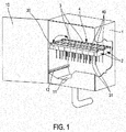
figure 1 représente un dispositif automatique de désinfection de porte-instruments rotatifs, comprenant des dispositifs de modules selon l'invention. - la
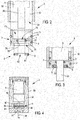
figure 2 représente une vue schématique partielle en coupe et en éclaté d'un dispositif de module selon l'invention. - la
figure 3 représente une vue schématique partielle en coupe du même dispositif de module. - la
figure 4 représente une vue schématique et en coupe d'une autre solution au problème posé.
- the
figure 1 represents an automatic device for disinfecting rotary instrument holders, comprising module devices according to the invention. - the
figure 2 is a partial schematic sectional view and exploded of a module device according to the invention. - the
figure 3 is a partial schematic sectional view of the same module device. - the
figure 4 represents a schematic view in section of another solution to the problem.
En référence à la
Chaque module 3 comporte un bloc 30, en l'occurrence de forme cubique, duquel font saillie un nez de fixation d'une pièce à main, et des rampes 31 munies trous de pulvérisation.Each
Enfin, l'enceinte 1 comporte un fond 11 en forme de trémie pour permettre de la collecte des fluides après usage. De manière avantageuse, l'enceinte 1 est munie de rampes d'aspersion 12, dont une seule est visible sur la
En référence maintenant aux
Sur ces
Le couvercle 6 qui est destiné à être engagé dans l'ouverture 32, est composé de deux pièces 7 et 8 assemblables l'une à l'autre.The lid 6 which is intended to be engaged in the opening 32, is composed of two
La pièce 7 se présente sous la forme générale d'un tube d'un diamètre extérieur lui permettant d'être introduite étroitement dans l'ouverture 33, l'étanchéité avec le bloc 30 étant réalisée au moyen d'un système de joint, comprenant en l'occurrence, non limitativement, deux joints toriques J, disposés chacun dans une gorge périphérique 70 pratiquée dans la paroi extérieure 71 de la pièce 7.The
La pièce 7 comporte intérieurement une cloison 72 qui délimite d'un côté un logement 73 destiné à coiffer la partie extrême 51 du moteur 5 de laquelle fait saillie l'arbre menant 50, et de l'autre une cavité 74 destinée à loger la pièce 8.The
La cloison 72 est percée centralement d'un alésage 75 pour le passage étroit de l'arbre 50, dans la paroi intérieure 76 duquel est pratiquée une gorge périphérique 77 garnie d'un joint torique T.The
La pièce 8 se présente sous une forme annulaire, elle est d'épaisseur correspondant à la profondeur de la cavité 74, elle comporte d'une part une paroi extérieure 80 dans laquelle est creusée une cavité périphérique 81 logeant un joint S, permettant de réaliser l'étanchéité avec la paroi périphérique interne 78 de la cavité 74, et d'autre part un alésage central 82 dont le diamètre est ajusté à celui de l'arbre 50 en sorte de pouvoir réaliser une étanchéité par serrage glissant.The
Les assemblages de la pièce 8 à la pièce 7, et de la pièce 7 au bloc 30, au travers des emboîtements au travers des différents joints J, T et S, permet de garantir une parfaite coaxialité de l'arbre 50 et de l'alésage 82, sachant que par ailleurs, la position du moteur 5 est maintenue et stabilisée dans le bloc 30.The assemblies of the
En référence à la figure 9, on peut voir une autre solution au problème de l'étanchéité, utilisant le magnétisme.With reference to FIG. 9, another solution to the problem of sealing, using magnetism, can be seen.
On peut voir un module 3, comprenant un bloc 30 dans lequel sont pratiqués deux compartiments 34 et 35 dans le prolongement l'un de l'autre, et séparés par une paroi 36. Le compartiment 34 est entièrement hermétique et il loge le moteur 5, tandis que le compartiment 35 comporte un palier 37 supportant un arbre mené 38 qui fait saillie du bloc 30, et dont la partie extérieure à ce bloc 30 est destinée à recevoir un porte-instruments rotatif.We can see a
On notera que le compartiment 35 peut être créé dans le bloc 30, ou bien venir de l'adjonction au bloc 30 d'un élément rapporté.Note that the
L'arbre menant 50 du moteur 5 et l'arbre mené 38, sont liés par l'intermédiaire d'une liaison magnétique 9, laquelle comprend un volant 90 solidaire de l'arbre menant 50 et un plateau 91 duquel est solidaire l'arbre mené 38, le volant 90 et le plateau 91 étant en regard l'un de l'autre, de part et d'autre de la paroi 36, et munis de moyens magnétiques tels que des aimants, non représentés.The
La paroi 36 est bien entendu configurée pour ne pas entraver le champs magnétique créé, et permettre l'entraînement du plateau 91 et donc de l'arbre mené 38, elle est notamment de faible épaisseur.The
Claims (5)
- Module device (3) for supporting a rotary instrument-holder, intended to be provided with other analogous modules (3) on an automatic device for disinfecting and maintaining a rotary instrument-holder, comprising an enclosure (1), said enclosure (1) enclosing a plurality of modules (3) juxtaposed to and made integral with at least one receiving means (4) arranged inside said enclosure (1), and wherein the modules (3) comprise, on the one hand, means for fixing rotary instrument-holders as well as connecting means capable of permitting the diffusion, in the rotary instrument-holder and between the modules (3), of cleaning and/or disinfecting and/or lubricating fluids; and, on the other hand, a motor (5) capable of causing the rotary instrument-holder to rotate, said motor (5) being accommodated in a cavity (32) formed in said module (3), closed by a cover (6) through which passes the driving shaft (50) of said motor (5), said cover (6) consisting of the assembly of at least two concentric parts (7, 8), wherein a first part (7) having a tubular shape is intended to be inserted into the opening (33) of said cavity (32) and provided, on the one hand, with a peripheral seal system (J) capable of ensuring the tightness with said module (3) and, on the other hand, an internal seal system (T) capable of ensuring the tightness with said shaft (50), and a ring-shaped second part (8) inserted into a peripheral rabbet (74) is formed internally in said first part (7) on the outlet side of said shaft (50) and comprises, in addition to a peripheral seal system (S) capable of ensuring the tightness with said first part (7), a central bore (75) intended to be crossed as tightly as possible by said shaft (50), to this end the latter has dimensions adjusted to ensure the tightness by slidable clamping.
- Module device (3) according to claim 1, wherein the motor (5) is covered with a sheath made of heat-shrinkable material.
- Module device according to claim 1 or claim 2, wherein the interior of the cavity (32), in which the motor (5) is placed, is filled with a filler material.
- Module device according to claim 3, wherein the filler material consists of a semi-rigid resin or a gel.
- Automatic device for disinfecting and maintaining a rotary instrument-holder, wherein it is provided with modules (3) according to any one of claims 1 to 4.
Applications Claiming Priority (1)
| Application Number | Priority Date | Filing Date | Title |
|---|---|---|---|
| FR1658597A FR3055804B1 (en) | 2016-09-14 | 2016-09-14 | ROTARY INSTRUMENT HOLDER MODULE DEVICE |
Publications (2)
| Publication Number | Publication Date |
|---|---|
| EP3295965A1 EP3295965A1 (en) | 2018-03-21 |
| EP3295965B1 true EP3295965B1 (en) | 2019-10-30 |
Family
ID=57590613
Family Applications (1)
| Application Number | Title | Priority Date | Filing Date |
|---|---|---|---|
| EP17190501.1A Active EP3295965B1 (en) | 2016-09-14 | 2017-09-12 | Device of a support module for rotary instrument holder |
Country Status (3)
| Country | Link |
|---|---|
| EP (1) | EP3295965B1 (en) |
| ES (1) | ES2770133T3 (en) |
| FR (1) | FR3055804B1 (en) |
Cited By (1)
| Publication number | Priority date | Publication date | Assignee | Title |
|---|---|---|---|---|
| FR3142092A1 (en) * | 2022-11-22 | 2024-05-24 | Vr2M | Method for maintaining dynamic instrument holders and device implementing such a method |
Families Citing this family (1)
| Publication number | Priority date | Publication date | Assignee | Title |
|---|---|---|---|---|
| CN111227976B (en) * | 2020-01-16 | 2021-05-11 | 青岛市口腔医院 | Oral cavity instrument is placed and is taken rack |
Family Cites Families (4)
| Publication number | Priority date | Publication date | Assignee | Title |
|---|---|---|---|---|
| US4990087A (en) * | 1990-01-26 | 1991-02-05 | Rocchis Louis G De | Dental tool maintenance apparatus and method |
| DE19913946B4 (en) * | 1999-03-26 | 2011-05-12 | Kaltenbach & Voigt Gmbh & Co. Kg | Care device for a medical or dental handpiece |
| DK1749502T3 (en) * | 2005-08-05 | 2008-07-07 | W & H Dentalwerk Buermoos Gmbh | Maintenance or cleaning apparatus for medical instruments |
| FR2958852B1 (en) * | 2010-04-14 | 2012-06-01 | Nnie Plus | AUTOMATIC DEVICE FOR DISINFECTING SURGICAL ENGINES. |
-
2016
- 2016-09-14 FR FR1658597A patent/FR3055804B1/en not_active Expired - Fee Related
-
2017
- 2017-09-12 EP EP17190501.1A patent/EP3295965B1/en active Active
- 2017-09-12 ES ES17190501T patent/ES2770133T3/en active Active
Non-Patent Citations (1)
| Title |
|---|
| None * |
Cited By (2)
| Publication number | Priority date | Publication date | Assignee | Title |
|---|---|---|---|---|
| FR3142092A1 (en) * | 2022-11-22 | 2024-05-24 | Vr2M | Method for maintaining dynamic instrument holders and device implementing such a method |
| WO2024110421A1 (en) * | 2022-11-22 | 2024-05-30 | Vr2M | Method for maintaining an instrument handpiece, and device for carrying out said method |
Also Published As
| Publication number | Publication date |
|---|---|
| FR3055804B1 (en) | 2018-09-28 |
| FR3055804A1 (en) | 2018-03-16 |
| ES2770133T3 (en) | 2020-06-30 |
| EP3295965A1 (en) | 2018-03-21 |
Similar Documents
| Publication | Publication Date | Title |
|---|---|---|
| EP3295965B1 (en) | Device of a support module for rotary instrument holder | |
| FR2985107A1 (en) | ELECTRIC MACHINE, IN PARTICULAR FOR MOTOR VEHICLE | |
| FR2998328A1 (en) | SEALED ENCLOSURE COMPRISING AN OPENING AND CLOSING CONTROL MECHANISM FOR A TRANSFER DEVICE SEALED BETWEEN TWO CLOSED VOLUMES | |
| FR2678741A1 (en) | ZOOM LENS BARRIER FOR WATERPROOF AND / OR WATERPROOF CAMERA. | |
| FR2864442A1 (en) | DENTAL HANDPIECE WITH A SINGLE PIECE BODY COMPRISING AN ELECTRICAL AND ELASTIC BONDING MEMBER BETWEEN THE MECHANICAL TRANSMISSION BODIES AND THE HEAD OF THE INSTRUMENT | |
| FR3072990A1 (en) | LOCK AND KEY FOR THIS LOCK | |
| FR2958852A1 (en) | AUTOMATIC DEVICE FOR DISINFECTING SURGICAL ENGINES. | |
| FR2728777A1 (en) | Instrument for removing skin calluses | |
| JP2012116323A (en) | Mirror device for vehicle | |
| FR3072989B1 (en) | ELECTRONIC KEY FOR AN ELECTRONIC LOCK | |
| FR2985631A1 (en) | HOUSING FOR ELECTRONIC DEVICE | |
| FR2880598A1 (en) | PROJECTOR COMPRISING A CORRECTION ACTUATOR WITH REDUCED LONGITUDINAL SIZE. | |
| CA2670641C (en) | Assembly device for a filter designed with a barrier to rotation | |
| CH706352B1 (en) | Timepiece including a winding mechanism with contactless torque transfer. | |
| FR3066312B1 (en) | STARTER CONTACTOR COMPRISING A SEALING DEVICE, AND STARTER COMPRISING SUCH A CONTACTOR | |
| FR2821761A1 (en) | PLUSH OR DOLL-LIKE TOY COMPRISING AN ADDITIONAL ATTENTION AWAKENING DEVICE | |
| EP1054199A1 (en) | Motorised valve for a selective distribution assembly for circulating fluid | |
| CH709425B1 (en) | Timepiece box with moving indicator controlled by a telescope. | |
| WO2015113669A1 (en) | Timepiece with bezel-operated mobile indicator | |
| FR3072991A1 (en) | ASSEMBLY COMPRISING AN ELECTRONIC LOCK AND AN ELECTRONIC KEY | |
| CH711683B1 (en) | Watchmaking set consisting of a watch and an additional winding mechanism. | |
| FR3056465A1 (en) | ACTUATOR FOR AIR INTAKE CONTROL DEVICE FOR MOTOR VEHICLE | |
| CH709188A2 (en) | Box timepiece mobile indicator controlled by a bezel. | |
| FR3094343A1 (en) | Drone comprising a base and a suspended plate | |
| CH707984A2 (en) | reassembly function housing for self-winding watch. |
Legal Events
| Date | Code | Title | Description |
|---|---|---|---|
| PUAI | Public reference made under article 153(3) epc to a published international application that has entered the european phase |
Free format text: ORIGINAL CODE: 0009012 |
|
| STAA | Information on the status of an ep patent application or granted ep patent |
Free format text: STATUS: THE APPLICATION HAS BEEN PUBLISHED |
|
| AK | Designated contracting states |
Kind code of ref document: A1 Designated state(s): AL AT BE BG CH CY CZ DE DK EE ES FI FR GB GR HR HU IE IS IT LI LT LU LV MC MK MT NL NO PL PT RO RS SE SI SK SM TR |
|
| AX | Request for extension of the european patent |
Extension state: BA ME |
|
| STAA | Information on the status of an ep patent application or granted ep patent |
Free format text: STATUS: REQUEST FOR EXAMINATION WAS MADE |
|
| 17P | Request for examination filed |
Effective date: 20180917 |
|
| RBV | Designated contracting states (corrected) |
Designated state(s): AL AT BE BG CH CY CZ DE DK EE ES FI FR GB GR HR HU IE IS IT LI LT LU LV MC MK MT NL NO PL PT RO RS SE SI SK SM TR |
|
| GRAP | Despatch of communication of intention to grant a patent |
Free format text: ORIGINAL CODE: EPIDOSNIGR1 |
|
| STAA | Information on the status of an ep patent application or granted ep patent |
Free format text: STATUS: GRANT OF PATENT IS INTENDED |
|
| INTG | Intention to grant announced |
Effective date: 20190508 |
|
| GRAS | Grant fee paid |
Free format text: ORIGINAL CODE: EPIDOSNIGR3 |
|
| GRAA | (expected) grant |
Free format text: ORIGINAL CODE: 0009210 |
|
| STAA | Information on the status of an ep patent application or granted ep patent |
Free format text: STATUS: THE PATENT HAS BEEN GRANTED |
|
| AK | Designated contracting states |
Kind code of ref document: B1 Designated state(s): AL AT BE BG CH CY CZ DE DK EE ES FI FR GB GR HR HU IE IS IT LI LT LU LV MC MK MT NL NO PL PT RO RS SE SI SK SM TR |
|
| REG | Reference to a national code |
Ref country code: GB Ref legal event code: FG4D Free format text: NOT ENGLISH |
|
| REG | Reference to a national code |
Ref country code: CH Ref legal event code: EP |
|
| REG | Reference to a national code |
Ref country code: AT Ref legal event code: REF Ref document number: 1195454 Country of ref document: AT Kind code of ref document: T Effective date: 20191115 |
|
| REG | Reference to a national code |
Ref country code: DE Ref legal event code: R096 Ref document number: 602017008179 Country of ref document: DE |
|
| REG | Reference to a national code |
Ref country code: IE Ref legal event code: FG4D Free format text: LANGUAGE OF EP DOCUMENT: FRENCH |
|
| REG | Reference to a national code |
Ref country code: SE Ref legal event code: TRGR |
|
| REG | Reference to a national code |
Ref country code: LT Ref legal event code: MG4D |
|
| PG25 | Lapsed in a contracting state [announced via postgrant information from national office to epo] |
Ref country code: NL Free format text: LAPSE BECAUSE OF FAILURE TO SUBMIT A TRANSLATION OF THE DESCRIPTION OR TO PAY THE FEE WITHIN THE PRESCRIBED TIME-LIMIT Effective date: 20191030 Ref country code: PT Free format text: LAPSE BECAUSE OF FAILURE TO SUBMIT A TRANSLATION OF THE DESCRIPTION OR TO PAY THE FEE WITHIN THE PRESCRIBED TIME-LIMIT Effective date: 20200302 Ref country code: BG Free format text: LAPSE BECAUSE OF FAILURE TO SUBMIT A TRANSLATION OF THE DESCRIPTION OR TO PAY THE FEE WITHIN THE PRESCRIBED TIME-LIMIT Effective date: 20200130 Ref country code: NO Free format text: LAPSE BECAUSE OF FAILURE TO SUBMIT A TRANSLATION OF THE DESCRIPTION OR TO PAY THE FEE WITHIN THE PRESCRIBED TIME-LIMIT Effective date: 20200130 Ref country code: LT Free format text: LAPSE BECAUSE OF FAILURE TO SUBMIT A TRANSLATION OF THE DESCRIPTION OR TO PAY THE FEE WITHIN THE PRESCRIBED TIME-LIMIT Effective date: 20191030 Ref country code: FI Free format text: LAPSE BECAUSE OF FAILURE TO SUBMIT A TRANSLATION OF THE DESCRIPTION OR TO PAY THE FEE WITHIN THE PRESCRIBED TIME-LIMIT Effective date: 20191030 Ref country code: LV Free format text: LAPSE BECAUSE OF FAILURE TO SUBMIT A TRANSLATION OF THE DESCRIPTION OR TO PAY THE FEE WITHIN THE PRESCRIBED TIME-LIMIT Effective date: 20191030 Ref country code: PL Free format text: LAPSE BECAUSE OF FAILURE TO SUBMIT A TRANSLATION OF THE DESCRIPTION OR TO PAY THE FEE WITHIN THE PRESCRIBED TIME-LIMIT Effective date: 20191030 Ref country code: GR Free format text: LAPSE BECAUSE OF FAILURE TO SUBMIT A TRANSLATION OF THE DESCRIPTION OR TO PAY THE FEE WITHIN THE PRESCRIBED TIME-LIMIT Effective date: 20200131 |
|
| REG | Reference to a national code |
Ref country code: NL Ref legal event code: MP Effective date: 20191030 |
|
| PG25 | Lapsed in a contracting state [announced via postgrant information from national office to epo] |
Ref country code: RS Free format text: LAPSE BECAUSE OF FAILURE TO SUBMIT A TRANSLATION OF THE DESCRIPTION OR TO PAY THE FEE WITHIN THE PRESCRIBED TIME-LIMIT Effective date: 20191030 Ref country code: HR Free format text: LAPSE BECAUSE OF FAILURE TO SUBMIT A TRANSLATION OF THE DESCRIPTION OR TO PAY THE FEE WITHIN THE PRESCRIBED TIME-LIMIT Effective date: 20191030 Ref country code: IS Free format text: LAPSE BECAUSE OF FAILURE TO SUBMIT A TRANSLATION OF THE DESCRIPTION OR TO PAY THE FEE WITHIN THE PRESCRIBED TIME-LIMIT Effective date: 20200229 |
|
| PG25 | Lapsed in a contracting state [announced via postgrant information from national office to epo] |
Ref country code: AL Free format text: LAPSE BECAUSE OF FAILURE TO SUBMIT A TRANSLATION OF THE DESCRIPTION OR TO PAY THE FEE WITHIN THE PRESCRIBED TIME-LIMIT Effective date: 20191030 |
|
| REG | Reference to a national code |
Ref country code: ES Ref legal event code: FG2A Ref document number: 2770133 Country of ref document: ES Kind code of ref document: T3 Effective date: 20200630 |
|
| PG25 | Lapsed in a contracting state [announced via postgrant information from national office to epo] |
Ref country code: RO Free format text: LAPSE BECAUSE OF FAILURE TO SUBMIT A TRANSLATION OF THE DESCRIPTION OR TO PAY THE FEE WITHIN THE PRESCRIBED TIME-LIMIT Effective date: 20191030 Ref country code: CZ Free format text: LAPSE BECAUSE OF FAILURE TO SUBMIT A TRANSLATION OF THE DESCRIPTION OR TO PAY THE FEE WITHIN THE PRESCRIBED TIME-LIMIT Effective date: 20191030 Ref country code: EE Free format text: LAPSE BECAUSE OF FAILURE TO SUBMIT A TRANSLATION OF THE DESCRIPTION OR TO PAY THE FEE WITHIN THE PRESCRIBED TIME-LIMIT Effective date: 20191030 Ref country code: DK Free format text: LAPSE BECAUSE OF FAILURE TO SUBMIT A TRANSLATION OF THE DESCRIPTION OR TO PAY THE FEE WITHIN THE PRESCRIBED TIME-LIMIT Effective date: 20191030 |
|
| REG | Reference to a national code |
Ref country code: DE Ref legal event code: R097 Ref document number: 602017008179 Country of ref document: DE |
|
| PG25 | Lapsed in a contracting state [announced via postgrant information from national office to epo] |
Ref country code: SM Free format text: LAPSE BECAUSE OF FAILURE TO SUBMIT A TRANSLATION OF THE DESCRIPTION OR TO PAY THE FEE WITHIN THE PRESCRIBED TIME-LIMIT Effective date: 20191030 Ref country code: SK Free format text: LAPSE BECAUSE OF FAILURE TO SUBMIT A TRANSLATION OF THE DESCRIPTION OR TO PAY THE FEE WITHIN THE PRESCRIBED TIME-LIMIT Effective date: 20191030 |
|
| PLBE | No opposition filed within time limit |
Free format text: ORIGINAL CODE: 0009261 |
|
| STAA | Information on the status of an ep patent application or granted ep patent |
Free format text: STATUS: NO OPPOSITION FILED WITHIN TIME LIMIT |
|
| 26N | No opposition filed |
Effective date: 20200731 |
|
| PG25 | Lapsed in a contracting state [announced via postgrant information from national office to epo] |
Ref country code: SI Free format text: LAPSE BECAUSE OF FAILURE TO SUBMIT A TRANSLATION OF THE DESCRIPTION OR TO PAY THE FEE WITHIN THE PRESCRIBED TIME-LIMIT Effective date: 20191030 |
|
| REG | Reference to a national code |
Ref country code: BE Ref legal event code: MM Effective date: 20200930 |
|
| PG25 | Lapsed in a contracting state [announced via postgrant information from national office to epo] |
Ref country code: LU Free format text: LAPSE BECAUSE OF NON-PAYMENT OF DUE FEES Effective date: 20200912 |
|
| PG25 | Lapsed in a contracting state [announced via postgrant information from national office to epo] |
Ref country code: BE Free format text: LAPSE BECAUSE OF NON-PAYMENT OF DUE FEES Effective date: 20200930 Ref country code: IE Free format text: LAPSE BECAUSE OF NON-PAYMENT OF DUE FEES Effective date: 20200912 |
|
| PG25 | Lapsed in a contracting state [announced via postgrant information from national office to epo] |
Ref country code: TR Free format text: LAPSE BECAUSE OF FAILURE TO SUBMIT A TRANSLATION OF THE DESCRIPTION OR TO PAY THE FEE WITHIN THE PRESCRIBED TIME-LIMIT Effective date: 20191030 Ref country code: MT Free format text: LAPSE BECAUSE OF FAILURE TO SUBMIT A TRANSLATION OF THE DESCRIPTION OR TO PAY THE FEE WITHIN THE PRESCRIBED TIME-LIMIT Effective date: 20191030 Ref country code: CY Free format text: LAPSE BECAUSE OF FAILURE TO SUBMIT A TRANSLATION OF THE DESCRIPTION OR TO PAY THE FEE WITHIN THE PRESCRIBED TIME-LIMIT Effective date: 20191030 |
|
| PG25 | Lapsed in a contracting state [announced via postgrant information from national office to epo] |
Ref country code: MK Free format text: LAPSE BECAUSE OF FAILURE TO SUBMIT A TRANSLATION OF THE DESCRIPTION OR TO PAY THE FEE WITHIN THE PRESCRIBED TIME-LIMIT Effective date: 20191030 Ref country code: MC Free format text: LAPSE BECAUSE OF FAILURE TO SUBMIT A TRANSLATION OF THE DESCRIPTION OR TO PAY THE FEE WITHIN THE PRESCRIBED TIME-LIMIT Effective date: 20191030 |
|
| REG | Reference to a national code |
Ref country code: AT Ref legal event code: UEP Ref document number: 1195454 Country of ref document: AT Kind code of ref document: T Effective date: 20191030 |
|
| PGFP | Annual fee paid to national office [announced via postgrant information from national office to epo] |
Ref country code: IT Payment date: 20230927 Year of fee payment: 7 Ref country code: AT Payment date: 20230927 Year of fee payment: 7 |
|
| PGFP | Annual fee paid to national office [announced via postgrant information from national office to epo] |
Ref country code: SE Payment date: 20230926 Year of fee payment: 7 |
|
| PGFP | Annual fee paid to national office [announced via postgrant information from national office to epo] |
Ref country code: ES Payment date: 20231002 Year of fee payment: 7 |
|
| PGFP | Annual fee paid to national office [announced via postgrant information from national office to epo] |
Ref country code: CH Payment date: 20231001 Year of fee payment: 7 |
|
| PGFP | Annual fee paid to national office [announced via postgrant information from national office to epo] |
Ref country code: DE Payment date: 20240919 Year of fee payment: 8 |
|
| PGFP | Annual fee paid to national office [announced via postgrant information from national office to epo] |
Ref country code: GB Payment date: 20240918 Year of fee payment: 8 |
|
| PGFP | Annual fee paid to national office [announced via postgrant information from national office to epo] |
Ref country code: FR Payment date: 20240918 Year of fee payment: 8 |