EP3295759B1 - Method for link quality based relay selection, apparatus and computer-readable medium - Google Patents
Method for link quality based relay selection, apparatus and computer-readable medium Download PDFInfo
- Publication number
- EP3295759B1 EP3295759B1 EP16718069.4A EP16718069A EP3295759B1 EP 3295759 B1 EP3295759 B1 EP 3295759B1 EP 16718069 A EP16718069 A EP 16718069A EP 3295759 B1 EP3295759 B1 EP 3295759B1
- Authority
- EP
- European Patent Office
- Prior art keywords
- link quality
- potential relay
- relay
- link
- remote
- Prior art date
- Legal status (The legal status is an assumption and is not a legal conclusion. Google has not performed a legal analysis and makes no representation as to the accuracy of the status listed.)
- Active
Links
- 238000000034 method Methods 0.000 title claims description 39
- 238000004891 communication Methods 0.000 claims description 49
- 238000005259 measurement Methods 0.000 claims description 21
- 238000012545 processing Methods 0.000 description 26
- 230000006870 function Effects 0.000 description 21
- 238000010586 diagram Methods 0.000 description 20
- 230000005540 biological transmission Effects 0.000 description 19
- 238000005516 engineering process Methods 0.000 description 10
- 238000001228 spectrum Methods 0.000 description 9
- 239000000969 carrier Substances 0.000 description 7
- 230000008569 process Effects 0.000 description 7
- 230000003595 spectral effect Effects 0.000 description 6
- 238000012937 correction Methods 0.000 description 5
- 238000007726 management method Methods 0.000 description 5
- 230000011664 signaling Effects 0.000 description 5
- 238000003860 storage Methods 0.000 description 5
- 230000006837 decompression Effects 0.000 description 4
- 238000013507 mapping Methods 0.000 description 4
- 230000001413 cellular effect Effects 0.000 description 3
- 230000006835 compression Effects 0.000 description 3
- 238000007906 compression Methods 0.000 description 3
- 238000013461 design Methods 0.000 description 3
- 238000001514 detection method Methods 0.000 description 3
- 238000012546 transfer Methods 0.000 description 3
- 238000013459 approach Methods 0.000 description 2
- 125000004122 cyclic group Chemical group 0.000 description 2
- 230000001419 dependent effect Effects 0.000 description 2
- 238000011982 device technology Methods 0.000 description 2
- 238000012986 modification Methods 0.000 description 2
- 230000004048 modification Effects 0.000 description 2
- 230000010363 phase shift Effects 0.000 description 2
- 238000012913 prioritisation Methods 0.000 description 2
- 230000011218 segmentation Effects 0.000 description 2
- 238000012795 verification Methods 0.000 description 2
- 230000002776 aggregation Effects 0.000 description 1
- 238000004220 aggregation Methods 0.000 description 1
- 238000003491 array Methods 0.000 description 1
- 230000010267 cellular communication Effects 0.000 description 1
- 239000003795 chemical substances by application Substances 0.000 description 1
- 210000001520 comb Anatomy 0.000 description 1
- 238000009826 distribution Methods 0.000 description 1
- 230000009977 dual effect Effects 0.000 description 1
- 239000000284 extract Substances 0.000 description 1
- 230000000977 initiatory effect Effects 0.000 description 1
- 230000007774 longterm Effects 0.000 description 1
- 239000011159 matrix material Substances 0.000 description 1
- 230000007246 mechanism Effects 0.000 description 1
- 230000003287 optical effect Effects 0.000 description 1
- 238000005457 optimization Methods 0.000 description 1
- 230000002093 peripheral effect Effects 0.000 description 1
- 230000001360 synchronised effect Effects 0.000 description 1
- 230000007704 transition Effects 0.000 description 1
- 238000005303 weighing Methods 0.000 description 1
Images


Classifications
-
- H—ELECTRICITY
- H04—ELECTRIC COMMUNICATION TECHNIQUE
- H04W—WIRELESS COMMUNICATION NETWORKS
- H04W48/00—Access restriction; Network selection; Access point selection
- H04W48/17—Selecting a data network PoA [Point of Attachment]
-
- H—ELECTRICITY
- H04—ELECTRIC COMMUNICATION TECHNIQUE
- H04W—WIRELESS COMMUNICATION NETWORKS
- H04W40/00—Communication routing or communication path finding
- H04W40/02—Communication route or path selection, e.g. power-based or shortest path routing
- H04W40/22—Communication route or path selection, e.g. power-based or shortest path routing using selective relaying for reaching a BTS [Base Transceiver Station] or an access point
-
- H—ELECTRICITY
- H04—ELECTRIC COMMUNICATION TECHNIQUE
- H04W—WIRELESS COMMUNICATION NETWORKS
- H04W76/00—Connection management
- H04W76/10—Connection setup
- H04W76/14—Direct-mode setup
-
- H—ELECTRICITY
- H04—ELECTRIC COMMUNICATION TECHNIQUE
- H04W—WIRELESS COMMUNICATION NETWORKS
- H04W24/00—Supervisory, monitoring or testing arrangements
- H04W24/10—Scheduling measurement reports ; Arrangements for measurement reports
-
- H—ELECTRICITY
- H04—ELECTRIC COMMUNICATION TECHNIQUE
- H04B—TRANSMISSION
- H04B7/00—Radio transmission systems, i.e. using radiation field
- H04B7/14—Relay systems
- H04B7/15—Active relay systems
- H04B7/155—Ground-based stations
-
- H—ELECTRICITY
- H04—ELECTRIC COMMUNICATION TECHNIQUE
- H04W—WIRELESS COMMUNICATION NETWORKS
- H04W40/00—Communication routing or communication path finding
- H04W40/02—Communication route or path selection, e.g. power-based or shortest path routing
- H04W40/12—Communication route or path selection, e.g. power-based or shortest path routing based on transmission quality or channel quality
-
- H—ELECTRICITY
- H04—ELECTRIC COMMUNICATION TECHNIQUE
- H04W—WIRELESS COMMUNICATION NETWORKS
- H04W48/00—Access restriction; Network selection; Access point selection
- H04W48/08—Access restriction or access information delivery, e.g. discovery data delivery
- H04W48/12—Access restriction or access information delivery, e.g. discovery data delivery using downlink control channel
-
- H—ELECTRICITY
- H04—ELECTRIC COMMUNICATION TECHNIQUE
- H04W—WIRELESS COMMUNICATION NETWORKS
- H04W8/00—Network data management
- H04W8/005—Discovery of network devices, e.g. terminals
-
- H—ELECTRICITY
- H04—ELECTRIC COMMUNICATION TECHNIQUE
- H04W—WIRELESS COMMUNICATION NETWORKS
- H04W88/00—Devices specially adapted for wireless communication networks, e.g. terminals, base stations or access point devices
- H04W88/02—Terminal devices
- H04W88/04—Terminal devices adapted for relaying to or from another terminal or user
-
- Y—GENERAL TAGGING OF NEW TECHNOLOGICAL DEVELOPMENTS; GENERAL TAGGING OF CROSS-SECTIONAL TECHNOLOGIES SPANNING OVER SEVERAL SECTIONS OF THE IPC; TECHNICAL SUBJECTS COVERED BY FORMER USPC CROSS-REFERENCE ART COLLECTIONS [XRACs] AND DIGESTS
- Y02—TECHNOLOGIES OR APPLICATIONS FOR MITIGATION OR ADAPTATION AGAINST CLIMATE CHANGE
- Y02D—CLIMATE CHANGE MITIGATION TECHNOLOGIES IN INFORMATION AND COMMUNICATION TECHNOLOGIES [ICT], I.E. INFORMATION AND COMMUNICATION TECHNOLOGIES AIMING AT THE REDUCTION OF THEIR OWN ENERGY USE
- Y02D30/00—Reducing energy consumption in communication networks
- Y02D30/70—Reducing energy consumption in communication networks in wireless communication networks
Definitions
- the present disclosure relates generally to communication systems, and more particularly, to relay selection in communication systems.
- Wireless communication systems are widely deployed to provide various telecommunication services such as telephony, video, data, messaging, and broadcasts.
- Typical wireless communication systems may employ multiple-access technologies capable of supporting communication with multiple users by sharing available system resources. Examples of such multiple-access technologies include code division multiple access (CDMA) systems, time division multiple access (TDMA) systems, frequency division multiple access (FDMA) systems, orthogonal frequency division multiple access (OFDMA) systems, single-carrier frequency division multiple access (SC-FDMA) systems, and time division synchronous code division multiple access (TD-SCDMA) systems.
- CDMA code division multiple access
- TDMA time division multiple access
- FDMA frequency division multiple access
- OFDMA orthogonal frequency division multiple access
- SC-FDMA single-carrier frequency division multiple access
- TD-SCDMA time division synchronous code division multiple access
- LTE Long Term Evolution
- UMTS Universal Mobile Telecommunications System
- 3GPP Third Generation Partnership Project
- LTE is designed to support mobile broadband access through improved spectral efficiency, lowered costs, and improved services using OFDMA on the downlink, SC-FDMA on the uplink, and multiple-input multiple-output (MIMO) antenna technology.
- MIMO multiple-input multiple-output
- LTE has been applied to develop a device-to-device technology that enables mobile devices and applications to passively discover and interact with the world around them.
- this device-to-device technology may be referred to as LTE Direct (LTE-D).
- LTE-D LTE Direct
- UE user equipment
- ProSe Proximity-Based Service
- WO 2014/153770 A1 relates to the reestablishment of communication with a network utilizing user equipment that serves as a relay.
- Ericsson “Measurements, Signaling and Selection Rules for Relay Discovery", R1-151767 relates to the relay discovery procedure from RANI perspective.
- Qualcomm Incorporated "Network coverage using L3-based UE-to-Network Relays”; R2-151510 relates to RAN aspects and enhancements to L3-based UE-to-Network relays.
- Qualcomm Incorporated “UE-to-Network Relay conclusions”; S2-150925 relates to UE-to-Network Relay operation, discovery and selection.
- US 2014/0171062 A1 relates to handling relay assistance.
- the present invention provides a method as defined by independent claim 1.
- the present invention provides an apparatus as defined by independent claim 12.
- the present invention provides a computer-readable medium as defined by independent claim 13.
- processors include microprocessors, microcontrollers, graphics processing units (GPUs), central processing units (CPUs), application processors, digital signal processors (DSPs), reduced instruction set computing (RISC) processors, systems on a chip (SoC), baseband processors, field programmable gate arrays (FPGAs), programmable logic devices (PLDs), state machines, gated logic, discrete hardware circuits, and other suitable hardware configured to perform the various functionality described throughout this disclosure.
- processors in the processing system may execute software.
- Software shall be construed broadly to mean instructions, instruction sets, code, code segments, program code, programs, subprograms, software components, applications, software applications, software packages, routines, subroutines, objects, executables, threads of execution, procedures, functions, etc., whether referred to as software, firmware, middleware, microcode, hardware description language, or otherwise.
- the functions described may be implemented in hardware, software, or any combination thereof. If implemented in software, the functions may be stored on or encoded as one or more instructions or code on a computer-readable medium.
- Computer-readable media includes computer storage media. Storage media may be any available media that can be accessed by a computer.
- such computer-readable media can comprise a random-access memory (RAM), a read-only memory (ROM), an electrically erasable programmable ROM (EEPROM), optical disk storage, magnetic disk storage, other magnetic storage devices, combinations of the aforementioned types of computer-readable media, or any other medium that can be used to store computer executable code in the form of instructions or data structures that can be accessed by a computer.
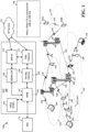
- FIG. 1 is a diagram illustrating an example of a wireless communications system and an access network 100.
- the wireless communications system (also referred to as a wireless wide area network (WWAN)) includes base stations 102, UEs 104, and an Evolved Packet Core (EPC) 160.
- the base stations 102 may include macro cells (high power cellular base station) and/or small cells (low power cellular base station).
- the macro cells include eNBs.
- the small cells include femtocells, picocells, and microcells.
- the base stations 102 interface with the EPC 160 through backhaul links 132 (e.g., S1 interface).
- the base stations 102 may perform one or more of the following functions: transfer of user data, radio channel ciphering and deciphering, integrity protection, header compression, mobility control functions (e.g., handover, dual connectivity), inter-cell interference coordination, connection setup and release, load balancing, distribution for non-access stratum (NAS) messages, NAS node selection, synchronization, radio access network (RAN) sharing, multimedia broadcast multicast service (MBMS), subscriber and equipment trace, RAN information management (RIM), paging, positioning, and delivery of warning messages.
- the base stations 102 may communicate directly or indirectly (e.g., through the EPC 160) with each other over backhaul links 134 (e.g., X2 interface).
- the backhaul links 134 may be wired or wireless.
- the base stations 102 may wirelessly communicate with the UEs 104. Each of the base stations 102 may provide communication coverage for a respective geographic coverage area 110. There may be overlapping geographic coverage areas 110. For example, the small cell 102' may have a coverage area 110' that overlaps the geographic coverage area 110 of one or more macro base stations 102.
- a network that includes both small cell and macro cells may be known as a heterogeneous network.
- a heterogeneous network may also include Home Evolved Node Bs (eNBs) (HeNBs), which may provide service to a restricted group known as a closed subscriber group (CSG).
- eNBs Home Evolved Node Bs
- CSG closed subscriber group
- the communication links 120 between the base stations 102 and the UEs 104 may include uplink (UL) (also referred to as reverse link) transmissions from a UE 104 to a base station 102 and/or downlink (DL) (also referred to as forward link) transmissions from a base station 102 to a UE 104.
- the communication links 120 may use MIMO antenna technology, including spatial multiplexing, beamforming, and/or transmit diversity.
- the communication links may be through one or more carriers.
- the base stations 102 / UEs 104 may use spectrum up to Y MHz (e.g., 5, 10, 15, 20 MHz) bandwidth per carrier allocated in a carrier aggregation of up to a total of Yx MHz (x component carriers) used for transmission in each direction.
- the carriers may or may not be adjacent to each other. Allocation of carriers may be asymmetric with respect to DL and UL (e.g., more or less carriers may be allocated for DL than for UL).
- the component carriers may include a primary component carrier and one or more secondary component carriers.
- a primary component carrier may be referred to as a primary cell (PCell) and a secondary component carrier may be referred to as a secondary cell (SCell).
- PCell primary cell
- SCell secondary cell
- the wireless communications system may further include a Wi-Fi access point 150 in communication with Wi-Fi stations (STAs) 152 via communication links 154 in a 5 GHz unlicensed frequency spectrum.
- STAs Wi-Fi stations
- communication links 154 in a 5 GHz unlicensed frequency spectrum.
- the STAs 152 / Wi-Fi access point 150 may perform a clear channel assessment (CCA) prior to communicating in order to determine whether the channel is available.
- CCA clear channel assessment
- the small cell 102' may operate in a licensed and/or an unlicensed frequency spectrum. When operating in an unlicensed frequency spectrum, the small cell 102' may employ LTE and use the same 5 GHz unlicensed frequency spectrum as used by the Wi-Fi access point 150. The small cell 102', employing LTE in an unlicensed frequency spectrum, may boost coverage to and/or increase capacity of the access network. LTE in an unlicensed spectrum may be referred to as LTE-unlicensed (LTE-U), licensed assisted access (LAA), or MuLTEfire.
- LTE-U LTE-unlicensed
- LAA licensed assisted access
- MuLTEfire MuLTEfire
- the EPC 160 may include a Mobility Management Entity (MME) 162, other MMEs 164, a Serving Gateway 166, a MBMS Gateway 168, a Broadcast Multicast Service Center (BM-SC) 170, and a Packet Data Network (PDN) Gateway 172.
- MME Mobility Management Entity
- BM-SC Broadcast Multicast Service Center
- PDN Packet Data Network
- the MME 162 may be in communication with a Home Subscriber Server (HSS) 174.
- HSS Home Subscriber Server
- the MME 162 is the control node that processes the signaling between the UEs 104 and the EPC 160.
- the MME 162 provides bearer and connection management. All user Internet protocol (IP) packets are transferred through the Serving Gateway 166, which itself is connected to the PDN Gateway 172.
- the PDN Gateway 172 provides UE IP address allocation as well as other functions.
- IP Internet protocol
- the PDN Gateway 172 and the BM-SC 170 are connected to the IP Services 176.
- the IP Services 176 may include the Internet, an intranet, an IP Multimedia Subsystem (IMS), a PS Streaming Service (PSS), and/or other IP services.
- the BM-SC 170 may provide functions for MBMS user service provisioning and delivery.
- the BM-SC 170 may serve as an entry point for content provider MBMS transmission, may be used to authorize and initiate MBMS Bearer Services within a public land mobile network (PLMN), and may be used to schedule MBMS transmissions.
- PLMN public land mobile network
- the MBMS Gateway 168 may be used to distribute MBMS traffic to the base stations 102 belonging to a Multicast Broadcast Single Frequency Network (MBSFN) area broadcasting a particular service, and may be responsible for session management (start/stop) and for collecting eMBMS related charging information.
- MMSFN Multicast Broadcast Single Frequency Network
- the base station may also be referred to as a Node B, evolved Node B (eNB), an access point, a base transceiver station, a radio base station, a radio transceiver, a transceiver function, a basic service set (BSS), an extended service set (ESS), or some other suitable terminology.
- the base station 102 provides an access point to the EPC 160 for a UE 104.
- Examples of UEs 104 include a cellular phone, a smart phone, a session initiation protocol (SIP) phone, a laptop, a personal digital assistant (PDA), a satellite radio, a global positioning system, a multimedia device, a video device, a digital audio player (e.g., MP3 player), a camera, a game console, a tablet, a smart device, a wearable device, or any other similar functioning device.
- SIP session initiation protocol
- PDA personal digital assistant
- satellite radio a global positioning system
- multimedia device e.g., a digital audio player (e.g., MP3 player), a camera, a game console, a tablet, a smart device, a wearable device, or any other similar functioning device.
- the UE 104 may also be referred to as a station, a mobile station, a subscriber station, a mobile unit, a subscriber unit, a wireless unit, a remote unit, a mobile device, a wireless device, a wireless communications device, a remote device, a mobile subscriber station, an access terminal, a mobile terminal, a wireless terminal, a remote terminal, a handset, a user agent, a mobile client, a client, or some other suitable terminology.
- the UE 104A may be configured to select a relay UE 104B to communicate with a base station 102, e.g., eNB (198).
- the UE 104A may have a communications link 156.
- the communications link 156 may be between the UE 104A and the UE 104B.
- the communications link 156 may include UL (also referred to as reverse link) transmissions from a UE 104A to the UE 104B which the UE 104B may transmit to the base station 102.
- the communications link 156 may include downlink (DL) (also referred to as forward link) transmissions from the UE 104B to a UE 104A.
- DL downlink
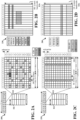
- FIG. 2A is a diagram 200 illustrating an example of a DL frame structure in LTE.
- FIG. 2B is a diagram 230 illustrating an example of channels within the DL frame structure in LTE.
- FIG. 2C is a diagram 250 illustrating an example of an UL frame structure in LTE.
- FIG. 2D is a diagram 280 illustrating an example of channels within the UL frame structure in LTE.
- Other wireless communication technologies may have a different frame structure and/or different channels.
- a frame (10 ms) may be divided into 10 equally sized subframes. Each subframe may include two consecutive time slots.
- a resource grid may be used to represent the two time slots, each time slot including one or more time concurrent resource blocks (RBs) (also referred to as physical RBs (PRBs)).
- RBs time concurrent resource blocks
- PRBs physical RBs
- the resource grid is divided into multiple resource elements (REs).
- REs resource elements
- an RB contains 12 consecutive subcarriers in the frequency domain and 7 consecutive symbols (for DL, OFDM symbols; for UL, SC-FDMA symbols) in the time domain, for a total of 84 REs.
- an RB contains 12 consecutive subcarriers in the frequency domain and 6 consecutive symbols in the time domain, for a total of 72 REs.
- the number of bits carried by each RE depends on the modulation scheme.
- the DL-RS may include cell-specific reference signals (CRS) (also sometimes called common RS), UE-specific reference signals (UE-RS), and channel state information reference signals (CSI-RS).
- CRS cell-specific reference signals
- UE-RS UE-specific reference signals
- CSI-RS channel state information reference signals
- FIG. 2A illustrates CRS for antenna ports 0, 1, 2, and 3 (indicated as R 0 , R 1 , R 2 , and R 3 , respectively), UE-RS for antenna port 5 (indicated as R 5 ), and CSI-RS for antenna port 15 (indicated as R).
- FIG. 2B illustrates an example of various channels within a DL subframe of a frame.
- the physical control format indicator channel (PCFICH) is within symbol 0 of slot 0, and carries a control format indicator (CFI) that indicates whether the physical downlink control channel (PDCCH) occupies 1, 2, or 3 symbols ( FIG. 2B illustrates a PDCCH that occupies 3 symbols).
- the PDCCH carries downlink control information (DCI) within one or more control channel elements (CCEs), each CCE including nine RE groups (REGs), each REG including four consecutive REs in an OFDM symbol.
- DCI downlink control information
- CCEs control channel elements
- Each CCE including nine RE groups (REGs), each REG including four consecutive REs in an OFDM symbol.
- a UE may be configured with a UE-specific enhanced PDCCH (ePDCCH) that also carries DCI.
- the ePDCCH may have 2, 4, or 8 RB pairs ( FIG. 2B shows two RB pairs, each subset including one RB pair).
- the physical hybrid automatic repeat request (ARQ) (HARQ) indicator channel (PHICH) is also within symbol 0 of slot 0 and carries the HARQ indicator (HI) that indicates HARQ acknowledgement (ACK) / negative ACK (NACK) feedback based on the physical uplink shared channel (PUSCH).
- the primary synchronization channel (PSCH) is within symbol 6 of slot 0 within subframes 0 and 5 of a frame, and carries a primary synchronization signal (PSS) that is used by a UE to determine subframe timing and a physical layer identity.
- the secondary synchronization channel is within symbol 5 of slot 0 within subframes 0 and 5 of a frame, and carries a secondary synchronization signal (SSS) that is used by a UE to determine a physical layer cell identity group number. Based on the physical layer identity and the physical layer cell identity group number, the UE can determine a physical cell identifier (PCI). Based on the PCI, the UE can determine the locations of the aforementioned DL-RS.
- the physical broadcast channel (PBCH) is within symbols 0, 1, 2, 3 of slot 1 of subframe 0 of a frame, and carries a master information block (MIB).
- the MIB provides a number of RBs in the DL system bandwidth, a PHICH configuration, and a system frame number (SFN).
- the physical downlink shared channel (PDSCH) carries user data, broadcast system information not transmitted through the PBCH such as system information blocks (SIBs), and paging messages.
- SIBs system information blocks
- some of the REs carry demodulation reference signals (DM-RS) for channel estimation at the eNB.
- the UE may additionally transmit sounding reference signals (SRS) in the last symbol of a subframe.
- SRS sounding reference signals
- the SRS may have a comb structure, and a UE may transmit SRS on one of the combs.
- the SRS may be used by an eNB for channel quality estimation to enable frequency-dependent scheduling on the UL.
- FIG. 2D illustrates an example of various channels within an UL subframe of a frame.
- a physical random access channel (PRACH) may be within one or more subframes within a frame based on the PRACH configuration.
- the PRACH may include six consecutive RB pairs within a subframe.
- PRACH physical random access channel
- the PRACH allows the UE to perform initial system access and achieve UL synchronization.
- a physical uplink control channel may be located on edges of the UL system bandwidth.
- the PUCCH carries uplink control information (UCI), such as scheduling requests, a channel quality indicator (CQI), a precoding matrix indicator (PMI), a rank indicator (RI), and HARQ ACK/NACK feedback.
- UCI uplink control information
- the PUSCH carries data, and may additionally be used to carry a buffer status report (BSR), a power headroom report (PHR), and/or UCI.
- BSR buffer status report
- PHR power headroom report
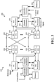
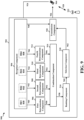
- FIG. 3 is a block diagram of an eNB 310 in communication with a UE 350 in an access network.
- IP packets from the EPC 160 may be provided to a controller/processor 375.
- the controller/processor 375 implements layer 3 and layer 2 functionality.
- Layer 3 includes a radio resource control (RRC) layer.
- Layer 2 includes a packet data convergence protocol (PDCP) layer, a radio link control (RLC) layer, and a medium access control (MAC) layer.
- RRC radio resource control
- PDCP packet data convergence protocol
- RLC radio link control
- MAC medium access control
- the controller/processor 375 provides RRC layer functionality associated with broadcasting of system information (e.g., MIB, SIBs), RRC connection control (e.g., RRC connection paging, RRC connection establishment, RRC connection modification, and RRC connection release), inter-radio access technology (RAT) mobility, and measurement configuration for UE measurement reporting; PDCP layer functionality associated with header compression / decompression, security (ciphering, deciphering, integrity protection, integrity verification), and handover support functions; RLC layer functionality associated with the transfer of upper layer packet data units (PDUs), error correction through ARQ, concatenation, segmentation, and reassembly of RLC service data units (SDUs), re-segmentation of RLC data PDUs, and reordering of RLC data PDUs; and MAC layer functionality associated with mapping between logical channels and transport channels, multiplexing of MAC SDUs onto transport blocks (TBs), demultiplexing of MAC SDUs from TBs, scheduling information reporting,
- the transmit (TX) processor 316 and the receive (RX) processor 370 implement layer 1 functionality associated with various signal processing functions.
- Layer 1 which includes a physical (PHY) layer, may include error detection on the transport channels, forward error correction (FEC) coding/decoding of the transport channels, interleaving, rate matching, mapping onto physical channels, modulation/demodulation of physical channels, and MIMO antenna processing.
- the TX processor 316 handles mapping to signal constellations based on various modulation schemes (e.g., binary phase-shift keying (BPSK), quadrature phase-shift keying (QPSK), M-phase-shift keying (M-PSK), M-quadrature amplitude modulation (M-QAM)).
- BPSK binary phase-shift keying
- QPSK quadrature phase-shift keying
- M-PSK M-phase-shift keying
- M-QAM M-quadrature amplitude modulation
- Each stream may then be mapped to an OFDM subcarrier, multiplexed with a reference signal (e.g., pilot) in the time and/or frequency domain, and then combined together using an Inverse Fast Fourier Transform (IFFT) to produce a physical channel carrying a time domain OFDM symbol stream.
- the OFDM stream is spatially precoded to produce multiple spatial streams.
- Channel estimates from a channel estimator 374 may be used to determine the coding and modulation scheme, as well as for spatial processing.
- the channel estimate may be derived from a reference signal and/or channel condition feedback transmitted by the UE 350.
- Each spatial stream may then be provided to a different antenna 320 via a separate transmitter 318TX.
- Each transmitter 318TX may modulate an RF carrier with a respective spatial stream for transmission.
- each receiver 354RX receives a signal through its respective antenna 352. Each receiver 354RX recovers information modulated onto an RF carrier and provides the information to the RX processor 356.
- the TX processor 368 and the RX processor 356 implement layer 1 functionality associated with various signal processing functions.
- the RX processor 356 may perform spatial processing on the information to recover any spatial streams destined for the UE 350. If multiple spatial streams are destined for the UE 350, they may be combined by the RX processor 356 into a single OFDM symbol stream.
- the RX processor 356 then converts the OFDM symbol stream from the time-domain to the frequency domain using a Fast Fourier Transform (FFT).
- FFT Fast Fourier Transform
- the symbols on each subcarrier, and the reference signal, are recovered and demodulated by determining the most likely signal constellation points transmitted by the eNB 310. These soft decisions may be based on channel estimates computed by the channel estimator 358. The soft decisions are then decoded and deinterleaved to recover the data and control signals that were originally transmitted by the eNB 310 on the physical channel. The data and control signals are then provided to the controller/processor 359, which implements layer 3 and layer 2 functionality.
- the controller/processor 359 can be associated with a memory 360 that stores program codes and data.
- the memory 360 may be referred to as a computer-readable medium.
- the controller/processor 359 provides demultiplexing between transport and logical channels, packet reassembly, deciphering, header decompression, and control signal processing to recover IP packets from the EPC 160.
- the controller/processor 359 is also responsible for error detection using an ACK and/or NACK protocol to support HARQ operations.
- the controller/processor 359 provides RRC layer functionality associated with system information (e.g., MIB, SIBs) acquisition, RRC connections, and measurement reporting; PDCP layer functionality associated with header compression / decompression, and security (ciphering, deciphering, integrity protection, integrity verification); RLC layer functionality associated with the transfer of upper layer PDUs, error correction through ARQ, concatenation, segmentation, and reassembly of RLC SDUs, re-segmentation of RLC data PDUs, and reordering of RLC data PDUs; and MAC layer functionality associated with mapping between logical channels and transport channels, multiplexing of MAC SDUs onto TBs, demuliplexing of MAC SDUs from TBs, scheduling information reporting, error correction through HARQ, priority handling, and logical channel prioritization.
- RRC layer functionality associated with system information (e.g., MIB, SIBs) acquisition, RRC connections, and measurement reporting
- PDCP layer functionality associated with header
- Channel estimates derived by a channel estimator 358 from a reference signal or feedback transmitted by the eNB 310 may be used by the TX processor 368 to select the appropriate coding and modulation schemes, and to facilitate spatial processing.
- the spatial streams generated by the TX processor 368 may be provided to different antenna 352 via separate transmitters 354TX. Each transmitter 354TX may modulate an RF carrier with a respective spatial stream for transmission.
- the UL transmission is processed at the eNB 310 in a manner similar to that described in connection with the receiver function at the UE 350.
- Each receiver 318RX receives a signal through its respective antenna 320.
- Each receiver 318RX recovers the information modulated onto an RF carrier and provides the information to an RX processor 370.
- the controller/processor 375 can be associated with a memory 376 that stores program codes and data.
- the memory 376 may be referred to as a computer-readable medium.
- the controller/processor 375 provides demultiplexing between transport and logical channels, packet reassembly, deciphering, header decompression, control signal processing to recover IP packets from the UE 350. IP packets from the controller/processor 375 may be provided to the EPC 160.
- the controller/processor 375 is also responsible for error detection using an ACK and/or NACK protocol to support HARQ operations.
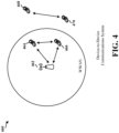
- FIG. 4 is a diagram of a device-to-device (D2D) communications system 460.
- the D2D communications system 460 includes a plurality of UEs 464, 466, 468, 470.
- the D2D communications system 460 may overlap with a cellular communications system, such as for example, a WWAN.
- Some of the UEs 464, 466, 468, 470 may communicate together in D2D communication using the DL/UL WWAN spectrum, some may communicate with the base station 462, and some may do both.
- the UEs 468, 470 are in D2D communication and the UEs 464, 466 are in D2D communication.
- the UEs 464, 466 are also communicating with the base station 462.
- the D2D communication may be through one or more sidelink channels, such as a physical sidelink broadcast channel (PSBCH), a physical sidelink discovery channel (PSDCH), a physical sidelink shared channel (PSSCH), and a physical sidelink control channel (PSCCH).
- sidelink channels such as a physical sidelink broadcast channel (PSBCH), a physical sidelink discovery channel (PSDCH), a physical sidelink shared channel (PSSCH), and a physical sidelink control channel (PSCCH).
- PSBCH physical sidelink broadcast channel
- PSDCH physical sidelink discovery channel
- PSSCH physical sidelink shared channel
- PSCCH physical sidelink control channel
- the exemplary methods and apparatuses discussed infra are applicable to any of a variety of wireless D2D communications systems, such as for example, a wireless device-to-device communication system based on FlashLinQ, WiMedia, Bluetooth, ZigBee, or Wi-Fi based on the IEEE 802.11 standard.
- a wireless device-to-device communication system based on FlashLinQ, WiMedia, Bluetooth, ZigBee, or Wi-Fi based on the IEEE 802.11 standard.
- the exemplary methods and apparatus are discussed within the context of LTE.
- one of ordinary skill in the art would understand that the exemplary methods and apparatuses are applicable more generally to a variety of other wireless device-to-device communication systems.
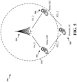
- FIG. 5 is a diagram illustrating an example system, 500 including a base station 502 (e.g., eNB), potential relay UEs 504, 506, a remote UE 508, and a coverage area 510 in accordance with some aspects of the present disclosure.
- a UE may move out of the coverage area 510.
- the coverage area 510 may be an area within communications range of the base station 502.
- a UE that moves out of the coverage area 510 may be referred to as a remote UE 508 because the remote UE 508 is not in the coverage area 510, i.e., the remote UE 508 is "remote" from the coverage area 510.
- the systems and methods described herein generally relate to selecting a relay node between the first potential relay UE 504, the second potential relay UE 506, or other available relay nodes.
- Two potential relay UE, e.g., the potential relay UEs 504, 506 are illustrated in FIG. 5 , however, it will be understood that the systems and methods described herein may be applied to any number of potential relay UEs 504, 506.
- the remote UE 508 may have to select the best relay UE among many candidate relay UEs (potential relay UEs 504, 506 are illustrated in FIG. 5 ). As illustrated in FIG. 5 , the potential relay UEs 504, 506 may be connected to the same base station 502. In other examples, however, candidate relay UEs are not connected to the same base station, as illustrated in FIG. 6 discussed below.
- the remote UE 508 may be considered to be outside of the coverage area 510 because signals to the base station are not detectable by the base station, signals from the base station are not detectable by the remote UE, or both. In some examples, the remote UE 508 may also be considered to be outside of the coverage area 510 because the signal quality of signals to the base station, the signal quality of signals from the base station, or both are of poor quality, e.g., difficult to decode. Alternatively, when the signal quality of signals to the base station, from the base station, or both are of poor quality, the UE may be considered to be on the edge of coverage. The determination that a UE is at an edge of coverage or that a UE that is in an area outside of coverage may vary from implementation to implementation.
- the remote UE 508 may need to make use of a ProSe UE-to-Network Relay node, e.g., a potential relay UE 504, 506.
- a ProSe UE-to-Network Relay node e.g., a potential relay UE 504, 506.
- the determination of when the remote UE 508 should communicate with the base station through one of the potential relay UEs 504, 506, and when the remote UE 508 should continue to communicate directly with the base station 502 may vary from implementation to implementation. In some example implementations, the remote UE 508 may communicate through one of the potential relay UEs 504, 506 even when the remote UE 508 can communicate directly with the base station 502.
- the remote UE 508 may communicate through one of the potential relay UEs 504, 506 even when the remote UE 508 can communicate directly with base station 502 when the signal quality between the remote UE 508 and the base station 502 (directly) is poor.
- a determination that the signal quality is poor may be made based on any of the various known signal quality determinations, including, for example, reference signal received power (RSRP), reference signal received quality (RSRQ), signal-to-noise ratio (SNR), or signal-to-interference-plus noise ratio (SINR) to name only four examples.
- RSRP reference signal received power
- RSRQ reference signal received quality
- SNR signal-to-noise ratio
- SINR signal-to-interference-plus noise ratio
- the remote UE 508 may need to use a potential relay UE 504, 506 (if one is available) to continue communicating with the base station 502.
- the remote UE 508 and one of the potential relay UE 504 and the potential relay UE 506, may be used to allow the remote UE 508 and the base station 502 to continue to communicate.
- the remote UE 508 may have to choose between the potential relay UE 504 and the potential relay UE 506.
- the selection of the candidates, e.g., potential relay UEs 504, 506 may be based on signal quality, among other things. In some examples weighting factors may be used to take into consideration some combination of signal quality, base station loading, spectral efficiency, and other factors when determining the potential relay UE 504, 506 to select.
- the quality of the link may be a function of both a first link quality and a second link quality, i.e., the link quality over each of two links.
- the first link quality may indicate the link quality of a link between the potential relay UE 504 and the remote UE 508.
- the second link quality may be a link quality of a link between the potential relay UE 504 and the base station 502.
- the first link may be an interface PC5 link for one of the potential relay UEs 504, 506 and the remote UE 508.
- the second link may be an interface Uu link (e.g., backhaul link) between one of the potential relay UEs 504, 506 and the base station 502, e.g., a serving eNodeB (also referred to as an eNB).
- a serving eNodeB also referred to as an eNB
- the one-hop link quality between the remote UE 508 and the base station 502, e.g., eNB, may be limited by the minimum of the first link quality and the second link quality, e.g., the PC5_link_quality and the Uu_link_quality.
- the link quality may take into account both the spectral efficiency (e.g., bps/Hz) of the link and the loading of the base station/relay UE.
- the remote UE 508 may select or choose the potential relay UE 504, 506 that offers the maximum one-hop link quality.
- the remote UE 508 also chooses or selects the potential relay UE 504, 506 that minimizes the total resource usage, e.g., on the PC5 link and the Uu link.
- the relay selection may be based on the combination of the PC5 link quality, the Uu link quality, the PC5 link loading, and the Uu link loading.
- one or more of the links are weighted to achieve different tradeoffs in the network performance, as described herein.
- the remote UE 508 may have to select the best relay UE among many candidate relay UEs (with two candidate relay UE's, i.e., potential relay UEs 504, 506 illustrated in FIG. 5 ).
- Potential relay UEs 504, 506 may or may not be connected to the same base station 502.
- two candidate relay UEs, i.e., potential relay UEs 504, 506 connected to the same base station 502 are considered in the example of FIG. 5 . It will be understood that the systems and methods described herein may be applied to the selection of a relay UE from much more than two candidates.
- the spectral efficiency of the PC5 link to the relay can be measured at the remote UE using a PC5 signal, PC5 message, or PC5 transmission (e.g., a discovery message broadcasting the relay availability) from the relay UEs.
- the spectral efficiency of the Uu link between the potential relay UE 504, 506 and the base station 502, e.g., eNB may be broadcasted by the potential relay UE 504, 506 in the PC5 messages (e.g., the same discovery message above that is being used to broadcast the relay availability).
- Loading of the Uu link may be modeled as a weighing factor on the spectral efficiency to represent the link quality. Assuming the weights are known at the remote UE 508, the remote UE 508 may then choose or select one of the potential relay UEs 504, 506. Accordingly, some examples may combine PC5 link quality and Uu link quality for relay selection.
- the relay UE may select a potential relay UE 504, 506 to maximize one-hop rate, e.g., minimizes the time for one hop (e.g., a transmission from a source to a receiver).
- the method selects a potential relay UE 504, 506 based on minimizing the use of radio resources.
- the weights w1 and w2 may be preconfigured in the remote UE, broadcasted by the base station, e.g., eNB, (SIBs or dedicated RRC), broadcast by the relay UE (e.g., in discovery message or in PSBCH), or fixed in specification.
- the base station e.g., eNB, (SIBs or dedicated RRC)
- SIBs or dedicated RRC broadcast by the relay UE (e.g., in discovery message or in PSBCH), or fixed in specification.
- FIG. 6 is a diagram 600 illustrating an example system, including a first base station 602A and a second base station 602B, a remote UE 608, potential relay UEs 604, 606, and a pair of coverage areas 610A, 610B in accordance with some aspects of the present disclosure.
- a UE may move out of one of the coverage areas 610A, 610B.
- the coverage areas 610A, 610B may be areas within communications range of one or more of the first base station 602A and/or the second base station 602B, respectively.
- Selecting a relay node between the potential relay UE 604, the potentiual relay UE 606, or other available relay UEs may be based on the various systems and methods described herein. Two potential relay UEs 604, 606 are illustrated in FIG. 6 , however, it will be understood that the systems and methods described herein may be applied to any number of potential relay UEs 604, 606.
- the remote UE 608 may have to select the best relay UE among many candidate relay UEs (two candidate relay UEs, i.e., potential relay UEs 604, 606 are illustrated in FIG. 6 ). As illustrated in FIG. 6 , the potential relay UEs 604, 606 may be connected to different base stations 602A, 602B.
- remote UE 608 When remote UE 608 is at an edge of one of the coverage areas 610A, 610B or outside of one of the coverage areas 610A, 610B, in order to continue a communication with a network, the remote UE 608 may need to make use of a ProSe UE-to-Network Relay node, e.g., a potential relay UE 604, 606.
- a ProSe UE-to-Network Relay node e.g., a potential relay UE 604, 606.
- the determination of when the remote UE 608 should communicate with one of the base stations 602A, 602B through one of the potential relay UEs 604, 606, and when the remote UE 608 should continue to communicate directly with one of the base stations 602A, 602B may vary from implementation to implementation.
- the remote UE 608 may communicate through one of the potential relay UEs 604, 606 even when the remote UE 608 can communicate directly with the base stations 602A, 602B.
- the remote UE 608 may communicate through one of the potential relay UEs 604, 606 even when the remote UE 608 can communicate directly with the first base station 602A or base station 602B, e.g., when the signal quality is poor.
- a determination that the signal quality is poor may be made based on any of the various known signal quality determinations, including, for example, RSRP or RSRQ, to name only two examples.
- the remote UE 608 When a signal between one or more of the base stations 602A, 602B and the remote UE 608 is not receivable, e.g., one of the base stations 602A, 602B and the remote UE 608 are too far apart, the remote UE 608 will have to use a potential relay UE 604, 606 (if one is available) to continue communicating with that base station 602A, 602B.
- the Remote UE 608 and a ProSe UE-to-Network Relay node such as one of the potential relay UE 604 and the potential relay UE 606, may allow the remote UE 608 and the base station 602A, 602B to continue to communicate.
- the selection process of the potential relay UE 604, 606 may be the same or similar to situations where the potential relay UEs 504, 506 are connected to the same base station 502 ( FIG. 5 ) as for situations where the potential relay UEs 604, 606 are connected to different base stations 602A, 602B ( FIG. 6 ).
- the base station 602A, 602B that the remote UE 608 is communicating with or has most recently communicated with may be given priority.
- FIG. 7 is a graph 700 illustrating selection areas 702, 704 for Uu link quality versus PCS link quality for a first weight, w1 and a second weight, w2.
- the case illustrated in FIG. 6 is according to the invention with more weight given to the PCS link quality.
- the link with the lower Uu link quality may be selected, i.e., when the PCS link quality for a particular path is high enough to overcome the poor quality on the particular Uu link.
- the link with the worst Uu link quality may be selected when the loading of the base station, e.g., eNB, is not a large constraint, e.g., more weight may be given for loading on devices other than the base station, e.g., the loading on the relay UEs.
- the lower region (below line 706) indicates the region where a particular Uu link quality is extremely poor, such that the particular Uu link may cause too much load on the base station, e.g., eNB. Accordingly, in the example in the lower region of FIG.
- the weights may be used to come up with a score for a particular signal path through a relay, e.g., the potential relay UEs 504, 506 of FIG. 5 or the potential relay UEs 604, 606 of FIG. 6 .
- Different relay paths may be selected based on the score.
- the link quality can be any function, and a weighted combination of PCS and Uu link quality is taken.
- the first weighting factor and the second weighting factor may be fixed values.
- the first weighting factor and the second weighting factor may be preconfigured in the remote UE.
- At least one of the first weighting factor or the second weighting factor may be set by a serving cell.
- the first weighting factor or the second weighting factor may be transmitted directly to the remote UE in a SIB.
- the at least one of the first weighting factor or the second weighting factor may be transmitted as a dedicated RRC signaling (unicast).
- the at least one of the first weighting factor or the second weighting factor may be transmitted as a part of a PC5 message.
- the remote UE when a remote UE is in coverage, can send measurement report to a base station, e.g., eNB containing PC5 and Uu link quality.
- the base station may instruct the UE to connect to a particular relay based on the above criterion.
- the remote UE may then try to connect to the indicated relay UE and inform the base station that the remote UE was either successful or failed to connect to the indicated relay. If the UE was successful, then the eNB may optionally disconnect the UE.
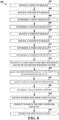
- FIG. 8 is a flowchart of a method of wireless communication 800 in accordance with some aspects of the present disclosure.
- a remote UE may receive a first PC5 message from a first potential relay UE.
- the remote UE 508, 608 may receive a first PC5 message from the first potential relay UE 504, 604.
- the remote UE may determine a first link quality based on the received first PC5 message.
- the remote UE may receive a second PC5 message from the first potential relay UE.
- the remote UE 508, 608 may receive a second PC5 message from the first potential relay UE 504, 604.
- the second PC5 message may include information indicating a second link quality.
- the remote UE may determine the second link quality based on the received second PC5 message.
- the remote UE determines a first link quality.
- the first link quality indicates a link quality of a first link between a first potential relay UE and the remote UE.
- the first link quality may be determined based on the received first PC5 message.
- the remote UE 508, 608 may determine the first link quality.
- the first link quality indicates the link quality of the first link between the first potential relay UE 504, 604 and the remote UE 508, 608.
- the remote UE 508, 608 may determine the first link quality based on the received first PC5 message. Specifically, the remote UE 508, 608 may determine the first link quality by determining at least one of RSRP, RSRQ, SNR, SINR or some other calculable value of the received first PC5 message indicative of link quality of the first link.
- the remote UE determines a second link quality.
- the second link quality indicates a link quality of a second link between the first potential relay UE and a first base station.
- the second PC5 message may include information indicating the second link quality.
- the remote UE 508, 608 may determine a second link quality.
- the second link quality indicates a link quality of a second link between the first potential relay UE 504, 604 and a first base station 502, 602A.
- the second PC5 message may include information indicating the second link quality.
- the information may be at least one of an RSRP, an RSRQ, an SNR, or an SINR of the second link.
- the remote UE may receive a third PC5 message from the second potential relay UE.
- the remote UE 508, 608 may receive a third PC5 message from the second potential relay UE 506, 606.
- the remote UE may determine a third link quality based on the received third PC5 message.
- the remote UE may receive a fourth PC5 message from the second potential relay LTE.
- the remote LTE 508, 608 may receive a fourth PC5 message from the second potential relay UE 506, 606.
- the fourth PC5 message may include information indicating a fourth link quality.
- the remote LTE may determine the fourth link quality based on the received fourth PC5 message.
- the remote UE determines a third link quality.
- the third link quality indicates a link quality of a third link between the second potential relay UE and the remote UE.
- the third link quality may be determined based on the received third PC5 message.
- the remote UE 508, 608 may determine a third link quality.
- the third link quality indicates a link quality of a third link between the second potential relay UE 506, 606 and the remote UE 508, 608.
- the third link quality may be determined based on the received third PC5 message.
- the remote UE 508, 608 may determine the third link quality by determining at least one of RSRP, RSRQ, SNR, SINR or some other calculable value of the received third PC5 message indicative of link quality of the third link.
- the remote UE determines a fourth link quality.
- the fourth link quality indicates a link quality of a fourth link between the second potential relay LTE and a second base station.
- the fourth PC5 message may include information indicating the fourth link quality.
- the remote UE 608 may determine a fourth link quality.
- the fourth link quality indicates a link quality of a fourth link between the second potential relay UE 606 and a second base station 602B.
- the fourth PC5 message may include information indicating the fourth link quality.
- the information may be at least one of an RSRP, an RSRQ, an SNR, or an SINR of the fourth link.
- the remote UE may receive information indicating at least one of the first weighting factor or the second weighting factor from a serving base station.
- the remote UE 508, 608 may receive information indicating at least one of the first weighting factor w1 or the second weighting factor w2 from a base station 502, 602A, 602B.
- the remote UE 508, 608 may receive information indicating at least one of the first weighting factor w1 or the second weighting factor w2 from one of the first potential relay UE 504, 604 or the second potential relay UE 506, 606 as a part of a PC5 message. In some examples, the remote UE 508, 608 may receive information indicating at least one of the first weighting factor w1 or the second weighting factor w2 from a first base station 502 (which may be a serving base station) over Uu_1, through the first potential relay UE 504, 604, and over a PC5 link, PC5_1, as illustrated in FIGS. 5 , 6 .
- a first base station 502 which may be a serving base station
- the remote UE 508, 608 may receive information indicating at least one of the first weighting factor w1 or the second weighting factor w2 from a first base station 502, 602A over Uu_1, when the remote UE 508, 608 is in coverage of the first base station 502, 602A.
- the remote UE ranks the first potential relay UE relative to a second potential relay UE.
- the ranking of the first potential relay UE is based on a combination of the first link quality and the second link quality.
- the remote UE 508, 608 ranks the first potential relay UE 504, 604 relative to a second potential relay UE 506, 606.
- the ranking of the first potential relay UE 504, 604 is based on a combination of the first link quality and the second link quality.
- ranking of the first potential relay UE 504, 604 includes combining the first link quality and the second link quality and using the combined first link quality and second link quality to compare the first potential relay UE 504, 604 against other UEs, e.g., the second potential relay UEs 506, 606.
- the remote UE 508 combines the first link quality and the second link quality.
- the remote UE 508, 608 uses the combined first link quality and second link quality to compare the first potential relay UE 504, 604 against other UEs, e.g., the potential relay UEs 506, 606.
- Ranking the first potential relay UE 504, 604 relative to a second potential relay UE 506, 606, includes comparing the combination of the first link quality and the second link quality to a combination of the third link quality and the fourth link quality. Accordingly, the remote UE 508 compares the combination of the first link quality and the second link quality to a combination of the third link quality and the fourth link quality.
- the remote UE selects one of a first potential relay UE and a second potential relay UE for a relay connection based on the ranking of the first potential relay UE relative to the second potential relay UE.
- the remote UE 508, 608 selects one of the first potential relay UE 504, 604 and the second potential relay UE 506, 606 for a relay connection based on the ranking of the first potential relay LTE 504, 604 relative to the second potential relay UE 506, 606.
- Selecting a potential relay UE 504, 506, 604, 606 based on the ranking of the first potential relay UE 504, 604 and the second potential relay UE 506, 606 includes comparing the rankings of the first potential relay UE 504, 604 and the second potential relay UE 506, 606 and choosing the potential relay with the highest ranking. Accordingly, the remote UE 508, 608 compares the rankings of the first potential relay UE 504, 604 and the second potential relay UE 506, 606 and chooses the potential relay UE 504, 506 604, 606 with the highest ranking.
- the remote LTE may transmit a measurement report to the first base station.
- the measurement report may include at least one of the first link quality and the second link quality.
- the remote UE 508, 608 may transmit a measurement report to the first base station 502, 602.
- the measurement report may include at least one of the first link quality and the second link quality.
- the measurement report may further include at least one of the third link quality and the fourth link quality.
- the remote UE may receive information from the first based station indicating at least one of the first potential relay UE or the second potential relay UE.
- the received information may be based on the transmitted measurement report.
- the remote UE 508, 608 may receive information from the first base station 502, 602A indicating at least one of the first potential relay UE 504, 604 or the second potential relay UE 506, 606.
- the received information may be based on the transmitted measurement report.
- the remote UE may connect to one of a first potential relay UE or a second potential relay UE based on the received information.
- the remote UE 508, 608 may connect to one of the first potential relay UE 504, 604 or the second potential relay UE 506, 606 based on the received information.
- the remote UE may inform the first base station when at least one of the remote UE is successful at connecting to the one of a first potential relay UE or a second potential relay UE, or a remote UE has failed to connect to the relay UE.
- the remote UE 508, 608 may inform the first base station 502, 602A when at least one of the remote UE 508, 608 is successful at connecting to the one of the first potential relay UE 504, 604 or the second potential relay UE 506, 606, or the remote UE 508, 608 has failed to connect to the relay UE.
- a remote UE 508 may transition from an RRC connected state to an RRC idle state with respect to a first base station 502 upon successfully connecting to one of the first potential relay UE 504 or the second potential relay UE 506.
- a remote UE 508 may be in an RRC connected state with the first base station 502 when in range of the first base station 502 (i.e., when remote UE 508 is not actually "remote") and may use a relay, e.g., first potential relay UE 504 when not in range of the first base station 502.
- the remote UE 508 may be in RRC idle state with respect to a first base station 502 upon successfully connecting to one of the first potential relay UE 504 or the second potential relay UE 506.
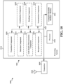
- FIG. 9 is a conceptual data flow diagram 900 illustrating the data flow between different means/components in an exemplary apparatus 902.
- the apparatus may be a UE.
- the apparatus may include a reception component 904 (e.g., RX1 930) that receives a first PC5 message from the first potential relay UE.
- the first link quality may be determined based on the received first PC5 message.
- the reception component 904 e.g., RX2 932
- the second PC5 message may include information indicating the second link quality.
- the reception component 904 (e.g., RX3 934) may receive a third PC5 message from the second potential relay UE.
- the third link quality may be determined based on the received third PC5 message.
- the reception component 904 e.g., RX4 936) may receive a fourth PC5 message from the second potential relay UE.
- the fourth PC5 message may include information indicating the fourth link quality.
- the apparatus 902 includes a first determination component 906 that determes a first link quality.
- the first link quality indicates a link quality of a first link between a first potential relay UE and the remote UE.
- the apparatus includes a second determination component 908 that determes a second link quality.
- the second link quality indicates a link quality of a second link between the first potential relay UE and a first base station.
- the apparatus includes a third determination component 910 that determines a third link quality.
- the third link quality indicates a link quality of a third link between the second potential relay UE and the remote UE.
- the apparatus includes a fourth determination component 912 that determines a fourth link quality.
- the fourth link quality indicates a link quality of a fourth link between the second potential relay UE and a second base station.
- the first link quality of the first link may be determined by determining at least one of an RSRP, an RSRQ, an SNR, or an SINR of the first PC5 message.
- the second link quality may also be a function of at least one of a an RSRP, an RSRQ, an SNR, or an SINR of the second link.
- the first PC5 message and the second PC5 message may be the same PC5 message.
- the first base station and the second base station are a single base station.
- the first determination component 906 may receive signals 940 from the reception component 904, e.g., RX1 930. The signals may be measured to determine RSRP, RSRQ, SNR, or SINR, for example.
- the signals may include information related to the determination of the signal quality, e.g., RSRP, RSRQ, SNR, or SINR.
- the first-fourth determination components may measure the signals 940, 942, 944, 946 to determine RSRP, RSRQ, SNR, or SINR, for example.
- the second determination component 908 may receive signals 942 from the reception component 904, e.g., RX1 932
- the third determination component 910 may receive signals 944 from the reception component 904, e.g., RX1 934
- the fourth determination component 912 may receive signals 946 from the reception component 904, e.g., RX1 936.
- the signals may be measured to determine RSRP, RSRQ, SNR, or SINR, for example.
- the signals may include information related to the determination of the signal quality, e.g., RSRP, RSRQ, SNR, or SINR.
- the first-fourth determination components may measure the signals 940, 942, 944, 946 to determine RSRP, RSRQ, SNR, or SINR, for example.
- the apparatus 902 includes a combination component 914 that combines the first link quality and the second link quality by applying a first weighting factor to the first link quality and applying a second weighting factor to the second link quality. Multiple link quality determinations (e.g., first-fourth) may be combined. The quality determinations may be communicated to the combination component using signals 950, 952, 954, 956.
- the apparatus 902 includes a ranking component 916 that ranks the first potential relay UE relative to a second potential relay UE.
- the ranking of the first potential relay UE is based on a combination of the first link quality and the second link quality.
- the ranking component 916 ranks the first potential relay UE relative to the second potential relay UE further based on a combination of the third link quality and the fourth link quality.
- the ranking further includes selecting a minimum of the first link quality and the second link quality.
- the ranking is based on a linear average of the first link quality and the second link quality.
- the ranking includes combining the first link quality and the second link quality by applying a first weighting factor to the first link quality and applying a second weighting factor to the second link quality.
- the combination component 914 may be part of the ranking component 916. In some examples, the combination component may be a separate component as illustrated in FIG. 9 . The combination component 914 may communicate with the ranking component using signal(s) 958.
- the first weighting factor and the second weighting factor may be fixed values. In one example, the first weighting factor and the second weighting factor may be preconfigured in the remote UE. In one example, the remote UE may receive information indicating at least one of the first weighting factor or the second weighting factor from a first base station. In one example, the information indicating the at least one of the first weighting factor or the second weighting factor may be received in a SIB from the first base station 922. In another example, the information indicating the at least one of the first weighting factor or the second weighting factor is received as a dedicated RRC signaling from the first base station 922. In another example, the remote UE receives information indicating at least one of the first weighting factor or the second weighting factor from one of the first potential relay UE or the second potential relay UE as a part of a PC5 message.
- the apparatus 902 includes a selection component 918 that selects one of the first potential relay UE and the second potential relay UE for a relay connection based on the ranking of the first potential relay UE relative to the second potential relay UE.
- the selection component selects one of the first potential relay UE and the second potential relay UE based on a highest ranking of the first potential relay UE and the second potential relay UE. Rankings may be communicated to the selection component 918 using signal(s) 960.
- the apparatus 902 may include a transmission component 920 that transmits a measurement report to the first base station.
- the measurement report may include at least one of the first link quality and the second link quality.
- the reception component 904 may receive information from the first based station indicating at least one of the first potential relay UE or the second potential relay UE. The received information may be based on the transmitted measurement report.
- the remote UE may connect to one of the first potential relay UE or the second potential relay UE based on the received information.
- the transmission component may inform the first base station 922 when at least one of the remote UE is successful at connecting to the one of the first potential relay UE or the second potential relay UE, or the remote UE has failed to connect to the relay UE.
- the apparatus 902 may transitioning from an RRC connected state to an RRC idle state with respect to a first base station 922 upon successfully connecting to one of the first potential relay UE 964 or the second potential relay UE (not shown).
- the transmission component may communicate with the selection component over signal(s) 962.
- the first base station 922 may communicate with the apparatus 902 through a first potential relay UE 964.
- the base station may communicate with the first potential relay UE 964 over communication channel 928 and the relay UE may communicate with the apparatus 902 over transmission signal 924 and receive signal 926.
- the apparatus 902 may include additional components that perform each of the blocks of the algorithm in the aforementioned flowcharts of FIG. 8 . As such, each block in the aforementioned flowcharts of FIG. 8 may be performed by a component and the apparatus may include one or more of those components.
- the components may be one or more hardware components specifically configured to carry out the stated processes/algorithm, implemented by a processor configured to perform the stated processes/algorithm, stored within a computer-readable medium for implementation by a processor, or some combination thereof.
- FIG. 10 is a diagram 1000 illustrating an example of a hardware implementation for an apparatus 902' employing a processing system 1014.
- the processing system 1014 may be implemented with a bus architecture, represented generally by the bus 1024.
- the bus 1024 may include any number of interconnecting buses and bridges depending on the specific application of the processing system 1014 and the overall design constraints.
- the bus 1024 links together various circuits including one or more processors and/or hardware components, represented by the processor 1004, the components 904, 906, 908, 910, 912, 914, 916, 918, 920 and the computer-readable medium / memory 1006.
- the bus 1024 may also link various other circuits such as timing sources, peripherals, voltage regulators, and power management circuits, which are well known in the art, and therefore, will not be described any further.
- the processing system 1014 may be coupled to a transceiver 1010.
- the transceiver 1010 is coupled to one or more antennas 1020.
- the transceiver 1010 provides a means for communicating with various other apparatus over a transmission medium.
- the transceiver 1010 receives a signal from the one or more antennas 1020, extracts information from the received signal, and provides the extracted information to the processing system 1014, specifically the reception component 1008.
- the transceiver 1010 receives information from the processing system 1014, specifically the transmission component 1012, and based on the received information, generates a signal to be applied to the one or more antennas 1020.
- the processing system 1014 includes a processor 1004 coupled to a computer-readable medium / memory 1006.
- the processor 1004 is responsible for general processing, including the execution of software stored on the computer-readable medium / memory 1006.
- the software when executed by the processor 1004, causes the processing system 1014 to perform the various functions described supra for any particular apparatus.
- the computer-readable medium / memory 1006 may also be used for storing data that is manipulated by the processor 1004 when executing software.
- the processing system 1014 further includes at least one of the components 904, 906, 908,910, 912, 914, 916, 918, 920 .
- the components may be software components running in the processor 1004, resident/stored in the computer readable medium / memory 1006, one or more hardware components coupled to the processor 1004, or some combination thereof.
- the processing system 1014 may be a component of the UE 350 and may include the memory 360 and/or at least one of the TX processor 368, the RX processor 356, and the controller/processor 359.
- a remote UE for wireless communication includes means for determining a first link quality.
- the first link quality indicates a link quality of a first link between a first potential relay UE and the remote UE.
- the remote UE further includes means for determining a second link quality.
- the second link quality indicates a link quality of a second link between the first potential relay UE and a first base station.
- the remote UE further includes means for ranking the first potential relay UE relative to a second potential relay UE. The ranking of the first potential relay UE is based on a combination of the first link quality and the second link quality.
- the remote UE further includes means for selecting one of the first potential relay UE and the second potential relay UE for a relay connection based on the ranking of the first potential relay UE relative to the second potential relay UE.
- the remote UE may further include means for receiving a first PC5 message from the first potential relay UE.
- the first link quality is determined based on the received first PC5 message.
- the remote UE may further include means for receiving a second PC5 message from the first potential relay UE.
- the second PC5 message includes information indicating the second link quality.
- the first PC5 message and the second PC5 message are the same PC5 message.
- the first link quality of the first link is determined by determining at least one of an RSRP, an RSRQ, an SNR, or an SINR of the first PC5 message.
- the second link quality is a function of at least one of an RSRP, an RSRQ, an SNR, or an SINR of the second link.
- the remote UE further includes means for determining a third link quality.
- the third link quality indicates a link quality of a third link between the second potential relay UE and the remote UE.
- the remote UE further includes means for determining a fourth link quality.
- the fourth link quality indicates a link quality of a fourth link between the second potential relay UE and a second base station.
- the first potential relay UE is ranked relative to the second potential relay UE further based on a combination of the third link quality and the fourth link quality.
- the remote UE may further include means for receiving a third PC5 message from the second potential relay UE.
- the third link quality may be determined based on the received third PC5 message.
- the remote UE may further include means for receiving a fourth PC5 message from the second potential relay UE.
- the fourth PC5 message may include information indicating the fourth link quality.
- the first base station and the second base station are a single base station.
- One of the first potential relay UE and the second potential relay UE is selected based on a highest ranking of the first potential relay UE and the second potential relay UE.
- the ranking includes combining the first link quality and the second link quality by applying a first weighting factor to the first link quality and applying a second weighting factor to the second link quality.
- the first weighting factor and the second weighting factor are fixed values.
- the first weighting factor and the second weighting factor are preconfigured in the remote UE.
- the remote UE may further include means for receiving information indicating at least one of the first weighting factor or the second weighting factor from a serving base station.
- the information may indicate the at least one of the first weighting factor or the second weighting factor is received in a SIB from the serving base station.
- the information indicating the at least one of the first weighting factor or the second weighting factor is received as a dedicated RRC signaling from the serving base station.
- the remote UE may further include means for receiving information indicating at least one of the first weighting factor or the second weighting factor from one of the first potential relay UE or the second potential relay UE as a part of a PC5 message.
- ranking further includes selecting a minimum of the first link quality and the second link quality. In one configuration not covered by the claims, the ranking is based on a linear average of the first link quality and the second link quality.
- the relay UE further includes means for transmitting a measurement report to the first base station. The measurement report including at least one of the first link quality and the second link quality.
- the relay UE may further include means for receiving information from the first based station indicating at least one of the first potential relay UE or the second potential relay UE. The received information being based on the transmitted measurement report.
- the relay UE may further include means for connecting to one of the first potential relay UE or the second potential relay UE based on the received information.
- the relay UE may further include means for informing the first base station when at least one of the remote UE is successful at connecting to the one of the first potential relay UE or the second potential relay UE, or the remote UE has failed to connect to the relay UE.
- the relay UE may further include means for transitioning from an RRC connected state to an RRC idle state with respect to a serving base station upon successfully connecting to one of the first potential relay UE or the second potential relay UE.
- the aforementioned means may be one or more of the aforementioned components of the apparatus 902 and/or the processing system 1014 of the apparatus 902' configured to perform the functions recited by the aforementioned means.
- the processing system 1014 may include the TX Processor 368, the RX Processor 356, and the controller/processor 359.
- the aforementioned means may be the TX Processor 368, the RX Processor 356, and the controller/processor 359 configured to perform the functions recited by the aforementioned means.
- Combinations such as "at least one of A, B, or C,” “one or more of A, B, or C,” “at least one of A, B, and C,” “one or more of A, B, and C,” and "A, B, C, or any combination thereof' include any combination of A, B, and/or C, and may include multiples of A, multiples of B, or multiples of C.
- combinations such as “at least one of A, B, or C,” “one or more of A, B, or C,” “at least one of A, B, and C,” “one or more of A, B, and C,” and “A, B, C, or any combination thereof' may be A only, B only, C only, A and B, A and C, B and C, or A and B and C, where any such combinations may contain one or more member or members of A, B, or C.
Landscapes
- Engineering & Computer Science (AREA)
- Computer Networks & Wireless Communication (AREA)
- Signal Processing (AREA)
- Computer Security & Cryptography (AREA)
- Mobile Radio Communication Systems (AREA)
Applications Claiming Priority (3)
| Application Number | Priority Date | Filing Date | Title |
|---|---|---|---|
| US201562161874P | 2015-05-14 | 2015-05-14 | |
| US15/086,814 US10212651B2 (en) | 2015-05-14 | 2016-03-31 | Systems, methods, and devices for link quality based relay selection |
| PCT/US2016/025686 WO2016182642A1 (en) | 2015-05-14 | 2016-04-01 | Systems, methods, and devices for link quality based relay selection |
Publications (2)
| Publication Number | Publication Date |
|---|---|
| EP3295759A1 EP3295759A1 (en) | 2018-03-21 |
| EP3295759B1 true EP3295759B1 (en) | 2023-08-30 |
Family
ID=55806774
Family Applications (1)
| Application Number | Title | Priority Date | Filing Date |
|---|---|---|---|
| EP16718069.4A Active EP3295759B1 (en) | 2015-05-14 | 2016-04-01 | Method for link quality based relay selection, apparatus and computer-readable medium |
Country Status (6)
| Country | Link |
|---|---|
| US (1) | US10212651B2 (zh) |
| EP (1) | EP3295759B1 (zh) |
| JP (1) | JP6703008B2 (zh) |
| KR (1) | KR102487992B1 (zh) |
| CN (1) | CN108541389B (zh) |
| WO (1) | WO2016182642A1 (zh) |
Families Citing this family (56)
| Publication number | Priority date | Publication date | Assignee | Title |
|---|---|---|---|---|
| EP3286960B1 (en) * | 2015-05-22 | 2019-09-18 | Sony Corporation | Communications terminals, infrastructure equipment and methods, for user equipments acting as relays |
| US10136372B2 (en) * | 2015-09-22 | 2018-11-20 | Lg Electronics Inc. | Relay UE selecting method performed by UE in wireless communication system and UE using the same |
| WO2017050458A1 (en) * | 2015-09-23 | 2017-03-30 | Sony Corporation | Terminal device, method and system |
| US10609744B2 (en) * | 2015-10-22 | 2020-03-31 | Lg Electronics Inc. | Method for direct communication between terminals in wireless communication system and apparatus for method |
| WO2017079883A1 (zh) * | 2015-11-09 | 2017-05-18 | 华为技术有限公司 | 一种信号强度测量方法及设备 |
| EP3404957B1 (en) * | 2016-01-14 | 2020-11-11 | LG Electronics Inc. -1- | Method for measuring and reporting d2d resource in wireless communication system, and apparatus therefor |
| US20190037430A1 (en) * | 2016-03-17 | 2019-01-31 | Lg Electronics Inc. | Method and device for reporting sidelink resource occupancy level in wireless communication system |
| CN105897478B (zh) * | 2016-04-12 | 2019-02-05 | 腾讯科技(深圳)有限公司 | 一种链路决策的方法及决策设备 |
| KR102493536B1 (ko) * | 2016-06-08 | 2023-01-31 | 삼성전자주식회사 | 통신 단말의 릴레이 통신 방법 및 그 통신 단말 |
| US10517021B2 (en) | 2016-06-30 | 2019-12-24 | Evolve Cellular Inc. | Long term evolution-primary WiFi (LTE-PW) |
| JP6809027B2 (ja) * | 2016-08-08 | 2021-01-06 | ソニー株式会社 | 通信装置及び通信方法 |
| US10411980B2 (en) * | 2016-09-20 | 2019-09-10 | Intel Corporation | Proactive path quality reporting in packet transmission |
| WO2018072157A1 (zh) * | 2016-10-19 | 2018-04-26 | 华为技术有限公司 | 一种控制设备到设备间发现的方法及相关设备 |
| US11122493B2 (en) * | 2016-12-08 | 2021-09-14 | Nec Corporation | Apparatus and method for relay selection |
| US10893512B2 (en) * | 2017-01-16 | 2021-01-12 | Mediatek Inc. | Resource element (RE) allocation for uplink control information (UCI) on physical uplink shared channel (PUSCH) |
| CN109716857B (zh) * | 2017-01-26 | 2021-09-21 | 华为技术有限公司 | 一种中继确定方法及装置 |
| CN110249670B (zh) * | 2017-02-06 | 2022-04-26 | Lg 电子株式会社 | 在无线通信系统中执行具有与第一ue的连接的第二ue的寻呼有关的操作的方法及其装置 |
| WO2018174477A1 (en) * | 2017-03-22 | 2018-09-27 | Lg Electronics Inc. | Method for transmitting a mac ce in different tti durations in wireless communication system and a device therefor |
| CN108632919A (zh) * | 2017-03-23 | 2018-10-09 | 索尼公司 | 用于无线通信的电子装置以及无线通信方法 |
| WO2018194390A1 (en) * | 2017-04-20 | 2018-10-25 | Lg Electronics Inc. | Method for forwarding system information for a remote ue by a relay ue in wireless communication system and a device therefor |
| US10511507B2 (en) * | 2017-05-09 | 2019-12-17 | Cisco Technology, Inc. | Routing network traffic based on whether an application associated with traffic is a rerouting application as defined by a policy and whether a second path ranking exceeds a first path ranking |
| WO2018226034A1 (ko) * | 2017-06-06 | 2018-12-13 | 엘지전자 주식회사 | 무선 통신 시스템에서 eNB가 Remote UE로 하향링크 데이터를 전송하는 방법 및 이를 위한 장치 |
| US10951528B2 (en) * | 2017-07-31 | 2021-03-16 | Cisco Technology, Inc. | Network load balancing |
| EP3487088B1 (en) * | 2017-11-16 | 2023-03-01 | Juniper Networks, Inc. | Establishing communication with multiple networks to enable continuous communication coverage across the multiple networks |
| EP3739909B1 (en) * | 2018-01-09 | 2022-02-09 | Guangdong Oppo Mobile Telecommunications Corp., Ltd. | Method and apparatus for network self-organization |
| US11277784B2 (en) * | 2018-01-11 | 2022-03-15 | Sony Corporation | Wireless communications device and method |
| CN110611940A (zh) * | 2018-06-15 | 2019-12-24 | 海信集团有限公司 | 一种选择Relay UE的方法和设备 |
| CN110611944A (zh) * | 2018-06-15 | 2019-12-24 | 海信集团有限公司 | 一种重选Relay UE的方法和设备 |
| CN110611943A (zh) * | 2018-06-15 | 2019-12-24 | 海信集团有限公司 | 一种重选Relay UE的方法和设备 |
| CN113692727A (zh) * | 2019-04-17 | 2021-11-23 | 株式会社Ntt都科摩 | 终端以及由终端执行的方法 |
| JP7194647B2 (ja) | 2019-06-05 | 2022-12-22 | 本田技研工業株式会社 | 制御装置、プログラム、及び制御方法 |
| CN110446216A (zh) * | 2019-06-28 | 2019-11-12 | 维沃移动通信有限公司 | 一种数据传输方法及终端设备 |
| US20220369215A1 (en) | 2019-07-03 | 2022-11-17 | Koninklijke Philips N.V. | Relay selection in cellular sliced networks |
| EP3761751A1 (en) | 2019-07-03 | 2021-01-06 | Koninklijke Philips N.V. | Relay selection in cellular sliced networks |
| EP3849103A1 (en) | 2020-01-10 | 2021-07-14 | Koninklijke Philips N.V. | Relay selection in cellular sliced networks |
| CN110461020A (zh) * | 2019-08-16 | 2019-11-15 | 展讯通信(上海)有限公司 | 用于辅链路的中继选择方法及装置、存储介质、终端 |
| WO2021045596A1 (ko) * | 2019-09-06 | 2021-03-11 | 엘지전자 주식회사 | 무선통신시스템에서 사이드링크 자원의 해제에 관련된 기지국의 동작 방법 및 장치 |
| EP3809606A1 (en) * | 2019-10-15 | 2021-04-21 | Mitsubishi Electric R & D Centre Europe B.V. | Method for performing transmission between a base station and a terminal via a multi-hop network |
| CN113133080B (zh) * | 2020-01-15 | 2023-04-25 | 大唐移动通信设备有限公司 | 一种中继设备的选择方法、设备及计算机存储介质 |
| US20230088696A1 (en) * | 2020-02-28 | 2023-03-23 | Lg Electronics Inc. | Method for operating link quality-related relay ue in wireless communication system |
| CN113630821B (zh) * | 2020-05-09 | 2023-03-10 | 华为技术有限公司 | 通信方法及装置 |
| CN113676963B (zh) * | 2020-05-14 | 2023-03-14 | 展讯通信(上海)有限公司 | 切换方法及装置、存储介质、终端 |
| US20210410215A1 (en) * | 2020-06-29 | 2021-12-30 | Asustek Computer Inc. | Method and apparatus for sidelink data radio bearer establishment in a wireless communication system |
| WO2022027233A1 (en) | 2020-08-04 | 2022-02-10 | Zte Corporation | Systems and methods for relay services |
| EP4030800A1 (en) | 2021-01-19 | 2022-07-20 | Koninklijke Philips N.V. | Privacy of relay selection in cellular sliced networks |
| CN115968557A (zh) | 2020-08-21 | 2023-04-14 | 皇家飞利浦有限公司 | 蜂窝切片网络中的中继选择的隐私性 |
| WO2022067715A1 (en) * | 2020-09-30 | 2022-04-07 | Qualcomm Incorporated | Relay selection and re-selection assisted by discovery information |
| WO2022071571A1 (ja) * | 2020-10-01 | 2022-04-07 | 京セラ株式会社 | 通信制御方法、中継ユーザ装置、及び遠隔ユーザ装置 |
| WO2022086849A1 (en) * | 2020-10-22 | 2022-04-28 | Kyocera Corporation | Relay selection and reselection based on discovery message transmission resources |
| WO2022151000A1 (en) * | 2021-01-13 | 2022-07-21 | Qualcomm Incorporated | Hybrid measurement for sidelink relay selection |
| BR112023016285A2 (pt) * | 2021-02-25 | 2023-11-07 | Qualcomm Inc | Seleção de retransmissão para comunicações de multi-retransmissão |
| US20220361091A1 (en) * | 2021-05-07 | 2022-11-10 | Samsung Electronics Co., Ltd. | Method and apparatus for supporting system information acquisition by sidelink remote terminal over sidelink relay |
| EP4340454A1 (en) * | 2021-05-10 | 2024-03-20 | LG Electronics Inc. | Sib-related operation method and device of sidelink remote ue and relay ue in wireless communication system |
| US11606737B1 (en) * | 2021-10-15 | 2023-03-14 | Peltbeam Inc. | Communication system and method for a 5G mesh network for enhanced coverage |
| US11664917B1 (en) * | 2021-11-12 | 2023-05-30 | Qualcomm Incorporated | Techniques for inter-base station messaging for inter-base station cross-link interference mitigation |
| WO2023161431A1 (en) * | 2022-02-25 | 2023-08-31 | Telefonaktiebolaget Lm Ericsson (Publ) | Signaling and mechanisms for ue- or network-triggered mobility in multi-hop user-to-network (u2n) sidelink scenarios |
Family Cites Families (11)
| Publication number | Priority date | Publication date | Assignee | Title |
|---|---|---|---|---|
| US7873338B2 (en) * | 2006-11-06 | 2011-01-18 | Motorola Mobility, Inc. | Method and apparatus for determining an appropriate link path in a multi-hop communication system |
| JP4888431B2 (ja) * | 2007-03-26 | 2012-02-29 | 株式会社富士通ゼネラル | 無線通信システム及び無線通信システムにおける中継方法 |
| US8270374B2 (en) * | 2009-10-02 | 2012-09-18 | Research In Motion Limited | Determining link quality for networks having relays |
| JP5733567B2 (ja) * | 2011-03-29 | 2015-06-10 | ソニー株式会社 | 管理装置、管理方法、通信装置、通信方法、中継装置、中継方法、プログラム、及び通信システム |
| EP2810506B1 (en) * | 2012-01-16 | 2017-12-06 | Telefonaktiebolaget LM Ericsson (publ) | Method and arrangement for relaying |
| US8976662B2 (en) * | 2012-02-09 | 2015-03-10 | Qualcomm Incorporated | Apparatus and method for opportunistic relay association |
| CN103327550A (zh) * | 2012-03-20 | 2013-09-25 | 中国移动通信集团公司 | 一种中继系统中小区选择方法、终端、中继节点和系统 |
| GB2507514A (en) * | 2012-10-31 | 2014-05-07 | Nec Corp | Providing measurement reports for relay cells |
| US20140171062A1 (en) * | 2012-12-19 | 2014-06-19 | Telefonaktiebolaget L M Ericsson (Publ) | Wireless Devices, Network Node and Methods for Handling Relay Assistance in a Wireless Communications Network |
| US20160037568A1 (en) * | 2013-03-29 | 2016-02-04 | Sami-Jukka Hakola | Method and apparatus for reestablishing communication with a network |
| CN103796317B (zh) * | 2013-12-06 | 2017-01-11 | 南京邮电大学 | 一种基于终端直通中继通信的资源分配方法 |
-
2016
- 2016-03-31 US US15/086,814 patent/US10212651B2/en active Active
- 2016-04-01 EP EP16718069.4A patent/EP3295759B1/en active Active
- 2016-04-01 WO PCT/US2016/025686 patent/WO2016182642A1/en active Application Filing
- 2016-04-01 KR KR1020177032302A patent/KR102487992B1/ko active IP Right Grant
- 2016-04-01 CN CN201680027224.9A patent/CN108541389B/zh active Active
- 2016-04-01 JP JP2017558967A patent/JP6703008B2/ja active Active
Also Published As
| Publication number | Publication date |
|---|---|
| WO2016182642A1 (en) | 2016-11-17 |
| KR102487992B1 (ko) | 2023-01-11 |
| CN108541389A (zh) | 2018-09-14 |
| US20160337954A1 (en) | 2016-11-17 |
| JP2018519722A (ja) | 2018-07-19 |
| US10212651B2 (en) | 2019-02-19 |
| JP6703008B2 (ja) | 2020-06-03 |
| EP3295759A1 (en) | 2018-03-21 |
| CN108541389B (zh) | 2022-05-13 |
| KR20180008456A (ko) | 2018-01-24 |
Similar Documents
| Publication | Publication Date | Title |
|---|---|---|
| EP3295759B1 (en) | Method for link quality based relay selection, apparatus and computer-readable medium | |
| US10334586B2 (en) | Hybrid automatic repeat request feedback for unicast sidelink communications | |
| EP3278624B1 (en) | Systems, methods, and apparatus for managing a relay connection in a wireless communications network | |
| US10412571B2 (en) | Configuration by eNB for D2D UE to network relay search | |
| US11071155B2 (en) | Rate control of device-to-device based relay communication | |
| US9826460B2 (en) | Measurement of D2D channels | |
| EP3275274B1 (en) | Relay discovery and association messages | |
| EP3281426B1 (en) | Inter-frequency lte-d discovery | |
| US20170374704A1 (en) | Identification of a shared evolved packet core in a neutral host network | |
| EP3520474B1 (en) | Signaling to indicate whether physical broadcast channel repetition is enabled in a target cell | |
| WO2019213889A1 (en) | Uplink configuration change request |
Legal Events
| Date | Code | Title | Description |
|---|---|---|---|
| STAA | Information on the status of an ep patent application or granted ep patent |
Free format text: STATUS: THE INTERNATIONAL PUBLICATION HAS BEEN MADE |
|
| PUAI | Public reference made under article 153(3) epc to a published international application that has entered the european phase |
Free format text: ORIGINAL CODE: 0009012 |
|
| STAA | Information on the status of an ep patent application or granted ep patent |
Free format text: STATUS: REQUEST FOR EXAMINATION WAS MADE |
|
| 17P | Request for examination filed |
Effective date: 20171012 |
|
| AK | Designated contracting states |
Kind code of ref document: A1 Designated state(s): AL AT BE BG CH CY CZ DE DK EE ES FI FR GB GR HR HU IE IS IT LI LT LU LV MC MK MT NL NO PL PT RO RS SE SI SK SM TR |
|
| AX | Request for extension of the european patent |
Extension state: BA ME |
|
| DAV | Request for validation of the european patent (deleted) | ||
| DAX | Request for extension of the european patent (deleted) | ||
| STAA | Information on the status of an ep patent application or granted ep patent |
Free format text: STATUS: EXAMINATION IS IN PROGRESS |
|
| 17Q | First examination report despatched |
Effective date: 20181030 |
|
| RIC1 | Information provided on ipc code assigned before grant |
Ipc: H04W 8/00 20090101ALI20161123BHEP Ipc: H04W 48/08 20090101ALI20161123BHEP Ipc: H04W 88/04 20090101ALI20161123BHEP Ipc: H04W 76/02 20181130AFI20161123BHEP |
|
| RIC1 | Information provided on ipc code assigned before grant |
Ipc: H04W 48/08 20090101ALI20161123BHEP Ipc: H04W 8/00 20090101ALI20161123BHEP Ipc: H04W 76/02 20090101AFI20161123BHEP Ipc: H04W 88/04 20090101ALI20161123BHEP |
|
| STAA | Information on the status of an ep patent application or granted ep patent |
Free format text: STATUS: EXAMINATION IS IN PROGRESS |
|
| STAA | Information on the status of an ep patent application or granted ep patent |
Free format text: STATUS: EXAMINATION IS IN PROGRESS |
|
| REG | Reference to a national code |
Ref country code: DE Ref legal event code: R079 Ref document number: 602016082287 Country of ref document: DE Free format text: PREVIOUS MAIN CLASS: H04W0076020000 Ipc: H04W0076140000 Ref country code: DE Ref legal event code: R079 Free format text: PREVIOUS MAIN CLASS: H04W0076020000 Ipc: H04W0076140000 |
|
| GRAP | Despatch of communication of intention to grant a patent |
Free format text: ORIGINAL CODE: EPIDOSNIGR1 |
|
| STAA | Information on the status of an ep patent application or granted ep patent |
Free format text: STATUS: GRANT OF PATENT IS INTENDED |
|
| RIC1 | Information provided on ipc code assigned before grant |
Ipc: H04W 48/12 20090101ALN20230221BHEP Ipc: H04W 40/12 20090101ALN20230221BHEP Ipc: H04W 88/04 20090101ALN20230221BHEP Ipc: H04W 8/00 20090101ALN20230221BHEP Ipc: H04W 76/14 20180101AFI20230221BHEP |
|
| INTG | Intention to grant announced |
Effective date: 20230315 |
|
| GRAS | Grant fee paid |
Free format text: ORIGINAL CODE: EPIDOSNIGR3 |
|
| GRAA | (expected) grant |
Free format text: ORIGINAL CODE: 0009210 |
|
| STAA | Information on the status of an ep patent application or granted ep patent |
Free format text: STATUS: THE PATENT HAS BEEN GRANTED |
|
| AK | Designated contracting states |
Kind code of ref document: B1 Designated state(s): AL AT BE BG CH CY CZ DE DK EE ES FI FR GB GR HR HU IE IS IT LI LT LU LV MC MK MT NL NO PL PT RO RS SE SI SK SM TR |
|
| REG | Reference to a national code |
Ref country code: GB Ref legal event code: FG4D |
|
| REG | Reference to a national code |
Ref country code: CH Ref legal event code: EP |
|
| REG | Reference to a national code |
Ref country code: DE Ref legal event code: R096 Ref document number: 602016082287 Country of ref document: DE |
|
| REG | Reference to a national code |
Ref country code: IE Ref legal event code: FG4D |
|
| REG | Reference to a national code |
Ref country code: LT Ref legal event code: MG9D |
|
| REG | Reference to a national code |
Ref country code: NL Ref legal event code: MP Effective date: 20230830 |
|
| REG | Reference to a national code |
Ref country code: AT Ref legal event code: MK05 Ref document number: 1607123 Country of ref document: AT Kind code of ref document: T Effective date: 20230830 |
|
| PG25 | Lapsed in a contracting state [announced via postgrant information from national office to epo] |
Ref country code: GR Free format text: LAPSE BECAUSE OF FAILURE TO SUBMIT A TRANSLATION OF THE DESCRIPTION OR TO PAY THE FEE WITHIN THE PRESCRIBED TIME-LIMIT Effective date: 20231201 |
|
| PG25 | Lapsed in a contracting state [announced via postgrant information from national office to epo] |
Ref country code: IS Free format text: LAPSE BECAUSE OF FAILURE TO SUBMIT A TRANSLATION OF THE DESCRIPTION OR TO PAY THE FEE WITHIN THE PRESCRIBED TIME-LIMIT Effective date: 20231230 |
|
| PG25 | Lapsed in a contracting state [announced via postgrant information from national office to epo] |
Ref country code: SE Free format text: LAPSE BECAUSE OF FAILURE TO SUBMIT A TRANSLATION OF THE DESCRIPTION OR TO PAY THE FEE WITHIN THE PRESCRIBED TIME-LIMIT Effective date: 20230830 Ref country code: RS Free format text: LAPSE BECAUSE OF FAILURE TO SUBMIT A TRANSLATION OF THE DESCRIPTION OR TO PAY THE FEE WITHIN THE PRESCRIBED TIME-LIMIT Effective date: 20230830 Ref country code: NO Free format text: LAPSE BECAUSE OF FAILURE TO SUBMIT A TRANSLATION OF THE DESCRIPTION OR TO PAY THE FEE WITHIN THE PRESCRIBED TIME-LIMIT Effective date: 20231130 Ref country code: LV Free format text: LAPSE BECAUSE OF FAILURE TO SUBMIT A TRANSLATION OF THE DESCRIPTION OR TO PAY THE FEE WITHIN THE PRESCRIBED TIME-LIMIT Effective date: 20230830 Ref country code: LT Free format text: LAPSE BECAUSE OF FAILURE TO SUBMIT A TRANSLATION OF THE DESCRIPTION OR TO PAY THE FEE WITHIN THE PRESCRIBED TIME-LIMIT Effective date: 20230830 Ref country code: IS Free format text: LAPSE BECAUSE OF FAILURE TO SUBMIT A TRANSLATION OF THE DESCRIPTION OR TO PAY THE FEE WITHIN THE PRESCRIBED TIME-LIMIT Effective date: 20231230 Ref country code: HR Free format text: LAPSE BECAUSE OF FAILURE TO SUBMIT A TRANSLATION OF THE DESCRIPTION OR TO PAY THE FEE WITHIN THE PRESCRIBED TIME-LIMIT Effective date: 20230830 Ref country code: GR Free format text: LAPSE BECAUSE OF FAILURE TO SUBMIT A TRANSLATION OF THE DESCRIPTION OR TO PAY THE FEE WITHIN THE PRESCRIBED TIME-LIMIT Effective date: 20231201 Ref country code: FI Free format text: LAPSE BECAUSE OF FAILURE TO SUBMIT A TRANSLATION OF THE DESCRIPTION OR TO PAY THE FEE WITHIN THE PRESCRIBED TIME-LIMIT Effective date: 20230830 Ref country code: AT Free format text: LAPSE BECAUSE OF FAILURE TO SUBMIT A TRANSLATION OF THE DESCRIPTION OR TO PAY THE FEE WITHIN THE PRESCRIBED TIME-LIMIT Effective date: 20230830 |
|
| PG25 | Lapsed in a contracting state [announced via postgrant information from national office to epo] |
Ref country code: PL Free format text: LAPSE BECAUSE OF FAILURE TO SUBMIT A TRANSLATION OF THE DESCRIPTION OR TO PAY THE FEE WITHIN THE PRESCRIBED TIME-LIMIT Effective date: 20230830 Ref country code: NL Free format text: LAPSE BECAUSE OF FAILURE TO SUBMIT A TRANSLATION OF THE DESCRIPTION OR TO PAY THE FEE WITHIN THE PRESCRIBED TIME-LIMIT Effective date: 20230830 |
|
| PG25 | Lapsed in a contracting state [announced via postgrant information from national office to epo] |
Ref country code: ES Free format text: LAPSE BECAUSE OF FAILURE TO SUBMIT A TRANSLATION OF THE DESCRIPTION OR TO PAY THE FEE WITHIN THE PRESCRIBED TIME-LIMIT Effective date: 20230830 |
|
| PG25 | Lapsed in a contracting state [announced via postgrant information from national office to epo] |
Ref country code: SM Free format text: LAPSE BECAUSE OF FAILURE TO SUBMIT A TRANSLATION OF THE DESCRIPTION OR TO PAY THE FEE WITHIN THE PRESCRIBED TIME-LIMIT Effective date: 20230830 Ref country code: RO Free format text: LAPSE BECAUSE OF FAILURE TO SUBMIT A TRANSLATION OF THE DESCRIPTION OR TO PAY THE FEE WITHIN THE PRESCRIBED TIME-LIMIT Effective date: 20230830 Ref country code: ES Free format text: LAPSE BECAUSE OF FAILURE TO SUBMIT A TRANSLATION OF THE DESCRIPTION OR TO PAY THE FEE WITHIN THE PRESCRIBED TIME-LIMIT Effective date: 20230830 Ref country code: EE Free format text: LAPSE BECAUSE OF FAILURE TO SUBMIT A TRANSLATION OF THE DESCRIPTION OR TO PAY THE FEE WITHIN THE PRESCRIBED TIME-LIMIT Effective date: 20230830 Ref country code: DK Free format text: LAPSE BECAUSE OF FAILURE TO SUBMIT A TRANSLATION OF THE DESCRIPTION OR TO PAY THE FEE WITHIN THE PRESCRIBED TIME-LIMIT Effective date: 20230830 Ref country code: CZ Free format text: LAPSE BECAUSE OF FAILURE TO SUBMIT A TRANSLATION OF THE DESCRIPTION OR TO PAY THE FEE WITHIN THE PRESCRIBED TIME-LIMIT Effective date: 20230830 Ref country code: SK Free format text: LAPSE BECAUSE OF FAILURE TO SUBMIT A TRANSLATION OF THE DESCRIPTION OR TO PAY THE FEE WITHIN THE PRESCRIBED TIME-LIMIT Effective date: 20230830 Ref country code: PT Free format text: LAPSE BECAUSE OF FAILURE TO SUBMIT A TRANSLATION OF THE DESCRIPTION OR TO PAY THE FEE WITHIN THE PRESCRIBED TIME-LIMIT Effective date: 20240102 |
|
| PGFP | Annual fee paid to national office [announced via postgrant information from national office to epo] |
Ref country code: GB Payment date: 20240314 Year of fee payment: 9 |