EP3295267B1 - Bodenbearbeitungsgerät und verfahren zu dessen navigation sowie schwarm von bodenbearbeitungsgeräten und verfahren zu deren gemeinsamer navigation - Google Patents
Bodenbearbeitungsgerät und verfahren zu dessen navigation sowie schwarm von bodenbearbeitungsgeräten und verfahren zu deren gemeinsamer navigation Download PDFInfo
- Publication number
- EP3295267B1 EP3295267B1 EP16721634.0A EP16721634A EP3295267B1 EP 3295267 B1 EP3295267 B1 EP 3295267B1 EP 16721634 A EP16721634 A EP 16721634A EP 3295267 B1 EP3295267 B1 EP 3295267B1
- Authority
- EP
- European Patent Office
- Prior art keywords
- surroundings
- floor treatment
- images
- treatment device
- image
- Prior art date
- Legal status (The legal status is an assumption and is not a legal conclusion. Google has not performed a legal analysis and makes no representation as to the accuracy of the status listed.)
- Active
Links
Images

Classifications
-
- G—PHYSICS
- G05—CONTROLLING; REGULATING
- G05D—SYSTEMS FOR CONTROLLING OR REGULATING NON-ELECTRIC VARIABLES
- G05D1/00—Control of position, course, altitude or attitude of land, water, air or space vehicles, e.g. using automatic pilots
- G05D1/02—Control of position or course in two dimensions
- G05D1/021—Control of position or course in two dimensions specially adapted to land vehicles
- G05D1/0212—Control of position or course in two dimensions specially adapted to land vehicles with means for defining a desired trajectory
- G05D1/0219—Control of position or course in two dimensions specially adapted to land vehicles with means for defining a desired trajectory ensuring the processing of the whole working surface
-
- A—HUMAN NECESSITIES
- A47—FURNITURE; DOMESTIC ARTICLES OR APPLIANCES; COFFEE MILLS; SPICE MILLS; SUCTION CLEANERS IN GENERAL
- A47L—DOMESTIC WASHING OR CLEANING; SUCTION CLEANERS IN GENERAL
- A47L9/00—Details or accessories of suction cleaners, e.g. mechanical means for controlling the suction or for effecting pulsating action; Storing devices specially adapted to suction cleaners or parts thereof; Carrying-vehicles specially adapted for suction cleaners
- A47L9/28—Installation of the electric equipment, e.g. adaptation or attachment to the suction cleaner; Controlling suction cleaners by electric means
-
- G—PHYSICS
- G01—MEASURING; TESTING
- G01C—MEASURING DISTANCES, LEVELS OR BEARINGS; SURVEYING; NAVIGATION; GYROSCOPIC INSTRUMENTS; PHOTOGRAMMETRY OR VIDEOGRAMMETRY
- G01C21/00—Navigation; Navigational instruments not provided for in groups G01C1/00 - G01C19/00
- G01C21/20—Instruments for performing navigational calculations
- G01C21/206—Instruments for performing navigational calculations specially adapted for indoor navigation
-
- G—PHYSICS
- G05—CONTROLLING; REGULATING
- G05D—SYSTEMS FOR CONTROLLING OR REGULATING NON-ELECTRIC VARIABLES
- G05D1/00—Control of position, course, altitude or attitude of land, water, air or space vehicles, e.g. using automatic pilots
- G05D1/02—Control of position or course in two dimensions
- G05D1/021—Control of position or course in two dimensions specially adapted to land vehicles
- G05D1/0231—Control of position or course in two dimensions specially adapted to land vehicles using optical position detecting means
- G05D1/0238—Control of position or course in two dimensions specially adapted to land vehicles using optical position detecting means using obstacle or wall sensors
- G05D1/024—Control of position or course in two dimensions specially adapted to land vehicles using optical position detecting means using obstacle or wall sensors in combination with a laser
-
- G—PHYSICS
- G05—CONTROLLING; REGULATING
- G05D—SYSTEMS FOR CONTROLLING OR REGULATING NON-ELECTRIC VARIABLES
- G05D1/00—Control of position, course, altitude or attitude of land, water, air or space vehicles, e.g. using automatic pilots
- G05D1/02—Control of position or course in two dimensions
- G05D1/021—Control of position or course in two dimensions specially adapted to land vehicles
- G05D1/0231—Control of position or course in two dimensions specially adapted to land vehicles using optical position detecting means
- G05D1/0246—Control of position or course in two dimensions specially adapted to land vehicles using optical position detecting means using a video camera in combination with image processing means
- G05D1/0248—Control of position or course in two dimensions specially adapted to land vehicles using optical position detecting means using a video camera in combination with image processing means in combination with a laser
-
- G—PHYSICS
- G05—CONTROLLING; REGULATING
- G05D—SYSTEMS FOR CONTROLLING OR REGULATING NON-ELECTRIC VARIABLES
- G05D1/00—Control of position, course, altitude or attitude of land, water, air or space vehicles, e.g. using automatic pilots
- G05D1/02—Control of position or course in two dimensions
- G05D1/021—Control of position or course in two dimensions specially adapted to land vehicles
- G05D1/0268—Control of position or course in two dimensions specially adapted to land vehicles using internal positioning means
- G05D1/0272—Control of position or course in two dimensions specially adapted to land vehicles using internal positioning means comprising means for registering the travel distance, e.g. revolutions of wheels
-
- G—PHYSICS
- G05—CONTROLLING; REGULATING
- G05D—SYSTEMS FOR CONTROLLING OR REGULATING NON-ELECTRIC VARIABLES
- G05D1/00—Control of position, course, altitude or attitude of land, water, air or space vehicles, e.g. using automatic pilots
- G05D1/02—Control of position or course in two dimensions
- G05D1/021—Control of position or course in two dimensions specially adapted to land vehicles
- G05D1/0268—Control of position or course in two dimensions specially adapted to land vehicles using internal positioning means
- G05D1/0274—Control of position or course in two dimensions specially adapted to land vehicles using internal positioning means using mapping information stored in a memory device
-
- G—PHYSICS
- G05—CONTROLLING; REGULATING
- G05D—SYSTEMS FOR CONTROLLING OR REGULATING NON-ELECTRIC VARIABLES
- G05D1/00—Control of position, course, altitude or attitude of land, water, air or space vehicles, e.g. using automatic pilots
- G05D1/02—Control of position or course in two dimensions
- G05D1/021—Control of position or course in two dimensions specially adapted to land vehicles
- G05D1/0287—Control of position or course in two dimensions specially adapted to land vehicles involving a plurality of land vehicles, e.g. fleet or convoy travelling
- G05D1/0291—Fleet control
- G05D1/0297—Fleet control by controlling means in a control room
-
- G—PHYSICS
- G06—COMPUTING OR CALCULATING; COUNTING
- G06F—ELECTRIC DIGITAL DATA PROCESSING
- G06F16/00—Information retrieval; Database structures therefor; File system structures therefor
- G06F16/20—Information retrieval; Database structures therefor; File system structures therefor of structured data, e.g. relational data
- G06F16/29—Geographical information databases
-
- G—PHYSICS
- G06—COMPUTING OR CALCULATING; COUNTING
- G06F—ELECTRIC DIGITAL DATA PROCESSING
- G06F16/00—Information retrieval; Database structures therefor; File system structures therefor
- G06F16/50—Information retrieval; Database structures therefor; File system structures therefor of still image data
- G06F16/58—Retrieval characterised by using metadata, e.g. metadata not derived from the content or metadata generated manually
- G06F16/5866—Retrieval characterised by using metadata, e.g. metadata not derived from the content or metadata generated manually using information manually generated, e.g. tags, keywords, comments, manually generated location and time information
-
- G—PHYSICS
- G06—COMPUTING OR CALCULATING; COUNTING
- G06V—IMAGE OR VIDEO RECOGNITION OR UNDERSTANDING
- G06V20/00—Scenes; Scene-specific elements
- G06V20/50—Context or environment of the image
- G06V20/56—Context or environment of the image exterior to a vehicle by using sensors mounted on the vehicle
- G06V20/58—Recognition of moving objects or obstacles, e.g. vehicles or pedestrians; Recognition of traffic objects, e.g. traffic signs, traffic lights or roads
-
- G—PHYSICS
- G05—CONTROLLING; REGULATING
- G05D—SYSTEMS FOR CONTROLLING OR REGULATING NON-ELECTRIC VARIABLES
- G05D1/00—Control of position, course, altitude or attitude of land, water, air or space vehicles, e.g. using automatic pilots
- G05D1/02—Control of position or course in two dimensions
- G05D1/021—Control of position or course in two dimensions specially adapted to land vehicles
- G05D1/0231—Control of position or course in two dimensions specially adapted to land vehicles using optical position detecting means
- G05D1/0246—Control of position or course in two dimensions specially adapted to land vehicles using optical position detecting means using a video camera in combination with image processing means
-
- G—PHYSICS
- G06—COMPUTING OR CALCULATING; COUNTING
- G06T—IMAGE DATA PROCESSING OR GENERATION, IN GENERAL
- G06T3/00—Geometric image transformations in the plane of the image
- G06T3/60—Rotation of whole images or parts thereof
-
- G—PHYSICS
- G06—COMPUTING OR CALCULATING; COUNTING
- G06V—IMAGE OR VIDEO RECOGNITION OR UNDERSTANDING
- G06V2201/00—Indexing scheme relating to image or video recognition or understanding
- G06V2201/07—Target detection
-
- H—ELECTRICITY
- H04—ELECTRIC COMMUNICATION TECHNIQUE
- H04N—PICTORIAL COMMUNICATION, e.g. TELEVISION
- H04N7/00—Television systems
- H04N7/18—Closed-circuit television [CCTV] systems, i.e. systems in which the video signal is not broadcast
- H04N7/183—Closed-circuit television [CCTV] systems, i.e. systems in which the video signal is not broadcast for receiving images from a single remote source
Definitions
- the invention relates to a method for navigating at least one self-propelled soil cultivation device, preferably a plurality of soil cultivation devices, which work on a soil at the same time, ie in parallel, the drives of a respective soil cultivation device being controlled as a function of obstacle information from obstacles detected by the respective soil cultivation device, with obstacles are at least formed by real objects, such as walls, whose obstacle information is detected by sensors on the respective soil cultivation device, and with a respective soil cultivation device at temporal and / or spatial intervals at locations along the path of movement with a camera that is carried along.
- a large number of soil cultivation implements that work in parallel can thus form a swarm of soil cultivation implements.
- the invention also relates to a soil cultivation device for carrying out the method.
- Self-propelled soil cultivation devices are known in the state of the art in a wide variety of designs. Typical representatives of such soil cultivation devices are vacuum cleaning robots, floor mopping robots or lawnmowing robots. The invention can relate to any type of such soil cultivation devices and preferably to robot vacuum cleaners.
- the soil cultivation devices each have controlled, in particular regulated, drives so that these soil cultivation devices can move automatically over the respective floor surface.
- These drives typically include two independently controllable wheels and a freely rotatable steering roller or ball, with cornering taking place by controlling the wheels at different rotational speeds, in particular what is known as differential steering is thus present.
- the control takes place with an electronics integrated in a device, which takes over the navigation of the device on a floor surface, e.g. depending on sensor signals or calculated values.
- Typical soil cultivation devices can have a device body with, for example, a circular outline, with a soil cultivation device being integrated into the device body on the underside, in particular between the wheels, e.g. a vacuum cleaner or a rotating cutting device.
- the driven wheels can have wheel sensors in order to provide odometry data for the navigation of such a device, e.g. specific distances covered.
- the devices which preferably only move in one plane, have suitable sensors for obstacle detection in the context of navigation, for example collision sensors that react to contact or preferably non-contact sensors, for example designed as laser scanners.
- a soil cultivation device can navigate preferably without collision, in particular carry out a first type of navigation.
- the type of movement path followed is implemented in the electronics in a predetermined manner, usually as a meander path or as a spiral path.
- a predetermined meandering path this means that a soil cultivation device reverses its direction of movement when an obstacle is detected in front of it and moves back at a distance from its own previously traveled path. It does not matter whether the previously driven path ran along a wall or was created freely in space.
- value pairs of angle (under which the device "sees” the obstacle) and the distance (at this angle), for example from the device center to the obstacle, are passed to the algorithm, the algorithm then calculating a distance value to the obstacle transversely, preferably perpendicular to the direction of movement, if it is not also found by sensors , and regulates the wheels to a target value by controlling the drives.
- Local visual homing is a term for a group of methods in which a vector, the so-called home vector, is calculated from two images that were taken at different locations, which determines the direction of the location at which one of the images was taken the location where the other picture was taken. The distance between the two locations is not calculated.
- a distance from the device, for example to a path, along which the soil cultivation device has already traveled and along which the soil cultivation device has already traveled can be determined by triangulation based on at least two home vectors using known distances between the locations who took several pictures himself.
- the device Since the homing process takes place with the images of the surroundings recorded by the device itself and the device travels a predetermined, here meandering path, the device knows which of the surroundings images it has to use for triangulation and distance control on its new path section If the direction is reversed, the device drives past the places in reverse order to which it took pictures of the surroundings on the previous lane.
- the images to be used are selected here on the basis of absolute metric information, via which the required images are accessed.
- the specification of the meandering path takes place in the prior art in that a point is determined on the path to be traveled, which the soil cultivation device is to approach from its current location and the soil cultivation device is controlled accordingly in order to reach the point.
- a point is determined on the path to be traveled, which the soil cultivation device is to approach from its current location and the soil cultivation device is controlled accordingly in order to reach the point.
- it is necessary to have stored the type of path to be traveled in the electronics of the device.
- Each point to be approached must meet the criterion of being on the specified path.
- a path is made up of a large number of default points that are approached one after the other.
- a topological map is formed in a database into which a node is inserted by a respective soil cultivation device for each location where an image of the surroundings, preferably a 360 ° panorama image, is recorded to which at least the image of the surroundings is assigned, and connections are formed between a newly inserted node and at least one node already inserted in the map and already inserted by the same tillage device, to which relative metric information is assigned.
- a preferably purely topological map is constructed according to the invention, with the aid of which the navigation can be carried out in addition to the navigation by means of obstacle sensors, in particular also here on the basis of local visual homing.
- a purely topological map is understood to mean a graph in the mathematical sense in which the nodes characterize locations in space using sensor data recorded there, here at least the panoramic camera image, with connections, also referred to as edges, between the nodes Show mutual availability.
- connections also referred to as edges
- relative metric information about the relative position of the locations e.g. from odometry data, is stored here.
- Each node of the map to be constructed or constructed according to the invention accordingly represents, through the assigned image of the surroundings, a location at which a soil cultivation device was once, without the location with absolute coordinates to provide. Connections between nodes mean that the locations represented by the nodes can be reached. Such connections therefore exist at least between the nodes which are inserted into the map for those locations along which a respective soil cultivation device has traveled.
- the relative metric information assigned to the connections can preferably be formed by the odometric data that are recorded, for example, by the wheel sensors of the respective soil cultivation device, which initiates the entry of a node in the map or carries it out itself.
- the method is carried out with only a single soil cultivation device or by several at the same time.
- Each soil cultivation device participating in the method - that is, if necessary, only one - enters nodes in the map for each location at which it has recorded images of the surroundings.
- a soil cultivation device after a soil cultivation device has entered a node in the map and the image of the surroundings has been assigned, it is determined by comparing the new image of the surroundings at the current location with all images of the surroundings already assigned to nodes in the database, whether in a limited ( spatial) environment of the the current location belonging to the new environment image is at least one neighboring location for which a node and an assigned environment image have already been stored in the map of the same or a different soil cultivation device.
- the aforementioned determination of neighboring locations is restricted to those locations that are located in a defined spatial environment, the environment not having to be defined by metric spatial data. Rather, it can be provided that, during the image comparison, a visual (i.e. non-spatial) distance measure between the current image of the surroundings and all already saved ones is determined and a location is only evaluated as a neighboring place if the visual distance measure falls below a threshold value.
- a visual distance measure between the current image of the surroundings and all already saved ones is determined and a location is only evaluated as a neighboring place if the visual distance measure falls below a threshold value. This is based on the idea that as the spatial distance between the locations decreases, the pictorial distance dimension of the associated images of the surroundings also decreases, i.e. images of the surroundings that are below the specified distance from the current image of the surroundings belong to locations that have a certain spatial - albeit not numerically determined - Distance below.
- the main advantage of this aspect of the method is that regardless of any type of path, the comparison can be used to determine whether a soil cultivation device is in the vicinity of a location or several locations that have already been processed, regardless of whether this processing is carried out was entered in the database or the topological map by the soil cultivation device itself (which provided the current image of the surroundings) or by another soil cultivation device operating in parallel. Since the comparison is carried out for each image of the surroundings newly assigned to a node and for all existing images, several neighboring locations can therefore also be found which meet the comparison criterion, that is to say form a neighboring location in a limited area.
- the invention now provides that if there is at least one such neighboring location found by comparison, proceeding from the newly inserted node to the associated node of each determined neighboring location in the topological map a new connection is inserted, whereby the topological map is supplemented by accessibility information between the locations.
- Another essential aspect of the invention is that new connections have been inserted into the map for at least one, preferably all neighboring locations to their nodes, obstacle information relative to the current location of the new environment image is calculated from the data stored in the map, in the form of relative metric relationships entered in the connections and used to control or regulate the drives of the respective tillage implement.
- This obstacle information can in turn be values of angle and distance, calculated by local visual homing, between the current location and each of the neighboring locations previously found by comparison.
- each neighboring location found by comparison can be evaluated as an obstacle during navigation, namely like a virtual obstacle, which is characterized by an angle value and a distance value relative to the current location, as if it were Obstacle has been measured by sensors, as is done with real obstacles, for example by means of obstacle sensors, such as lasers, which was described at the beginning.
- pairs of values for angle and distance are transferred to a navigation algorithm, as it is known in its type for the real wall tracking described at the beginning, and this algorithm controls the drives or wheels of the respective soil cultivation device as a function of these values, in particular regulates to a certain distance from the virtual obstacle.
- the value pairs of angle and distance are transferred to exactly the same navigation algorithm as a control variable, which also carries out the navigation for real obstacles.
- the navigation or the one for it The stored algorithm does not differentiate between the obstacle values of real or virtual obstacles.
- the virtual obstacles determined according to the invention are treated as if they were real obstacles, with the effect that soil areas that have already been worked by any soil cultivation device are circumvented as virtual obstacles by each soil cultivation device.
- the distance control to the virtual obstacle that is to say to a neighboring location found in each case, can take place in the same way as with the distance control to the real obstacle, such as a wall.
- the invention preferably provides for the soil cultivation to be started along real obstacles.
- One embodiment here can preferably provide that, in the case of regulation relative to a virtual obstacle, a different, preferably larger distance value is specified as the setpoint in the regulation compared to regulation in the case of real obstacles, in particular in order to take into account that a tillage device has already taken place Processing of the ground can drive past the virtual obstacle (neighboring location) at a greater distance than would be the case with a real obstacle, which is to be approached as close as possible.
- determined distance values of a respective value pair of angle and distance value between the current location and a neighboring location determined by comparison are scaled by a factor, in particular so that the distance appears to a soil cultivation device to be smaller than it actually is. In this case it can always be the same Distance value between device and obstacle (viewed perpendicular to the path of the device) can be controlled during navigation without having to differentiate between real and virtual obstacles.
- a respective soil cultivation device moves at a distance along those locations whose nodes / images of the surroundings in the topological map have connections with metric, preferably odometric information based on a node of a determined neighboring location.
- a soil cultivation device can thus drive alongside an already worked path, e.g. in parallel at a controlled distance, whereby this can be done on paths that the same soil cultivation device has already traveled as well as with paths from another soil cultivation device due to the advantageous effects of the invention.
- the images of the surroundings of all soil cultivation devices are stored in a single common database on a central data processing system and / or in a database that is individual for each soil cultivation device on the respective soil cultivation device, in order to generate a single common topological map.
- the contents of all individual databases being identical or each individual database comprising only part of the common map.
- the invention can provide here that the lower edge of the image of the surroundings, preferably the lower edge of the panorama image, has a height such that the multiple soil cultivation devices do not detect themselves in the images of the surroundings.
- the soil cultivation devices can be provided, in particular also via the camera, with which images of the surroundings are recorded.
- the soil cultivation devices do not have to communicate with each other when a central database is formed, they all access the same data, so that each soil cultivation device can thereby obtain knowledge (by determining neighboring locations) of areas where it has already been or where it has already been.
- a further development can provide here that the images of the surroundings are communicated by means of wireless communication from a respective soil cultivation device (of several) to the single common database or the respective individual databases, in particular each soil cultivation device communicates with the central data processing system or with any other soil cultivation device for this purpose.
- the comparison of a current image of the surroundings of each soil cultivation device is carried out according to the invention with all images of the surroundings stored in the common database on the central data processing system, with the determination of the obstacle information mentioned at the beginning for each neighboring location found in a preferred embodiment using local visual homing, preferably between the current location and to several neighboring locations in order to determine several home vectors from which the angular values between the locations result, and to also use these and relative position information to determine distances between the locations by triangulation.
- the invention can provide that determined relative position information between the locations is assigned to those connections that exist between the respective nodes of these locations in the topological map, so that If such locations and nodes are used again, the values stored in the connections can be accessed immediately without these values having to be recalculated.
- the invention can provide that the calculations and assignments of values (distance / angle) take place on the central database or a data processing system managing this and the values are transmitted back to the soil cultivation device that provided the current panorama image for the comparison so that this respective device can transfer the value pairs to its navigation algorithm.
- the invention can also provide that the comparison of a current image of the surroundings with the images of the surroundings stored in the respective individual database is carried out individually by each soil cultivation device and that the obstacle information is determined itself.
- the comparison of a new image of the surroundings with all other stored images of the surroundings is carried out in two stages in order to determine neighboring locations.
- a group of images of the surroundings is determined which meet a first comparison criterion when compared with the new image of the surroundings - for example, the comparison being less strict and / or being calculable more quickly than in the second stage --- and in a second stage, from the group of surroundings images determined in the first stage, those surroundings images are determined that meet a second comparison criterion when compared with the new surroundings image, for example, the comparison being more rigorous and more complex to calculate compared to the first stage.
- Such a procedure can also be carried out in more than two stages.
- An exemplary embodiment can provide that in the first stage, in the current environment image, groups of several image lines are averaged for one line each and, after a Fourier transformation, each averaged line is a distance measure from the absolute values of the Fourier coefficients of this current environment image and the corresponding absolute values of the Fourier coefficients of stored environment images is formed and a group of surroundings images is selected from the stored images, in which the formed distance dimensions each fall below a threshold value.
- the absolute values of the Fourier coefficients form the aforementioned signature.
- the invention can also provide here that the signature to be used later for the comparison is saved as soon as nodes are entered in the map and the image of the surroundings is assigned. For each node and the assigned image in the topological map, there is initially signature information that can be accessed at any time.
- a distance measure is understood to mean a measure that represents image differences between the images and not a spatial distance.
- the distance measure can, for example, be a Euclidean one.
- Discarding phase information and only taking absolute values of the Fourier coefficients into account has the advantage that the image information used for comparison is rotationally invariant and therefore the images to be compared do not first have to be computationally aligned using an image compass.
- the invention can then further provide that in the second stage a distance measure (e.g. Euclidean) is formed from the current environment image to each environment image of the group selected in the first stage, in particular with the calculation of the distance measure for two environment images multiple times while rotating one of the environment images in the azimuth direction is repeated by an angular amount and the minimum of all distance measures is selected as the resulting distance measure, the surroundings images being selected as neighboring locations for those locations whose distance measure falls below a threshold value.
- a distance measure e.g. Euclidean
- the invention preferably provides, after determining the neighboring locations for a current location, the obstacle information required according to the invention for each neighboring location found to calculate, so preferably the angle and the distance at which such a neighboring location is "seen" from the current location by the tillage device.
- the angle values can be calculated using a method for local visual homing between each pair of the current location and the determined neighboring location, since the home vector represents the angle.
- local visual homing can be carried out here using warping methods, for example min-warping.
- warping methods for example min-warping.
- images are calculated that are recorded by a tillage device ("see") if it had moved, whereby the calculated images are compared with the target image, eg image at the neighboring location; however, the images do not necessarily have to be calculated explicitly.
- the comparison can take place on the basis of the assumed movement parameters, the home vector being determined from those movement parameters which provide the best correspondence between the calculated image and the target image.
- a min-warping method has the advantage that azimuth compensation does not have to take place for the images of the surroundings to be compared by means of an image compass.
- the metric distances between the current location and each neighboring location can then be calculated by triangulation, in particular using local visual homing, between these locations and other locations or nodes drawn from the topological map, in particular taking into account connections already in the map relative metric information stored on the associated nodes.
- new metric distance information that is calculated between two locations can be stored in connections of the associated nodes in the map.
- the navigation i.e. the control of the drives of the wheels of a respective soil cultivation device, can then take place as a function of these value pairs, in particular by regulating the distance between the currently driven path and a previous trajectory identified by the neighboring locations.
- a self-propelled soil cultivation device comprises a device for cultivating a soil, in particular a vacuum cleaning device, as well as drives controlled by means of electronics, wherein such a device is also set up, in particular, the electronics are programmed to carry out a method of the type described above.
- An algorithm is preferably implemented in the electronics in the form of a program processed by a microprocessor, which controls the drives of the wheels of the device as a function of pairs of distance values and angle values, which represent the relative spatial relationship between the device and an obstacle. Alternately or even cumulatively, pairs of values of distance and angle to real obstacles (objects) and virtual obstacles are transferred to the algorithm or this executing program part, the latter being formed by locations where a soil cultivation device has already been.
- the device is set up to access a purely topological map in a database in which a node is formed for each such location.
- the Figure 1 shows an example of an apartment with several rooms in which 4 tillage devices 1-4 work on the apartment floor at the same time, eg vacuum.
- All devices 1-4 work with the same navigation method and communicate here via radio, e.g. WLAN, with a central database 5, which is managed on a data processing system and which includes a topological map with nodes for all locations where each of the devices 1- 4 a panorama picture was taken. These places are in the Figure 1 marked by point 6.
- the points here have graphically represented connections in order to identify the paths of movement of each soil cultivation device 1 to 4.
- a device If a device is only surrounded by areas that have already been driven on, i.e. virtual or real obstacles, it searches for free, unprocessed areas, which can be done by detecting the free space using the stored topological map.
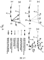
- the Figure 2 clarifies the procedure for each of the tillage implements 1-4.
- part A of the figure Figure 2 is determined at the location of the node E of the path I by comparison, which nodes in the map belong to locations that are close to the location of the node E. These neighboring locations N1, N2, N3 or nodes are indicated by dashed lines in part A of FIG Figure 2 visualized.
- the respective home vector H1, H2, H3 between the current location E and the neighboring location N1, N2, N3 is determined by local visual homing according to part B of the figure. These vectors represent the angle at which the neighboring location N appears relative to the direction of movement from the current location E.
- the distance value between location E and each neighboring location N can be calculated by triangulation.
- a respective distance vector AV represents the angle and the distance between location E and each neighboring location N.
- the value pairs of the distance value and angle of each neighboring location form input parameters for the navigation algorithm of the device in order to control the wheels as a function of this and thus the distance between the tracks To regulate I and II to a desired setpoint.
- the device travels essentially at a constant distance, in particular quasi "parallel" to the preceding lane II of another device.
- the navigation algorithm interprets the locations of this predecessor lane II as obstacles to be driven along, according to the navigation strategy stored in the algorithm.
Landscapes
- Engineering & Computer Science (AREA)
- Physics & Mathematics (AREA)
- Radar, Positioning & Navigation (AREA)
- Remote Sensing (AREA)
- General Physics & Mathematics (AREA)
- Automation & Control Theory (AREA)
- Aviation & Aerospace Engineering (AREA)
- Theoretical Computer Science (AREA)
- Databases & Information Systems (AREA)
- Data Mining & Analysis (AREA)
- General Engineering & Computer Science (AREA)
- Optics & Photonics (AREA)
- Electromagnetism (AREA)
- Multimedia (AREA)
- Library & Information Science (AREA)
- Mechanical Engineering (AREA)
- Computer Vision & Pattern Recognition (AREA)
- Control Of Position, Course, Altitude, Or Attitude Of Moving Bodies (AREA)
- Guiding Agricultural Machines (AREA)
Description
- Die Erfindung betrifft ein Verfahren zur Navigation wenigstens eines selbstfahrenden Bodenbearbeitungsgerätes, bevorzugt einer Vielzahl von Bodenbearbeitungsgeräten, die gleichzeitig einen Boden bearbeiten, d.h. zeitlich parallel, wobei die Antriebe eines jeweiligen Bodenbearbeitungsgerätes angesteuert werden in Abhängigkeit von Hindernisinformationen von durch das jeweilige Bodenbearbeitungsgerät detektierten Hindernissen, wobei Hindernisse zumindest gebildet werden durch reale Objekte, wie z.B. Wände, deren Hindernisinformationen durch Sensoren am jeweiligen Bodenbearbeitungsgerät erfasst werden, und wobei ein jeweiliges Bodenbearbeitungsgerät in zeitlichen und/oder räumlichen Abständen an Orten entlang der Bewegungsbahn mit einer mitgeführten Kamera Umgebungsbilder erfasst.
- Eine Vielzahl von Bodenbearbeitungsgeräten, die zeitlich parallel arbeiten, kann so einen Schwarm von Bodenbearbeitungsgeräten ausbilden.
- Die Erfindung betrifft weiterhin auch ein Bodenbearbeitungsgerät zur Durchführung des Verfahrens.
- Das Dokument
US 2007/0027612 A1 beschreibt ein Verfahren zum Koordinieren mehrerer Fahrzeuge in den Durchgängen in einer Mine. Grundsätzlich wird das Verfahren auch für Büroräume als anwendbar benannt. AuchDE 10 2012 112 036 A1 beschreibt ein selbstfahrendes Bodenbearbeitungsgerät und ein Verfahren zur Navigation. - Selbstfahrende Bodenbearbeitungsgeräte sind im Stand der Technik in vielfältiger Ausführung bekannt. Typische Vertreter solcher Bodenbearbeitungsgeräte sind Staubsaugroboter, Boden-Wischroboter oder Rasenmähroboter. Die Erfindung kann sich auf jeglichen Typ solcher Bodenbearbeitungsgeräte beziehen und bevorzugt auf Staubsaugroboter.
- Die Bodenbearbeitungsgeräte weisen jeweils angesteuerte, insbesondere geregelte Antriebe auf, damit sich diese Bodenbearbeitungsgeräte selbsttätig über die jeweilige Bodenfläche bewegen können. Diese Antriebe umfassen typischerweise zwei unabhängig ansteuerbare Räder und eine frei drehbare Lenkrolle oder Kugel, wobei Kurvenfahrten durch Ansteuerung der Räder mit unterschiedlichen Drehgeschwindigkeiten erfolgen, insbesondere somit eine sogenannte differentielle Lenkung vorliegt. Die Ansteuerung erfolgt mit einer in einem Gerät integrierten Elektronik, welche die Navigation des Gerätes auf einer Bodenfläche übernimmt, z.B. in Abhängigkeit von Sensorsignalen oder berechneten Werten.
- Typische Bodenbearbeitungsgeräte können dabei einen Gerätekörper mit z.B. kreisförmigem Grundriss aufweisen, wobei unterseitig, insbesondere zwischen den Rädern, eine Bodenbearbeitungsvorrichtung in den Gerätekörper integriert ist, z.B. eine Staubsaugvorrichtung oder eine rotierende Schneidvorrichtung.
- Die angetriebenen Räder können Radsensoren aufweisen, um für die Navigation eines solchen Gerätes Odometrie-Daten bereitzustellen, also z.B. konkret zurückgelegte Wegstrecken.
- Die sich bevorzugt nur in einer Ebene bewegenden Geräte weisen zur Hindernisdetektion im Rahmen der Navigation geeignete Sensoren auf, z.B. Kollisionssensoren, die auf Berührung reagieren oder bevorzugt berührungslos arbeitende Sensoren, z.B. ausgebildet als Laserscanner.
- Hier ist es bekannt, einen in einer horizontalen Ebene rotierenden Laser einzusetzen, um winkelabhängig Abstandswerte zu Hindernissen zu erfassen, oder auch eine feste Anzahl von Laserstrahlen, die alle in einer bevorzugt gemeinsamen horizontalen Ebene vom Gerät ausgehen, um mit jedem dieser Strahlen unter dann festgelegten Winkeln relativ zur Bewegungsrichtung des Gerätes mehrere Abstandswerte zu einem jeweiligen Hindernis oder auch zu mehreren Hindernissen zu ermitteln.
- In Abhängigkeit von derart sensorisch ermittelten Hindernisinformationen, die also bevorzugt durch mehrere Wertepaare von Winkeln und Abstand gegeben sind, kann ein Bodenbearbeitungsgerät bevorzugt kollisionsfrei navigieren, insbesondere eine erste Art der Navigation durchführen.
- Im Stand der Technik ist es bekannt, in der steuernden Elektronik eines solchen Gerätes einen Navigationsalgorithmus zu implementieren, mit dem eine sogenannte Wandverfolgung an einer realen Wand z.B. eines Raumes oder die Verfolgung eines sonstigen realen Hindernisses erfolgen kann, was bevorzugt bedeutet, dass das Gerät in einem geregelten Abstand parallel zu einer Erstreckung des Hindernisses, wie einer Wand, entlangfährt. Weiterhin ist es bekannt, dass sich ein solches Gerät frei im Raum auf einer z.B. geraden Bahn bewegt, bis es auf ein Hindernis stößt und umkehrt.
- Im bisherigen Stand der Technik ist die Art der gefahrenen Bewegungsbahn in der Elektronik vorgegeben implementiert, üblicherweise als Mäanderbahn oder als Spiralbahn. Bei einer vorgegebenen Mäanderbahn bedeutet dies, dass ein Bodenbearbeitungsgerät bei einem vor sich erkannten Hindernis seine Bewegungsrichtung umkehrt und in einem Abstand zu seiner eigenen zuvor gefahrenen Bahn zurückfährt. Dabei spielt es keine Rolle, ob die zuvor gefahrene Bahn an einer Wand entlang verlief oder frei im Raum entstanden ist.
- Bei einem solchen Navigationsalgorithmus zum Fahren entlang von einem oder mehreren Hindernissen, der im Stand der Technik und dem Fachmann grundsätzlich hinlänglich bekannt ist, werden Wertepaare von Winkel (unter welchem das Gerät das Hindernis "sieht") und Abstand (unter diesem Winkel) z.B. vom Gerätemittelpunkt bis zum Hindernis an den Algorithmus übergeben, wobei der Algorithmus sodann einen Abstandswert zum Hindernis quer, bevorzugt senkrecht zur Bewegungsrichtung berechnet, sofern er sich nicht sensorisch ebenso ergibt, und durch Steuerung der Antriebe der Räder auf einen Sollwert regelt.
- Im Stand der Technik ist es auch bekannt, eine Navigation durch sogenanntes lokales visuelles Homing durchzuführen. Lokales visuelles Homing ist eine Bezeichnung für eine Gruppe von Verfahren bei denen aus zwei Bildern, die an verschiedenen Orten aufgenommen wurden, ein Vektor, der sogenannte Home-Vektor berechnet wird, der von dem Ort, an dem eines der Bilder aufgenommen wurde, die Richtung zum Ort angibt, an dem das andere Bild aufgenommen wurde. Der Abstand zwischen beiden Orten wird nicht berechnet.
- Bei Vorliegen mehrerer, z.B. einer Vielzahl von Bildern, kann durch Triangulation anhand von wenigstens zwei Home-Vektoren unter Verwendung bekannter Abstände zwischen den Orten eine Bestimmung eines Abstandes des Gerätes, z.B. zu einer Bahn, erfolgen, entlang der das Bodenbearbeitungsgerät bereits gefahren ist und entlang der es selbst mehrere Bilder aufgenommen hat.
- Es besteht so die Möglichkeit eine Navigation auch anhand von Umgebungsbildern vorzunehmen, die an Orten aufgenommen wurden, an denen ein Bearbeitungsgerät schon einmal war. Unterschiedliche Arten, ein lokales visuelles Homing durchzuführen, sind im Stand der Technik und dem Fachmann ebenso hinlänglich bekannt.
- Im Dokument
DE 10 2007 016 802 B3 wird z.B. beschrieben, wie ein Bodenbearbeitungsgerät anhand von Umgebungsbildern, die auf seiner eigenen mäanderförmig oder spiralig vorgegebenen Bewegungsbahn aufgenommen wurden, und dem Verfahren des lokalen visuellen Homing durch Triangulation anhand von berechneten Home-Vektoren eine Abstandsregelung zu seiner eigenen Vorgängerbahn durchführt. - Da das Homing-Verfahren mit den vom Gerät selbst aufgenommenen Umgebungsbildern erfolgt und das Gerät eine vorgegebene, hier mäanderförmige Bahn fährt, ist es dem Gerät bekannt, welche der Umgebungsbilder es jeweils für die Triangulation und Abstandsregelung auf seinem neuen Bahnabschnitt zu verwenden hat, denn bei einer Richtungsumkehr fährt das Gerät an den Orten in umgekehrter Reihenfolge vorbei, an denen es auf der vorhergehenden Bahn Umgebungsbilder aufgenommen hat. Die Auswahl der heranzuziehenden Bilder erfolgt hier anhand von absoluten metrischen Informationen, über welche auf die benötigten Bilder zugegriffen wird.
- Das Vorgeben der z.B. mäanderförmigen Bahn erfolgt im Stand der Technik dadurch, dass ein Punkt auf der zu fahrenden Bahn bestimmt wird, den das Bodenbearbeitungsgerät von seinem aktuellen Ort aus anfahren soll und das Bodenbearbeitungsgerät entsprechend gesteuert wird, um den Punkt zu erreichen. Um den Punkt festzulegen ist es nötig, die Art der zu fahrenden Bahn in der Elektronik des Gerätes abgelegt zu haben. Jeder anzufahrende Punkt muss dem Kriterium genügen, auf der vorgegebenen Bahn zu liegen. So setzt sich eine Bahn aus einer Vielzahl von Vorgabepunkten zusammen, die nacheinander angefahren werden.
- Auf diese Weise kann eine z.B. mäanderförmige Navigation in jeweils parallelen vorgegebenen Bahnen, z.B. ausgehend von einer Bahn parallel zu einem Wandhindernis erfolgen, selbst wenn durch die Abstandsensoren das ursprünglichen Wandhindernis wegen zu großer Entfernung nicht mehr "gesehen" wird, oder auch ausgehend von einer frei im Raum liegenden Bahn erfolgen.
- Aus diesem Grund werden häufig die sensorbasierte Navigation anhand von Hindernisinformationen (Winkel, Abstand) und lokales visuelles Homing in Bodenbearbeitungsgeräten kombiniert. Die Navigation um Hindernisse herum setzt dabei im Stand der Technik kurzzeitig die ansonsten vorherrschende Bahnvorgabe außer Kraft.
- Sowohl bei der weiterhin hier beschriebenen Erfindung als auch im Stand der Technik wird zum Zweck der Navigation durch lokales visuelles Homing bevorzugt auf Umgebungsbilder zurückgegriffen, die ein 360°-Panorama der Umgebung des Ortes darstellen, an dem das Umgebungsbild aufgenommen wird. Dafür kann z.B. die vertikal ausgerichtete optische Achse einer Kamera auf den Mittelpunkt eines hyperbolischen Spiegels ausgerichtet sein, so dass im Kamerabild ein horizontales 360°-Panoramabild erfasst wird.
- Im Stand der Technik, insbesondere bei dem vorzitierten Stand der Technik, wird es als nachteilig angesehen, dass eine Homing-basierte Navigation nur mit akzeptabler Rechenkapazität der Bodenbearbeitungsgeräte erfolgen kann, wenn die zu navigierende Bahn, wie oben beschrieben, vorbekannt ist und sich insofern aus der Bekanntheit ergibt, welche Umgebungsbilder von vorherigen Bahnpunkten für das durchzuführende lokale visuelle Homing heranzuziehen sind. Beliebige Bahnformen können demnach im Stand der Technik nicht erschlossen werden.
- Auch setzt das bekannte Vorgehen dieses Standes der Technik voraus, dass das Bodenbearbeitungsgerät an seiner eigenen zuvor gefahrenen Bahn vorbeifährt, da ansonsten keine Umgebungsbilder identifiziert werden können, anhand derer ein Homing durchgeführt werden kann.
- Bei einem Einsatz von ggfs. mehreren Bodenbearbeitungsgeräten auf derselben Bodenfläche würde es somit oft zur Mehrfachbearbeitung derselben Flächenbereiche durch unterschiedliche Bodenbearbeitungsgeräte kommen, was unnötigen Aufwand verursacht.
- Vor diesem Hintergrund ist es eine Aufgabe der Erfindung, ein Navigationsverfahren zu erschließen, mit dem beliebige Bahnen der Bewegung eines Bodenbearbeitungsgerätes möglich sind, bevorzugt ein solches Verfahren geschaffen wird, bei dem für die Durchführung eines lokalen visuellen Homing eines Bodenbearbeitungsgerätes nicht auf durch die Bahn vorbestimmte Umgebungsbilder desselben Bodenbearbeitungsgerätes zurückgegriffen werden muss, sondern beliebige Bilder in der näheren Umgebung des Bodenbearbeitungsgerätes herangezogen werden können, unabhängig davon, welchen Ursprungs diese Umgebungsbilder sind.
- Insbesondere ist es eine Aufgabe der Erfindung, ein Verfahren zu erschließen, bei dem eine Bodenfläche auch durch mehrere Bodenbearbeitungsgeräte zeitlich parallel bearbeitet werden kann, ohne dass es zu Mehrfachbearbeitungen eines oder mehrerer Flächenbereiche kommt.
- Erfindungsgemäß wird diese Aufgabe dadurch gelöst, dass gemäß einem ersten Aspekt der Erfindung in einer Datenbank eine topologische Karte gebildet wird, in die von einem jeweiligen Bodenbearbeitungsgerät für jeden Ort, an dem ein Umgebungsbild, bevorzugt ein 360°-Panoramabild erfasst wird, ein Knoten eingefügt wird, dem zumindest das Umgebungsbild zugeordnet wird, und zwischen einem neu eingefügten Knoten und wenigstens einem in der Karte bestehenden, von demselben Bodenbearbeitungsgerät schon eingefügten Knoten Verbindungen gebildet werden, denen relative metrische Informationen zugeordnet werden.
- Gemäß diesem Aspekt wird erfindungsgemäß eine bevorzugt rein topologische Karte aufgebaut, anhand derer die Navigation zusätzlich zur Navigation mittels Hindernissensoren durchgeführt werden kann, insbesondere auch hier auf der Basis von lokalem visuellen Homing.
- Im Sinne der Erfindung wird unter einer rein topologischen Karte ein Graph im mathematischen Sinne verstanden, in welchem die Knoten Orte im Raum anhand von dort aufgezeichneten Sensordaten, hier zumindest das Panorama-Kamerabild charakterisieren, wobei Verbindungen, auch als Kanten bezeichnet, zwischen den Knoten eine wechselseitige Erreichbarkeit anzeigen. In solchen Verbindungen werden hier relative metrische Informationen über die relative Lage der Orte z.B. aus Odometriedaten gespeichert.
- Jeder Knoten der erfindungsgemäß aufzubauenden oder aufgebauten Karte repräsentiert demnach durch das zugeordnete Umgebungsbild einen Ort, an dem ein Bodenbearbeitungsgerät einmal war, ohne den Ort mit absoluten Koordinaten zu versehen. Verbindungen zwischen Knoten bedeuten eine Erreichbarkeit zwischen den Orten, die von den Knoten repräsentiert werden. Solche Verbindungen gibt es somit zumindest zwischen den Knoten, die für solche Orte in die Karte eingefügt werden, entlang denen ein jeweiliges Bodenbearbeitungsgerät gefahren ist.
- Die den Verbindungen zugeordneten relativen metrischen Informationen können bevorzugt durch die odometrischen Daten gebildet werden, die z.B. durch die Radsensoren des jeweiligen Bodenbearbeitungsgerätes erfasst werden, welches den Eintrag eines Knotens in die Karte veranlasst oder selbst vornimmt.
- Die Berücksichtigung lediglich relativer metrischer Informationen, insbesondere relativer Positionsinformationen und der Verzicht auf absolute Positionsinformationen ist hier ein entscheidender Vorteil der topologischen Karte, besonders, wenn mehrere Bodenbearbeitungsgeräte gemeinsam eine solche topologische Karte aufbauen, da sich die Bodenbearbeitungsgeräte nicht auf ein gemeinsames Koordinatensystem einigen müssen. Für die Durchführung des erfindungsgemäßen Verfahrens existiert somit kein absolutes externes bzw. "globales" Koordinatensystem, insbesondere für mehrere Bodenbearbeitungsgeräte kein gemeinsames Koordinatensystem.
- Für den erfindungsgemäßen Aufbau der topologischen Karte ist es dabei gänzlichst irrelevant, ob das Verfahren nur mit einem einzigen Bodenbearbeitungsgerät durchgeführt wird oder durch mehrere gleichzeitig. Jedes am Verfahren teilnehmende Bodenbearbeitungsgerät - also ggfs. auch nur eines - trägt Knoten in die Karte ein, für jeden Ort, an dem es Umgebungsbilder aufgenommen hat.
- Gemäß einem weiteren wesentlichen Aspekt der Erfindung wird, nachdem ein Bodenbearbeitungsgerät einen Knoten in die Karte eingetragen hat und das Umgebungsbild zugeordnet ist, durch Vergleich des neuen Umgebungsbildes am aktuellen Ort mit allen in der Datenbank schon zu Knoten zugeordneten Umgebungsbildern ermittelt, ob in einer begrenzten (räumlichen) Umgebung des zum neuen Umgebungsbild gehörenden aktuellen Orts sich wenigstens ein Nachbarort befindet, zu dem bereits ein Knoten und ein zugeordnetes Umgebungsbild in der Karte von demselben oder einem anderen Bodenbearbeitungsgerät gespeichert wurde.
- Die vorbenannte Ermittlung von Nachbarorten ist auf solche Orte beschränkt, die sich in einer festgelegten räumlichen Umgebung befinden, wobei die Umgebung nicht durch metrische räumliche Daten festgelegt sein muss. Vielmehr kann es vorgesehen sein, dass beim Bildvergleich ein bildliches (d.h. nicht räumliches) Abstandmaß zwischen aktuellem Umgebungsbild und allen schon gespeicherten ermittelt wird und ein Ort nur dann als Nachbarort gewertet wird, wenn das bildliche Abstandsmaß einen Schwellwert unterschreitet. Dem liegt die Überlegung zugrunde, dass mit abnehmendem räumlichen Abstand der Orte auch das bildliche Abstandsmaß der zugehörigen Umgebungsbilder abnimmt, demnach also Umgebungsbilder, die zum aktuellen Umgebungsbild das vorgegebene Abstandsmaß unterschreiten, zu Orten gehören, die einen bestimmten räumlichen - wenn auch nicht numerisch festgelegten - Abstand unterschreiten.
- Der wesentliche Vorteil dieses Verfahrensaspektes ist es, dass unabhängig von jeglicher Bahnform durch den Vergleich ermittelt werden kann, ob ein Bodenbearbeitungsgerät in der Nähe eines Ortes oder mehrerer Orte ist, der oder die schon bearbeitet wurde/n und zwar ebenso unabhängig davon, ob diese Bearbeitung durch das Bodenbearbeitungsgerät selbst (welches das aktuelle Umgebungsbild lieferte) oder durch ein anderes zeitlich parallel arbeitendes Bodenbearbeitungsgerät in die Datenbank bzw. die topologische Karte eingetragen wurde. Da der Vergleich für jedes neu zu einem Knoten zugeordnete Umgebungsbild und für alle Bestandsbilder durchgeführt wird, können demnach auch mehrere Nachbarorte gefunden werden, die das Vergleichskriterium erfüllen, also einen Nachbarort in begrenzter Umgebung bilden.
- Die Erfindung sieht nun vor, dass bei Vorhandensein wenigstens eines solchen durch Vergleich gefundenen Nachbarortes ausgehend vom neu eingefügten Knoten zu dem zugehörigen Knoten jedes ermittelten Nachbarortes in der topologischen Karte eine neue Verbindung eingefügt wird, wodurch die topologische Karte durch Erreichbarkeitsinformationen zwischen den Orten ergänzt wird.
- Ein weiterer wesentlicher Aspekt der Erfindung ist es, dass zu wenigstens einem, bevorzugt allen Nachbarorten zu deren Knoten neue Verbindungen in die Karte eingefügt wurden, Hindernisinformationen relativ zum aktuellen Ort des neuen Umgebungsbildes aus den in der Karte gespeicherten Daten berechnet, in Form relativer metrischer Beziehungen in den Verbindungen eingetragen und zur Steuerung oder Regelung der Antriebe des jeweiligen Bodenbearbeitungsgerätes herangezogen werden. Diese Hindernisinformationen können auch hier wiederum Werte von Winkel und Abstand, berechnet durch lokales visuelles Homing, sein zwischen dem aktuellen Ort und jedem der vorangehend durch Vergleich gefundenen Nachbarorte.
- Für die Erfindung bedeutet dies, dass in bevorzugter Ausführung ein jeder durch Vergleich gefundene Nachbarort bei der Navigation wie ein Hindernis, nämlich wie ein virtuelles Hindernis gewertet werden kann, welches durch einen Winkelwert und einen Abstandswert relativ zum aktuellen Ort charakterisiert ist, so als wäre das Hindernis sensorisch ausgemessen worden, wie es bei realen Hindernissen z.B. mittels Hindernissensoren, z.B. Laser erfolgt, was eingangs beschrieben wurde.
- Erfindungsgemäß kann es dabei vorgesehen sein, dass an einen Navigationsalgorithmus, wie er in seiner Art zur eingangs beschriebenen realen Wandverfolgung bekannt ist, Wertepaare von Winkel und Abstand übergeben werden und dieser Algorithmus in Abhängigkeit dieser Werte die Antriebe bzw. Räder des jeweiligen Bodenbearbeitungsgerätes ansteuert, insbesondere auf einen bestimmten Abstand zum virtuellen Hindernis regelt. Erfindungsgemäß kann es sogar vorgesehen sein, dass exakt an denselben Navigationsalgorithmus die Wertepaare von Winkel und Abstand als Steuergröße übergeben werden, der auch die Navigation für reale Hindernisse vornimmt. Die Navigation bzw. der dafür hinterlegte Algorithmus unterscheidet demnach nicht zwischen den Hinderniswerten von realen oder virtuellen Hindernissen.
- Gemäß dieser im Stand der Technik grundsätzlich bekannten Navigationsart werden somit die erfindungsgemäß ermittelten virtuellen Hindernisse so behandelt, als seien es reale Hindernisse, mit dem Effekt, dass Bodenbereiche, die von einem beliebigen Bodenbearbeitungsgerät bereits bearbeitet wurden, als virtuelles Hindernis von jedem Bodenbearbeitungsgerät umfahren werden.
- Die Abstandsregelung zum virtuellen Hindernis, also einem jeweils gefundenen Nachbarort, kann dabei genauso erfolgen wie bei der Abstandregelung zum realen Hindernis, wie einer Wand.
- Aufgrund der Navigation eines Bodenbearbeitungsgerätes anhand von realen und virtuellen Hindernissen wird die im Augenblick zu fahrende Bahn nicht durch anzufahrende Punkte gemäß einer Bahnvorgabe geplant und erzielt, sondern die Bahn ergibt sich situationsbedingt anhand der vorliegenden Hindernisse, an denen in einem festgelegten Abstand entlanggefahren wird. Die Erfindung sieht dabei bevorzugt vor, die Bodenbearbeitung entlang von realen Hindernissen zu starten.
- Eine Ausführung kann hier bevorzugt vorsehen, dass bei einer Regelung relativ zu einem virtuellen Hindernis ein anderer, bevorzugt größerer Abstandswert als Sollwert in der Regelung vorgegeben wird im Vergleich zur Regelung bei realen Hindernissen, insbesondere um hierdurch zu berücksichtigen, dass ein Bodenbearbeitungsgerät wegen der schon erfolgten Bearbeitung des Bodens am virtuellen Hindernis (Nachbarort) in einem größeren Abstand vorbeifahren kann als dies an einem realen Hindernis der Fall wäre, an welches möglichst nahe heranzufahren ist.
- Alternativ kann es vorgesehen sein, ermittelte Abstandswerte eines jeweiligen Wertepaares von Winkel und Abstandswert zwischen aktuellem Ort und einem durch Vergleich ermittelten Nachbarort durch einen Faktor zu skalieren, insbesondere so dass einem Bodenbearbeitungsgerät der Abstand kleiner erscheint als er tatsächlich ist. In diesem Fall kann immer auf denselben Abstandswert zwischen Gerät und Hindernis (betrachtet senkrecht zur Bahn des Gerätes) bei der Navigation geregelt werden, ohne zwischen realen und virtuellen Hindernissen unterscheiden zu müssen.
- Es kann so erfindungsgemäß jeweils erzielt werden, dass sich ein jeweiliges Bodenbearbeitungsgerät in einem Abstand entlang solcher Orte weiterbewegt, deren Knoten/Umgebungsbilder in der topologischen Karte ausgehend von einem Knoten eines festgestellten Nachbarortes Verbindungen mit metrischen, bevorzugt odometrischen Informationen aufweisen.
- Dies kann erzielt werden, da zu jedem dieser verbundenen Orte Nachbarschaftsbeziehungen im Sinne des zuvor genannten Vergleiches bestehen. Es kann so ein Bodenbearbeitungsgerät neben einer schon bearbeiteten Bahn z.B. parallel in einem geregelten Abstand entlangfahren, wobei dies wegen der vorteilhaften Wirkungen der Erfindung sowohl bei Bahnen erfolgen kann, die dasselbe Bodenbearbeitungsgerät schon gefahren ist, ebenso wie bei Bahnen von einem anderen Bodenbearbeitungsgerät.
- Bei Teilnahme von mehreren gleichzeitig arbeitenden Bodenbearbeitungsgeräten ist es bevorzugt vorgesehen, dass die Umgebungsbilder aller Bodenbearbeitungsgeräte zur Erzeugung einer einzigen gemeinsamen topologischen Karte gespeichert werden in einer einzigen gemeinsamen Datenbank auf einer zentralen Datenverarbeitungsanlage und/oder in einer für jedes Bodenbearbeitungsgerät individuellen Datenbank auf dem jeweiligen Bodenbearbeitungsgerät, insbesondere wobei die Inhalte aller individuellen Datenbanken identisch sind oder jede individuelle Datenbank nur einen Teil der gemeinsamen Karte umfasst.
- Die Erfindung kann hier vorsehen, dass die Umgebungsbildunterkante, bevorzugt Panoramabildunterkante eine solche Höhe aufweist, dass sich die mehreren Bodenbearbeitungsgeräte nicht selbst in den Umgebungsbildern erfassen.
- Zur Vermeidung von Kollisionen der Bodenbearbeitungsgeräte untereinander kann hingegen eine gegenseitige sensorische, ggfs. gegenseitige visuelle Erfassung der Bodenbearbeitungsgeräte vorgesehen sein, insbesondere auch über die Kamera, mit welcher jeweils Umgebungsbilder erfasst werden.
- In jeder dieser Ausführungen gibt es nur eine einzige rein topologische Karte, in welche alle teilnehmenden Bodenbearbeitungsgeräte Knoten einfügen und Umgebungsbilder zugeordnet werden und auch alle Bodenbearbeitungsgeräte die zur Navigation benötigten Daten aus dieser einen topologischen Karte beziehen.
- Obgleich die Bodenbearbeitungsgeräte bei Ausbildung einer zentralen Datenbank nicht untereinander kommunizieren müssen, greifen alle auf dieselben Daten zu, so dass jedes Bodenbearbeitungsgerät hierdurch Kenntnis erhalten kann (durch Nachbarortermittlung) von Bereichen, wo es selbst oder ein anderes bereits war.
- Eine Weiterbildung kann hier vorsehen, dass die Umgebungsbilder mittels einer drahtlosen Kommunikation von einem jeweiligen Bodenbearbeitungsgerät (von mehreren) zu der einzigen gemeinsamen Datenbank oder den jeweiligen individuellen Datenbanken kommuniziert werden, insbesondere jedes Bodenbearbeitungsgerät hierfür mit der zentralen Datenverarbeitungsanlage oder mit jedem anderen Bodenbearbeitungsgerät kommuniziert.
- Der Vergleich eines aktuellen Umgebungsbildes eines jeden Bodenbearbeitungsgerätes erfolgt erfindungsgemäß mit allen in der gemeinsamen Datenbank gespeicherten Umgebungsbildern auf der zentralen Datenverarbeitungsanlage, wobei die Ermittlung der eingangs genannten Hindernisinformationen zu jedem gefundenen Nachbarort in bevorzugter Ausführung unter Einsatz von lokalem visuellen Homing erfolgt, bevorzugt zwischen dem aktuellen Ort und zu mehreren Nachbarorten, um mehrere Home-Vektoren zu ermitteln, aus denen sich die Winkelwerte zwischen den Orten ergeben, und um mit diesen und relativer Positionsinformation durch Triangulation auch Abstände zwischen den Orten zu bestimmen.
- Die Erfindung kann vorsehen, dass ermittelte relative Positionsinformationen zwischen den Orten denjenigen Verbindungen zugeordnet werden, die zwischen den jeweiligen Knoten dieser Orte in der topologischen Karte bestehen, so dass bei einer erneuten Verwendung solcher Orte und Knoten unmittelbar auf die in den Verbindungen gespeicherten Werte zugegriffen werden kann, ohne dass diese Werte erneut berechnet werden müssen.
- Bei Verwendung von mehreren Bodenbearbeitungsgeräten kann die Erfindung vorsehen, dass die Berechnungen und Zuordnungen von Werten (Abstand /Winkel) auf der zentralen Datenbank bzw. einer diese verwaltenden Datenverarbeitungsanlage erfolgt und die Werte an dasjenige Bodenbearbeitungsgerät zurückübermittelt werden, welches das aktuelle Panoramabild für den Vergleich lieferte, so dass dieses jeweilige Gerät die Wertepaare an seinen Navigationsalgorithmus übergeben kann.
- Die Erfindung kann hingegen auch vorsehen, dass von jedem Bodenbearbeitungsgerät individuell selbst der Vergleich eines aktuellen Umgebungsbildes mit den in der jeweiligen individuellen Datenbank gespeicherten Umgebungsbildern vorgenommen wird und selbst die Hindernisinformationen ermittelt werden.
- Unabhängig davon, ob das Verfahren mit nur einem oder mit mehreren Bodenbearbeitungsgeräten durchgeführt wird, kann es vorgesehen sein, dass der Vergleich eines neuen Umgebungsbildes mit allen anderen gespeicherten Umgebungsbildern zum Ermitteln von Nachbarorten in zwei Stufen erfolgt.
- Dabei kann es vorgesehen sein, dass in einer ersten Stufe eine Gruppe von Umgebungsbildern ermittelt wird, die bei einem Vergleich mit dem neuen Umgebungsbild einem ersten Vergleichskriterium genügen --- z.B. wobei der Vergleich weniger streng ist und/oder schneller berechenbar ist gegenüber der zweiten Stufe ---und in einer zweiten Stufe aus der Gruppe der in der ersten Stufe ermittelten Umgebungsbilder solche Umgebungsbilder ermittelt werden, die beim Vergleich mit dem neuen Umgebungsbild einem zweiten Vergleichskriterium genügen, z.B. wobei der Vergleich strenger und aufwändiger zu berechnen ist gegenüber der ersten Stufe. Ein solches Vorgehen kann auch in mehr als zwei Stufen erfolgen.
- Für den Vergleich in erster Stufe müssen nicht die gesamten Bilddaten eines jeweiligen Bildes herangezogen werden. Es kann vorgesehen sein, zu jedem Bild eine Bildsignatur zu erstellen, die den Bildinhalt repräsentiert, und die Signaturen der Bilder zu vergleichen.
- Hierdurch kann der Vorteil erschlossen werden, dass in der ersten Stufe eine schnelle und grobe Vorauswahl von Nachbarorten erfolgt, die zu einer Gruppe zusammengefasst werden, und sodann erst eine genauere und zeitlich aufwändigere Prüfung auf ein Nachbarschaftsverhältnis nur innerhalb der vorausgewählten Gruppe erfolgt.
- Eine beispielshafte Ausführung kann hier vorsehen, dass in der ersten Stufe beim aktuellen Umgebungsbild Gruppen von mehreren Bildzeilen zu jeweils einer Zeile gemittelt werden und nach einer Fouriertransformation jeder gemittelten Zeile ein Abstandsmaß von den Absolutbeträgen der Fourierkoeffizienten dieses aktuellen Umgebungsbildes und den korrespondierenden Absolutbeträgen der Fourierkoeffizienten gespeicherter Umgebungsbilder gebildet wird und aus den gespeicherten Bildern eine Gruppe von Umgebungsbildern selektiert wird, bei denen die gebildeten Abstandsmaße jeweils einen Schwellwert unterschreiten.
- In diesem Fall bilden die Absolutbeträge der Fourierkoeffizienten die zuvor genannte Signatur.
- Die Erfindung kann hier auch vorsehen, dass bereits bei der Eintragung von Knoten in die Karte und Zuordnung des Umgebungsbildes die später für den Vergleich heranzuziehende Signatur gespeichert wird. Für jeden Knoten und das zugeordnete Bild in der topologischen Karte besteht somit bereits anfänglich eine Signaturinformation, auf die jederzeit zugegriffen werden kann.
- Auch hier wird unter einem Abstandsmaß ein Maß verstanden, das Bildunterschiede zwischen den Bildern repräsentiert und nicht einen räumlichen Abstand. Das Abstandsmaß kann z.B. ein euklidisches sein.
- Das Verwerfen von Phaseninformationen und ledigliches Berücksichtigen von Absolutbeträgen der Fourierkoeffizienten hat den Vorteil, dass die hier zum Vergleich herangezogenen Bildinformationen rotationsinvariant sind und somit die zu vergleichenden Bilder nicht erst über einen Bildkompass rechnerisch ausgerichtet werden müssen.
- Die Erfindung kann dann weiter vorsehen, dass in der zweiten Stufe ein Abstandsmaß (z.B. euklidisch) vom aktuellen Umgebungsbild zu jedem Umgebungsbild der in erster Stufe selektierten Gruppe gebildet wird, insbesondere wobei die Berechnung des Abstandsmaßes bei zwei Umgebungsbildern mehrfach unter Drehung eines der Umgebungsbilder in Azimuthrichtung um einen Winkelbetrag wiederholt wird und das Minimum aller Abstandsmaße als resultierendes Abstandsmaß gewählt wird, wobei die Umgebungsbilder zu solchen Orten als Nachbarort selektiert werden, deren Abstandsmaß einen Schwellwert unterschreitet.
- Unabhängig davon, ob der Vergleich zwischen Umgebungsbildern zum Ermitteln von Nachbarorten mit dem hier genannten konkreten Verfahren erfolgt oder durch eine andere Art der Vergleichsdurchführung, sieht die Erfindung bevorzugt vor, nach der Ermittlung der Nachbarorte zu einem aktuellen Ort für jeden gefundenen Nachbarort die erfindungsgemäß benötigten Hindernisinformationen zu berechnen, also bevorzugt den Winkel und den Abstand, unter dem ein solcher Nachbarort vom aktuellen Ort aus durch das Bodenbearbeitungsgerät "gesehen" wird.
- Die Winkelwerte können dabei durch ein Verfahren zum lokalen visuellen Homing zwischen jedem Paar von aktuellem Ort und ermittelten Nachbarort berechnet werden, da der Home-Vektor den Winkel repräsentiert.
- Hier kann in bevorzugter Ausführungsvariante ein lokales visuelles Homing anhand von Warping-Methoden, z.B. Min-Warping durchgeführt werden. Dabei werden ausgehend von einem Umgebungsbild (Ausgangsbild, z.B. aktuelles Umgebungsbild) Bilder berechnet, die ein Bodenbearbeitungsgerät aufnehmen ("sehen") würde, wenn es sich bewegt hätte, wobei die berechneten Bilder verglichen werden mit dem Zielbild, z.B. Bild am Nachbarort; die Bilder müssen jedoch nicht unbedingt explizit berechnet werden. Der Vergleich kann erfolgen anhand der angenommenen Bewegungsparameter, wobei der Home-Vektor bestimmt wird aus denjenigen Bewegungsparametern, die die beste Übereinstimmung liefern zwischen dem berechneten Bild und dem Zielbild. Ein solches Min-Warping-Verfahren hat den Vorteil, dass ein Azimuth-Ausgleich bei den zu vergleichenden Umgebungsbildern mittels eines Bildkompasses nicht stattfinden muss.
- Die metrischen Abstände zwischen dem aktuellen Ort und jedem Nachbarort können sodann durch Triangulation, insbesondere unter Einsatz von lokalem visuellem Homing, zwischen diesen Orten und aus der topologischen Karte hinzugezogenen weiteren Orten bzw. Knoten berechnet werden, insbesondere unter Einbeziehung von bereits in der Karte in Verbindungen der zugehörigen Knoten gespeicherten relativen metrischen Informationen.
- Neue metrische Abstandsinformationen, die hierbei zwischen zwei Orten berechnet werden, können erfindungsgemäß in Verbindungen der zugehörigen Knoten in der Karte gespeichert werden.
- Mit den so erhaltenen konkreten Wertepaaren von Winkel und Abstand für jedes Paar von aktuellem Ort und Nachbarort kann sodann die Navigation, d.h. die Ansteuerung der Antriebe der Räder eines jeweiligen Bodenbearbeitungsgerätes in Abhängigkeit von diesen Wertepaaren erfolgen, insbesondere unter Regelung des Abstandes zwischen der aktuell gefahrenen Bahn und einer durch die Nachbarorte identifizierten vorherigen Bahn.
- Ein erfindungsgemäßes selbstfahrendes Bodenbearbeitungsgerät umfasst gemäß den vorherigen Ausführungen eine Vorrichtung zur Bearbeitung eines Bodens, insbesondere eine Staubsaugvorrichtung, sowie mittels einer Elektronik angesteuerte Antriebe, wobei ein solches Gerät weiterhin eingerichtet ist, insbesondere die Elektronik programmiert ist, ein Verfahren der vorbeschriebenen Art auszuführen.
- Hierbei ist in der Elektronik bevorzugt ein Algorithmus in der Form eines durch einen Mikroprozessor abgearbeiteten Programmes implementiert, der die Antriebe der Räder des Gerätes in Abhängigkeit von Paaren von Abstandswerten und Winkelwerten ansteuert, welche die relative räumliche Beziehung zwischen dem Gerät und einem Hindernis repräsentieren. Dem Algorithmus bzw. diesen ausführenden Programmteil werden dabei alternativ oder sogar kumulativ Wertepaare von Abstand und Winkel zu realen Hindernissen (Gegenstände) und virtuellen Hindernissen übergeben, wobei letztere gebildet werden durch Orte, an denen ein Bodenbearbeitungsgerät bereits einmal war.
- Das Gerät ist dabei eingerichtet, auf eine rein topologische Karte in einer Datenbank Zugriff zu nehmen, in der für jeden solchen Ort ein Knoten gebildet ist.
- Das erfindungsgemäße Verfahren wird anhand der nachfolgenden Figuren näher beschrieben.
- Die
Figur 1 zeigt eine beispielshafte Wohnung mit mehreren Räumen, in der 4 Bodenbearbeitungsgeräte 1-4 gleichzeitig den Wohnungsboden bearbeiten, z.B. Staub saugen. - Alle Geräte 1-4 arbeiten mit demselben Navigationsverfahren und kommunizieren hier über Funk, z.B. WLAN, mit einer zentralen Datenbank 5, die auf einer Datenverarbeitungsanlage verwaltet wird und die eine topologische Karte mit Knoten zu allen Orten umfasst, an denen von jedem der Geräte 1-4 ein Panoramabild gemacht wurde. Diese Orte sind in der
Figur 1 durch Punkte 6 gekennzeichnet. Die Punkte weisen hier grafisch dargestellte Verbindungen auf, um die Bahnen der Bewegung eines jeden Bodenbearbeitungsgerätes 1 bis 4 zu kennzeichnen. - Hier ist erkennbar, dass es keine Bahnüberschneidungen gibt, was an dem erfindungsgemäßen Verfahren liegt, gemäß dem für jedes Bodenbearbeitungsgerät 1-4 an seinem aktuellen Ort geprüft wird, ob es Nachbarorte gibt, an denen irgendeines der Bodenbearbeitungsgeräte bereits zuvor war. Solche Orte werden als Hindernis erkannt und durch den Navigationsalgorithmus umfahren, gemäß den Erläuterungen im allgemeinen Teil der Beschreibung.
- Sofern ein Gerät nur noch von bereits befahrenen Bereichen, also virtuellen oder realen Hindernissen umgeben ist, sucht es noch freie unbearbeitete Bereiche, was durch eine Freiraumdetektion mittels der gespeicherten topologischen Karte erfolgen kann.
- Die
Figur 2 verdeutlicht die Vorgehensweise für jedes der Bodenbearbeitungsgeräte 1-4. - Hier sei angenommen, dass sich ein Gerät auf einem aktuellen Bahnabschnitt I befindet, der neben einem bereits befahrenen Bahnabschnitt II liegt. Die Punkte der Bahnabschnitte I und II repräsentieren Knoten in der topologischen Karte, denen Panoramabilder der zugehörigen Orte zugeordnet sind. Durchgezogene Verbindungen V zwischen Punkten eines jeweiligen Bahnabschnittes I oder II repräsentieren Verbindungen in der topologischen Karte, denen relative metrische Informationen aus Odometrie zugeordnet sind.
- Gemäß Figurenteil A der
Figur 2 wird am Ort des Knoten E der Bahn I durch Vergleich ermittelt, welche Knoten in der Karte zu Orten gehören, die nahe bei dem Ort des Knoten E liegen. Diese in Nachbarschaft stehenden Orte N1, N2, N3 bzw. Knoten sind durch gestrichelte Linien im Teil A derFigur 2 visualisiert. - Nach Feststellung dieser Orte N wird gemäß Figurenteil B durch lokales visuelles Homing der jeweilige Home-Vektor H1, H2, H3 zwischen aktuellem Ort E und Nachbarort N1, N2, N3 ermittelt. Diese Vektoren repräsentieren den Winkel, unter dem der Nachbarort N relativ zur Bewegungsrichtung vom aktuellen Ort E aus erscheint.
- Zusammen mit metrischen Informationen M in den Verbindungen der Nachbarorte N1, N2, N3, die aus der Karte ausgelesen werden können, kann durch Triangulation der Abstandswert zwischen Ort E und jedem Nachbarort N errechnet werden.
- Ein jeweiliger Abstandsvektor AV repräsentiert hiernach den Winkel und den Abstand zwischen Ort E und jedem Nachbarort N. Die Wertepaare von Abstandswert und Winkel jedes Nachbarortes bilden Eingangsparameter für den Navigationsalgorithmus des Gerätes, um in Abhängigkeit hiervon die Räder anzusteuern und um so den Abstand zwischen den Bahnen I und II auf einen gewünschten Sollwert zu regeln.
- Hierdurch fährt das Gerät im Wesentlichen im konstanten Abstand, insbesondere quasi "parallel" zur Vorgängerbahn II eines anderen Gerätes. Der Navigationsalgorithmus interpretiert die Orte dieser Vorgängerbahn II als Hindernisse, an denen es entlang zu fahren gilt, gemäß der in dem Algorithmus hinterlegten Navigationsstrategie.
Claims (11)
- Verfahren zur Navigation wenigstens eines selbstfahrenden Bodenbearbeitungsgerätes (1, 2, 3, 4), insbesondere wenigstens eines Staubsaugroboters (1, 2, 3, 4), bevorzugt einer Vielzahl von Bodenbearbeitungsgeräten (1, 2, 3, 4), wobei die Antriebe eines jeweiligen Bodenbearbeitungsgerätes (1, 2, 3, 4) angesteuert werden in Abhängigkeit von Hindernisinformationen von durch das jeweilige Bodenbearbeitungsgerät (1, 2, 3, 4) detektierten Hindernissen, insbesondere in Abhängigkeit von Werten für Abstand und Winkel zwischen dem jeweiligen Bodenbearbeitungsgerät (1, 2, 3, 4) und wenigstens einem Hindernis, wobei Hindernisse zumindest gebildet werden durch reale Objekte, insbesondere Wände, deren Hindernisinformationen durch Sensoren am jeweiligen Bodenbearbeitungsgerät (1, 2, 3, 4), insbesondere Laserscanner, erfasst werden und wobei ein jeweiliges Bodenbearbeitungsgerät (1, 2, 3, 4) in zeitlichen und/oder räumlichen Abständen an Orten (6) entlang der Bewegungsbahn mit einer mitgeführten Kamera Umgebungsbilder, insbesondere 360°-Panoramabilder erfasst, insbesondere anhand denen ein jeweiliges Bodenbearbeitungsgerät (1, 2, 3, 4) mittels visuellem Homing navigiert, dadurch gekennzeichnet, dassa. in einer Datenbank (5) eine topologische Karte gebildet wird, in die von einem jeweiligen Bodenbearbeitungsgerät (1, 2, 3, 4) für jeden Ort (E, 6), an dem ein Umgebungsbild erfasst wird, ein Knoten eingefügt wird, dem zumindest das Umgebungsbild zugeordnet wird, und zwischen einem neu eingefügten Knoten und wenigstens einem in der Karte bestehenden, von demselben Bodenbearbeitungsgerät (1, 2, 3, 4) schon eingefügten Knoten Verbindungen (V) gebildet werden, denen relative metrische Informationen zugeordnet werden, insbesondere die durch odometrische Daten des jeweiligen Bodenbearbeitungsgerätes (1, 2, 3, 4) ermittelt werden, undb. durch Vergleich des neuen Umgebungsbildes am aktuellen Ort (E), zu dem in die Karte ein neuer Knoten eingefügt wird, mit allen in der Datenbank schon zu Knoten zugeordneten Umgebungsbildern ermittelt wird, ob in einer begrenzten Umgebung des zum neuen Umgebungsbild gehörenden aktuellen Orts (E) sich wenigstens ein Nachbarort (N1, N2, N3) befindet, zu dem bereits ein Knoten und ein zugeordnetes Umgebungsbild in der Karte von demselben oder einem anderen Bodenbearbeitungsgerät (1, 2, 3, 4) gespeichert wurde undc. bei Vorhandensein wenigstens eines solchen Nachbarortes (N1, N2, N3) ausgehend vom neu eingefügten Knoten zu dem zugehörigen Knoten jedes ermittelten Nachbarortes (N1, N2, N3) in der topologischen Karte eine neue Verbindung eingefügt wird undd. zu wenigstens einem, bevorzugt allen Nachbarorten (N1, N2, N3) zu deren Knoten neue Verbindungen in die Karte eingefügt wurden, Hindernisinformationen, insbesondere mithilfe von visuellem Homing, relativ zum aktuellen Ort (E) des neuen Umgebungsbildes aus den in der Karte gespeicherten Daten berechnet und zur Steuerung oder Regelung der Antriebe des jeweiligen Bodenbearbeitungsgerätes (1, 2, 3, 4) herangezogen werden.
- Verfahren nach Anspruch 1, dadurch gekennzeichnet, dass sich ein jeweiliges Bodenbearbeitungsgerät (1, 2, 3, 4) in einem Abstand entlang solcher Orte weiterbewegt, deren Knoten/Umgebungsbilder in der topologischen Karte ausgehend von einem Knoten eines festgestellten Nachbarortes (N1, N2, N3) Verbindungen (V) mit metrischen, bevorzugt odometrischen Informationen aufweisen.
- Verfahren nach einem der vorherigen Ansprüche, dadurch gekennzeichnet, dass bei einer Vielzahl von gleichzeitig einen Boden bearbeitenden Bodenbearbeitungsgeräten (1, 2, 3, 4) die Umgebungsbilder aller Bodenbearbeitungsgeräte zur Erzeugung einer einzigen gemeinsamen topologischen Karte gespeichert werden ina. einer einzigen gemeinsamen Datenbank (5) auf einer zentralen Datenverarbeitungsanlage und/oderb. in einer für jedes Bodenbearbeitungsgerät individuellen Datenbank auf dem jeweiligen Bodenbearbeitungsgerät (1, 2, 3, 4) , insbesondere wobei die Inhalte aller individuellen Datenbanken identisch sind oder jede individuelle Datenbank nur einen Teil der gemeinsamen Karte umfasst.
- Verfahren nach Anspruch 3, dadurch gekennzeichnet, dass die Umgebungsbilder mittels einer drahtlosen Kommunikation von einem jeweiligen Bodenbearbeitungsgerät (1, 2, 3, 4) zu der einzigen gemeinsamen Datenbank (5) oder den jeweiligen individuellen Datenbanken kommuniziert werden, insbesondere jedes Bodenbearbeitungsgerät (1, 2, 3, 4) hierfür mit der zentralen Datenverarbeitungsanlage oder mit jedem anderen Bodenbearbeitungsgerät (1, 2, 3, 4) kommuniziert.
- Verfahren nach Anspruch 3 oder 4, dadurch gekennzeichnet, dass der Vergleich eines aktuellen Umgebungsbildes eines jeden Bodenbearbeitungsgerätes (1, 2, 3, 4) mit allen in der gemeinsamen Datenbank (5) gespeicherten Umgebungsbildern auf der zentralen Datenverarbeitungsanlage erfolgt und die insbesondere unter Anwendung von lokalem visuellem Homing ermittelten Hindernisinformationen bevorzugt zu mehreren Nachbarorten (N1, N2, N3) an dasjenige Bodenbearbeitungsgerät (1, 2, 3, 4) zurückübermittelt werden, welches das aktuelle Panoramabild für den Vergleich lieferte.
- Verfahren nach Anspruch 3 oder 4, dadurch gekennzeichnet, dass von jedem Bodenbearbeitungsgerät (1, 2, 3, 4) individuell selbst der Vergleich eines aktuellen Umgebungsbildes mit den in der jeweiligen individuellen Datenbank gespeicherten Umgebungsbildern vorgenommen wird und selbst die Hindernisinformationen ermittelt werden.
- Verfahren nach einem der vorherigen Ansprüche, dadurch gekennzeichnet, dass der Vergleich eines neuen Umgebungsbildes mit allen anderen gespeicherten Umgebungsbildern in zwei Stufen erfolgt, wobei in einer ersten Stufe eine Gruppe von Umgebungsbildern ermittelt wird, die bei einem Vergleich mit dem neuen Umgebungsbild einem ersten, insbesondere weniger strengen und schneller berechenbaren Vergleichskriterium genügen und in einer zweiten Stufe aus der Gruppe der in der ersten Stufe ermittelten Umgebungsbilder solche Umgebungsbilder ermittelt werden, die beim Vergleich mit dem neuen Umgebungsbild einem zweiten, insbesondere strengeren und aufwändiger zu berechnenden Vergleichskriterium genügen.
- Verfahren nach Anspruch 7, dadurch gekennzeichnet, dass in der ersten Stufe beim aktuellen Panoramabild Gruppen von mehreren Bildzeilen zu jeweils einer Zeile gemittelt werden und nach einer Fouriertransformation jeder gemittelten Zeile ein Abstandsmaß von den Absolutbeträgen der Fourierkoeffizienten und den korrespondierenden Absolutbeträgen der Fourierkoeffizienten gespeicherter Umgebungsbilder gebildet wird und aus den gespeicherten Bildern eine Gruppe von Umgebungsbildern selektiert wird, bei denen die gebildeten Abstandsmaße jeweils einen Schwellwert unterschreiten.
- Verfahren nach Anspruch 8, dadurch gekennzeichnet, dass in der zweiten Stufe ein Abstandsmaß vom aktuellen Umgebungsbild zu jedem Bild der selektierten Gruppe gebildet wird, insbesondere wobei die Berechnung des Abstandsmaßes bei zwei Umgebungsbildern mehrfach unter Drehung eines der Umgebungsbilder um einen Winkelbetrag in Azimuthrichtung wiederholt wird und das Minimum aller Abstandsmaße gewählt wird, wobei die Umgebungsbilder zu solchen Orten als Nachbarort (N1, N2, N3) selektiert werden, deren Abstandsmaß einen Schwellwert unterschreitet.
- Verfahren zur Navigation mehrerer selbstfahrender Bodenbearbeitungsgeräte (1, 2, 3, 4), wobei jedes der Bodenbearbeitungsgeräte (1, 2, 3, 4) dasselbe Navigationsverfahren ausführt, welches ein Wandverfolgungsverfahren umfasst, wobei eine zu verfolgende Wand gebildet wird sowohl durch eine reale Wand als auch eine virtuelle Wand, die gebildet wird durch Knoten in einer von allen Bodenbearbeitungsgeräten (1, 2, 3, 4) gemeinsam aufgebauten topologischen Karte nach einem der vorherigen Ansprüche.
- Selbstfahrendes Bodenbearbeitungsgerät (1, 2, 3, 4), umfassend eine Vorrichtung zur Bearbeitung eines Bodens, insbesondere umfassend eine Staubsaugvorrichtung, sowie mittels einer Elektronik angesteuerter Antriebe, dadurch gekennzeichnet, dass es eingerichtet ist, ein Verfahren nach einem der vorherigen Ansprüche auszuführen.
Applications Claiming Priority (2)
| Application Number | Priority Date | Filing Date | Title |
|---|---|---|---|
| DE102015006014.7A DE102015006014A1 (de) | 2015-05-13 | 2015-05-13 | Bodenbearbeitungsgerät und Verfahren zu dessen Navigation sowie Schwarm von Bodenbearbeitungsgeräten und Verfahren zu deren gemeinsamer Navigation |
| PCT/EP2016/000662 WO2016180514A1 (de) | 2015-05-13 | 2016-04-26 | Bodenbearbeitungsgerät und verfahren zu dessen navigation sowie schwarm von bodenbearbeitungsgeräten und verfahren zu deren gemeinsamer navigation |
Publications (2)
| Publication Number | Publication Date |
|---|---|
| EP3295267A1 EP3295267A1 (de) | 2018-03-21 |
| EP3295267B1 true EP3295267B1 (de) | 2021-06-02 |
Family
ID=55963281
Family Applications (1)
| Application Number | Title | Priority Date | Filing Date |
|---|---|---|---|
| EP16721634.0A Active EP3295267B1 (de) | 2015-05-13 | 2016-04-26 | Bodenbearbeitungsgerät und verfahren zu dessen navigation sowie schwarm von bodenbearbeitungsgeräten und verfahren zu deren gemeinsamer navigation |
Country Status (5)
| Country | Link |
|---|---|
| US (1) | US10345821B2 (de) |
| EP (1) | EP3295267B1 (de) |
| JP (1) | JP2018514879A (de) |
| DE (1) | DE102015006014A1 (de) |
| WO (1) | WO2016180514A1 (de) |
Families Citing this family (27)
| Publication number | Priority date | Publication date | Assignee | Title |
|---|---|---|---|---|
| DE102015109775B3 (de) | 2015-06-18 | 2016-09-22 | RobArt GmbH | Optischer Triangulationssensor zur Entfernungsmessung |
| DE102015114883A1 (de) | 2015-09-04 | 2017-03-09 | RobArt GmbH | Identifizierung und Lokalisierung einer Basisstation eines autonomen mobilen Roboters |
| DE102015119501A1 (de) | 2015-11-11 | 2017-05-11 | RobArt GmbH | Unterteilung von Karten für die Roboternavigation |
| DE102015119865B4 (de) | 2015-11-17 | 2023-12-21 | RobArt GmbH | Robotergestützte Bearbeitung einer Oberfläche mittels eines Roboters |
| DE102015121666B3 (de) | 2015-12-11 | 2017-05-24 | RobArt GmbH | Fernsteuerung eines mobilen, autonomen Roboters |
| DE102016102644A1 (de) | 2016-02-15 | 2017-08-17 | RobArt GmbH | Verfahren zur Steuerung eines autonomen mobilen Roboters |
| KR102159971B1 (ko) * | 2016-04-25 | 2020-09-25 | 엘지전자 주식회사 | 이동 로봇, 복수의 이동 로봇 시스템 및 이동 로봇의 맵 학습방법 |
| EP3494446B1 (de) | 2016-08-05 | 2023-09-13 | Robart GmbH | Verfahren und vorrichtung zur steuerung eines autonomen mobilen roboters |
| CN107121142B (zh) * | 2016-12-30 | 2019-03-19 | 深圳市杉川机器人有限公司 | 移动机器人的拓扑地图创建方法及导航方法 |
| DE102017100366A1 (de) * | 2017-01-10 | 2018-07-12 | Vorwerk & Co. Interholding Gmbh | Verfahren zum Betrieb eines Bodenbearbeitungsgerätes |
| JP2020509500A (ja) | 2017-03-02 | 2020-03-26 | ロブアート ゲーエムベーハーROBART GmbH | 自律移動ロボットの制御方法 |
| DE102017109219A1 (de) | 2017-04-28 | 2018-10-31 | RobArt GmbH | Verfahren für die Roboternavigation |
| DE102017207341A1 (de) | 2017-05-02 | 2018-11-08 | Henkel Ag & Co. Kgaa | Verfahren zur Steuerung von Reinigungsgeräten |
| DE102017113287A1 (de) * | 2017-06-16 | 2018-12-20 | Vorwerk & Co. Interholding Gmbh | System mit mindestens zwei Bodenbearbeitungsgeräten |
| CN107728616B (zh) * | 2017-09-27 | 2019-07-02 | 广东宝乐机器人股份有限公司 | 移动机器人的地图创建方法及移动机器人 |
| CN108278994A (zh) * | 2017-12-07 | 2018-07-13 | 北京臻迪科技股份有限公司 | 一种小型无人船水下测绘方法及设备 |
| CN108008728B (zh) * | 2017-12-12 | 2020-01-17 | 深圳市银星智能科技股份有限公司 | 清洁机器人以及基于清洁机器人的最短路径规划方法 |
| JP7025990B2 (ja) * | 2018-05-14 | 2022-02-25 | 日立グローバルライフソリューションズ株式会社 | 移動体、および、移動体の地図共有方法 |
| US10678264B2 (en) * | 2018-10-10 | 2020-06-09 | Midea Group Co., Ltd. | Method and system for providing remote robotic control |
| CN110050524A (zh) * | 2019-06-06 | 2019-07-26 | 广州思谋信息科技有限公司 | 一种基于人工智能平台的旋耕机 |
| CN111814605B (zh) * | 2020-06-23 | 2024-01-19 | 浙江华睿科技股份有限公司 | 基于拓扑地图的主干道识别方法、识别装置及存储装置 |
| CN111743464A (zh) * | 2020-07-06 | 2020-10-09 | 追创科技(苏州)有限公司 | 一种基于线激光的避障方法及装置 |
| CN112051847A (zh) * | 2020-08-26 | 2020-12-08 | 苏州三六零机器人科技有限公司 | 扫地机器人、扫地机器人的控制方法、装置及可读介质 |
| DE102020123542A1 (de) * | 2020-09-09 | 2022-03-10 | Vorwerk & Co. Interholding Gesellschaft mit beschränkter Haftung | Sich selbsttätig fortbewegendes Bodenbearbeitungsgerät |
| US12524011B2 (en) * | 2020-12-22 | 2026-01-13 | Globe (jiangsu) Co., Ltd. | Robotic mower, and control method thereof |
| US20230320262A1 (en) * | 2022-04-06 | 2023-10-12 | Tysons Computer Vision, LLC | Computer vision and deep learning robotic lawn edger and mower |
| CN116869424A (zh) * | 2023-04-28 | 2023-10-13 | 深圳银星智能集团股份有限公司 | 机器人控制方法、装置、计算机可读存储介质及机器人 |
Family Cites Families (19)
| Publication number | Priority date | Publication date | Assignee | Title |
|---|---|---|---|---|
| JP3670089B2 (ja) * | 1995-10-31 | 2005-07-13 | 本田技研工業株式会社 | 自動ステアリング制御装置 |
| CA2616613C (en) * | 2005-07-26 | 2013-10-22 | Timothy D. Barfoot | Guidance, navigation, and control system for a vehicle |
| KR100748245B1 (ko) * | 2005-12-09 | 2007-08-10 | 한국전자통신연구원 | 인공표식과 지역좌표계를 이용한 이동로봇의 환경지도 작성방법 및 이동 방법 |
| US8068935B2 (en) * | 2006-10-18 | 2011-11-29 | Yutaka Kanayama | Human-guided mapping method for mobile robot |
| DE102007016802B3 (de) | 2007-04-05 | 2008-05-15 | Miele & Cie. Kg | Verfahren zur Navigation eines selbstfahrenden Bodenbearbeitungsgerätes |
| US8384776B2 (en) * | 2009-04-22 | 2013-02-26 | Toyota Motor Engineering And Manufacturing North America, Inc. | Detection of topological structure from sensor data with application to autonomous driving in semi-structured environments |
| JP2011174799A (ja) * | 2010-02-24 | 2011-09-08 | Mitsubishi Electric Corp | 撮影経路計算装置 |
| KR101750340B1 (ko) * | 2010-11-03 | 2017-06-26 | 엘지전자 주식회사 | 로봇 청소기 및 이의 제어 방법 |
| US9188982B2 (en) * | 2011-04-11 | 2015-11-17 | Crown Equipment Limited | Method and apparatus for efficient scheduling for multiple automated non-holonomic vehicles using a coordinated path planner |
| JP5713398B2 (ja) * | 2011-07-05 | 2015-05-07 | 大学共同利用機関法人情報・システム研究機構 | 画像照合装置、画像照合方法及びコンピュータプログラム |
| DE102012201870A1 (de) * | 2012-02-08 | 2013-08-08 | RobArt GmbH | Verfahren zum automatischen Auslösen einer Selbstlokalisierung |
| GB2500384B (en) * | 2012-03-19 | 2020-04-15 | The Chancellor Masters And Scholars Of The Univ Of Oxford | Generating and using navigation data |
| KR101441187B1 (ko) * | 2012-07-19 | 2014-09-18 | 고려대학교 산학협력단 | 자율 보행 로봇 경로 계획 방법 |
| JP6240384B2 (ja) * | 2012-11-29 | 2017-11-29 | ヤンマー株式会社 | 自律走行作業システム |
| DE102012112036B4 (de) * | 2012-12-10 | 2023-06-07 | Miele & Cie. Kg | Selbstfahrendes Bodenbearbeitungsgerät und Verfahren zur Navigation bei einem selbstfahrenden Bodenbearbeitungsgerät |
| EP2851760A1 (de) * | 2013-09-19 | 2015-03-25 | Rigas Tehniska universitate | System mit mehreren Robotern |
| KR102117984B1 (ko) * | 2013-11-27 | 2020-06-02 | 한국전자통신연구원 | 군집 로봇의 협력 청소 방법 및 제어 장치 |
| US9722640B2 (en) * | 2015-01-06 | 2017-08-01 | Discovery Robotics | Method and system for determining precise robotic position and orientation using near-simultaneous radio frequency measurements |
| KR20170053351A (ko) * | 2015-11-06 | 2017-05-16 | 삼성전자주식회사 | 청소 로봇 및 그 제어 방법 |
-
2015
- 2015-05-13 DE DE102015006014.7A patent/DE102015006014A1/de not_active Withdrawn
-
2016
- 2016-04-26 EP EP16721634.0A patent/EP3295267B1/de active Active
- 2016-04-26 US US15/554,822 patent/US10345821B2/en not_active Expired - Fee Related
- 2016-04-26 WO PCT/EP2016/000662 patent/WO2016180514A1/de not_active Ceased
- 2016-04-26 JP JP2017559391A patent/JP2018514879A/ja active Pending
Non-Patent Citations (1)
| Title |
|---|
| None * |
Also Published As
| Publication number | Publication date |
|---|---|
| JP2018514879A (ja) | 2018-06-07 |
| EP3295267A1 (de) | 2018-03-21 |
| US10345821B2 (en) | 2019-07-09 |
| DE102015006014A1 (de) | 2016-11-17 |
| WO2016180514A1 (de) | 2016-11-17 |
| US20180052471A1 (en) | 2018-02-22 |
Similar Documents
| Publication | Publication Date | Title |
|---|---|---|
| WO2016180514A1 (de) | Bodenbearbeitungsgerät und verfahren zu dessen navigation sowie schwarm von bodenbearbeitungsgeräten und verfahren zu deren gemeinsamer navigation | |
| DE102015119865B4 (de) | Robotergestützte Bearbeitung einer Oberfläche mittels eines Roboters | |
| DE102007016802B3 (de) | Verfahren zur Navigation eines selbstfahrenden Bodenbearbeitungsgerätes | |
| DE102012112036B4 (de) | Selbstfahrendes Bodenbearbeitungsgerät und Verfahren zur Navigation bei einem selbstfahrenden Bodenbearbeitungsgerät | |
| EP3320483B1 (de) | Verfahren zum steuern eines roboters und/oder eines autonomen fahrerlosen transportsystems | |
| DE102022102124A1 (de) | Verfahren zur dynamischen bewegungsplanung und steuerung von robotern | |
| EP2125472A1 (de) | Einparkhalbautomat | |
| WO2018095605A1 (de) | Bodenbehandlungsmaschine und verfahren zum behandeln von bodenflächen | |
| DE102022102451A1 (de) | System zur dynamischen bewegungsplanung | |
| DE102017127180A1 (de) | Bodenbearbeitung mittels eines autonomen mobilen Roboters | |
| DE102021115630A1 (de) | Verfahren zum Betreiben einer mobilen Vorrichtung | |
| EP4245108B1 (de) | Verfahren zur fahrroutenoptimierung | |
| EP4245107B1 (de) | Verfahren zur fahrroutenoptimierung | |
| EP3688543B1 (de) | Verfahren zur navigation eines roboters und roboter zur ausführung des verfahrens | |
| DE102022201594B4 (de) | Fahrzeugpfadgenerierungsverfahren, Fahrzeugpfadgenerierungsvorrichtung, Fahrzeug und Programm | |
| DE202023104093U1 (de) | Optimale Bahnplanung für ein Navigationssystem für mobile Roboter | |
| DE112021002716T5 (de) | Verfahren zur Positionsbestimmung eines Roboterwerkzeugs, ein Roboterwerkzeug und ein Roboterwerkzeugsystem | |
| DE102017011768A1 (de) | Navigieren einer Roboteranordnung mithilfe einer Sensoranordnung | |
| DE102020116431A1 (de) | Korrektur von digitalen modellen | |
| EP3575912A1 (de) | Mähroboter | |
| EP2741161B1 (de) | Selbstfahrendes bodenbearbeitungsgerät und verfahren zur positionsbestimmung bei einem selbstfahrenden bodenbearbeitungsgerät | |
| DE102020213337A1 (de) | Verfahren zu einer autonomen Navigation einer bewegbaren Robotereinheit und Robotersystem mit der Robotereinheit | |
| DE102012010856A1 (de) | Verfahren und Mittel zur Überwachung einer Roboteranordnung | |
| DE102017008917A1 (de) | Verfahren zum Lokalisieren eines mobilen Roboters | |
| DE102022118439B3 (de) | Verfahren und Vorrichtung zur Mensch-Roboter-Interaktionssteuerung |
Legal Events
| Date | Code | Title | Description |
|---|---|---|---|
| STAA | Information on the status of an ep patent application or granted ep patent |
Free format text: STATUS: THE INTERNATIONAL PUBLICATION HAS BEEN MADE |
|
| PUAI | Public reference made under article 153(3) epc to a published international application that has entered the european phase |
Free format text: ORIGINAL CODE: 0009012 |
|
| STAA | Information on the status of an ep patent application or granted ep patent |
Free format text: STATUS: REQUEST FOR EXAMINATION WAS MADE |
|
| 17P | Request for examination filed |
Effective date: 20170928 |
|
| AK | Designated contracting states |
Kind code of ref document: A1 Designated state(s): AL AT BE BG CH CY CZ DE DK EE ES FI FR GB GR HR HU IE IS IT LI LT LU LV MC MK MT NL NO PL PT RO RS SE SI SK SM TR |
|
| AX | Request for extension of the european patent |
Extension state: BA ME |
|
| RIN1 | Information on inventor provided before grant (corrected) |
Inventor name: PATZELT, FLORIAN Inventor name: MOELLER, RALF Inventor name: HORST, MICHAEL |
|
| DAV | Request for validation of the european patent (deleted) | ||
| DAX | Request for extension of the european patent (deleted) | ||
| GRAP | Despatch of communication of intention to grant a patent |
Free format text: ORIGINAL CODE: EPIDOSNIGR1 |
|
| STAA | Information on the status of an ep patent application or granted ep patent |
Free format text: STATUS: GRANT OF PATENT IS INTENDED |
|
| INTG | Intention to grant announced |
Effective date: 20201118 |
|
| GRAS | Grant fee paid |
Free format text: ORIGINAL CODE: EPIDOSNIGR3 |
|
| GRAA | (expected) grant |
Free format text: ORIGINAL CODE: 0009210 |
|
| STAA | Information on the status of an ep patent application or granted ep patent |
Free format text: STATUS: THE PATENT HAS BEEN GRANTED |
|
| REG | Reference to a national code |
Ref country code: CH Ref legal event code: EP |
|
| AK | Designated contracting states |
Kind code of ref document: B1 Designated state(s): AL AT BE BG CH CY CZ DE DK EE ES FI FR GB GR HR HU IE IS IT LI LT LU LV MC MK MT NL NO PL PT RO RS SE SI SK SM TR |
|
| REG | Reference to a national code |
Ref country code: GB Ref legal event code: FG4D Free format text: NOT ENGLISH |
|
| REG | Reference to a national code |
Ref country code: AT Ref legal event code: REF Ref document number: 1399048 Country of ref document: AT Kind code of ref document: T Effective date: 20210615 |
|
| REG | Reference to a national code |
Ref country code: IE Ref legal event code: FG4D Free format text: LANGUAGE OF EP DOCUMENT: GERMAN |
|
| REG | Reference to a national code |
Ref country code: DE Ref legal event code: R096 Ref document number: 502016013138 Country of ref document: DE |
|
| REG | Reference to a national code |
Ref country code: NL Ref legal event code: FP |
|
| REG | Reference to a national code |
Ref country code: SE Ref legal event code: TRGR |
|
| REG | Reference to a national code |
Ref country code: LT Ref legal event code: MG9D |
|
| PG25 | Lapsed in a contracting state [announced via postgrant information from national office to epo] |
Ref country code: HR Free format text: LAPSE BECAUSE OF FAILURE TO SUBMIT A TRANSLATION OF THE DESCRIPTION OR TO PAY THE FEE WITHIN THE PRESCRIBED TIME-LIMIT Effective date: 20210602 Ref country code: BG Free format text: LAPSE BECAUSE OF FAILURE TO SUBMIT A TRANSLATION OF THE DESCRIPTION OR TO PAY THE FEE WITHIN THE PRESCRIBED TIME-LIMIT Effective date: 20210902 Ref country code: LT Free format text: LAPSE BECAUSE OF FAILURE TO SUBMIT A TRANSLATION OF THE DESCRIPTION OR TO PAY THE FEE WITHIN THE PRESCRIBED TIME-LIMIT Effective date: 20210602 Ref country code: FI Free format text: LAPSE BECAUSE OF FAILURE TO SUBMIT A TRANSLATION OF THE DESCRIPTION OR TO PAY THE FEE WITHIN THE PRESCRIBED TIME-LIMIT Effective date: 20210602 |
|
| PG25 | Lapsed in a contracting state [announced via postgrant information from national office to epo] |
Ref country code: RS Free format text: LAPSE BECAUSE OF FAILURE TO SUBMIT A TRANSLATION OF THE DESCRIPTION OR TO PAY THE FEE WITHIN THE PRESCRIBED TIME-LIMIT Effective date: 20210602 Ref country code: PL Free format text: LAPSE BECAUSE OF FAILURE TO SUBMIT A TRANSLATION OF THE DESCRIPTION OR TO PAY THE FEE WITHIN THE PRESCRIBED TIME-LIMIT Effective date: 20210602 Ref country code: NO Free format text: LAPSE BECAUSE OF FAILURE TO SUBMIT A TRANSLATION OF THE DESCRIPTION OR TO PAY THE FEE WITHIN THE PRESCRIBED TIME-LIMIT Effective date: 20210902 Ref country code: GR Free format text: LAPSE BECAUSE OF FAILURE TO SUBMIT A TRANSLATION OF THE DESCRIPTION OR TO PAY THE FEE WITHIN THE PRESCRIBED TIME-LIMIT Effective date: 20210903 Ref country code: LV Free format text: LAPSE BECAUSE OF FAILURE TO SUBMIT A TRANSLATION OF THE DESCRIPTION OR TO PAY THE FEE WITHIN THE PRESCRIBED TIME-LIMIT Effective date: 20210602 |
|
| PG25 | Lapsed in a contracting state [announced via postgrant information from national office to epo] |
Ref country code: SK Free format text: LAPSE BECAUSE OF FAILURE TO SUBMIT A TRANSLATION OF THE DESCRIPTION OR TO PAY THE FEE WITHIN THE PRESCRIBED TIME-LIMIT Effective date: 20210602 Ref country code: SM Free format text: LAPSE BECAUSE OF FAILURE TO SUBMIT A TRANSLATION OF THE DESCRIPTION OR TO PAY THE FEE WITHIN THE PRESCRIBED TIME-LIMIT Effective date: 20210602 Ref country code: CZ Free format text: LAPSE BECAUSE OF FAILURE TO SUBMIT A TRANSLATION OF THE DESCRIPTION OR TO PAY THE FEE WITHIN THE PRESCRIBED TIME-LIMIT Effective date: 20210602 Ref country code: EE Free format text: LAPSE BECAUSE OF FAILURE TO SUBMIT A TRANSLATION OF THE DESCRIPTION OR TO PAY THE FEE WITHIN THE PRESCRIBED TIME-LIMIT Effective date: 20210602 Ref country code: PT Free format text: LAPSE BECAUSE OF FAILURE TO SUBMIT A TRANSLATION OF THE DESCRIPTION OR TO PAY THE FEE WITHIN THE PRESCRIBED TIME-LIMIT Effective date: 20211004 Ref country code: RO Free format text: LAPSE BECAUSE OF FAILURE TO SUBMIT A TRANSLATION OF THE DESCRIPTION OR TO PAY THE FEE WITHIN THE PRESCRIBED TIME-LIMIT Effective date: 20210602 Ref country code: ES Free format text: LAPSE BECAUSE OF FAILURE TO SUBMIT A TRANSLATION OF THE DESCRIPTION OR TO PAY THE FEE WITHIN THE PRESCRIBED TIME-LIMIT Effective date: 20210602 |
|
| REG | Reference to a national code |
Ref country code: DE Ref legal event code: R097 Ref document number: 502016013138 Country of ref document: DE |
|
| PLBE | No opposition filed within time limit |
Free format text: ORIGINAL CODE: 0009261 |
|
| STAA | Information on the status of an ep patent application or granted ep patent |
Free format text: STATUS: NO OPPOSITION FILED WITHIN TIME LIMIT |
|
| PG25 | Lapsed in a contracting state [announced via postgrant information from national office to epo] |
Ref country code: DK Free format text: LAPSE BECAUSE OF FAILURE TO SUBMIT A TRANSLATION OF THE DESCRIPTION OR TO PAY THE FEE WITHIN THE PRESCRIBED TIME-LIMIT Effective date: 20210602 |
|
| 26N | No opposition filed |
Effective date: 20220303 |
|
| PG25 | Lapsed in a contracting state [announced via postgrant information from national office to epo] |
Ref country code: AL Free format text: LAPSE BECAUSE OF FAILURE TO SUBMIT A TRANSLATION OF THE DESCRIPTION OR TO PAY THE FEE WITHIN THE PRESCRIBED TIME-LIMIT Effective date: 20210602 |
|
| PGFP | Annual fee paid to national office [announced via postgrant information from national office to epo] |
Ref country code: NL Payment date: 20220419 Year of fee payment: 7 |
|
| PGFP | Annual fee paid to national office [announced via postgrant information from national office to epo] |
Ref country code: SE Payment date: 20220422 Year of fee payment: 7 Ref country code: IT Payment date: 20220429 Year of fee payment: 7 Ref country code: FR Payment date: 20220420 Year of fee payment: 7 |
|
| PGFP | Annual fee paid to national office [announced via postgrant information from national office to epo] |
Ref country code: CH Payment date: 20220421 Year of fee payment: 7 Ref country code: AT Payment date: 20220414 Year of fee payment: 7 |
|
| GBPC | Gb: european patent ceased through non-payment of renewal fee |
Effective date: 20220426 |
|
| REG | Reference to a national code |
Ref country code: BE Ref legal event code: MM Effective date: 20220430 |
|
| PG25 | Lapsed in a contracting state [announced via postgrant information from national office to epo] |
Ref country code: MC Free format text: LAPSE BECAUSE OF FAILURE TO SUBMIT A TRANSLATION OF THE DESCRIPTION OR TO PAY THE FEE WITHIN THE PRESCRIBED TIME-LIMIT Effective date: 20210602 Ref country code: LU Free format text: LAPSE BECAUSE OF NON-PAYMENT OF DUE FEES Effective date: 20220426 Ref country code: GB Free format text: LAPSE BECAUSE OF NON-PAYMENT OF DUE FEES Effective date: 20220426 |
|
| PG25 | Lapsed in a contracting state [announced via postgrant information from national office to epo] |
Ref country code: BE Free format text: LAPSE BECAUSE OF NON-PAYMENT OF DUE FEES Effective date: 20220430 |
|
| PG25 | Lapsed in a contracting state [announced via postgrant information from national office to epo] |
Ref country code: IE Free format text: LAPSE BECAUSE OF NON-PAYMENT OF DUE FEES Effective date: 20220426 |
|
| PGFP | Annual fee paid to national office [announced via postgrant information from national office to epo] |
Ref country code: DE Payment date: 20230418 Year of fee payment: 8 |
|
| REG | Reference to a national code |
Ref country code: DE Ref legal event code: R079 Ref document number: 502016013138 Country of ref document: DE Free format text: PREVIOUS MAIN CLASS: G05D0001020000 Ipc: G05D0001430000 |
|
| REG | Reference to a national code |
Ref country code: SE Ref legal event code: EUG |
|
| REG | Reference to a national code |
Ref country code: CH Ref legal event code: PL |
|
| REG | Reference to a national code |
Ref country code: NL Ref legal event code: MM Effective date: 20230501 |
|
| REG | Reference to a national code |
Ref country code: AT Ref legal event code: MM01 Ref document number: 1399048 Country of ref document: AT Kind code of ref document: T Effective date: 20230426 |
|
| PG25 | Lapsed in a contracting state [announced via postgrant information from national office to epo] |
Ref country code: SE Free format text: LAPSE BECAUSE OF NON-PAYMENT OF DUE FEES Effective date: 20230427 Ref country code: NL Free format text: LAPSE BECAUSE OF NON-PAYMENT OF DUE FEES Effective date: 20230501 Ref country code: LI Free format text: LAPSE BECAUSE OF NON-PAYMENT OF DUE FEES Effective date: 20230430 Ref country code: FR Free format text: LAPSE BECAUSE OF NON-PAYMENT OF DUE FEES Effective date: 20230430 Ref country code: CH Free format text: LAPSE BECAUSE OF NON-PAYMENT OF DUE FEES Effective date: 20230430 Ref country code: AT Free format text: LAPSE BECAUSE OF NON-PAYMENT OF DUE FEES Effective date: 20230426 |
|
| PG25 | Lapsed in a contracting state [announced via postgrant information from national office to epo] |
Ref country code: HU Free format text: LAPSE BECAUSE OF FAILURE TO SUBMIT A TRANSLATION OF THE DESCRIPTION OR TO PAY THE FEE WITHIN THE PRESCRIBED TIME-LIMIT; INVALID AB INITIO Effective date: 20160426 |
|
| PG25 | Lapsed in a contracting state [announced via postgrant information from national office to epo] |
Ref country code: MK Free format text: LAPSE BECAUSE OF FAILURE TO SUBMIT A TRANSLATION OF THE DESCRIPTION OR TO PAY THE FEE WITHIN THE PRESCRIBED TIME-LIMIT Effective date: 20210602 Ref country code: IT Free format text: LAPSE BECAUSE OF NON-PAYMENT OF DUE FEES Effective date: 20230426 Ref country code: CY Free format text: LAPSE BECAUSE OF FAILURE TO SUBMIT A TRANSLATION OF THE DESCRIPTION OR TO PAY THE FEE WITHIN THE PRESCRIBED TIME-LIMIT Effective date: 20210602 |
|
| PG25 | Lapsed in a contracting state [announced via postgrant information from national office to epo] |
Ref country code: MT Free format text: LAPSE BECAUSE OF FAILURE TO SUBMIT A TRANSLATION OF THE DESCRIPTION OR TO PAY THE FEE WITHIN THE PRESCRIBED TIME-LIMIT Effective date: 20210602 |
|
| REG | Reference to a national code |
Ref country code: DE Ref legal event code: R119 Ref document number: 502016013138 Country of ref document: DE |
|
| PG25 | Lapsed in a contracting state [announced via postgrant information from national office to epo] |
Ref country code: DE Free format text: LAPSE BECAUSE OF NON-PAYMENT OF DUE FEES Effective date: 20241105 |
|
| PG25 | Lapsed in a contracting state [announced via postgrant information from national office to epo] |
Ref country code: DE Free format text: LAPSE BECAUSE OF NON-PAYMENT OF DUE FEES Effective date: 20241105 |
|
| PG25 | Lapsed in a contracting state [announced via postgrant information from national office to epo] |
Ref country code: TR Free format text: LAPSE BECAUSE OF FAILURE TO SUBMIT A TRANSLATION OF THE DESCRIPTION OR TO PAY THE FEE WITHIN THE PRESCRIBED TIME-LIMIT Effective date: 20210602 |