EP3295261B1 - Energy-efficient integrated lighting, daylighting, and hvac with electrochromic glass - Google Patents
Energy-efficient integrated lighting, daylighting, and hvac with electrochromic glass Download PDFInfo
- Publication number
- EP3295261B1 EP3295261B1 EP15777781.4A EP15777781A EP3295261B1 EP 3295261 B1 EP3295261 B1 EP 3295261B1 EP 15777781 A EP15777781 A EP 15777781A EP 3295261 B1 EP3295261 B1 EP 3295261B1
- Authority
- EP
- European Patent Office
- Prior art keywords
- room
- ecg
- energy
- tint level
- time intervals
- Prior art date
- Legal status (The legal status is an assumption and is not a legal conclusion. Google has not performed a legal analysis and makes no representation as to the accuracy of the status listed.)
- Active
Links
- 239000011521 glass Substances 0.000 title claims description 25
- 238000005286 illumination Methods 0.000 claims description 46
- 238000000034 method Methods 0.000 claims description 35
- 238000001816 cooling Methods 0.000 claims description 33
- 238000010438 heat treatment Methods 0.000 claims description 29
- 230000004044 response Effects 0.000 claims description 18
- 230000015654 memory Effects 0.000 claims description 14
- 230000005855 radiation Effects 0.000 claims description 13
- 230000006870 function Effects 0.000 claims description 12
- 238000012545 processing Methods 0.000 claims description 4
- 230000004313 glare Effects 0.000 description 28
- 238000004891 communication Methods 0.000 description 12
- 238000012546 transfer Methods 0.000 description 11
- 238000005265 energy consumption Methods 0.000 description 8
- 230000004907 flux Effects 0.000 description 8
- 230000008569 process Effects 0.000 description 7
- 230000005540 biological transmission Effects 0.000 description 6
- 238000013461 design Methods 0.000 description 5
- 230000007613 environmental effect Effects 0.000 description 5
- 239000005357 flat glass Substances 0.000 description 5
- 238000012986 modification Methods 0.000 description 5
- 230000004048 modification Effects 0.000 description 5
- 238000010586 diagram Methods 0.000 description 4
- 238000012544 monitoring process Methods 0.000 description 4
- 230000000007 visual effect Effects 0.000 description 4
- 238000013459 approach Methods 0.000 description 3
- 230000008901 benefit Effects 0.000 description 3
- 238000005259 measurement Methods 0.000 description 3
- 238000002834 transmittance Methods 0.000 description 3
- 238000009423 ventilation Methods 0.000 description 3
- 230000000903 blocking effect Effects 0.000 description 2
- 230000008859 change Effects 0.000 description 2
- 230000005611 electricity Effects 0.000 description 2
- 230000020169 heat generation Effects 0.000 description 2
- 230000006872 improvement Effects 0.000 description 2
- 230000004941 influx Effects 0.000 description 2
- 235000019557 luminance Nutrition 0.000 description 2
- 238000005457 optimization Methods 0.000 description 2
- 230000000149 penetrating effect Effects 0.000 description 2
- 238000012360 testing method Methods 0.000 description 2
- DWSYCUKCNSVBRA-UHFFFAOYSA-N 4-(5-methylsulfonyltetrazol-1-yl)phenol Chemical compound CS(=O)(=O)C1=NN=NN1C1=CC=C(C=C1)O DWSYCUKCNSVBRA-UHFFFAOYSA-N 0.000 description 1
- 101710167643 Serine/threonine protein phosphatase PstP Proteins 0.000 description 1
- 238000004378 air conditioning Methods 0.000 description 1
- 239000003637 basic solution Substances 0.000 description 1
- 238000010276 construction Methods 0.000 description 1
- 230000001419 dependent effect Effects 0.000 description 1
- 238000011161 development Methods 0.000 description 1
- 238000005516 engineering process Methods 0.000 description 1
- 230000004438 eyesight Effects 0.000 description 1
- 230000003116 impacting effect Effects 0.000 description 1
- 238000009434 installation Methods 0.000 description 1
- 238000009413 insulation Methods 0.000 description 1
- 230000002452 interceptive effect Effects 0.000 description 1
- 238000012423 maintenance Methods 0.000 description 1
- 230000014759 maintenance of location Effects 0.000 description 1
- 230000007246 mechanism Effects 0.000 description 1
- 230000008447 perception Effects 0.000 description 1
- 235000002020 sage Nutrition 0.000 description 1
- 238000006467 substitution reaction Methods 0.000 description 1
Images


Classifications
-
- F—MECHANICAL ENGINEERING; LIGHTING; HEATING; WEAPONS; BLASTING
- F24—HEATING; RANGES; VENTILATING
- F24S—SOLAR HEAT COLLECTORS; SOLAR HEAT SYSTEMS
- F24S50/00—Arrangements for controlling solar heat collectors
- F24S50/40—Arrangements for controlling solar heat collectors responsive to temperature
-
- G—PHYSICS
- G05—CONTROLLING; REGULATING
- G05B—CONTROL OR REGULATING SYSTEMS IN GENERAL; FUNCTIONAL ELEMENTS OF SUCH SYSTEMS; MONITORING OR TESTING ARRANGEMENTS FOR SUCH SYSTEMS OR ELEMENTS
- G05B15/00—Systems controlled by a computer
- G05B15/02—Systems controlled by a computer electric
-
- G—PHYSICS
- G02—OPTICS
- G02F—OPTICAL DEVICES OR ARRANGEMENTS FOR THE CONTROL OF LIGHT BY MODIFICATION OF THE OPTICAL PROPERTIES OF THE MEDIA OF THE ELEMENTS INVOLVED THEREIN; NON-LINEAR OPTICS; FREQUENCY-CHANGING OF LIGHT; OPTICAL LOGIC ELEMENTS; OPTICAL ANALOGUE/DIGITAL CONVERTERS
- G02F1/00—Devices or arrangements for the control of the intensity, colour, phase, polarisation or direction of light arriving from an independent light source, e.g. switching, gating or modulating; Non-linear optics
- G02F1/01—Devices or arrangements for the control of the intensity, colour, phase, polarisation or direction of light arriving from an independent light source, e.g. switching, gating or modulating; Non-linear optics for the control of the intensity, phase, polarisation or colour
- G02F1/15—Devices or arrangements for the control of the intensity, colour, phase, polarisation or direction of light arriving from an independent light source, e.g. switching, gating or modulating; Non-linear optics for the control of the intensity, phase, polarisation or colour based on an electrochromic effect
- G02F1/153—Constructional details
- G02F1/1533—Constructional details structural features not otherwise provided for
-
- G—PHYSICS
- G02—OPTICS
- G02F—OPTICAL DEVICES OR ARRANGEMENTS FOR THE CONTROL OF LIGHT BY MODIFICATION OF THE OPTICAL PROPERTIES OF THE MEDIA OF THE ELEMENTS INVOLVED THEREIN; NON-LINEAR OPTICS; FREQUENCY-CHANGING OF LIGHT; OPTICAL LOGIC ELEMENTS; OPTICAL ANALOGUE/DIGITAL CONVERTERS
- G02F1/00—Devices or arrangements for the control of the intensity, colour, phase, polarisation or direction of light arriving from an independent light source, e.g. switching, gating or modulating; Non-linear optics
- G02F1/01—Devices or arrangements for the control of the intensity, colour, phase, polarisation or direction of light arriving from an independent light source, e.g. switching, gating or modulating; Non-linear optics for the control of the intensity, phase, polarisation or colour
- G02F1/15—Devices or arrangements for the control of the intensity, colour, phase, polarisation or direction of light arriving from an independent light source, e.g. switching, gating or modulating; Non-linear optics for the control of the intensity, phase, polarisation or colour based on an electrochromic effect
- G02F1/163—Operation of electrochromic cells, e.g. electrodeposition cells; Circuit arrangements therefor
-
- G—PHYSICS
- G05—CONTROLLING; REGULATING
- G05B—CONTROL OR REGULATING SYSTEMS IN GENERAL; FUNCTIONAL ELEMENTS OF SUCH SYSTEMS; MONITORING OR TESTING ARRANGEMENTS FOR SUCH SYSTEMS OR ELEMENTS
- G05B2219/00—Program-control systems
- G05B2219/20—Pc systems
- G05B2219/26—Pc applications
- G05B2219/2642—Domotique, domestic, home control, automation, smart house
-
- Y—GENERAL TAGGING OF NEW TECHNOLOGICAL DEVELOPMENTS; GENERAL TAGGING OF CROSS-SECTIONAL TECHNOLOGIES SPANNING OVER SEVERAL SECTIONS OF THE IPC; TECHNICAL SUBJECTS COVERED BY FORMER USPC CROSS-REFERENCE ART COLLECTIONS [XRACs] AND DIGESTS
- Y02—TECHNOLOGIES OR APPLICATIONS FOR MITIGATION OR ADAPTATION AGAINST CLIMATE CHANGE
- Y02E—REDUCTION OF GREENHOUSE GAS [GHG] EMISSIONS, RELATED TO ENERGY GENERATION, TRANSMISSION OR DISTRIBUTION
- Y02E10/00—Energy generation through renewable energy sources
- Y02E10/40—Solar thermal energy, e.g. solar towers
Definitions
- the present disclosure is directed, in general, to building-control systems, and in particular to control of automated lighting, heating, cooling, and electrochromic glass systems.
- Building automation systems encompass a wide variety of systems that aid in the monitoring and control of various aspects of building operation.
- Building automation systems include security systems, fire safety systems, lighting systems, and HVAC systems.
- the elements of a building automation system are widely dispersed throughout a facility.
- an HVAC system may include temperature sensors and ventilation damper controls, as well as other elements, that are located in virtually every area of a facility.
- These building automation systems typically have one or more centralized control stations from which system data may be monitored and various aspects of system operation may be controlled and/or monitored.
- building automation systems often employ multi-level communication networks to communicate operational and/or alarm information between operating elements, such as sensors and actuators, and the centralized control station.
- operating elements such as sensors and actuators
- a building automation system is the Site Controls Controller, available from Siemens Industry, Inc. Building Technologies Division of Buffalo Grove, Illinois. ("Siemens").
- Siemens Industry, Inc. Building Technologies Division of Buffalo Grove, Illinois.
- Several control stations connected via an Ethernet, MSTP or another type of network may be distributed throughout one or more building locations, each having the ability to monitor and control system operation.
- document D1 ( US 2013/0057937 ) describes an automated shade control in connection with electrochromic glass in which proactive and reactive control algorithms are used based on knowledge of how a building's occupants use window coverings and/or variable characteristics of a glass.
- the control algorithms include information about continuously varying solar angles established between the sun and the window opening over each day of the solar day.
- any inclination or declination angles of the window opening i.e., window, sloped window, and/or skylight
- any scheduled positioning of the window covering throughout the day/year information about the British Thermal Unit (BTU) load impacting the window at anytime throughout the day/year; the glass characteristics which affect transmission of light and heat through the glass, and/or any other historical knowledge about performance of the window covering in that position from previous days/years
- BTU British Thermal Unit
- D1 also describes proactive and/or reactive control algorithms in order to generate estimated and/or measured foot-candles on the glazing, foot-candles inside the glass and the like.
- Document D2 ( US 2014/06 77 33 A1 ) describes an expert system which includes a model of the thermal performance of a building in response to various equipment loads.
- the expert system is implemented as a learning system to develop and improve prediction and forecasting.
- D2 also describes an electrochromic window which is controlled in response to a command change.
- an information system collects and transmits measured/calculated data. The transmission of the measured/calculated data in real-time enables "superior energy management".
- the object of the present invention is to provide methods for integrated room management in a building management system and corresponding systems and computer-readable mediums. This object is solved by a method of claim 1 and by a building management system of claim 6 and a non-transitory computer readable medium of claim 12. Further advantageous embodiments and improvements of the invention are listed in the dependent claims.
- aspects of the invention which contribute to the understanding of the invention are discussed before coming to a detailed description of the embodiments of the invention with reference to the attached drawings.
- the invention is defined by the attached claims and embodiments not covered by the scope of the claims are also to be understood as examples and aspects contributing to the understanding of the invention.
- a method includes determining a solar heat gain coefficient (SHGC) for a room in a building, based on the geographic location of the room and orientation of the exterior window(s), at a plurality of time intervals.
- SHGC solar heat gain coefficient
- the method includes determining predicted open-loop room temperatures ("open-loop" means with the terminal cooling or heating equipment turned off) for the room at the plurality of time intervals based on the SHGC and a plurality of window glass tint levels.
- the method includes determining illumination in the room and the thermal energy of the terminal heating or cooling equipment required to condition the room, at each window glass tint level and at each time interval, based on the measured exterior illumination level of the sun for each window glass tint level, measured artificial lighting energy consumed, and measured artificial lighting heat produced to bring the room to a predetermined illumination level.
- the method includes determining room climate energy, at each of the time intervals, required to maintain the room at a predetermined temperature based on the predicted open-loop room temperature response and the calculated thermal energy of the terminal heating or cooling equipment and illumination heat at each of the time intervals.
- the method includes adding the calculated thermal energy of the terminal heating or cooling equipment to the electrical lighting thermal energy to determine a total room energy at each of the time intervals as a function of the window glass tint levels based on the room climate energy and illumination energy required to condition and illuminate the room.
- the method includes determining, from the total room energy, an optimal glass tint level at each of the time intervals, wherein the optimal glass tint level minimizes the total room energy at each of the time intervals.
- the method includes controlling the glass tint levels in the room at each of the time intervals according to the optimal glass tint levels, unless there is an override condition.
- the system can enter an override condition in response to detecting beam solar radiation in the room.
- the system can enter an override condition in response to a manual user control of the electrochromic glass (ECG) tint level, and thereafter controls the glass tint levels according to the manually set tint level.
- ECG electrochromic glass
- Another method includes determining a solar heat gain coefficient (SHGC) for a room in a building at a plurality of time intervals.
- SHGC solar heat gain coefficient
- the method includes determining predicted open-loop room temperatures for the room at the plurality of time intervals based on the SHGC and a plurality of electrochromic glass (ECG) tint levels.
- ECG electrochromic glass
- the method includes determining illumination heat and illumination energy for the room, at each ECG tint level and at each time interval, based on a measured solar illumination level for each ECG tint level, artificial lighting energy consumed, and artificial lighting heat produced to bring the room to a predetermined illumination level.
- the method includes determining climate energy, at each of the time intervals, required to maintain the room at a predetermined temperature based on the predicted open-loop room temperatures and the illumination heat at each of the time intervals.
- the method includes determining a total room energy at each of the time intervals as a function of the ECG tint levels based on the climate energy, illumination energy, and predicted room temperatures.
- the method includes determining, from the total room energy, an optimal ECG tint level at each of the time intervals, wherein the optimal ECG tint level minimizes the total room energy at each of the time intervals.
- the method includes controlling the ECG tint levels in the room at each of the time intervals according to the optimal ECG tint level, unless there is an override condition.
- FIGURES 1 through 7 discussed below, and the various embodiments used to describe the principles of the present disclosure in this patent document are by way of illustration only and should not be construed in any way to limit the scope of the disclosure. Those skilled in the art will understand that the principles of the present disclosure may be implemented in any suitably arranged device. The numerous innovative teachings of the present application will be described with reference to exemplary non-limiting embodiments.
- Disclosed embodiments include systems and methods for optimization of room control for the perimeter building zones that have facades with windows with ECG.
- Optimization control refers to minimization of energy and maintenance of acceptable lighting and thermal comfort conditions for room occupants. Occupant comfort in a building environment includes both thermal comfort (temperature and relative humidity in the right range) and good lighting conditions (which includes absence or minimization of glare). Daylighting, the control of illumination from daylight, will be adjusted by means of controlling the ECG tint level.
- ECG an ECG that can be used in some implementations is the SageGlass electrochromic glass manufactured by SAGE Electrochromics, Inc.
- Disclosed embodiments can be used with many different building types, and are particularly advantageous for use in office buildings since office buildings generally require a given illumination level (e.g. in footcandles or lux) on workplane surfaces to provide adequate lighting for its workers.
- a given illumination level e.g. in footcandles or lux
- a candela (cd) is a measure of intensity of light source in a given direction.
- Energy (heat) flux refers to energy flow per unit area (BTU/hr-ft 2 ).
- Fenestration is an architectural term that refers to the arrangement, proportion, and design of window, skylight, and door systems in a building. Fenestration can serve as a physical and/or visual connection to the outdoors, as well as a means to admit solar radiation for daylighting, and for heat gain to a space.
- Footcandles indicates the density of light landing on a surface, and is generally measured in lumens per sq.ft. Glare refers to luminances within the field of vision that are too great for the eye to adapt to.
- the indoor solar attenuation coefficient represents the fraction of heat flow that enters the room, some energy having been excluded by the shading. Depending on the type of shade, it may vary angularly and with shade type and geometry.
- Illuminance is a measure of light incident on a surface, generally measured in lumens per sq.ft.
- Luminance measures the brightness of a surface when viewed from a particular direction and is generally expressed in candelas per square meter.
- Lumen refers to the total amount of light emanating from a light source.
- daylighting in building designs is increasingly being recognized as a primary way to not only reduce electrical lighting energy consumption in buildings but to enhance indoor environmental quality (IEQ) for the people (workers) present in the building.
- IEQ indoor environmental quality
- designers must evaluate and balance a number of environmental factors, such as heat gain and loss, glare control, visual quality, and variations in daylight availability.
- Daylighting can enhance IEQ in several ways: by providing a natural view to the outdoors, providing natural daylight to work surfaces, and reducing glare from electrical lighting. Studies have shown that when IEQ is enhanced, worker productivity increases, student test scores increase, and absenteeism is reduced.
- Daylighting reduces the need for electrical lighting of building interiors, which, if integrated into the overall approach to lighting, can result in a significant decrease in electrical lighting requirements.
- a well-designed daylit building is estimated to reduce lighting energy use by 50% to 80%.
- the energy used in U.S. office buildings consumed by HVAC systems accounts for 51% of the total energy required and 25% of the lighting energy required. Therefore, a primary target for reducing energy consumption in office buildings is to minimize HVAC and lighting energy.
- Electrochromic glass is glass or glazing whose light transmission properties are altered when voltage is applied across the thickness of the glass. Generally, the opacity of the glass changes from translucent to transparent, changing from blocking some (or all) wavelengths of light to letting light pass through. ECG can be used to control daylight into a perimeter space by light transmission through the window glass. In general, maximizing daylighting will minimize the need for electric lighting, and while the maximizing of daylighting will reduce heating loads in winter (the heating season), the solar heat gain through windows will also increase cooling loads in summer (the cooling season). In addition, in an office environment, direct daylighting into a space can also cause glare, and minimization of glare must be included along with thermal comfort as the top priority to provide a comfortable environment for employees.
- one objective is to provide maximum daylighting for the dynamic shading systems while minimizing glare, and then once glare has been minimized (such as on a cloudy day, or when the sun is not directly striking the window surfaces) to maximize daylighting, up to the point where the cooling load from the added solar heat gain becomes excessive.
- the general control objectives of the dynamic shading systems can be summed up as balancing the need to block direct sunlight, thereby reducing glare and solar heat gains during the cooling season, the need to allow the maximum possible amount of daylight (and solar heat gain) during the heating season, the need to control direct sunlight by diffusing it into the space without causing glare on sunny days, the need to transmit all available daylight on overcast days, and in general the need to eliminate glare and create a pleasant luminous environment.
- maximizing daylighting in a perimeter zone during the cooling season will minimize the need for electric lighting, but may increase cooling loads in the zone to maintain the required space temperature conditions, and may cause glare.
- maximizing daylighting in a perimeter zone during the heating season will minimize the need for electric lighting and reduce heating loads, but may cause occupant discomfort from direct sunlight penetrating deep into the space due to the relatively low position of the sun in wintertime as it arches across the sky.
- Perimeter zones gain heat and light by the influx of solar radiation through the windows, which must be removed by cooling (or less heating) energy supplied to the space. Cooling and heating the space can be supplied by a variety of methods, depending on the type of HVAC supply air distribution system and terminal heating/cooling equipment.
- maximizing daylighting in a perimeter zone during the cooling season will minimize the need for electric lighting, but may increase cooling loads in the zone to maintain the required space temperature conditions, and may cause glare.
- maximizing daylighting in a perimeter zone during the heating season will minimize the need for electric lighting and reduce heating loads, but may cause occupant discomfort from direct sunlight penetrating deep into the space due to the relatively low position of the sun in wintertime as it arches across the sky. Therefore, there are both energy and comfort trade-offs that should be made in the development of the system model.
- the general problem of optimizing the ECG tint level to minimize energy consumption for a zone can be complex.
- the amount of daylighting available is highly variable, and depends not only on outside sun conditions, passing clouds, time of day, and season of year, but also on the design of the ECG itself.
- the "optimal" ECG tint level that may result in minimal total energy consumption may also produce glare conditions within the space and should not be chosen as the optimal tint level for the occupants of the space. Therefore, disclosed embodiments include an advanced analytical approach that can determine the overall ECG tint level that will minimize energy, with the constraint of minimizing glare.
- the invention is defined by the appended claims. Therefore, hereinafter, the embodiments and/or clauses and/or examples of the description which are not covered by the appended claims are considered as not being part of the present invention and merely serve further explanations contributing to the understanding of the invention.
- FIGURE 1 illustrates a block diagram of a building automation system 100 in which disclosed embodiments can be implemented.
- the building automation system 100 is an environmental control system configured to control at least one of a plurality of environmental parameters within a building, such as temperature, humidity, lighting and/or the like.
- the building automation system 100 may comprise the Site Controls Controller building automation system that allows the setting and/or changing of various controls of the system. While a brief description of the building automation system 100 is provided below, it will be understood that the building automation system 100 described herein is only one example of a particular form or configuration for a building automation system and that the system 100 may be implemented in any other suitable manner without departing from the scope of this disclosure.
- the building automation system 100 comprises a site controller 102, a report server 104, a plurality of client stations 106a-c, a plurality of field panels 108a-b, a plurality of field controllers 110a-e and a plurality of field devices 112a-d.
- a site controller 102 a report server 104
- client stations 106a-c a plurality of client stations 106a-c
- field panels 108a-b a plurality of field controllers 110a-e
- a plurality of field devices 112a-d a plurality of field devices 112a-d.
- the system 100 may comprise any suitable number of any of these components 106, 108, 110 and 112 based on the particular configuration for a particular building.
- the site controller 102 which may comprise a computer or a general-purpose processor, is configured to provide overall control and monitoring of the building automation system 100.
- the site controller 102 may operate as a data server that is capable of exchanging data with various elements of the system 100. As such, the site controller 102 may allow access to system data by various applications that may be executed on the site controller 102 or other supervisory computers (not shown in FIGURE 1 ).
- the site controller 102 may be capable of communicating with other supervisory computers, Internet gateways, or other gateways to other external devices, as well as to additional network managers (which in turn may connect to more subsystems via additional low-level data networks) by way of a management level network (MLN) 120.
- the site controller 102 may use the MLN 120 to exchange system data with other elements on the MLN 120, such as the report server 104 and one or more client stations 106.
- the report server 104 may be configured to generate reports regarding various aspects of the system 100.
- Each client station 106 may be configured to communicate with the system 100 to receive information from and/or provide modifications to the system 100 in any suitable manner.
- the MLN 120 may comprise an Ethernet or similar wired network and may employ TCP/IP, BACnet, and/or other protocols that support high-speed data communications.
- the site controller 102 may also be configured to accept modifications and/or other input from a user. This may be accomplished via a user interface of the site controller 102 or any other user interface that may be configured to communicate with the site controller 102 through any suitable network or connection.
- the user interface may include a keyboard, touchscreen, mouse, or other interface components.
- the site controller 102 is configured to, among other things, affect or change operational data of the field panels 108, as well as other components of the system 100.
- the site controller 102 may use a building level network (BLN) 122 to exchange system data with other elements on the BLN 122, such as the field panels 108.
- BBN building level network
- Each field panel 108 may comprise a general-purpose processor and is configured to use the data and/or instructions from the site controller 102 to provide control of its one or more corresponding field controllers 110. While the site controller 102 is generally used to make modifications to one or more of the various components of the building automation system 100, a field panel 108 may also be able to provide certain modifications to one or more parameters of the system 100. Each field panel 108 may use a field level network (FLN) 124 to exchange system data with other elements on the FLN 124, such as a subset of the field controllers 110 coupled to the field panel 108.
- FLN field level network
- Each field controller 110 may comprise a general-purpose processor and may correspond to one of a plurality of localized, standard building automation subsystems, such as building space temperature control subsystems, lighting control subsystems, or the like.
- the field controllers 110 may comprise the model TEC (Terminal Equipment Controller) available from Siemens.
- TEC Terminal Equipment Controller
- the field controllers 110 may comprise any other suitable type of controllers without departing from the scope of the present invention.
- each field controller 110 may be coupled to one or more field devices 112.
- Each field controller 110 is configured to use the data and/or instructions from its corresponding field panel 108 to provide control of its one or more corresponding field devices 112.
- some of the field controllers 110 may control their subsystems based on sensed conditions and desired set point conditions.
- these field controllers 110 may be configured to control the operation of one or more field devices 112 to attempt to bring the sensed condition to the desired set point condition. It is noted that in the system 100, information from the field devices 112 may be shared between the field controllers 110, the field panels 108, the site controller 102 and/or any other elements on or connected to the system 100.
- field devices 112 can include ECG controllers that control ECG tint levels (the opacity of the glass and how much light is passed through the glass), temperature sensors, lighting/illumination controls or sensors, beam detectors that detect direct sunlight, and others.
- ECG tint levels the opacity of the glass and how much light is passed through the glass
- temperature sensors the opacity of the glass and how much light is passed through the glass
- beam detectors that detect direct sunlight, and others.
- the thermal environment of a room can be measured by dry bulb temperature and relative humidity sensors that functions the field devices 112.
- groups of subsystems may be organized into an FLN 124.
- the subsystems corresponding to the field controllers 110a and 110b may be coupled to the field panel 108a to form the FLN 124a.
- the FLNs 124 may each comprise a low-level data network that may employ any suitable proprietary or open protocol.
- Each field device 112 may be configured to measure, monitor and/or control various parameters of the building automation system 100.
- Examples of field devices 112 include lights, thermostats, temperature sensors, fans, damper actuators, heaters, chillers, alarms, HVAC devices, and numerous other types of field devices.
- the field devices 112 may be capable of receiving control signals from and/or sending signals to the field controllers 110, the field panels 108 and/or the site controller 102 of the building automation system 100. Accordingly, the building automation system 100 is able to control various aspects of building operation by controlling and monitoring the field devices 112.
- any of the field panels 108 may be directly coupled to one or more field devices 112, such as the field devices 112c and 112d.
- the field panel 108a may be configured to provide direct control of the field devices 112c and 112d instead of control via one of the field controllers 110a or 110b. Therefore, for this embodiment, the functions of a field controller 110 for one or more particular subsystems may be provided by a field panel 108 without the need for a field controller 110.
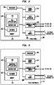
- FIGURE 2 illustrates details of one of the field panels 108 in accordance with the present disclosure.
- the field panel 108 comprises a processor 202, a memory 204, an input/output (I/O) module 206, a communication module 208, a user interface 210 and a power module 212.
- the memory 204 comprises any suitable data store capable of storing data, such as instructions 220 and a database 222. It will be understood that the field panel 108 may be implemented in any other suitable manner without departing from the scope of this disclosure.
- the processor 202 is configured to operate the field panel 108.
- the processor 202 may be coupled to the other components 204, 206, 208, 210 and 212 of the field panel 108.
- the processor 202 may be configured to execute program instructions or programming software or firmware stored in the instructions 220 of the memory 204, such as building automation system (BAS) application software 230.
- BAS building automation system
- the memory 204 may also store other data for use by the system 100 in the database 222, such as various records and configuration files, graphical views and/or other information.
- Execution of the BAS application 230 by the processor 202 may result in control signals being sent to any field devices 112 that may be coupled to the field panel 108 via the I/O module 206 of the field panel 108. Execution of the BAS application 230 may also result in the processor 202 receiving status signals and/or other data signals from field devices 112 coupled to the field panel 108 and storage of associated data in the memory 204.
- the BAS application 230 may be provided by the Site Controls Controller software commercially available from Siemens Industry, Inc. However, it will be understood that the BAS application 230 may comprise any other suitable BAS control software.
- the I/O module 206 may comprise one or more input/output circuits that are configured to communicate directly with field devices 112. Thus, for some embodiments, the I/O module 206 comprises analog input circuitry for receiving analog signals and analog output circuitry for providing analog signals.
- the communication module 208 is configured to provide communication with the site controller 102, other field panels 108 and other components on the BLN 122.
- the communication module 208 is also configured to provide communication to the field controllers 110, as well as other components on the FLN 124 that is associated with the field panel 108.
- the communication module 208 may comprise a first port that may be coupled to the BLN 122 and a second port that may be coupled to the FLN 124.
- Each of the ports may include an RS-485 standard port circuit or other suitable port circuitry.
- the field panel 108 may be capable of being accessed locally via the interactive user interface 210.
- a user may control the collection of data from field devices 112 through the user interface 210.
- the user interface 210 of the field panel 108 may include devices that display data and receive input data. These devices may be permanently affixed to the field panel 108 or portable and moveable.
- the user interface 210 may comprise an LCD-type screen or the like and a keypad.
- the user interface 210 may be configured to both alter and show information regarding the field panel 108, such as status information and/or other data pertaining to the operation of, function of and/or modifications to the field panel 108.
- the power module 212 may be configured to supply power to the components of the field panel 108.
- the power module 212 may operate on standard 120 volt AC electricity, other AC voltages or DC power supplied by a battery or batteries.
- FIGURE 3 illustrates details of one of the field controllers 110 in accordance with the present disclosure.
- the field controller 110 comprises a processor 302, a memory 304, an input/output (I/O) module 306, a communication module 308 and a power module 312.
- the field controller 110 may also comprise a user interface (not shown in FIGURE 3 ) that is configured to alter and/or show information regarding the field controller 110.
- the memory 304 comprises any suitable data store capable of storing data, such as instructions 320 and a database 322. It will be understood that the field controller 110 may be implemented in any other suitable manner without departing from the scope of this disclosure.
- the field controller 110 may be positioned in, or in close proximity to, a room of the building where temperature or another environmental parameter associated with the subsystem may be controlled with the field controller 110.
- the processor 302 is configured to operate the field controller 110.
- the processor 302 may be coupled to the other components 304, 306, 308 and 312 of the field controller 110.
- the processor 302 may be configured to execute program instructions or programming software or firmware stored in the instructions 320 of the memory 304, such as subsystem application software 330.
- the subsystem application 330 may comprise a temperature control application that is configured to control and process data from all components of a temperature control subsystem, such as a temperature sensor, a damper actuator, fans, and various other field devices.
- the memory 304 may also store other data for use by the subsystem in the database 322, such as various configuration files and/or other information.
- Execution of the subsystem application 330 by the processor 302 may result in control signals being sent to any field devices 112 that may be coupled to the field controller 110 via the I/O module 306 of the field controller 110. Execution of the subsystem application 330 may also result in the processor 302 receiving status signals and/or other data signals from field devices 112 coupled to the field controller 110 and storage of associated data in the memory 304.
- the I/O module 306 may comprise one or more input/output circuits that are configured to communicate directly with field devices 112.
- the I/O module 306 comprises analog input circuitry for receiving analog signals and analog output circuitry for providing analog signals.
- the communication module 308 is configured to provide communication with the field panel 108 corresponding to the field controller 110 and other components on the FLN 124, such as other field controllers 110.
- the communication module 308 may comprise a port that may be coupled to the FLN 124.
- the port may include an RS-485 standard port circuit or other suitable port circuitry.
- the power module 312 may be configured to supply power to the components of the field controller 110.
- the power module 312 may operate on standard 120 volt AC electricity, other AC voltages, or DC power supplied by a battery or batteries.
- the heating and cooling energy being supplied to a zone can be explicitly defined and quantified by heat transfer equations, but the amount of daylighting available from ECG adjustment is highly variable, depending on outside sun conditions, time of day, season of year, and glare considerations.
- Other objectives include blocking direct sunlight, thereby reducing glare and solar heat gains during the cooling season, allowing the maximum possible amount of daylight (and solar heat gain) during the heating season, controlling direct sunlight by diffusing it into the space without causing glare on sunny days, transmitting all available daylight on overcast days, and eliminating glare and creating a pleasant luminous environment.
- Glare can be very difficult to measure and extremely complicated to calculate analytically.
- the perception of glare by the occupants of a perimeter building space depends on their viewing directions (e.g. the orientation of their locations) with respect to the source of glare.
- glare from windows can be controlled by controlling the ECG tint level.
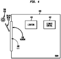
- FIGURE 4 illustrates a block diagram of a room 400 that can be managed using disclosed techniques.
- Room 400 includes climate control 402, which can include heating, cooling, and ventilation systems, all of which consume energy, and which can regulate the temperature and humidity of room 400.
- Room 400 also includes lighting 404, which consumes energy, and which can be varied in illumination depending on the natural light in the room.
- Room 400 has a window 406 with ECG 408.
- the sun 410 can illuminate room 400 through window 406, and the amount of illumination can be adjusted using ECG 408.
- Room 400 can lose heat or gain heat through window 406, depending on weather conditions, the sun 410, the ECG 408, and other factors.
- glare in room 400 can be a significant problem, but disclosed embodiments can adjust the tint level of ECG 408 to control glare.
- Glare control can be used to override the calculated optimum ECG tint level described below (to minimize total energy consumption) whenever solar beam radiation is detected during occupied hours.
- the climate control 402 is implemented as radiant heating and cooling ceiling panels.
- Disclosed embodiments can use an analytical process for managing energy consumption based on finding the room temperature response to solar radiation from various ECG tint levels, for any time of day or season of year. This can include solving two coupled first-order differential equations.
- a differential equation can be used to properly model the room temperature response to incoming solar radiation through ECG system since, in the real world, room temperature does not respond instantly to incoming solar radiation through ECG, but lags in time response due to the thermal capacitance of the room and heat flows into and out of the room.
- FIGURE 5 illustrates an example of a system model that can be analyzed in accordance with disclosed embodiments.
- This example illustrates a system with a radiant ceiling panel system used for terminal heating and cooling, but those of skill in the art will recognize that with only minor changes to the mathematics, this basic solution approach can be applied to a wide variety of terminal heating or cooling devices.
- FIGURE 5 illustrates a number of system elements that represent energy and heat transferred into and out of a room 502 having electrical lighting 504 and radiant ceiling panels 506.
- Fig. 5 also illustrates a window 508 with ECG 510. In this figure or as described herein,
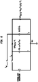
- FIGURE 6 illustrates an equivalent thermal network for lumped heat capacities of room air and outside walls with room thermal masses in corresponding to the system illustrated in Fig. 5 .
- R I represents the area transmittance between room air and walls and is equal to the thermal resistance R-value divided by the area of heat transfer surface
- R O represents the area transmittance between center of wall and ambient surroundings and is equal to the thermal resistance R-value divided by the area of heat transfer surface
- C air represents the thermal capacitance of the room air
- C W represents the thermal capacitance of the surrounding walls
- h iw represents the convection heat transfer coefficient at inner wall(s) surface
- a iw represents the area of inner wall(s) surface
- h ow represents the convection heat transfer coefficient at outside wall(s) surface
- a ow represents the area of outside wall(s) surface
- k ow represents the thermal conductivity of outside wall(s)
- ⁇ x ow represents the thickness of outside wall(s).
- FIGURE 7 illustrates a flowchart of a process in accordance with disclosed embodiments for integrated room management in a building management system. Such a process can be performed by a data processing system such as building automation system 100, and is referred to generically as the "system" below.
- the system can determine a solar heat gain coefficient (SHGC) for a room in a building, such as based on the geographic location of the room and orientation of the outside window(s), at a plurality of time intervals (702).
- the time intervals can be, for example every fifteen minutes during business hours of a given day, or can be other appropriate intervals on a time and date that the room is expected to be occupied.
- the SHGC may be given by the manufacturer as a function of the incoming solar radiation flux.
- the SHGC can be calculated using the equation: C air ⁇ T t ⁇ ⁇ t
- t i ⁇ q ⁇ g ⁇ q ⁇ elect light t i ⁇ i SHGC t i ⁇ i ⁇ UA pf T out ⁇ T
- t i R I E ti A pf cos ⁇ i cos ⁇ i where sin ⁇ i cosL ⁇ cos ⁇ ⁇ cos 15 t i + E 60 ⁇ LSM ⁇ LON 15 ⁇ 12 + sinL ⁇ sin ⁇
- a subscript i for a variable indicates that it represents that variable's value at the time interval i.
- the system determines predicted room temperatures for the room at the plurality of time intervals based on the SHGC and a plurality of ECG tint levels (704).
- T(t) ⁇ in ⁇ ⁇ in T in ⁇ T ⁇ V air
- q ⁇ g C air q ⁇ elect light t C air + UA pf T out ⁇ T + E ti A pf SHGC t i VLT C air + T w ⁇ T R I C air
- dT w dt
- the system can calculate the predicted room temperature for the each time interval for each ECG tint level.
- the system determines illumination heat and illumination energy for the room, at each ECG tint level and at each time interval, based on an exterior illumination level for each ECG tint level, artificial lighting energy consumed, and artificial lighting heat produced to bring the room to a predetermined illumination level (706).
- This step can include calculating the predicted workplane surface light illumination level for each projected ECG tint level, and the heat output of the lights at the corresponding dimming level.
- the artificial lighting energy consumed and artificial lighting heat produced to bring the room to the predetermined illumination level are measured for the installed lighting 404 based on the energy and heat produced by the lighting used to raise I room to the predetermined illumination level.
- the energy and heat required will be less when natural lighting I daylight is high, and higher when I daylight is low. These measurements need only be performed once, at various lighting/dimming levels, for the installed lighting 404 in any given room.
- the system determines room climate energy, at each of the time intervals, required to maintain the room at a predetermined temperature based on the predicted open-loop room temperatures and the illumination heat at each of the time intervals (708). For any given climate control 402, the system can determine energy required to heat or cool the room to the predetermined temperature from the predicted temperatures and the heat produced from the installed lighting 404 (in the amount needed for to ensure the illumination level as described above).
- the system determines a total room energy at each of the time intervals as a function of the ECG tint levels based on the climate energy, illumination energy, and predicted open-loop room temperatures (710).
- the system can add the energy required to heat or cool the room to the predetermined temperature, by climate control 402 from the predicted temperatures and for each ECG tint level, to the illumination energy required to ensure the predetermined illumination to get a projected total room energy curve as a function of the ECG tint levels.
- the system determines, from the total room energy, an optimal ECG tint level at each of the time intervals.
- the optimal ECG tint level is the level that minimizes the total room energy at each of the time intervals (712).
- the electrochromic glass manufacturer offers continuously variable tint levels for their ECG, this can be performed by taking the first derivative (or minimum) of this projected total room energy curve with respect to the ECG tint level, setting it equal to zero, and solving for the ECG tint level.
- This will be the optimal ECG tint level that minimizes the total room energy, while maintaining occupant comfort for illumination and temperature.
- the optimal ECG tint level provides external illumination to the room while preventing glare.
- the system can control the ECG tint levels in the room at each of the time intervals according to the optimal ECG tint level (714). Once the optimal ECG tint levels for each time interval are known, the system can adjust ECG 408 so that they are tinted at the optimal ECG tint level. This can be performed at all times, at each time interval, only when the room is occupied, or unless there is an override condition as described below.
- the system can enter an override condition in response to detecting beam solar radiation in the room, which can produce unpleasant glare, and in this override condition, control the ECG tint level in the room (716). Such a case may require additional lighting or room climate energy since some of the radiant energy from the sun will be blocked.
- the system can enter an override condition in response to a manual user-desired tint level of the ECG in the room, and in this override condition, controls the ECG tint levels according to the manual user control (718).
- Such a case may require additional or even less lighting or climate energy since the amount of radiant energy from the sun will be changed.
- the system can enter an override condition in response to a room condition (720). For example, the system can determine that the room is empty, so no lighting is required, that it is night, so there is no external lighting and the ECG tint level can be completely opaque, substantially transparent, or otherwise.
- machine usable/readable or computer usable/readable mediums include: nonvolatile, hard-coded type mediums such as read only memories (ROMs) or erasable, electrically programmable read only memories (EEPROMs), and user-recordable type mediums such as floppy disks, hard disk drives and compact disk read only memories (CD-ROMs) or digital versatile disks (DVDs).
- ROMs read only memories
- EEPROMs electrically programmable read only memories
- user-recordable type mediums such as floppy disks, hard disk drives and compact disk read only memories (CD-ROMs) or digital versatile disks (DVDs).
Landscapes
- Physics & Mathematics (AREA)
- Nonlinear Science (AREA)
- Engineering & Computer Science (AREA)
- General Physics & Mathematics (AREA)
- Optics & Photonics (AREA)
- General Engineering & Computer Science (AREA)
- Automation & Control Theory (AREA)
- Life Sciences & Earth Sciences (AREA)
- Thermal Sciences (AREA)
- Chemical & Material Sciences (AREA)
- Combustion & Propulsion (AREA)
- Mechanical Engineering (AREA)
- Sustainable Energy (AREA)
- Sustainable Development (AREA)
- Air Conditioning Control Device (AREA)
- Electrochromic Elements, Electrophoresis, Or Variable Reflection Or Absorption Elements (AREA)
- Circuit Arrangement For Electric Light Sources In General (AREA)
Description
- The present disclosure is directed, in general, to building-control systems, and in particular to control of automated lighting, heating, cooling, and electrochromic glass systems.
- Building automation systems encompass a wide variety of systems that aid in the monitoring and control of various aspects of building operation. Building automation systems include security systems, fire safety systems, lighting systems, and HVAC systems. The elements of a building automation system are widely dispersed throughout a facility. For example, an HVAC system may include temperature sensors and ventilation damper controls, as well as other elements, that are located in virtually every area of a facility. These building automation systems typically have one or more centralized control stations from which system data may be monitored and various aspects of system operation may be controlled and/or monitored.
- To allow for monitoring and control of the dispersed control system elements, building automation systems often employ multi-level communication networks to communicate operational and/or alarm information between operating elements, such as sensors and actuators, and the centralized control station. One example of a building automation system is the Site Controls Controller, available from Siemens Industry, Inc. Building Technologies Division of Buffalo Grove, Illinois. ("Siemens"). In this system, several control stations connected via an Ethernet, MSTP or another type of network may be distributed throughout one or more building locations, each having the ability to monitor and control system operation.
- Further, in the prior art, document D1 (
US 2013/0057937 ) describes an automated shade control in connection with electrochromic glass in which proactive and reactive control algorithms are used based on knowledge of how a building's occupants use window coverings and/or variable characteristics of a glass. The control algorithms include information about continuously varying solar angles established between the sun and the window opening over each day of the solar day. Further any inclination or declination angles of the window opening (i.e., window, sloped window, and/or skylight), any scheduled positioning of the window covering throughout the day/year, information about the British Thermal Unit (BTU) load impacting the window at anytime throughout the day/year; the glass characteristics which affect transmission of light and heat through the glass, and/or any other historical knowledge about performance of the window covering in that position from previous days/years may be included in the proactive control algorithms. D1 also describes proactive and/or reactive control algorithms in order to generate estimated and/or measured foot-candles on the glazing, foot-candles inside the glass and the like. - Document D2 (
US 2014/06 77 33 A1 ) describes an expert system which includes a model of the thermal performance of a building in response to various equipment loads. The expert system is implemented as a learning system to develop and improve prediction and forecasting. D2 also describes an electrochromic window which is controlled in response to a command change. Furthermore, an information system collects and transmits measured/calculated data. The transmission of the measured/calculated data in real-time enables "superior energy management". - Document D3 (
US 2013/190940 A1 ) describes the controlling of a building based on one or more temperature set points received by a thermostat. - The object of the present invention is to provide methods for integrated room management in a building management system and corresponding systems and computer-readable mediums. This object is solved by a method of claim 1 and by a building management system of claim 6 and a non-transitory computer readable medium of claim 12. Further advantageous embodiments and improvements of the invention are listed in the dependent claims. Hereinafter, aspects of the invention which contribute to the understanding of the invention are discussed before coming to a detailed description of the embodiments of the invention with reference to the attached drawings. However, it should be noted that the invention is defined by the attached claims and embodiments not covered by the scope of the claims are also to be understood as examples and aspects contributing to the understanding of the invention. According to one aspect, a method includes determining a solar heat gain coefficient (SHGC) for a room in a building, based on the geographic location of the room and orientation of the exterior window(s), at a plurality of time intervals. The method includes determining predicted open-loop room temperatures ("open-loop" means with the terminal cooling or heating equipment turned off) for the room at the plurality of time intervals based on the SHGC and a plurality of window glass tint levels. The method includes determining illumination in the room and the thermal energy of the terminal heating or cooling equipment required to condition the room, at each window glass tint level and at each time interval, based on the measured exterior illumination level of the sun for each window glass tint level, measured artificial lighting energy consumed, and measured artificial lighting heat produced to bring the room to a predetermined illumination level. The method includes determining room climate energy, at each of the time intervals, required to maintain the room at a predetermined temperature based on the predicted open-loop room temperature response and the calculated thermal energy of the terminal heating or cooling equipment and illumination heat at each of the time intervals. The method includes adding the calculated thermal energy of the terminal heating or cooling equipment to the electrical lighting thermal energy to determine a total room energy at each of the time intervals as a function of the window glass tint levels based on the room climate energy and illumination energy required to condition and illuminate the room. The method includes determining, from the total room energy, an optimal glass tint level at each of the time intervals, wherein the optimal glass tint level minimizes the total room energy at each of the time intervals. The method includes controlling the glass tint levels in the room at each of the time intervals according to the optimal glass tint levels, unless there is an override condition. The system can enter an override condition in response to detecting beam solar radiation in the room. The system can enter an override condition in response to a manual user control of the electrochromic glass (ECG) tint level, and thereafter controls the glass tint levels according to the manually set tint level.
- Another method includes determining a solar heat gain coefficient (SHGC) for a room in a building at a plurality of time intervals. The method includes determining predicted open-loop room temperatures for the room at the plurality of time intervals based on the SHGC and a plurality of electrochromic glass (ECG) tint levels. The method includes determining illumination heat and illumination energy for the room, at each ECG tint level and at each time interval, based on a measured solar illumination level for each ECG tint level, artificial lighting energy consumed, and artificial lighting heat produced to bring the room to a predetermined illumination level. The method includes determining climate energy, at each of the time intervals, required to maintain the room at a predetermined temperature based on the predicted open-loop room temperatures and the illumination heat at each of the time intervals. The method includes determining a total room energy at each of the time intervals as a function of the ECG tint levels based on the climate energy, illumination energy, and predicted room temperatures. The method includes determining, from the total room energy, an optimal ECG tint level at each of the time intervals, wherein the optimal ECG tint level minimizes the total room energy at each of the time intervals. The method includes controlling the ECG tint levels in the room at each of the time intervals according to the optimal ECG tint level, unless there is an override condition.
- The foregoing has outlined rather broadly the features and technical advantages of the present disclosure so that those skilled in the art may better understand the detailed description that follows. Additional features and advantages of the disclosure will be described hereinafter that form the subject of the claims. Those skilled in the art will appreciate that they may readily use the conception and the specific embodiment disclosed as a basis for modifying or designing other structures without departing from the protection scope of the appended claims according to Art. 69 of the EPC protocol.
- Before undertaking the DETAILED DESCRIPTION below, it may be advantageous to set forth definitions of certain words or phrases used throughout this patent document: the terms "include" and "comprise," as well as derivatives thereof, mean inclusion without limitation; the term "or" is inclusive, meaning and/or; the phrases "associated with" and "associated therewith," as well as derivatives thereof, may mean to include, be included within, interconnect with, contain, be contained within, connect to or with, couple to or with, be communicable with, cooperate with, interleave, juxtapose, be proximate to, be bound to or with, have, have a property of, or the like; and the term "controller" means any device, system or part thereof that controls at least one operation, whether such a device is implemented in hardware, firmware, software or some combination of at least two of the same. It should be noted that the functionality associated with any particular controller may be centralized or distributed, whether locally or remotely. Definitions for certain words and phrases are provided throughout this patent document, and those of ordinary skill in the art will understand that such definitions apply in many, if not most, instances to prior as well as future uses of such defined words and phrases. While some terms may include a wide variety of embodiments, the appended claims may expressly limit these terms to specific embodiments. Furthermore, in the present disclosure, for the description of the embodiments of the invention, often non-SI-units like BTU, hr, ft, lb, °F, °R are used in the following equations. These units can, however, easily be converted into the corresponding SI units: BTU = 1055 joules, hr = hours, ft = 0.3048 meter, lb = 1/2.2046226218488 kg, °F = °C∗1.8)+32 and °R=°F+459.67 . The unit footcandle is converted to the SI unit Lux as follows: 1 Lux = 0.0929030400000839 footcandle.
- For a more complete understanding of the present disclosure, and the advantages thereof, reference is now made to the following descriptions taken in conjunction with the accompanying drawings, wherein like numbers designate like objects, and in which:
-
FIGURE 1 illustrates a block diagram of a building automation system in which the energy efficiency of a heating, ventilation, and air conditioning (HVAC) system may be improved in accordance with the present disclosure; -
FIGURE 2 illustrates details of one of the field panels ofFIGURE 1 in accordance with the present disclosure; -
FIGURE 3 illustrates details of one of the field controllers ofFIGURE 1 in accordance with the present disclosure; -
FIGURE 4 illustrates a block diagram of a room that can be managed using disclosed techniques; -
FIGURE 5 illustrates an example of a system model that can be analyzed in accordance with disclosed embodiments; -
FIGURE 6 illustrates an equivalent thermal network for lumped heat capacities and thermal resistances of room air and outside walls with room thermal masses in corresponding to the system illustrated inFig. 5 ; and -
FIGURE 7 illustrates a flowchart of a process in accordance with disclosed embodiments. -
FIGURES 1 through 7 , discussed below, and the various embodiments used to describe the principles of the present disclosure in this patent document are by way of illustration only and should not be construed in any way to limit the scope of the disclosure. Those skilled in the art will understand that the principles of the present disclosure may be implemented in any suitably arranged device. The numerous innovative teachings of the present application will be described with reference to exemplary non-limiting embodiments. - Disclosed embodiments include systems and methods for optimization of room control for the perimeter building zones that have facades with windows with ECG. "Optimization" control refers to minimization of energy and maintenance of acceptable lighting and thermal comfort conditions for room occupants. Occupant comfort in a building environment includes both thermal comfort (temperature and relative humidity in the right range) and good lighting conditions (which includes absence or minimization of glare). Daylighting, the control of illumination from daylight, will be adjusted by means of controlling the ECG tint level. One non-limiting example of an ECG that can be used in some implementations is the SageGlass electrochromic glass manufactured by SAGE Electrochromics, Inc.
- Disclosed embodiments can be used with many different building types, and are particularly advantageous for use in office buildings since office buildings generally require a given illumination level (e.g. in footcandles or lux) on workplane surfaces to provide adequate lighting for its workers.
- Specific terms that may be used herein are described below. A candela (cd)is a measure of intensity of light source in a given direction. A clo is a unit used to express the thermal insulation provided by garments and clothing ensembles, where 1 clo = 0.155 m2∗°C/W (=0.88 ft2∗hr∗°F/Btu). Energy (heat) flux refers to energy flow per unit area (BTU/hr-ft2). Fenestration is an architectural term that refers to the arrangement, proportion, and design of window, skylight, and door systems in a building. Fenestration can serve as a physical and/or visual connection to the outdoors, as well as a means to admit solar radiation for daylighting, and for heat gain to a space.
- Footcandles (fc) indicates the density of light landing on a surface, and is generally measured in lumens per sq.ft. Glare refers to luminances within the field of vision that are too great for the eye to adapt to. The indoor solar attenuation coefficient (IAC) represents the fraction of heat flow that enters the room, some energy having been excluded by the shading. Depending on the type of shade, it may vary angularly and with shade type and geometry. Illuminance is a measure of light incident on a surface, generally measured in lumens per sq.ft. Luminance measures the brightness of a surface when viewed from a particular direction and is generally expressed in candelas per square meter. Lumen (lm) refers to the total amount of light emanating from a light source. Lux refers to the International System of Units (SI) unit of light density equivalent to footcandles (the English unit), where 1 lux = 1 lumen per square meter.
- The use of daylighting in building designs is increasingly being recognized as a primary way to not only reduce electrical lighting energy consumption in buildings but to enhance indoor environmental quality (IEQ) for the people (workers) present in the building. When designing for maximum daylight, designers must evaluate and balance a number of environmental factors, such as heat gain and loss, glare control, visual quality, and variations in daylight availability. Daylighting can enhance IEQ in several ways: by providing a natural view to the outdoors, providing natural daylight to work surfaces, and reducing glare from electrical lighting. Studies have shown that when IEQ is enhanced, worker productivity increases, student test scores increase, and absenteeism is reduced.
- Offices with sufficient natural daylight and a visual connection to the outdoors have been proven to increase occupant productivity and comfort, leading to better employee retention and reduced absenteeism. Successful daylighting designs can use diffuse light from the sky through both skylights and window facades, and use daylighting as the primary source of illumination inside a building. Successful daylighting designs when the daylighting controls are integrated with the electric lighting system provide not only electrical lighting energy savings, but a quality visual environment, with worker productivity increases and reduced absenteeism.
- Daylighting reduces the need for electrical lighting of building interiors, which, if integrated into the overall approach to lighting, can result in a significant decrease in electrical lighting requirements. A well-designed daylit building is estimated to reduce lighting energy use by 50% to 80%. According to the U.S. Department of Energy, the energy used in U.S. office buildings consumed by HVAC systems accounts for 51% of the total energy required and 25% of the lighting energy required. Therefore, a primary target for reducing energy consumption in office buildings is to minimize HVAC and lighting energy.
- Electrochromic glass (ECG) is glass or glazing whose light transmission properties are altered when voltage is applied across the thickness of the glass. Generally, the opacity of the glass changes from translucent to transparent, changing from blocking some (or all) wavelengths of light to letting light pass through. ECG can be used to control daylight into a perimeter space by light transmission through the window glass. In general, maximizing daylighting will minimize the need for electric lighting, and while the maximizing of daylighting will reduce heating loads in winter (the heating season), the solar heat gain through windows will also increase cooling loads in summer (the cooling season). In addition, in an office environment, direct daylighting into a space can also cause glare, and minimization of glare must be included along with thermal comfort as the top priority to provide a comfortable environment for employees. Therefore, one objective is to provide maximum daylighting for the dynamic shading systems while minimizing glare, and then once glare has been minimized (such as on a cloudy day, or when the sun is not directly striking the window surfaces) to maximize daylighting, up to the point where the cooling load from the added solar heat gain becomes excessive.
- The general control objectives of the dynamic shading systems can be summed up as balancing the need to block direct sunlight, thereby reducing glare and solar heat gains during the cooling season, the need to allow the maximum possible amount of daylight (and solar heat gain) during the heating season, the need to control direct sunlight by diffusing it into the space without causing glare on sunny days, the need to transmit all available daylight on overcast days, and in general the need to eliminate glare and create a pleasant luminous environment.
- Current building management systems cannot integrate lighting and daylighting controls with HVAC controls to minimize total energy consumption while maintaining occupant comfort. Perimeter zones gain heat and light by the influx of solar radiation through the windows, which must be removed by cooling (or less heating) energy supplied to the space. Cooling and heating the space can be supplied by a variety of methods, depending on the type of HVAC supply air distribution system and terminal heating/cooling equipment.
- In general, maximizing daylighting in a perimeter zone during the cooling season will minimize the need for electric lighting, but may increase cooling loads in the zone to maintain the required space temperature conditions, and may cause glare. Similarly, maximizing daylighting in a perimeter zone during the heating season will minimize the need for electric lighting and reduce heating loads, but may cause occupant discomfort from direct sunlight penetrating deep into the space due to the relatively low position of the sun in wintertime as it arches across the sky.
- Perimeter zones gain heat and light by the influx of solar radiation through the windows, which must be removed by cooling (or less heating) energy supplied to the space. Cooling and heating the space can be supplied by a variety of methods, depending on the type of HVAC supply air distribution system and terminal heating/cooling equipment.
- In general, maximizing daylighting in a perimeter zone during the cooling season will minimize the need for electric lighting, but may increase cooling loads in the zone to maintain the required space temperature conditions, and may cause glare. Similarly, maximizing daylighting in a perimeter zone during the heating season will minimize the need for electric lighting and reduce heating loads, but may cause occupant discomfort from direct sunlight penetrating deep into the space due to the relatively low position of the sun in wintertime as it arches across the sky. Therefore, there are both energy and comfort trade-offs that should be made in the development of the system model.
- When the ECG transmits or passes all or substantially all of the exterior lighting, minimal electrical lighting energy is needed but maximum cooling from the radiant cooling panels may be needed to meet required space temperature conditions. Likewise, when the ECG blocks all or substantially all of the exterior lighting, minimal radiant cooling is needed to meet space temperature conditions, but maximum electrical lighting may be needed to make up for the loss of daylighting by the high tint level of the ECG. In general, an optimal ECG glass tint level exists where total energy consumption is minimized.
- However, the general problem of optimizing the ECG tint level to minimize energy consumption for a zone can be complex. The amount of daylighting available is highly variable, and depends not only on outside sun conditions, passing clouds, time of day, and season of year, but also on the design of the ECG itself. In addition, the "optimal" ECG tint level that may result in minimal total energy consumption may also produce glare conditions within the space and should not be chosen as the optimal tint level for the occupants of the space. Therefore, disclosed embodiments include an advanced analytical approach that can determine the overall ECG tint level that will minimize energy, with the constraint of minimizing glare. The invention is defined by the appended claims. Therefore, hereinafter, the embodiments and/or clauses and/or examples of the description which are not covered by the appended claims are considered as not being part of the present invention and merely serve further explanations contributing to the understanding of the invention.
-
FIGURE 1 illustrates a block diagram of abuilding automation system 100 in which disclosed embodiments can be implemented. Thebuilding automation system 100 is an environmental control system configured to control at least one of a plurality of environmental parameters within a building, such as temperature, humidity, lighting and/or the like. For example, for a particular embodiment, thebuilding automation system 100 may comprise the Site Controls Controller building automation system that allows the setting and/or changing of various controls of the system. While a brief description of thebuilding automation system 100 is provided below, it will be understood that thebuilding automation system 100 described herein is only one example of a particular form or configuration for a building automation system and that thesystem 100 may be implemented in any other suitable manner without departing from the scope of this disclosure. - For the illustrated embodiment, the
building automation system 100 comprises asite controller 102, areport server 104, a plurality ofclient stations 106a-c, a plurality offield panels 108a-b, a plurality offield controllers 110a-e and a plurality offield devices 112a-d. Although illustrated with three client stations 106, twofield panels 108, fivefield controllers 110 and fourfield devices 112, it will be understood that thesystem 100 may comprise any suitable number of any of thesecomponents - The
site controller 102, which may comprise a computer or a general-purpose processor, is configured to provide overall control and monitoring of thebuilding automation system 100. Thesite controller 102 may operate as a data server that is capable of exchanging data with various elements of thesystem 100. As such, thesite controller 102 may allow access to system data by various applications that may be executed on thesite controller 102 or other supervisory computers (not shown inFIGURE 1 ). - For example, the
site controller 102 may be capable of communicating with other supervisory computers, Internet gateways, or other gateways to other external devices, as well as to additional network managers (which in turn may connect to more subsystems via additional low-level data networks) by way of a management level network (MLN) 120. Thesite controller 102 may use theMLN 120 to exchange system data with other elements on theMLN 120, such as thereport server 104 and one or more client stations 106. Thereport server 104 may be configured to generate reports regarding various aspects of thesystem 100. Each client station 106 may be configured to communicate with thesystem 100 to receive information from and/or provide modifications to thesystem 100 in any suitable manner. TheMLN 120 may comprise an Ethernet or similar wired network and may employ TCP/IP, BACnet, and/or other protocols that support high-speed data communications. - The
site controller 102 may also be configured to accept modifications and/or other input from a user. This may be accomplished via a user interface of thesite controller 102 or any other user interface that may be configured to communicate with thesite controller 102 through any suitable network or connection. The user interface may include a keyboard, touchscreen, mouse, or other interface components. Thesite controller 102 is configured to, among other things, affect or change operational data of thefield panels 108, as well as other components of thesystem 100. Thesite controller 102 may use a building level network (BLN) 122 to exchange system data with other elements on theBLN 122, such as thefield panels 108. - Each
field panel 108 may comprise a general-purpose processor and is configured to use the data and/or instructions from thesite controller 102 to provide control of its one or morecorresponding field controllers 110. While thesite controller 102 is generally used to make modifications to one or more of the various components of thebuilding automation system 100, afield panel 108 may also be able to provide certain modifications to one or more parameters of thesystem 100. Eachfield panel 108 may use a field level network (FLN) 124 to exchange system data with other elements on theFLN 124, such as a subset of thefield controllers 110 coupled to thefield panel 108. - Each
field controller 110 may comprise a general-purpose processor and may correspond to one of a plurality of localized, standard building automation subsystems, such as building space temperature control subsystems, lighting control subsystems, or the like. For a particular embodiment, thefield controllers 110 may comprise the model TEC (Terminal Equipment Controller) available from Siemens. However, it will be understood that thefield controllers 110 may comprise any other suitable type of controllers without departing from the scope of the present invention. - To carry out control of its corresponding subsystem, each
field controller 110 may be coupled to one ormore field devices 112. Eachfield controller 110 is configured to use the data and/or instructions from itscorresponding field panel 108 to provide control of its one or morecorresponding field devices 112. For some embodiments, some of thefield controllers 110 may control their subsystems based on sensed conditions and desired set point conditions. For these embodiments, thesefield controllers 110 may be configured to control the operation of one ormore field devices 112 to attempt to bring the sensed condition to the desired set point condition. It is noted that in thesystem 100, information from thefield devices 112 may be shared between thefield controllers 110, thefield panels 108, thesite controller 102 and/or any other elements on or connected to thesystem 100. In specific embodiments described herein,field devices 112 can include ECG controllers that control ECG tint levels (the opacity of the glass and how much light is passed through the glass), temperature sensors, lighting/illumination controls or sensors, beam detectors that detect direct sunlight, and others. In some embodiments, the thermal environment of a room can be measured by dry bulb temperature and relative humidity sensors that functions thefield devices 112. - In order to facilitate the sharing of information between subsystems, groups of subsystems may be organized into an
FLN 124. For example, the subsystems corresponding to thefield controllers field panel 108a to form theFLN 124a. TheFLNs 124 may each comprise a low-level data network that may employ any suitable proprietary or open protocol. - Each
field device 112 may be configured to measure, monitor and/or control various parameters of thebuilding automation system 100. Examples offield devices 112 include lights, thermostats, temperature sensors, fans, damper actuators, heaters, chillers, alarms, HVAC devices, and numerous other types of field devices. Thefield devices 112 may be capable of receiving control signals from and/or sending signals to thefield controllers 110, thefield panels 108 and/or thesite controller 102 of thebuilding automation system 100. Accordingly, thebuilding automation system 100 is able to control various aspects of building operation by controlling and monitoring thefield devices 112. - As illustrated in
FIGURE 1 , any of thefield panels 108, such as thefield panel 108a, may be directly coupled to one ormore field devices 112, such as thefield devices field panel 108a may be configured to provide direct control of thefield devices field controllers field controller 110 for one or more particular subsystems may be provided by afield panel 108 without the need for afield controller 110. -
FIGURE 2 illustrates details of one of thefield panels 108 in accordance with the present disclosure. For this particular embodiment, thefield panel 108 comprises aprocessor 202, amemory 204, an input/output (I/O)module 206, acommunication module 208, auser interface 210 and apower module 212. Thememory 204 comprises any suitable data store capable of storing data, such asinstructions 220 and adatabase 222. It will be understood that thefield panel 108 may be implemented in any other suitable manner without departing from the scope of this disclosure. - The
processor 202 is configured to operate thefield panel 108. Thus, theprocessor 202 may be coupled to theother components field panel 108. Theprocessor 202 may be configured to execute program instructions or programming software or firmware stored in theinstructions 220 of thememory 204, such as building automation system (BAS)application software 230. In addition to storing theinstructions 220, thememory 204 may also store other data for use by thesystem 100 in thedatabase 222, such as various records and configuration files, graphical views and/or other information. - Execution of the
BAS application 230 by theprocessor 202 may result in control signals being sent to anyfield devices 112 that may be coupled to thefield panel 108 via the I/O module 206 of thefield panel 108. Execution of theBAS application 230 may also result in theprocessor 202 receiving status signals and/or other data signals fromfield devices 112 coupled to thefield panel 108 and storage of associated data in thememory 204. In one embodiment, theBAS application 230 may be provided by the Site Controls Controller software commercially available from Siemens Industry, Inc. However, it will be understood that theBAS application 230 may comprise any other suitable BAS control software. - The I/
O module 206 may comprise one or more input/output circuits that are configured to communicate directly withfield devices 112. Thus, for some embodiments, the I/O module 206 comprises analog input circuitry for receiving analog signals and analog output circuitry for providing analog signals. - The
communication module 208 is configured to provide communication with thesite controller 102,other field panels 108 and other components on theBLN 122. Thecommunication module 208 is also configured to provide communication to thefield controllers 110, as well as other components on theFLN 124 that is associated with thefield panel 108. Thus, thecommunication module 208 may comprise a first port that may be coupled to theBLN 122 and a second port that may be coupled to theFLN 124. Each of the ports may include an RS-485 standard port circuit or other suitable port circuitry. - The
field panel 108 may be capable of being accessed locally via theinteractive user interface 210. A user may control the collection of data fromfield devices 112 through theuser interface 210. Theuser interface 210 of thefield panel 108 may include devices that display data and receive input data. These devices may be permanently affixed to thefield panel 108 or portable and moveable. For some embodiments, theuser interface 210 may comprise an LCD-type screen or the like and a keypad. Theuser interface 210 may be configured to both alter and show information regarding thefield panel 108, such as status information and/or other data pertaining to the operation of, function of and/or modifications to thefield panel 108. - The
power module 212 may be configured to supply power to the components of thefield panel 108. Thepower module 212 may operate on standard 120 volt AC electricity, other AC voltages or DC power supplied by a battery or batteries. -
FIGURE 3 illustrates details of one of thefield controllers 110 in accordance with the present disclosure. For this particular embodiment, thefield controller 110 comprises aprocessor 302, amemory 304, an input/output (I/O)module 306, acommunication module 308 and apower module 312. For some embodiments, thefield controller 110 may also comprise a user interface (not shown inFIGURE 3 ) that is configured to alter and/or show information regarding thefield controller 110. Thememory 304 comprises any suitable data store capable of storing data, such asinstructions 320 and adatabase 322. It will be understood that thefield controller 110 may be implemented in any other suitable manner without departing from the scope of this disclosure. For some embodiments, thefield controller 110 may be positioned in, or in close proximity to, a room of the building where temperature or another environmental parameter associated with the subsystem may be controlled with thefield controller 110. - The
processor 302 is configured to operate thefield controller 110. Thus, theprocessor 302 may be coupled to theother components field controller 110. Theprocessor 302 may be configured to execute program instructions or programming software or firmware stored in theinstructions 320 of thememory 304, such assubsystem application software 330. For a particular example, thesubsystem application 330 may comprise a temperature control application that is configured to control and process data from all components of a temperature control subsystem, such as a temperature sensor, a damper actuator, fans, and various other field devices. In addition to storing theinstructions 320, thememory 304 may also store other data for use by the subsystem in thedatabase 322, such as various configuration files and/or other information. - Execution of the
subsystem application 330 by theprocessor 302 may result in control signals being sent to anyfield devices 112 that may be coupled to thefield controller 110 via the I/O module 306 of thefield controller 110. Execution of thesubsystem application 330 may also result in theprocessor 302 receiving status signals and/or other data signals fromfield devices 112 coupled to thefield controller 110 and storage of associated data in thememory 304. - The I/
O module 306 may comprise one or more input/output circuits that are configured to communicate directly withfield devices 112. Thus, for some embodiments, the I/O module 306 comprises analog input circuitry for receiving analog signals and analog output circuitry for providing analog signals. - The
communication module 308 is configured to provide communication with thefield panel 108 corresponding to thefield controller 110 and other components on theFLN 124, such asother field controllers 110. Thus, thecommunication module 308 may comprise a port that may be coupled to theFLN 124. The port may include an RS-485 standard port circuit or other suitable port circuitry. - The
power module 312 may be configured to supply power to the components of thefield controller 110. Thepower module 312 may operate on standard 120 volt AC electricity, other AC voltages, or DC power supplied by a battery or batteries. - The heating and cooling energy being supplied to a zone can be explicitly defined and quantified by heat transfer equations, but the amount of daylighting available from ECG adjustment is highly variable, depending on outside sun conditions, time of day, season of year, and glare considerations. Other objectives include blocking direct sunlight, thereby reducing glare and solar heat gains during the cooling season, allowing the maximum possible amount of daylight (and solar heat gain) during the heating season, controlling direct sunlight by diffusing it into the space without causing glare on sunny days, transmitting all available daylight on overcast days, and eliminating glare and creating a pleasant luminous environment.
- Glare can be very difficult to measure and extremely complicated to calculate analytically. In addition, the perception of glare by the occupants of a perimeter building space depends on their viewing directions (e.g. the orientation of their locations) with respect to the source of glare. However, glare from windows can be controlled by controlling the ECG tint level.
-
FIGURE 4 illustrates a block diagram of aroom 400 that can be managed using disclosed techniques.Room 400 includesclimate control 402, which can include heating, cooling, and ventilation systems, all of which consume energy, and which can regulate the temperature and humidity ofroom 400.Room 400 also includeslighting 404, which consumes energy, and which can be varied in illumination depending on the natural light in the room.Room 400 has awindow 406 withECG 408. Thesun 410 can illuminateroom 400 throughwindow 406, and the amount of illumination can be adjusted usingECG 408.Room 400 can lose heat or gain heat throughwindow 406, depending on weather conditions, thesun 410, theECG 408, and other factors. When thesun 410 has a solar beam 412 (direct sunlight) intowindow 406, glare inroom 400 can be a significant problem, but disclosed embodiments can adjust the tint level ofECG 408 to control glare. Glare control can be used to override the calculated optimum ECG tint level described below (to minimize total energy consumption) whenever solar beam radiation is detected during occupied hours. In the specific example of the process below, theclimate control 402 is implemented as radiant heating and cooling ceiling panels. - Disclosed embodiments can use an analytical process for managing energy consumption based on finding the room temperature response to solar radiation from various ECG tint levels, for any time of day or season of year. This can include solving two coupled first-order differential equations. A differential equation can be used to properly model the room temperature response to incoming solar radiation through ECG system since, in the real world, room temperature does not respond instantly to incoming solar radiation through ECG, but lags in time response due to the thermal capacitance of the room and heat flows into and out of the room.
-
FIGURE 5 illustrates an example of a system model that can be analyzed in accordance with disclosed embodiments. This example illustrates a system with a radiant ceiling panel system used for terminal heating and cooling, but those of skill in the art will recognize that with only minor changes to the mathematics, this basic solution approach can be applied to a wide variety of terminal heating or cooling devices. -
FIGURE 5 illustrates a number of system elements that represent energy and heat transferred into and out of aroom 502 havingelectrical lighting 504 andradiant ceiling panels 506.Fig. 5 also illustrates awindow 508 withECG 510. In this figure or as described herein, - Pin = supply duct air pressure;
- Padj = air pressure in adjacent space (or outside air pressure);
- Tin = supply air temperature;
- T = room air temperature;
- Tw = weighted average wall temperature;
- ṁin = supply air mass flow rate;
- ṁout = exhaust air mass flow rate;
- ṁexf = exfiltration air mass flow rate;
- hin = supply air enthalpy;
- P = room air pressure (absolute);
- T = room (dry bulb) air temperature (absolute);
- Tout = air (dry bulb) temperature in adjacent space (or outside air dry bulb temperature);
- m = mass of air in room;
- h = enthalpy of air in room;
- ρ = density of air in room;
- ρin = density of supply air to room;
- q̇t win = energy flux transmission of solar heat through windows;
- q̇elect lighting = thermal heat energy into the space from electric lighting;
- q̇g = internal heat generation from people and equipment in room;
- q̇r = radiant heat transfer from radiant ceiling panels;
- q̇c = convective heat transfer from radiant ceiling panels
- hiw = convection coefficient of inner wall surface of room
- how = convection coefficient of outer wall surface of room
- Aiw = area of inner wall surface of room
- Aow = area of outer wall surface of room
- Δxow = outside wall thickness
- kow = thermal conductivity of outside wall
- Note that sign convention used in this figure for energy inflow into the zone is positive, and for energy outflow it is negative. The radiative and convective heat transfer is shown leaving the zone, which represents a typical cooling application.
-
FIGURE 6 illustrates an equivalent thermal network for lumped heat capacities of room air and outside walls with room thermal masses in corresponding to the system illustrated inFig. 5 . In this figure, RI represents the area transmittance between room air and walls and is equal to the thermal resistance R-value divided by the area of heat transfer surface; RO represents the area transmittance between center of wall and ambient surroundings and is equal to the thermal resistance R-value divided by the area of heat transfer surface; Cair represents the thermal capacitance of the room air; CW represents the thermal capacitance of the surrounding walls; hiw represents the convection heat transfer coefficient at inner wall(s) surface; Aiw represents the area of inner wall(s) surface; how represents the convection heat transfer coefficient at outside wall(s) surface; Aow represents the area of outside wall(s) surface; kow represents the thermal conductivity of outside wall(s); and Δxow represents the thickness of outside wall(s). -
FIGURE 7 illustrates a flowchart of a process in accordance with disclosed embodiments for integrated room management in a building management system. Such a process can be performed by a data processing system such asbuilding automation system 100, and is referred to generically as the "system" below. - The system can determine a solar heat gain coefficient (SHGC) for a room in a building, such as based on the geographic location of the room and orientation of the outside window(s), at a plurality of time intervals (702). The time intervals can be, for example every fifteen minutes during business hours of a given day, or can be other appropriate intervals on a time and date that the room is expected to be occupied. In other cases, the SHGC may be given by the manufacturer as a function of the incoming solar radiation flux.
- The SHGC can be calculated using the equation:


- q̇elect lighting is the instantaneous lighting thermal energy output generated by the lights in units of


- Cair is the thermal capacitance of the room air;
- L = Local latitude;
- δ = solar declination angle;

- Eti = Equation of time in decimal minutes = 9.87sin(2B) - 7.53cosB - 1.5sinB, where

- LSM = Local Standard Meridian. Standard meridians are found every 15° from 0° at Greenwich, U.K. In the United States and Canada, these values are (i.e. the values of LSM in the above equation):
- o Atlantic Standard Time Meridian: 60°W
- o Eastern Standard Time Meridian: 75°W
- o Central Standard Time Meridian: 90°W
- o Mountain Standard Time Meridian: 105°W
- o Pacific Standard Time Meridian: 120°W
- o Alaska Standard Time Meridian: 135°W
- o Hawaii Standard Time Meridian: 150°W
- LON = Local longitude;
- t = local standard time in decimal hours;
- cosy = cos (ϕ - ψ) = cos ϕ · cos ψ + simϕ · sinψ, where ψ is a fixed value, depending on the surface azimuth angle orientation of the window;
- β = solar altitude angle above the horizontal;
- γ = surface solar azimuth angle;
- φ = solar azimuth angle. The solar azimuth angle is ZERO at solar noon and at solar midnight and increases positively in the counterclockwise direction for morning hours and increases positively in the clockwise direction for afternoon hours.
- Ψ = surface azimuth angle. Surfaces that face west have a positive surface azimuth ψ, while those facing east have a negative surface azimuth ψ.
- Eti = solar irradiance measurement;
- i = the specific time interval;
- Aroom = floor area of the room (ft2).
- ARCP= area of the radiant ceiling panels (ft2).
- q̇t Win = heat transmission flux through the windows in units of

- Tin = measured indoor air temperature, °F;
- Tout = measured outdoor air temperature, °F;
- Tw = weighted average wall temperature, °F;
- Apf = total projected area of fenestration (approximately the window's opening in the wall less installation clearances), ft2;
- U = overall heat transfer coefficient of the window,

- q̇ r = radiation heat flux in units of

- q̇c = heat flux from natural convection in

- T = measured indoor space dry-bulb air temperature, °F;
- P = absolute room air pressure

- R = Gas constant for air

- V = volume of the room (ft3);
- v̇ = the volumetric flow rate of air in, out, or exfiltrating (exf) from the room;
- cv = constant pressure;
- v̇in = supply airflow rate into the room
- cp,a = specific heat of dry air

-


-


- q̇g = internal heat generation from people and equipment in room;
- In general, a subscript i for a variable indicates that it represents that variable's value at the time interval i.
- The system determines predicted room temperatures for the room at the plurality of time intervals based on the SHGC and a plurality of ECG tint levels (704).
- To determine the predicted room temperatures, the system determines the open-loop room temperature response at each time interval to get the predicted room temperature as a function of time, T(t). This can be calculated using:


-

-

- Cw = ρwcwVw is the thermal capacitance of the outside wall using variables as described herein, and where
- βi = solar altitude angle above the horizontal at time interval t=ti;
- SHGC(ti (VLT)) is the solar heat gain coefficient at time interval t=ti, which depends on the visible light transmittance (VLT). The value of SHGC(ti (VLT)) can be calculated by the functional relationship between the VLT and SHGC as shown in below for an exemplary implementation;
- Eti is the measured total solar irradiance (beam + diffuse) at time interval t=ti (a constant).
- Using this equation, the system can calculate the predicted room temperature for the each time interval for each ECG tint level.
- The system determines illumination heat and illumination energy for the room, at each ECG tint level and at each time interval, based on an exterior illumination level for each ECG tint level, artificial lighting energy consumed, and artificial lighting heat produced to bring the room to a predetermined illumination level (706).
- To do so, the system can determine the value of k from direct measurements of Eti and Iroom using:

- Iroom = indoor illumination level (fc);
- Idaylight = indoor illumination level from daylighting (fc);
- k = constant of proportionality relating the measured indoor illumination level (fc) to the measured solar irradiance flux for the given projected area of fenestration (Apf) and solar angles β and γ;
- Eti = measured total solar irradiance flux at time interval i

- Apf = projected area of fenestration (approximately = window area); and
- f(βi ,γi ) is the functional relationship between solar angles β and γ to be established by testing in the room.
- This step can include calculating the predicted workplane surface light illumination level for each projected ECG tint level, and the heat output of the lights at the corresponding dimming level. The artificial lighting energy consumed and artificial lighting heat produced to bring the room to the predetermined illumination level are measured for the installed
lighting 404 based on the energy and heat produced by the lighting used to raise Iroom to the predetermined illumination level. The energy and heat required will be less when natural lighting Idaylight is high, and higher when Idaylight is low. These measurements need only be performed once, at various lighting/dimming levels, for the installedlighting 404 in any given room. - The system determines room climate energy, at each of the time intervals, required to maintain the room at a predetermined temperature based on the predicted open-loop room temperatures and the illumination heat at each of the time intervals (708). For any given
climate control 402, the system can determine energy required to heat or cool the room to the predetermined temperature from the predicted temperatures and the heat produced from the installed lighting 404 (in the amount needed for to ensure the illumination level as described above). - The system determines a total room energy at each of the time intervals as a function of the ECG tint levels based on the climate energy, illumination energy, and predicted open-loop room temperatures (710). Here, the system can add the energy required to heat or cool the room to the predetermined temperature, by
climate control 402 from the predicted temperatures and for each ECG tint level, to the illumination energy required to ensure the predetermined illumination to get a projected total room energy curve as a function of the ECG tint levels. The system determines, from the total room energy, an optimal ECG tint level at each of the time intervals. The optimal ECG tint level is the level that minimizes the total room energy at each of the time intervals (712). If the electrochromic glass manufacturer offers continuously variable tint levels for their ECG, this can be performed by taking the first derivative (or minimum) of this projected total room energy curve with respect to the ECG tint level, setting it equal to zero, and solving for the ECG tint level. This will be the optimal ECG tint level that minimizes the total room energy, while maintaining occupant comfort for illumination and temperature. In various embodiments, the optimal ECG tint level provides external illumination to the room while preventing glare. - The system can control the ECG tint levels in the room at each of the time intervals according to the optimal ECG tint level (714). Once the optimal ECG tint levels for each time interval are known, the system can adjust
ECG 408 so that they are tinted at the optimal ECG tint level. This can be performed at all times, at each time interval, only when the room is occupied, or unless there is an override condition as described below. - The system can enter an override condition in response to detecting beam solar radiation in the room, which can produce unpleasant glare, and in this override condition, control the ECG tint level in the room (716). Such a case may require additional lighting or room climate energy since some of the radiant energy from the sun will be blocked.
- The system can enter an override condition in response to a manual user-desired tint level of the ECG in the room, and in this override condition, controls the ECG tint levels according to the manual user control (718). Such a case may require additional or even less lighting or climate energy since the amount of radiant energy from the sun will be changed.
- The system can enter an override condition in response to a room condition (720). For example, the system can determine that the room is empty, so no lighting is required, that it is night, so there is no external lighting and the ECG tint level can be completely opaque, substantially transparent, or otherwise.
- Of course, those of skill in the art will recognize that, unless specifically indicated or required by the sequence of operations, certain steps in the processes described above may be omitted, performed concurrently or sequentially, or performed in a different order.
- Those skilled in the art will recognize that, for simplicity and clarity, the full structure and operation of all data processing systems suitable for use with the present disclosure is not being depicted or described herein. Instead, only so much of a system as is unique to the present disclosure or necessary for an understanding of the present disclosure is depicted and described. The remainder of the construction and operation of
data processing system 100 may conform to any of the various current implementations and practices known in the art. - It is important to note that while the disclosure includes a description in the context of a fully functional system, those skilled in the art will appreciate that at least portions of the mechanism of the present disclosure are capable of being distributed in the form of instructions contained within a machine-usable, computer-usable, or computer-readable medium in any of a variety of forms, and that the present disclosure applies equally regardless of the particular type of instruction or signal bearing medium or storage medium utilized to actually carry out the distribution. Examples of machine usable/readable or computer usable/readable mediums include: nonvolatile, hard-coded type mediums such as read only memories (ROMs) or erasable, electrically programmable read only memories (EEPROMs), and user-recordable type mediums such as floppy disks, hard disk drives and compact disk read only memories (CD-ROMs) or digital versatile disks (DVDs).
- Although an exemplary embodiment of the present disclosure has been described in detail, those skilled in the art will understand that various changes, substitutions, variations, and improvements disclosed herein may be made without departing from the scope of the appended claims as defined in Art. 69 of the EPC protocol.
- None of the description in the present application should be read as implying that any particular element, step, or function is an essential element which must be included in the claim scope: the scope of patented subject matter is defined only by the allowed claims.
Claims (12)
- A method for integrated room management in a building management system (100), the method performed by a data processing system and comprising:a1) determining (702) a solar heat gain coefficient, SHGC, for a room in a building at a plurality of time intervals, based on a geographic location of the room, an orientation of at least one exterior window, and a thermal capacitance (Cair) of air of the room;a2) determining a predicted open loop room temperature response at each time interval to determine (704) a predicted room temperature for the room (400) at the plurality of time intervals based on the SHGC and a plurality of electrochromic glass, ECG, (408) tint levels for the at least one exterior window, open loop meaning with cooling or heating equipment turned off;a3) determining (706) illumination heat and illumination energy for the room (400), at each ECG tint level and at each time interval, based on a measured solar illumination level for each ECG (408) tint level, artificial lighting energy consumed, and artificial lighting heat produced to bring the room to a predetermined illumination level;a4) determining (708) climate energy, at each of the time intervals, required to maintain the room (400) at a predetermined temperature based on the predicted open-loop room temperatures and the illumination heat at each of the time intervals;a5) determining (710) a total room energy at each of the time intervals as a function of the ECG (408) tint levels based on the climate energy, illumination energy, and the predicted open loop room temperatures;b) determining (712) an optimal ECG (408) tint level at each of the time intervals, wherein the optimal ECG (408) tint level minimizes the total room energy at each of the time intervals, the optimal ECG tint level that minimizes the total room energy at each of the time intervals (712) being determined by taking the first derivative of a projected total room energy curve with respect to the ECG tint level, setting the derivative equation equal to zero and solving it for the EGC tint level which is optimal ECG tint level, wherein the total room energy is the thermal energy of heating or cooling equipment added to electrical lighting thermal energy; andc) controlling (714) the ECG (408) tint levels in the room (400) at each of the time intervals according to the optimal ECG (408) tint level, unless there is an override condition.
- The method of claim 1, wherein the building management (100) system enters an override condition in response to detecting beam solar radiation in the room (400), and thereafter controls the ECG (408) tint level in the room.
- The method of claim 1, wherein the building management system (100) enters an override condition in response to a manual user control of the ECG (408) tint level in the room (400), and thereafter controls the ECG (408) tint level according to the manual user control.
- The method of claim 1, wherein the SHGC is based at least in part on a local latitude of the room (400), a local standard meridian of the room (400), an orientation of a window of the room (400), and a position of the sun at each time interval.
- The method of claim 1, wherein the SHGC is based on at least one of measured indoor and outdoor temperatures, an area of fenestration of the room (400), a geographic location of the room (400), or an orientation of outside window(s).
- A building management system comprising:i) a processor (102);ii) an accessible memory (204);iii) a climate control (402) for a room (400) in a building;
lighting (404) for the room (400); andiv) electrochromic glass (ECG) (408) for windows of the room, the building management system particularly configured toa) determine (702) a solar heat gain coefficient (SHGC) for the room (400) at a plurality of time intervals based on a geographic location of the room, an orientation of at least one exterior window, and a thermal capacitance (Cair) of air of the room;b) determine a predicted open loop room temperature response at each time interval to determine (704) a predicted room temperature for the room (400) at the plurality of time intervals based on the SHGC and a plurality of ECG tint levels for the at least one exterior window, open loop meaning with cooling or heating equipment turned off;c) determine (706) illumination heat and illumination energy for the room (400), at each ECG tint level and at each time interval, based on an exterior illumination level for each ECG tint level, artificial lighting energy consumed by the lighting, and artificial lighting heat produced by the lighting to bring the room (400) to a predetermined illumination level;d) determine (708) climate energy, at each of the time intervals, required to maintain the room (400) at a predetermined temperature by the climate control based on the predicted room temperatures and the illumination heat at each of the time intervals;e) determine (710) a total room energy at each of the time intervals as a function of the ECG tint levels based on the climate energy, illumination energy, and predicted open loop room temperatures;f) determine (712), from the total room energy, an optimal ECG tint level at each of the time intervals, wherein the optimal ECG tint level minimizes the total room energy at each of the time intervals, the optimal ECG tint level that minimizes the total room energy at each of the time intervals (712) being determined by taking the first derivative of a projected total room energy curve with respect to the ECG tint level, setting the derivative equation equal to zero and solving it for the EGC tint level which is optimal ECG tint level, wherein the total room energy is the thermal energy of heating or cooling equipment added to electrical lighting thermal energy; andg) control (714) the ECG tint level in the room (400) at each of the time intervals according to the optimal ECG tint level, unless there is an override condition. - The building management system of claim 6, wherein the building management system (100) enters an override condition in response to detecting beam solar radiation in the room (400), and thereafter controls the ECG (408) tint level in the room.
- The building management system of claim 6, wherein the building management system (100) enters an override condition in response to a manual user control of the ECG (408) tint level in the room (400), and thereafter controls the ECG (408) tint level according to the manual user control.
- The building management system of claim 6, wherein the SHGC is based at least in part on a local latitude of the room (400), a local standard meridian of the room (400), an orientation of a window of the room (400), and a position of the sun at each time interval.
- The building management system of claim 6, wherein the SHGC is based on at least one of measured indoor and outdoor temperatures, an area of fenestration of the room (400), a geographic location of the room (400), or an orientation of outside window(s).
- The building management system of claim 6, wherein the climate energy is consumed by a climate control (402) that includes radiant heat panels.
- A non-transitory computer-readable medium (204) encoded with executable instructions that, when executed, cause a building management system (100) to carry out a method according to any one of claims 1 to 5.
Applications Claiming Priority (2)
| Application Number | Priority Date | Filing Date | Title |
|---|---|---|---|
| US201562159745P | 2015-05-11 | 2015-05-11 | |
| PCT/US2015/051577 WO2016182592A1 (en) | 2015-05-11 | 2015-09-23 | Energy-efficient integrated lighting, daylighting, and hvac with electrochromic glass |
Publications (2)
| Publication Number | Publication Date |
|---|---|
| EP3295261A1 EP3295261A1 (en) | 2018-03-21 |
| EP3295261B1 true EP3295261B1 (en) | 2022-12-14 |
Family
ID=54266635
Family Applications (1)
| Application Number | Title | Priority Date | Filing Date |
|---|---|---|---|
| EP15777781.4A Active EP3295261B1 (en) | 2015-05-11 | 2015-09-23 | Energy-efficient integrated lighting, daylighting, and hvac with electrochromic glass |
Country Status (6)
| Country | Link |
|---|---|
| US (1) | US10288321B2 (en) |
| EP (1) | EP3295261B1 (en) |
| CN (1) | CN107592918B (en) |
| CA (1) | CA2985603C (en) |
| MX (1) | MX372761B (en) |
| WO (1) | WO2016182592A1 (en) |
Families Citing this family (8)
| Publication number | Priority date | Publication date | Assignee | Title |
|---|---|---|---|---|
| US11560754B1 (en) * | 2018-03-22 | 2023-01-24 | AI Incorporated | Artificial neural network based controlling of window shading system and method |
| CN109162619B (en) * | 2018-08-31 | 2020-06-16 | 北京工业大学 | Intelligent outer window optimization regulation and control method based on energy conservation |
| US10830474B2 (en) * | 2018-11-06 | 2020-11-10 | Lennox Industries Inc. | Systems and methods of predicting energy usage |
| WO2020162514A1 (en) | 2019-02-08 | 2020-08-13 | 日東電工株式会社 | Smart window control device, smart window control method, and smart window control program |
| JP6893262B2 (en) * | 2019-02-08 | 2021-06-23 | 日東電工株式会社 | Smart window control device, smart window control method and smart window control program |
| CN111194126A (en) * | 2020-02-24 | 2020-05-22 | 北方工业大学 | Interactive shading system and method based on personnel positioning |
| CN112996202A (en) * | 2021-03-05 | 2021-06-18 | 浙江理工大学 | Indoor illumination control system and regulation and control method based on energy conservation |
| WO2025071552A1 (en) * | 2023-09-26 | 2025-04-03 | Siemens Schweiz Ag | Controller and method for proactively controlling indoor temperature of a facility |
Family Cites Families (13)
| Publication number | Priority date | Publication date | Assignee | Title |
|---|---|---|---|---|
| DE19622253A1 (en) * | 1996-02-29 | 1997-09-04 | Zumtobel Licht | Method and device for controlling a dimming device |
| SE0003112D0 (en) | 2000-09-04 | 2000-09-04 | Granqvist Claes Goeran | Climate control system and method for controlling such |
| US8836263B2 (en) * | 2004-05-06 | 2014-09-16 | Mechoshade Systems, Inc. | Automated shade control in connection with electrochromic glass |
| US7904209B2 (en) * | 2007-03-01 | 2011-03-08 | Syracuse University | Open web services-based indoor climate control system |
| US8144275B2 (en) * | 2009-10-22 | 2012-03-27 | LXD Research & Display, LLC | Thermal tuning glazing structures comprising a cholesteric liquid crystal |
| US8768655B2 (en) * | 2010-09-29 | 2014-07-01 | Sefaira, Inc. | System and method for analyzing and designing an architectural structure using bundles of design strategies applied according to a priority |
| CN103959908B (en) * | 2011-10-25 | 2017-06-20 | 飞利浦灯具控股公司 | Method and apparatus for controlling the illumination in inner space |
| US9261863B2 (en) * | 2012-01-23 | 2016-02-16 | Earth Networks, Inc. | Optimizing and controlling the energy consumption of a building |
| EP3611707B1 (en) * | 2012-04-13 | 2024-01-17 | View, Inc. | Applications for controlling optically switchable devices |
| US9638978B2 (en) * | 2013-02-21 | 2017-05-02 | View, Inc. | Control method for tintable windows |
| CN104520523B (en) * | 2012-08-07 | 2017-03-15 | 洛桑联邦理工学院 | With embedded micro structure for daylighting and the windowpane of seasonality thermal control |
| US9406028B2 (en) | 2012-08-31 | 2016-08-02 | Christian Humann | Expert system for prediction of changes to local environment |
| WO2014045163A2 (en) * | 2012-09-21 | 2014-03-27 | Koninklijke Philips N.V. | A unified controller for integrated lighting, shading and thermostat control |
-
2015
- 2015-09-23 WO PCT/US2015/051577 patent/WO2016182592A1/en active Application Filing
- 2015-09-23 MX MX2017014341A patent/MX372761B/en active IP Right Grant
- 2015-09-23 CN CN201580079881.3A patent/CN107592918B/en active Active
- 2015-09-23 EP EP15777781.4A patent/EP3295261B1/en active Active
- 2015-09-23 CA CA2985603A patent/CA2985603C/en active Active
- 2015-09-23 US US15/561,650 patent/US10288321B2/en active Active
Also Published As
| Publication number | Publication date |
|---|---|
| CN107592918A (en) | 2018-01-16 |
| CA2985603A1 (en) | 2016-11-17 |
| WO2016182592A1 (en) | 2016-11-17 |
| EP3295261A1 (en) | 2018-03-21 |
| CA2985603C (en) | 2020-05-12 |
| US10288321B2 (en) | 2019-05-14 |
| CN107592918B (en) | 2020-10-16 |
| MX2017014341A (en) | 2018-03-23 |
| MX372761B (en) | 2020-06-29 |
| US20180073775A1 (en) | 2018-03-15 |
Similar Documents
| Publication | Publication Date | Title |
|---|---|---|
| EP3295262B1 (en) | Energy-efficient integrated lighting, daylighting, and hvac with controlled window blinds | |
| EP3295261B1 (en) | Energy-efficient integrated lighting, daylighting, and hvac with electrochromic glass | |
| US12104436B2 (en) | Multi-stop brake for window shades | |
| Lee et al. | End user impacts of automated electrochromic windows in a pilot retrofit application | |
| Shen et al. | Energy and visual comfort analysis of lighting and daylight control strategies | |
| CA2889978C (en) | Automated shade control system utilizing brightness modeling | |
| US20150225999A1 (en) | Automated shade control system utilizing brightness modeling | |
| WO2013112255A1 (en) | Automated shade control in connection with electrochromic glass | |
| US20190384238A1 (en) | Building management system and method using learned environmental parameters for proactive control | |
| JP4784259B2 (en) | Solar radiation shielding control device | |
| Ramessur et al. | Automated passive measures: the next step in reducing the carbon footprint of our buildings | |
| Alzoubi et al. | Performance study of a multi-objective mathematical programming modeling approach for energy optimization in building envelopes | |
| Kunwar et al. | Best Practices for Full-Scale Testing and Energy Savings, Daylighting and Visual Comfort Evaluation of Dynamic Shading. | |
| O'Neill | Model-based control of venetian blinds | |
| Lee et al. | Innovative Façade Systems for Low-energy Commercial Buildings | |
| Osterberg | Quantifying Energy Savings of an Active, Smart Window | |
| Lee et al. | Active load management with advanced window wall systems: Research and industry | |
| Course | u�� CIBSE | |
| HK1210286B (en) | Automated shade control system utilizing brightness modeling | |
| Lee et al. | HPCBS | |
| Shiralkar | Multiple Film Based Daylight Control System |
Legal Events
| Date | Code | Title | Description |
|---|---|---|---|
| STAA | Information on the status of an ep patent application or granted ep patent |
Free format text: STATUS: THE INTERNATIONAL PUBLICATION HAS BEEN MADE |
|
| PUAI | Public reference made under article 153(3) epc to a published international application that has entered the european phase |
Free format text: ORIGINAL CODE: 0009012 |
|
| STAA | Information on the status of an ep patent application or granted ep patent |
Free format text: STATUS: REQUEST FOR EXAMINATION WAS MADE |
|
| 17P | Request for examination filed |
Effective date: 20170929 |
|
| AK | Designated contracting states |
Kind code of ref document: A1 Designated state(s): AL AT BE BG CH CY CZ DE DK EE ES FI FR GB GR HR HU IE IS IT LI LT LU LV MC MK MT NL NO PL PT RO RS SE SI SK SM TR |
|
| AX | Request for extension of the european patent |
Extension state: BA ME |
|
| DAV | Request for validation of the european patent (deleted) | ||
| DAX | Request for extension of the european patent (deleted) | ||
| STAA | Information on the status of an ep patent application or granted ep patent |
Free format text: STATUS: EXAMINATION IS IN PROGRESS |
|
| 17Q | First examination report despatched |
Effective date: 20190816 |
|
| STAA | Information on the status of an ep patent application or granted ep patent |
Free format text: STATUS: EXAMINATION IS IN PROGRESS |
|
| STAA | Information on the status of an ep patent application or granted ep patent |
Free format text: STATUS: EXAMINATION IS IN PROGRESS |
|
| RIC1 | Information provided on ipc code assigned before grant |
Ipc: F24S 50/40 20180101ALI20220715BHEP Ipc: G02F 1/163 20060101ALI20220715BHEP Ipc: G02F 1/153 20060101ALI20220715BHEP Ipc: G02F 1/15 20060101ALI20220715BHEP Ipc: G05B 15/02 20060101AFI20220715BHEP |
|
| GRAP | Despatch of communication of intention to grant a patent |
Free format text: ORIGINAL CODE: EPIDOSNIGR1 |
|
| STAA | Information on the status of an ep patent application or granted ep patent |
Free format text: STATUS: GRANT OF PATENT IS INTENDED |
|
| INTG | Intention to grant announced |
Effective date: 20220922 |
|
| GRAS | Grant fee paid |
Free format text: ORIGINAL CODE: EPIDOSNIGR3 |
|
| GRAA | (expected) grant |
Free format text: ORIGINAL CODE: 0009210 |
|
| STAA | Information on the status of an ep patent application or granted ep patent |
Free format text: STATUS: THE PATENT HAS BEEN GRANTED |
|
| AK | Designated contracting states |
Kind code of ref document: B1 Designated state(s): AL AT BE BG CH CY CZ DE DK EE ES FI FR GB GR HR HU IE IS IT LI LT LU LV MC MK MT NL NO PL PT RO RS SE SI SK SM TR |
|
| REG | Reference to a national code |
Ref country code: GB Ref legal event code: FG4D |
|
| REG | Reference to a national code |
Ref country code: CH Ref legal event code: EP |
|
| REG | Reference to a national code |
Ref country code: DE Ref legal event code: R096 Ref document number: 602015081960 Country of ref document: DE |
|
| REG | Reference to a national code |
Ref country code: IE Ref legal event code: FG4D |
|
| REG | Reference to a national code |
Ref country code: AT Ref legal event code: REF Ref document number: 1538059 Country of ref document: AT Kind code of ref document: T Effective date: 20230115 |
|
| REG | Reference to a national code |
Ref country code: LT Ref legal event code: MG9D |
|
| REG | Reference to a national code |
Ref country code: NL Ref legal event code: MP Effective date: 20221214 |
|
| PG25 | Lapsed in a contracting state [announced via postgrant information from national office to epo] |
Ref country code: SE Free format text: LAPSE BECAUSE OF FAILURE TO SUBMIT A TRANSLATION OF THE DESCRIPTION OR TO PAY THE FEE WITHIN THE PRESCRIBED TIME-LIMIT Effective date: 20221214 Ref country code: NO Free format text: LAPSE BECAUSE OF FAILURE TO SUBMIT A TRANSLATION OF THE DESCRIPTION OR TO PAY THE FEE WITHIN THE PRESCRIBED TIME-LIMIT Effective date: 20230314 Ref country code: LT Free format text: LAPSE BECAUSE OF FAILURE TO SUBMIT A TRANSLATION OF THE DESCRIPTION OR TO PAY THE FEE WITHIN THE PRESCRIBED TIME-LIMIT Effective date: 20221214 Ref country code: FI Free format text: LAPSE BECAUSE OF FAILURE TO SUBMIT A TRANSLATION OF THE DESCRIPTION OR TO PAY THE FEE WITHIN THE PRESCRIBED TIME-LIMIT Effective date: 20221214 |
|
| REG | Reference to a national code |
Ref country code: AT Ref legal event code: MK05 Ref document number: 1538059 Country of ref document: AT Kind code of ref document: T Effective date: 20221214 |
|
| PG25 | Lapsed in a contracting state [announced via postgrant information from national office to epo] |
Ref country code: RS Free format text: LAPSE BECAUSE OF FAILURE TO SUBMIT A TRANSLATION OF THE DESCRIPTION OR TO PAY THE FEE WITHIN THE PRESCRIBED TIME-LIMIT Effective date: 20221214 Ref country code: LV Free format text: LAPSE BECAUSE OF FAILURE TO SUBMIT A TRANSLATION OF THE DESCRIPTION OR TO PAY THE FEE WITHIN THE PRESCRIBED TIME-LIMIT Effective date: 20221214 Ref country code: HR Free format text: LAPSE BECAUSE OF FAILURE TO SUBMIT A TRANSLATION OF THE DESCRIPTION OR TO PAY THE FEE WITHIN THE PRESCRIBED TIME-LIMIT Effective date: 20221214 Ref country code: GR Free format text: LAPSE BECAUSE OF FAILURE TO SUBMIT A TRANSLATION OF THE DESCRIPTION OR TO PAY THE FEE WITHIN THE PRESCRIBED TIME-LIMIT Effective date: 20230315 |
|
| PG25 | Lapsed in a contracting state [announced via postgrant information from national office to epo] |
Ref country code: NL Free format text: LAPSE BECAUSE OF FAILURE TO SUBMIT A TRANSLATION OF THE DESCRIPTION OR TO PAY THE FEE WITHIN THE PRESCRIBED TIME-LIMIT Effective date: 20221214 |
|
| PG25 | Lapsed in a contracting state [announced via postgrant information from national office to epo] |
Ref country code: SM Free format text: LAPSE BECAUSE OF FAILURE TO SUBMIT A TRANSLATION OF THE DESCRIPTION OR TO PAY THE FEE WITHIN THE PRESCRIBED TIME-LIMIT Effective date: 20221214 Ref country code: RO Free format text: LAPSE BECAUSE OF FAILURE TO SUBMIT A TRANSLATION OF THE DESCRIPTION OR TO PAY THE FEE WITHIN THE PRESCRIBED TIME-LIMIT Effective date: 20221214 Ref country code: PT Free format text: LAPSE BECAUSE OF FAILURE TO SUBMIT A TRANSLATION OF THE DESCRIPTION OR TO PAY THE FEE WITHIN THE PRESCRIBED TIME-LIMIT Effective date: 20230414 Ref country code: ES Free format text: LAPSE BECAUSE OF FAILURE TO SUBMIT A TRANSLATION OF THE DESCRIPTION OR TO PAY THE FEE WITHIN THE PRESCRIBED TIME-LIMIT Effective date: 20221214 Ref country code: EE Free format text: LAPSE BECAUSE OF FAILURE TO SUBMIT A TRANSLATION OF THE DESCRIPTION OR TO PAY THE FEE WITHIN THE PRESCRIBED TIME-LIMIT Effective date: 20221214 Ref country code: CZ Free format text: LAPSE BECAUSE OF FAILURE TO SUBMIT A TRANSLATION OF THE DESCRIPTION OR TO PAY THE FEE WITHIN THE PRESCRIBED TIME-LIMIT Effective date: 20221214 Ref country code: AT Free format text: LAPSE BECAUSE OF FAILURE TO SUBMIT A TRANSLATION OF THE DESCRIPTION OR TO PAY THE FEE WITHIN THE PRESCRIBED TIME-LIMIT Effective date: 20221214 |
|
| PG25 | Lapsed in a contracting state [announced via postgrant information from national office to epo] |
Ref country code: SK Free format text: LAPSE BECAUSE OF FAILURE TO SUBMIT A TRANSLATION OF THE DESCRIPTION OR TO PAY THE FEE WITHIN THE PRESCRIBED TIME-LIMIT Effective date: 20221214 Ref country code: PL Free format text: LAPSE BECAUSE OF FAILURE TO SUBMIT A TRANSLATION OF THE DESCRIPTION OR TO PAY THE FEE WITHIN THE PRESCRIBED TIME-LIMIT Effective date: 20221214 Ref country code: IS Free format text: LAPSE BECAUSE OF FAILURE TO SUBMIT A TRANSLATION OF THE DESCRIPTION OR TO PAY THE FEE WITHIN THE PRESCRIBED TIME-LIMIT Effective date: 20230414 Ref country code: AL Free format text: LAPSE BECAUSE OF FAILURE TO SUBMIT A TRANSLATION OF THE DESCRIPTION OR TO PAY THE FEE WITHIN THE PRESCRIBED TIME-LIMIT Effective date: 20221214 |
|
| REG | Reference to a national code |
Ref country code: DE Ref legal event code: R097 Ref document number: 602015081960 Country of ref document: DE |
|
| PLBE | No opposition filed within time limit |
Free format text: ORIGINAL CODE: 0009261 |
|
| STAA | Information on the status of an ep patent application or granted ep patent |
Free format text: STATUS: NO OPPOSITION FILED WITHIN TIME LIMIT |
|
| PG25 | Lapsed in a contracting state [announced via postgrant information from national office to epo] |
Ref country code: DK Free format text: LAPSE BECAUSE OF FAILURE TO SUBMIT A TRANSLATION OF THE DESCRIPTION OR TO PAY THE FEE WITHIN THE PRESCRIBED TIME-LIMIT Effective date: 20221214 |
|
| 26N | No opposition filed |
Effective date: 20230915 |
|
| PG25 | Lapsed in a contracting state [announced via postgrant information from national office to epo] |
Ref country code: SI Free format text: LAPSE BECAUSE OF FAILURE TO SUBMIT A TRANSLATION OF THE DESCRIPTION OR TO PAY THE FEE WITHIN THE PRESCRIBED TIME-LIMIT Effective date: 20221214 |
|
| PG25 | Lapsed in a contracting state [announced via postgrant information from national office to epo] |
Ref country code: LU Free format text: LAPSE BECAUSE OF NON-PAYMENT OF DUE FEES Effective date: 20230923 |
|
| REG | Reference to a national code |
Ref country code: BE Ref legal event code: MM Effective date: 20230930 |
|
| PG25 | Lapsed in a contracting state [announced via postgrant information from national office to epo] |
Ref country code: LU Free format text: LAPSE BECAUSE OF NON-PAYMENT OF DUE FEES Effective date: 20230923 Ref country code: MC Free format text: LAPSE BECAUSE OF FAILURE TO SUBMIT A TRANSLATION OF THE DESCRIPTION OR TO PAY THE FEE WITHIN THE PRESCRIBED TIME-LIMIT Effective date: 20221214 |
|
| REG | Reference to a national code |
Ref country code: IE Ref legal event code: MM4A |
|
| PG25 | Lapsed in a contracting state [announced via postgrant information from national office to epo] |
Ref country code: IE Free format text: LAPSE BECAUSE OF NON-PAYMENT OF DUE FEES Effective date: 20230923 |
|
| PG25 | Lapsed in a contracting state [announced via postgrant information from national office to epo] |
Ref country code: IE Free format text: LAPSE BECAUSE OF NON-PAYMENT OF DUE FEES Effective date: 20230923 |
|
| PG25 | Lapsed in a contracting state [announced via postgrant information from national office to epo] |
Ref country code: BE Free format text: LAPSE BECAUSE OF NON-PAYMENT OF DUE FEES Effective date: 20230930 |
|
| PGFP | Annual fee paid to national office [announced via postgrant information from national office to epo] |
Ref country code: FR Payment date: 20240916 Year of fee payment: 10 |
|
| PGFP | Annual fee paid to national office [announced via postgrant information from national office to epo] |
Ref country code: IT Payment date: 20240925 Year of fee payment: 10 |
|
| PG25 | Lapsed in a contracting state [announced via postgrant information from national office to epo] |
Ref country code: BG Free format text: LAPSE BECAUSE OF FAILURE TO SUBMIT A TRANSLATION OF THE DESCRIPTION OR TO PAY THE FEE WITHIN THE PRESCRIBED TIME-LIMIT Effective date: 20221214 |
|
| PG25 | Lapsed in a contracting state [announced via postgrant information from national office to epo] |
Ref country code: BG Free format text: LAPSE BECAUSE OF FAILURE TO SUBMIT A TRANSLATION OF THE DESCRIPTION OR TO PAY THE FEE WITHIN THE PRESCRIBED TIME-LIMIT Effective date: 20221214 |
|
| PGFP | Annual fee paid to national office [announced via postgrant information from national office to epo] |
Ref country code: DE Payment date: 20241118 Year of fee payment: 10 |
|
| PGFP | Annual fee paid to national office [announced via postgrant information from national office to epo] |
Ref country code: GB Payment date: 20241007 Year of fee payment: 10 |
|
| PGFP | Annual fee paid to national office [announced via postgrant information from national office to epo] |
Ref country code: CH Payment date: 20241203 Year of fee payment: 10 |