EP3295258B1 - Verfahren zur digitalen erzeugung eines hologramms, zugehörige vorrichtung und computerprogramm - Google Patents
Verfahren zur digitalen erzeugung eines hologramms, zugehörige vorrichtung und computerprogramm Download PDFInfo
- Publication number
- EP3295258B1 EP3295258B1 EP16726140.3A EP16726140A EP3295258B1 EP 3295258 B1 EP3295258 B1 EP 3295258B1 EP 16726140 A EP16726140 A EP 16726140A EP 3295258 B1 EP3295258 B1 EP 3295258B1
- Authority
- EP
- European Patent Office
- Prior art keywords
- plane
- light wave
- hologram
- points
- current
- Prior art date
- Legal status (The legal status is an assumption and is not a legal conclusion. Google has not performed a legal analysis and makes no representation as to the accuracy of the status listed.)
- Active
Links
Images




Classifications
-
- G—PHYSICS
- G03—PHOTOGRAPHY; CINEMATOGRAPHY; ANALOGOUS TECHNIQUES USING WAVES OTHER THAN OPTICAL WAVES; ELECTROGRAPHY; HOLOGRAPHY
- G03H—HOLOGRAPHIC PROCESSES OR APPARATUS
- G03H1/00—Holographic processes or apparatus using light, infrared or ultraviolet waves for obtaining holograms or for obtaining an image from them; Details peculiar thereto
- G03H1/04—Processes or apparatus for producing holograms
- G03H1/08—Synthesising holograms, i.e. holograms synthesized from objects or objects from holograms
- G03H1/0808—Methods of numerical synthesis, e.g. coherent ray tracing [CRT], diffraction specific
-
- G—PHYSICS
- G03—PHOTOGRAPHY; CINEMATOGRAPHY; ANALOGOUS TECHNIQUES USING WAVES OTHER THAN OPTICAL WAVES; ELECTROGRAPHY; HOLOGRAPHY
- G03H—HOLOGRAPHIC PROCESSES OR APPARATUS
- G03H1/00—Holographic processes or apparatus using light, infrared or ultraviolet waves for obtaining holograms or for obtaining an image from them; Details peculiar thereto
- G03H1/26—Processes or apparatus specially adapted to produce multiple sub- holograms or to obtain images from them, e.g. multicolour technique
- G03H1/268—Holographic stereogram
-
- G—PHYSICS
- G03—PHOTOGRAPHY; CINEMATOGRAPHY; ANALOGOUS TECHNIQUES USING WAVES OTHER THAN OPTICAL WAVES; ELECTROGRAPHY; HOLOGRAPHY
- G03H—HOLOGRAPHIC PROCESSES OR APPARATUS
- G03H1/00—Holographic processes or apparatus using light, infrared or ultraviolet waves for obtaining holograms or for obtaining an image from them; Details peculiar thereto
- G03H1/04—Processes or apparatus for producing holograms
- G03H1/0402—Recording geometries or arrangements
- G03H1/0406—Image plane or focused image holograms, i.e. an image of the object or holobject is formed on, in or across the recording plane
-
- G—PHYSICS
- G03—PHOTOGRAPHY; CINEMATOGRAPHY; ANALOGOUS TECHNIQUES USING WAVES OTHER THAN OPTICAL WAVES; ELECTROGRAPHY; HOLOGRAPHY
- G03H—HOLOGRAPHIC PROCESSES OR APPARATUS
- G03H1/00—Holographic processes or apparatus using light, infrared or ultraviolet waves for obtaining holograms or for obtaining an image from them; Details peculiar thereto
- G03H1/04—Processes or apparatus for producing holograms
- G03H1/0443—Digital holography, i.e. recording holograms with digital recording means
-
- G—PHYSICS
- G03—PHOTOGRAPHY; CINEMATOGRAPHY; ANALOGOUS TECHNIQUES USING WAVES OTHER THAN OPTICAL WAVES; ELECTROGRAPHY; HOLOGRAPHY
- G03H—HOLOGRAPHIC PROCESSES OR APPARATUS
- G03H1/00—Holographic processes or apparatus using light, infrared or ultraviolet waves for obtaining holograms or for obtaining an image from them; Details peculiar thereto
- G03H1/04—Processes or apparatus for producing holograms
- G03H1/0402—Recording geometries or arrangements
- G03H2001/0428—Image holography, i.e. an image of the object or holobject is recorded
-
- G—PHYSICS
- G03—PHOTOGRAPHY; CINEMATOGRAPHY; ANALOGOUS TECHNIQUES USING WAVES OTHER THAN OPTICAL WAVES; ELECTROGRAPHY; HOLOGRAPHY
- G03H—HOLOGRAPHIC PROCESSES OR APPARATUS
- G03H1/00—Holographic processes or apparatus using light, infrared or ultraviolet waves for obtaining holograms or for obtaining an image from them; Details peculiar thereto
- G03H1/04—Processes or apparatus for producing holograms
- G03H1/0443—Digital holography, i.e. recording holograms with digital recording means
- G03H2001/0452—Digital holography, i.e. recording holograms with digital recording means arranged to record an image of the object
-
- G—PHYSICS
- G03—PHOTOGRAPHY; CINEMATOGRAPHY; ANALOGOUS TECHNIQUES USING WAVES OTHER THAN OPTICAL WAVES; ELECTROGRAPHY; HOLOGRAPHY
- G03H—HOLOGRAPHIC PROCESSES OR APPARATUS
- G03H1/00—Holographic processes or apparatus using light, infrared or ultraviolet waves for obtaining holograms or for obtaining an image from them; Details peculiar thereto
- G03H1/26—Processes or apparatus specially adapted to produce multiple sub- holograms or to obtain images from them, e.g. multicolour technique
- G03H1/268—Holographic stereogram
- G03H2001/269—Two and more than two steps recording process
-
- G—PHYSICS
- G03—PHOTOGRAPHY; CINEMATOGRAPHY; ANALOGOUS TECHNIQUES USING WAVES OTHER THAN OPTICAL WAVES; ELECTROGRAPHY; HOLOGRAPHY
- G03H—HOLOGRAPHIC PROCESSES OR APPARATUS
- G03H2210/00—Object characteristics
- G03H2210/30—3D object
- G03H2210/36—Occluded features resolved due to parallax selectivity
-
- G—PHYSICS
- G03—PHOTOGRAPHY; CINEMATOGRAPHY; ANALOGOUS TECHNIQUES USING WAVES OTHER THAN OPTICAL WAVES; ELECTROGRAPHY; HOLOGRAPHY
- G03H—HOLOGRAPHIC PROCESSES OR APPARATUS
- G03H2210/00—Object characteristics
- G03H2210/40—Synthetic representation, i.e. digital or optical object decomposition
- G03H2210/45—Representation of the decomposed object
- G03H2210/452—Representation of the decomposed object into points
-
- G—PHYSICS
- G03—PHOTOGRAPHY; CINEMATOGRAPHY; ANALOGOUS TECHNIQUES USING WAVES OTHER THAN OPTICAL WAVES; ELECTROGRAPHY; HOLOGRAPHY
- G03H—HOLOGRAPHIC PROCESSES OR APPARATUS
- G03H2210/00—Object characteristics
- G03H2210/40—Synthetic representation, i.e. digital or optical object decomposition
- G03H2210/45—Representation of the decomposed object
- G03H2210/454—Representation of the decomposed object into planes
-
- G—PHYSICS
- G03—PHOTOGRAPHY; CINEMATOGRAPHY; ANALOGOUS TECHNIQUES USING WAVES OTHER THAN OPTICAL WAVES; ELECTROGRAPHY; HOLOGRAPHY
- G03H—HOLOGRAPHIC PROCESSES OR APPARATUS
- G03H2226/00—Electro-optic or electronic components relating to digital holography
- G03H2226/02—Computing or processing means, e.g. digital signal processor [DSP]
Definitions
- the field of the invention is that of the digital generation of a hologram light field.
- Holography is often considered the most promising 3D visualization technology since it provides the illusion of the most natural and realistic relief possible, without the need to wear glasses and without causing visual fatigue. Indeed, this technology makes it possible to provide all the indices of perception of the depth of the human visual system.
- several methods of digital generation of holograms have been proposed. With these methods, it is possible to obtain the hologram of a real or synthetic scene by simulating the propagation of light from the scene to the plane of the hologram.
- the wave emitted by each of the points included in the same plane is calculated in one go thanks to the angular spectrum.
- this approach is more effective than the point-based approach when the objects in the scene consist of large planes parallel to the plane of the hologram.
- the scene includes more complex shapes, a large number of shots containing few points are needed to sample it, making this approach less effective than the point-based approach.
- an important constraint in holography is the ability to restore occultations between objects in the scene.
- occultations in the scene constitute one of the most important depth perception indexes.
- the inclusion of occultations in digital hologram generation is the equivalent of the determination of hidden surfaces in image synthesis.
- a digitally generated hologram provides the parallax of motion, which is related to occultations.
- Occultation management techniques depend on the approach used.
- occultations between objects in the scene are usually taken into account by performing a visibility test to check for the presence or absence of obstacles between each point of the scene and each pixel of the hologram.
- the occultations between objects of the scene are taken into account at each diffraction stage by multiplying the incident light field on a given plane by the binary mask of this plane, thus eliminating the need to perform a test. of visibility.
- the point-based method is very computational and the field-based method is not suitable for real scenes with complex shapes.
- the invention improves the situation.
- the invention particularly aims to overcome these disadvantages of the prior art.
- an object of the invention is to propose a solution that makes it possible to generate a hologram from a real scene at a lower cost in terms of computing resources than the existing techniques.
- Another objective of the invention is to propose a solution that is also capable of effectively managing the occultations of the scene.
- the invention uses the two approaches together and thus benefits from each of them.
- the scene is broken down into a set of planes parallel to the plane of the hologram.
- the light wave coming from the scene is propagated from one plane to another starting from the most distant plane.
- the luminous wave emitted by the points of the scene is calculated either by considering each point independently, or by considering the plane as a whole.
- the light wave is propagated to the plane of the hologram to obtain the final hologram.
- the most suitable method is chosen for the scene.
- the planes comprising a small number of points of non-zero amplitude are advantageously treated by the point-based method, for a reasonable cost, while the plans comprising a number of points greater than the value of a predetermined threshold are treated globally by the field based method.
- the invention deals with the propagation of light waves step by step, from one field-based plane to another.
- the hologram is obtained by simple propagation of the light field calculated by the field-based plane closest to the plane of the hologram, according to the second technique.
- the calculation of the propagation of the emitted light wave by at least the last plane based on the current plane field further comprises calculating a propagation of the light wave emitted by the non-zero amplitude points of the portion of the scene included in said at least one intermediate plane on the current plan according to the first technique.
- the light waves emitted by interposed point-based planes are also propagated directly to the current field-based plane.
- the invention only manages the propagation of a light wave coming from a point-based plane on a field-based plane, the complexity of which depends on the number of non-zero amplitude points initially present in the scene portion. included in the plan based points.
- One advantage is to master the computational complexity of the proposed method.
- the step of processing the current plan comprises a sub-step of managing an occultation of the light wave propagated by at least the last plane based on the field in the current plane by application of a binary mask occulting said light wave, said mask taking a zero value at the points of the scene portion included in the current plane and a non-zero value outside this portion and in that the sub-step of calculating the total light wave emitted by the current plane comprises a summation of the light wave emitted by the current plane to the light wave obtained after applying the occulting bit mask.
- the invention makes it possible to manage the occultations due to the point-based interspersed planes, while controlling the computational complexity of the method. Indeed, it avoids creating new points in point-based plans by propagating the luminous field of a previous plane based point or the light waves of a previous plane-based point, so as not to illuminate additional points in the plan based current points and not to increase the computation time due to the treatment of the current points-based plane. Instead, it proposes to calculate the amplitude of the light wave blocked by the scene in this plane at the level of each point-based interplanar and to propagate it to the next field-based plane. In this way, it transmits the following field-based information information relating to the amount of light wave from the previous planes which is obscured by this intermediate plane.
- the invention proposes a clever solution to the problem of the management of occultations between two different types of planes, which, for a given plan, does not call into question the principle of choice of a propagation technique adapted to the complexity of the portion of the scene included in this plan.
- the substep of calculating the blocked light wave comprises the calculation of the light waves propagated by at least the last field-based plane according to the first technique and the application of a binary mask. occulting inverted to the wave calculated light, said mask taking a non-zero value at the points of the scene portion included in the current plane and a zero value outside this portion.
- a first advantage of this inverted mask technique is that it simply makes it possible to obtain the amplitude of the light waves blocked by the plane based on current points.
- a second advantage is that it makes it possible to limit the calculation of the blocked wave at the points of non-zero amplitude of the scene, since elsewhere the inverted binary mask takes a null value.
- the substep of calculating the blocked light wave comprises a division into a plurality of areas of the current plane, a determination of the points of a previous plane from the last field-based plane, contributing to the propagation of a light wave in a zone of the plurality of zones comprising points of non-zero amplitude of the portion of the scene comprised in the current plane, the calculation of the blocked light wave being made only for the determined points.
- the calculation is limited to the points of the preceding plane which contribute to illuminate the non-zero points of the scene included in the current plane.
- the method comprises a step of evaluating the threshold at least as a function of an estimated processing time for the first propagation technique, an estimated processing time for the second propagation technique for the current plane, and a number of points of non-zero amplitude of the portions of the scene included in the preceding plans.
- the threshold is evaluated specifically for each plane of the scene, which guarantees to choose, for this plan, the least expensive method in computing time.
- the estimated processing times for each of the propagation techniques can also take into account the management of occultations according to the invention.
- the method which has just been described in its different embodiments is advantageously implemented by a device for digital generation of a hologram in a plane, called the hologram plane, from a three-dimensional scene, comprising a unit of cutting said scene into a plurality of planes parallel to the plane of the hologram.
- the implementation of said units is repeated for the plurality of planes and the device further comprises a unit for obtaining the hologram from the light waves calculated for the plurality of planes.
- the invention also relates to a user terminal comprising a control module of a device for rendering a hologram.
- Said terminal further comprises a digital generating device of said hologram according to the invention.
- the invention also relates to a computer program comprising instructions for implementing the steps of a method for generating a hologram as described above, when this program is executed by a processor.
- This program can use any programming language. It can be downloaded from a communication network and / or recorded on a computer-readable medium.
- the invention relates to a recording medium, readable by a processor, whether or not integrated into the digital generation device of a hologram, possibly removable, respectively storing a computer program implementing a digital generation process. a hologram as previously described.
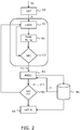
- the general principle of the invention is based on the division of a three-dimensional scene into a plurality of planes parallel to the plane of the hologram and on a hybrid digital hologram generation solution, implementing a first point-based technique for shots with a limited number of points in the non-zero amplitude scene and a second field based technique for shots with more points in the scene.
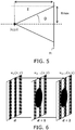
- the planes P i are situated at equal distance of z from one another.
- P 0 is the plane farthest from the plane of the hologram, at the distance z max of P H and P N z -1 is the plane closest to the plane of the hologram, at the distance z min of P H , with z min ⁇ z max .
- the planes P 0 , ... P N z -1 and the plane of the hologram P H are sampled on a regular grid of resolution N ⁇ N with a sampling step p.
- the portion of scene included in the plane P i with i integer between 0 and N z -1, will be designated as the edge of the three-dimensional scene Sc between the plane P i and the plane P i +1 .
- the planes P 0 to P N z -1 are processed successively from the farthest to the nearest hologram.
- the first plane P 0 and the last plane P N z -1 are processed according to the field-based method.
- a threshold M i , max is evaluated from an estimation of a processing time of the current plan according to the first method and a computation time of the current plan according to the second method.
- An example of calculation of the value of the threshold M i , max will be detailed in the following description.
- the planes P 0 , P 3 and P 7 are field-based plans.
- the planes P 1 , P 2 , P 4 , P 5 and P 6 are so-called "point-based" plans.
- the current plane P i is processed according to the chosen propagation technique. This step provides the total light wave u i emitted by this plane. Advantageously, it is stored in a memory M1.
- step E7 the propagation of the light wave u N z -1 emitted by the last plane P N z -1 on the plane of the hologram is calculated according to the field-based propagation technique and the result is obtained.
- hologram H the propagation of the light wave u N z -1 emitted by the last plane P N z -1 on the plane of the hologram is calculated according to the field-based propagation technique and the result is obtained.
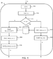
- E41 we identify among the previous plans, already processed, the plan based on the nearest field or last plan based field.
- It is the plane P0.
- I the index I, with I integer between 0 and Nz-1.
- the amplitude a i ( x , y ) is calculated using an illumination model, for example that described by Phong in the article “Illumination for Computer Generated Pictures” published in Volume 18, Issue 6 of the journal “Communications of the ACM", pp. 311-317, 1975 .
- the propagation of the complex light waves emitted by the preceding planes from the previous field-based plane PI to Pi-1 is calculated, namely in the example of the Figure 3 P0, P1 and P2, up to the current plane Pi according to the T1 or T2 propagation technique chosen for each previous plane.
- FFT Fast Fourier Transform
- P w is O (N 2 log (N)).
- ⁇ j denotes the light wave emitted by the intermediate plane P j.
- the light wave u j , u 2 is obtained by implementing the processing step E4 according to the invention in the case of a "point-based" plan. It will be detailed in the following description.
- the propagation of the light wave uj of a plane Pj based on the plane Pi is thus calculated using the first so-called point-based technique.
- the points of the scene situated in each plane are considered as spherical light sources and the propagation of the light coming from this plane to the plane Pi is calculated as the sum of the spherical waves emitted by each of the planes. points of the plan.
- the correspondence table is pre-calculated only in the square circumscribed to the disk defined by the window function h.
- the light waves oj emitted by all the preceding planes are propagated from the field based plane P 1 directly on the current field based plane.
- An advantage of the proposed solution is that it only deals with propagations of a light wave from a field-based plane to another field-based plane or a point-based plane on a field-based plane, which are relatively simple to calculate.
- the areas of the current plane P i are represented in the form of extended line segments for which the occulting bitmask m i is 0.
- the occulting bit mask is equal to 1.
- this plane P i is a plane interposed between two successive field-based planes, a previous plane P 1 , with 1 ⁇ i and a following plane P d , with d> i, as illustrated by FIG. Figure 8 .
- the processing step E 4 implements the substep E 42 already described for calculating the light wave o i emitted by the points of the scene portion included in the plane P i which have a non-zero amplitude according to the equation (2) already described.
- E 47 we calculate the amplitude of the light waves emitted by previous planes from the field-based plane P I to the plane P i -1 , and blocked by occulting obstacles of the scene included in P i . Once again, these are points in the scene that have a non-zero amplitude. It is therefore a question of managing the occultations of the light waves coming from the preceding plans, by a plane based points.
- the technique for taking into account occlusions described in connection with the Figures 6 and 7 for field based plans is not at all suited to point based plans. Indeed, this technique requires to calculate beforehand the propagation of light waves step by step, that is to say from a previous plane on the current plane based points. However, at each diffraction stage, the complex wave emitted by the scene gradually extends from one plane to another, and the incident wave on the plane P i can extend over a large number of samples.
- the total light wave ui 'emitted by this plane can have a large number of non-zero values.
- Each non-zero value of the wave u i is then considered as a spherical light source by the propagation operator P s previously described.
- the incident wave will illuminate a certain number of additional points in the plane based on current points and complicate the subsequent processing of this plane.
- the algorithmic complexity of P s depends on the number of spherical light sources located in the source plane.
- the invention proposes a different approach, adapted to point-based plans. It consists in calculating the amplitude of the light wave coming from the preceding planes only for the points of non-zero amplitude of the scene of the current plane Pi '.
- this calculation is based on an inverted binary mask. It provides the amplitude of the light wave blocked by the current plane.
- the use of the inverted binary mask has the advantage of not increasing the number of spherical light sources whose wave must be calculated at each diffraction step. This technique is thus extremely effective for taking into account occultations by point-based plans.
- the total light wave ui emitted by the plane Pi is calculated by subtracting the wave o bi blocked from the light wave emitted by the scene portion included in the plane P i .
- T i s corresponds to the sum of the time required to calculate the occultation of the light wave by the plane Pi by using the inverted binary mask technique (step E47) and the time required to calculate the propagation of the light wave emitted by the plane P i using the operator P s (step E44):
- T d s ⁇ M d M + ⁇ M d NOT 2
- ⁇ and ⁇ are constant coefficients
- M is the total number of points of the scene located in the index plan j between l and i-1 and N 2 the total number of pixels of the hologram H:
- An advantage of this embodiment of the invention is that it makes it possible to determine the most suitable technique for processing the current plan on the basis of a realistic comparison of the calculation times associated with the two methods put in competition.
- the evaluation of the threshold may advantageously be implemented during a first preprocessing pass of the plurality of planes.
- the number of points per plane based on points taken into account in the method remains unchanged and equal to the number of non-zero amplitude points of the scene Sc. original.
- the threshold M d, max could equally well be evaluated from calculation complexity estimates of the first and second methods for the current plan rather than from time estimates. calculation, so as to remain independent of any implementation optimizations of the method on a particular system.
- the occulting plane P i is divided into zones A to H.
- these zones have simple geometric shapes, typically rectangular and all have the same dimensions.
- Each point q j of the plane Pi thus only conceals the light coming from the points p k of the plane P i -1 which illuminate the area in which it is located.
- the point q 1 ⁇ B only occludes the light from the points in the list l ( B ), that is, the light from p 1 .
- step E47 the computational complexity of step E47 is therefore reduced.
- module and/or entity
- module may correspond to either a software component or a component hardware, or to a set of hardware and / or software components, capable of implementing the function or functions described for the module or entity concerned.
- the device 100 comprises a processing unit 110, equipped with a processor u1, and driven by a computer program Pg1 120, stored in a memory 130 and implementing the method according to the invention.
- the code instructions of the computer program Pg 1 120 are for example loaded into a RAM before being executed by the processor of the processing unit 110.
- the processor of the processing unit 110 implements the steps of the method described above, in these different embodiments, according to the instructions of the computer program 120.
- the device 100 comprises at least one CARD unit for counting a number of points of the non-zero amplitude scene in the current plane, a DEC unit of choice of a first or a second propagation technique of a light wave emitted by the current plane as a function of a number of points of non-zero amplitude of the portion of the scene included in the current plane and a predetermined threshold value, the first technique, so-called points, intended to calculate a sum of light waves emitted by point sources constituted by the points of the non-zero amplitude scene portion of the current plane on a following plane, the second technique, so-called field-based , able to calculate globally a light wave emitted by the scene portion included in the current plane on a following plane, a processing unit of the current plane according to the chosen propagation technique, able to calculate a a light emitted from the current plane and a GET H unit for obtaining the hologram from the light waves calculated for the plurality of planes.
- the first technique so-
- the PROC processing unit of the current plan comprises subunits of identification of the last plane based on the treated field, calculation of the light wave emitted by the scene portion included in the current plane and optionally, according to the technique. chosen, a subunit for calculating the light wave propagated from the preceding planes, a subunit of computation the light wave occulted by the current plane and a sub unit of calculation of the total light wave u i emitted by the current plane.
- the device 100 further comprises a light-wave storage unit M 1 calculated for the plurality of planes. These units are driven by the processor ⁇ 1 of the processing unit 110.
- such a device 100 can be integrated with a user terminal TU.
- a terminal may be a personal computer (for "personal computer", in English), a tablet, a smartphone (for "smartphone” in English) or any hardware and / or software system including sufficient computing resources to implement the method according to the invention.
- a terminal furthermore comprises a control module via wire connection means or not, a DR rendering device, such as a 2D, 3D or holographic 3D television, capable of reproducing the hologram generated by the method. according to the invention.
- a DR rendering device such as a 2D, 3D or holographic 3D television, capable of reproducing the hologram generated by the method.
- it is necessary to provide, for example within the control module MC, an intermediate processing of adaptation of the generous light field in order to make it viewable on the rendering device DR.
- the invention which has just been presented makes it possible to digitally generate a hologram light field from a three-dimensional scene.
- FIG. 11 another example of a possible use of the invention is now presented. It is considered that there is a first hologram H which has been generated using the method of the invention or another method. We do not know a priori the first scene at the origin of the H hologram.
- the so-called enhanced holography scenario we want to integrate a second scene including at least one additional object in front of the first scene.
- the second scene is limited to an object, in this case a rabbit. To be able to integrate properly in the scene, the rabbit must correctly hide the elements of the first scene behind him.
- the new hologram H ' is obtained by propagation of the light wave U Nz-1 calculated for the last field-based plane P Nz-1 on the plane of the hologram H'. Then, it is possible to propagate the light field H 'obtained in the plane H to maintain the position of the original hologram and to see the second scene appear in front of the first.
Landscapes
- Physics & Mathematics (AREA)
- General Physics & Mathematics (AREA)
- Engineering & Computer Science (AREA)
- Computing Systems (AREA)
- Theoretical Computer Science (AREA)
- Holo Graphy (AREA)
Claims (12)
- Verfahren zur digitalen Erzeugung eines Hologramms (H) in einer Ebene (PH), die als Hologrammebene bezeichnet wird, aus einer dreidimensionalen Szene (Sc), umfassend einen Schritt (E0) des Schneidens der Szene in eine Vielzahl von Ebenen (P0, ..., PNz-1) parallel zur Hologrammebene, dadurch gekennzeichnet, dass das Verfahren die folgenden Schritte umfasst, welche für eine Ebene (Pi) der Vielzahl von Ebenen, die als aktuelle Ebene bezeichnet wird, durchgeführt werden, wobei die Ebenen von der am weitesten von der Hologrammebene entfernten zu der dieser nächstliegenden durchlaufen werden:- Zählen (E1) einer Anzahl von Punkten (MI) der Szene mit einer Amplitude von Nicht-Null in der aktuellen Ebene;- Wählen (E2) einer ersten oder einer zweiten Technik (T1, T2) der Ausbreitung einer Lichtwelle, die von der aktuellen Ebene emittiert wird, als Funktion der Anzahl von Punkten mit einer Amplitude von Nicht-Null des Abschnitts der Szene, der in der aktuellen Ebene enthalten ist, und eines vorherbestimmten Schwellenwerts (MI,max), wobei die erste Technik (T1), die als punktbasiert bezeichnet wird, dazu bestimmt ist, die Ausbreitung einer Summe von Lichtwellen, die von Punktquellen emittiert werden, bestehend aus den Punkten des Abschnitts der Szene mit einer Amplitude von Nicht-Null, von der aktuellen Ebene in einer folgenden Ebene zu berechnen, wobei die zweite Technik (T2), die als feldbasiert bezeichnet wird, dazu bestimmt ist, global die Ausbreitung eines Lichtfelds, das von dem Abschnitt der Szene emittiert wird, der in der aktuellen Ebene enthalten ist, in einer folgenden Ebene zu bestimmen, wobei die erste Technik gewählt wird, wenn die Anzahl von Punkten streng kleiner ist als der vorherbestimmte Schwellenwert, und die zweite, wenn nicht;- Behandeln (E4) der aktuellen Ebene als Funktion der gewählten Ausbreitungstechnik, die dazu bestimmt ist, eine Lichtwelle (ui) zu berechnen, die von der aktuellen Ebene emittiert wird;wobei die Schritte für die Vielzahl von Ebenen wiederholt werden,
und dadurch, dass das Verfahren außerdem einen Schritt (E6) des Erhaltens des Hologramms aus den Lichtwellen umfasst, die für die Vielzahl von Ebenen berechnet werden. - Verfahren zur digitalen Erzeugung eines Hologramms nach Anspruch 1, dadurch gekennzeichnet, dass der Schritt (E4) des Behandelns der aktuellen Ebene die folgenden Teilschritte umfasst:- Identifizieren (E41) der letzten Ebene, die gemäß der zweiten Technik behandelt wurde, die als letzte feldbasierte Ebene (PI) bezeichnet wird;- Berechnen (E42) der Lichtwelle, die von dem Abschnitt der Szene emittiert wird, der in der aktuellen Ebene enthalten ist;- wobei, wenn die zweite Technik für die aktuelle Ebene gewählt wurde, die als feldbasierte Ebene bezeichnet wird, der Behandlungsschritt außerdem die folgenden Teilschritte umfasst:dadurch, dass der Schritt (E6) des Erhaltens des Hologramms die Berechnung der Ausbreitung der Lichtwelle, welche von der feldbasierten Ebene emittiert wird, die dem Hologramm am nächsten liegt (PNz-1), in der Hologrammebene (PH) umfasst.∘ Berechnen (E44) einer Ausbreitung der Lichtwelle, die mindestens von der letzten feldbasierten Ebene (PI) emittiert wird, in der ersten Ebene, gemäß der für die Ebene gewählten Technik;∘ Berechnen (E46) der Lichtwelle, die von der aktuellen Ebene emittiert wird, durch Summierung der Lichtwelle, die von der aktuellen Ebene emittiert wird, und mindestens der Ausbreitung der Lichtwelle, die mindestens von der letzten feldbasierten Ebene emittiert wird; und
- Verfahren zur digitalen Erzeugung eines Hologramms nach Anspruch 2, dadurch gekennzeichnet, dass, wenn die mindestens eine vorhergehende Ebene außerdem mindestens eine punktbasierte Ebene (Pj) umfasst, die zwischen der letzten feldbasierten Ebene und der aktuellen Ebene angeordnet ist, die Berechnung der Ausbreitung der Lichtwelle, die mindestens von der letzten feldbasierten Ebene emittiert wird, in der aktuellen Ebene (Pi) außerdem die Berechnung einer Ausbreitung der Lichtwelle, die von den Punkten mit einer Amplitude von Nicht-Null des Abschnitts der Szene emittiert wird, der in der mindestens einen dazwischenliegenden Ebene enthalten ist, in der aktuellen Ebene gemäß der ersten Technik umfasst.
- Verfahren zur digitalen Erzeugung eines Hologramms nach einem der Ansprüche 2 und 3, dadurch gekennzeichnet, dass der Schritt (E4) des Behandelns der aktuellen Ebene einen Teilschritt (E45) der Steuerung einer Abdeckung der Lichtwelle, die mindestens von der letzten feldbasierten Ebene (PI) ausgebreitet wird, in der aktuellen Ebene umfasst, durch Anlegen einer binären Abdeckmaske (mi) an die Lichtwelle, wobei die Maske einen Wert von Null an den Punkten des Abschnitts der Szene, der in der aktuellen Ebene (Pj) enthalten ist, und einen Wert von Nicht-Null außerhalb dieses Abschnitts annimmt, und dadurch, dass der Teilschritt (E46) der Berechnung der Lichtwelle (ui), die von der aktuellen Ebene emittiert wird, eine Summierung der Lichtwelle (oi), die von der aktuellen Ebene emittiert wird, mit der Lichtwelle, die nach dem Anlegen der binären Abdeckmaske (mi) erhalten wird, umfasst.
- Verfahren zur digitalen Erzeugung eines Hologramms nach einem der Ansprüche 3 und 4, dadurch gekennzeichnet, dass, wenn die erste Technik gewählt wurde, um die aktuelle Ebene zu behandeln, die als punktbasierte Ebene bezeichnet wird, der Behandlungsschritt (E4) außerdem die folgenden Teilschritte umfasst:- Berechnen (E47) einer Lichtwelle (obi), die mindestens von der letzten feldbasierten Ebene (PI) emittiert wird, gemäß der ersten Technik, und die durch die Punkte mit einer Amplitude von Nicht-Null des Abschnitts der Szene blockiert wird, der in der aktuellen Ebene enthalten ist;- Berechnen (E48) der Lichtwelle (ui), die von der aktuellen Ebene emittiert wird, durch Subtraktion der Lichtwelle (obi), die durch die Punkte mit einer Amplitude von Nicht-Null des Abschnitts der Szene blockiert wird, der in der aktuellen Ebene enthalten ist, von der Lichtwelle (oi), die von den Punkten emittiert wird.
- Verfahren zur digitalen Erzeugung eines Hologramms nach Anspruch 5, dadurch gekennzeichnet, dass der Teilschritt (E47) der Berechnung der blockierten Lichtwelle umfasst: die Berechnung der Lichtwelle, die mindestens von der letzten feldbasierten Ebene (PI) emittiert wird, gemäß der ersten Technik, und das Anlegen einer inversen binären Abdeckmaske (ai) an die berechnete Lichtwelle, wobei die Maske einen Wert von Nicht-Null an den Punkten des Abschnitts der Szene, der in der aktuellen Ebene enthalten ist, und einen Wert von Null außerhalb dieses Abschnitts annimmt.
- Verfahren zur digitalen Erzeugung eines Hologramms nach Anspruch 6, dadurch gekennzeichnet, dass der Teilschritt (E47) der Berechnung der blockierten Lichtwelle umfasst: ein Schneiden der aktuellen Ebene in eine Vielzahl von Zonen, eine Bestimmung der Punkte einer vorhergehenden Ebene aus der letzten feldbasierten Ebene, die beitragen zur Ausbreitung einer Lichtwelle in mindestens einer Zone der Vielzahl von Zonen, umfassend Punkte mit einer Amplitude von Nicht-Null des Abschnitts der Szene, der in der aktuellen Ebene enthalten ist, wobei die Berechnung der blockierten Lichtwelle nur für die bestimmten Punkte durchgeführt wird.
- Verfahren zur digitalen Erzeugung eines Hologramms nach einem der vorhergehenden Ansprüche, dadurch gekennzeichnet, dass dieses einen Schritt (E3) der Evaluierung einer Schwelle (MI,max) mindestens als Funktion einer Behandlungszeit, die für die erste Ausbreitungstechnik geschätzt wird, einer Behandlungszeit, die für die zweite Ausbreitungstechnik geschätzt wird, für die aktuelle Ebene und einer Anzahl von Punkten mit einer Amplitude von Nicht-Null des Abschnitts der Szene, der in den vorhergehenden Ebenen enthalten ist.
- Vorrichtung (100) zur digitalen Erzeugung eines Hologramms (H) in einer Ebene (PH), die als Hologrammebene bezeichnet wird, aus einer dreidimensionalen Szene (Sc), umfassend eine Einheit (CUT) zum Schneiden der Szene in eine Vielzahl von Ebenen (P0, ..., PNz-1) parallel zur Hologrammebene, dadurch gekennzeichnet, dass die Vorrichtung die folgenden Einheiten umfasst, die geeignet sind zum:- Zählen (CARD) einer Anzahl von Punkten der Szene mit einer Amplitude von Nicht-Null in der aktuellen Ebene;- Wählen (DEC) einer ersten oder einer zweiten Technik der Ausbreitung einer Lichtwelle, die von der aktuellen Ebene emittiert wird, als Funktion der Anzahl von Punkten mit einer Amplitude von Nicht-Null des Abschnitts der Szene, der in der aktuellen Ebene enthalten ist, und eines vorherbestimmten Schwellenwerts, wobei die erste Technik (T1), die als punktbasiert bezeichnet wird, dazu bestimmt ist, eine Summe von Lichtwellen, die von Punktquellen emittiert werden, bestehend aus den Punkten des Abschnitts der Szene mit einer Amplitude von Nicht-Null, von der aktuellen Ebene in der folgenden Ebene zu berechnen, wobei die zweite Technik (T2), die als feldbasiert bezeichnet wird, dazu bestimmt ist, global eine Lichtwelle, die von dem Abschnitt der Szene emittiert wird, der in der aktuellen Ebene enthalten ist, in einer folgenden Ebene zu bestimmen, wobei die erste Technik ausgewählt wird, wenn die Anzahl von Punkten streng kleiner ist als der vorherbestimmte Schwellenwert, und die zweite, wenn nicht;- Behandeln (PROC) der aktuellen Ebene gemäß der gewählten Ausbreitungstechnik, die dazu bestimmt ist, eine Lichtwelle zu berechnen, die von der aktuellen Ebene emittiert wird;wobei die Verwendung der Einheiten für die Vielzahl von Ebenen wiederholt wird,
und dadurch, dass die Vorrichtung außerdem eine Einheit (GET H) zum Erhalten des Hologramms aus den Lichtwellen umfasst, die für die Vielzahl von Ebenen berechnet werden. - Benutzerterminal (TU), umfassend ein Steuermodul (MC) einer Vorrichtung zur Wiederherstellung (DR) eines Hologramms (H), dadurch gekennzeichnet, dass dieses außerdem eine Vorrichtung (100) zur digitalen Erzeugung des Hologramms nach Anspruch 9 umfasst.
- Computerprogramm (Pg1), umfassend Instruktionen zur Durchführung des Verfahrens nach einem der Ansprüche 1 bis 8, wenn dieses von einem Prozessor ausgeführt wird.
- Prozessorlesbares Speichermedium, welches ein Computerprogramm speichert, umfassend Programmcodeinstruktionen zur Ausführung der Schritte des Verfahrens nach einem der Ansprüche 1 bis 8.
Applications Claiming Priority (2)
| Application Number | Priority Date | Filing Date | Title |
|---|---|---|---|
| FR1554363A FR3036197B1 (fr) | 2015-05-13 | 2015-05-13 | Procede de generation numerique d'un hologramme, dispositif et programme d'ordinateur associes |
| PCT/FR2016/051087 WO2016181061A1 (fr) | 2015-05-13 | 2016-05-10 | Procede de generation numerique d'un hologramme, dispositif et programme d'ordinateur associes |
Publications (2)
| Publication Number | Publication Date |
|---|---|
| EP3295258A1 EP3295258A1 (de) | 2018-03-21 |
| EP3295258B1 true EP3295258B1 (de) | 2019-07-10 |
Family
ID=53674172
Family Applications (1)
| Application Number | Title | Priority Date | Filing Date |
|---|---|---|---|
| EP16726140.3A Active EP3295258B1 (de) | 2015-05-13 | 2016-05-10 | Verfahren zur digitalen erzeugung eines hologramms, zugehörige vorrichtung und computerprogramm |
Country Status (4)
| Country | Link |
|---|---|
| US (1) | US10474102B2 (de) |
| EP (1) | EP3295258B1 (de) |
| FR (1) | FR3036197B1 (de) |
| WO (1) | WO2016181061A1 (de) |
-
2015
- 2015-05-13 FR FR1554363A patent/FR3036197B1/fr active Active
-
2016
- 2016-05-10 EP EP16726140.3A patent/EP3295258B1/de active Active
- 2016-05-10 US US15/573,723 patent/US10474102B2/en active Active
- 2016-05-10 WO PCT/FR2016/051087 patent/WO2016181061A1/fr not_active Ceased
Non-Patent Citations (1)
| Title |
|---|
| None * |
Also Published As
| Publication number | Publication date |
|---|---|
| FR3036197B1 (fr) | 2017-10-06 |
| US20180143589A1 (en) | 2018-05-24 |
| US10474102B2 (en) | 2019-11-12 |
| WO2016181061A1 (fr) | 2016-11-17 |
| FR3036197A1 (fr) | 2016-11-18 |
| EP3295258A1 (de) | 2018-03-21 |
Similar Documents
| Publication | Publication Date | Title |
|---|---|---|
| EP3646121B1 (de) | Verfahren zur digitalen generierung eines hologramms, vorrichtung, endgerät, zugehöriges system und computerprogramm | |
| EP0921449B1 (de) | Rechnergestütztes holographisches Verfahren und Vorrichtung | |
| EP1008919A1 (de) | Computergestütztes Verfahren und Vorrichtung zur Wiedergabe von dreidimensionalen Bildern | |
| Blinder | Direct calculation of computer-generated holograms in sparse bases | |
| EP2815281B1 (de) | Verfahren zur codierung eines holographischen musters und zugehörige codierungsvorrichtung und computerprogramm | |
| WO2021004797A1 (fr) | Procédé et dispositif de codage d'une séquence d'hologrammes numériques | |
| EP3123721B1 (de) | System und verfahren zur datenverarbeitung | |
| EP2504816B1 (de) | Verfahren zur schätzung von lichtstreuung | |
| EP3350656A1 (de) | Verfahren zur verarbeitung eines holografischen bildes | |
| EP3785083B1 (de) | Verfahren zur verarbeitung eines hologramms, zugehörige vorrichtung, holografisches anzeigesystem und computerprogramm | |
| WO2016181061A1 (fr) | Procede de generation numerique d'un hologramme, dispositif et programme d'ordinateur associes | |
| EP3814850B1 (de) | Verfahren zur erzeugung eines digitalen hologramms, zugehörige vorrichtung, holographisches anzeigesystem und computerprogramm | |
| WO2012000847A2 (fr) | Procede d'estimation de diffusion de la lumiere | |
| WO2011057997A2 (fr) | Procede d'estimation de diffusion de la lumiere | |
| WO2011058007A2 (fr) | Procede d'estimation de diffusion de la lumiere | |
| WO2000042575A1 (fr) | Procede de simplification d'un maillage source, tenant compte de la courbure locale et de la dynamique geometrique locale, et applications correspondantes | |
| EP4287122B1 (de) | Verfahren zur erzeugung eines reliefdarstellungsmodells mittels photogrammetrie | |
| EP0921450A1 (de) | Verfahren und Vorrichtung zur Synthese von Hologrammen | |
| FR3137980A1 (fr) | Hologramme physique fabriqué à partir d’un hologramme numérique et dispositif holographique associé | |
| WO2026087114A1 (fr) | Procédé et dispositif de représentation de contenu volumétrique | |
| WO2026087113A1 (fr) | Procédé et dispositif de représentation par couche de contenu volumétrique | |
| FR3168054A3 (fr) | Procédé et dispositif de représentation de contenu volumétrique. | |
| EP2204775B1 (de) | Inkrementelle Triangulierung von Polygonen für eine digitale Anzeige | |
| FR3168057A3 (fr) | Procédé et dispositif de représentation de contenu volumétrique. | |
| Chariot | Quelques Applications de la Programmation des Processeurs Graphiques à la Simulation Neuronale et à la Vision par Ordinateur |
Legal Events
| Date | Code | Title | Description |
|---|---|---|---|
| STAA | Information on the status of an ep patent application or granted ep patent |
Free format text: STATUS: THE INTERNATIONAL PUBLICATION HAS BEEN MADE |
|
| PUAI | Public reference made under article 153(3) epc to a published international application that has entered the european phase |
Free format text: ORIGINAL CODE: 0009012 |
|
| STAA | Information on the status of an ep patent application or granted ep patent |
Free format text: STATUS: REQUEST FOR EXAMINATION WAS MADE |
|
| 17P | Request for examination filed |
Effective date: 20171002 |
|
| AK | Designated contracting states |
Kind code of ref document: A1 Designated state(s): AL AT BE BG CH CY CZ DE DK EE ES FI FR GB GR HR HU IE IS IT LI LT LU LV MC MK MT NL NO PL PT RO RS SE SI SK SM TR |
|
| AX | Request for extension of the european patent |
Extension state: BA ME |
|
| DAV | Request for validation of the european patent (deleted) | ||
| DAX | Request for extension of the european patent (deleted) | ||
| RAP1 | Party data changed (applicant data changed or rights of an application transferred) |
Owner name: B COM |
|
| REG | Reference to a national code |
Ref country code: DE Ref legal event code: R079 Ref document number: 602016016675 Country of ref document: DE Free format text: PREVIOUS MAIN CLASS: G03H0001080000 Ipc: G03H0001040000 |
|
| GRAP | Despatch of communication of intention to grant a patent |
Free format text: ORIGINAL CODE: EPIDOSNIGR1 |
|
| RIC1 | Information provided on ipc code assigned before grant |
Ipc: G03H 1/04 20060101AFI20190118BHEP Ipc: G03H 1/08 20060101ALI20190118BHEP Ipc: G03H 1/26 20060101ALI20190118BHEP |
|
| STAA | Information on the status of an ep patent application or granted ep patent |
Free format text: STATUS: GRANT OF PATENT IS INTENDED |
|
| INTG | Intention to grant announced |
Effective date: 20190228 |
|
| GRAS | Grant fee paid |
Free format text: ORIGINAL CODE: EPIDOSNIGR3 |
|
| GRAA | (expected) grant |
Free format text: ORIGINAL CODE: 0009210 |
|
| STAA | Information on the status of an ep patent application or granted ep patent |
Free format text: STATUS: THE PATENT HAS BEEN GRANTED |
|
| AK | Designated contracting states |
Kind code of ref document: B1 Designated state(s): AL AT BE BG CH CY CZ DE DK EE ES FI FR GB GR HR HU IE IS IT LI LT LU LV MC MK MT NL NO PL PT RO RS SE SI SK SM TR |
|
| REG | Reference to a national code |
Ref country code: GB Ref legal event code: FG4D Free format text: NOT ENGLISH |
|
| REG | Reference to a national code |
Ref country code: CH Ref legal event code: EP Ref country code: AT Ref legal event code: REF Ref document number: 1154219 Country of ref document: AT Kind code of ref document: T Effective date: 20190715 |
|
| REG | Reference to a national code |
Ref country code: DE Ref legal event code: R096 Ref document number: 602016016675 Country of ref document: DE |
|
| REG | Reference to a national code |
Ref country code: IE Ref legal event code: FG4D Free format text: LANGUAGE OF EP DOCUMENT: FRENCH |
|
| REG | Reference to a national code |
Ref country code: DE Ref legal event code: R082 Ref document number: 602016016675 Country of ref document: DE Ref country code: DE Ref legal event code: R082 Ref document number: 602016016675 Country of ref document: DE Representative=s name: HELLMICH, WOLFGANG, DIPL.-PHYS.UNIV. DR.-ING., DE |
|
| REG | Reference to a national code |
Ref country code: NL Ref legal event code: MP Effective date: 20190710 |
|
| REG | Reference to a national code |
Ref country code: LT Ref legal event code: MG4D |
|
| REG | Reference to a national code |
Ref country code: AT Ref legal event code: MK05 Ref document number: 1154219 Country of ref document: AT Kind code of ref document: T Effective date: 20190710 |
|
| PG25 | Lapsed in a contracting state [announced via postgrant information from national office to epo] |
Ref country code: NL Free format text: LAPSE BECAUSE OF FAILURE TO SUBMIT A TRANSLATION OF THE DESCRIPTION OR TO PAY THE FEE WITHIN THE PRESCRIBED TIME-LIMIT Effective date: 20190710 Ref country code: PT Free format text: LAPSE BECAUSE OF FAILURE TO SUBMIT A TRANSLATION OF THE DESCRIPTION OR TO PAY THE FEE WITHIN THE PRESCRIBED TIME-LIMIT Effective date: 20191111 Ref country code: BG Free format text: LAPSE BECAUSE OF FAILURE TO SUBMIT A TRANSLATION OF THE DESCRIPTION OR TO PAY THE FEE WITHIN THE PRESCRIBED TIME-LIMIT Effective date: 20191010 Ref country code: SE Free format text: LAPSE BECAUSE OF FAILURE TO SUBMIT A TRANSLATION OF THE DESCRIPTION OR TO PAY THE FEE WITHIN THE PRESCRIBED TIME-LIMIT Effective date: 20190710 Ref country code: NO Free format text: LAPSE BECAUSE OF FAILURE TO SUBMIT A TRANSLATION OF THE DESCRIPTION OR TO PAY THE FEE WITHIN THE PRESCRIBED TIME-LIMIT Effective date: 20191010 Ref country code: HR Free format text: LAPSE BECAUSE OF FAILURE TO SUBMIT A TRANSLATION OF THE DESCRIPTION OR TO PAY THE FEE WITHIN THE PRESCRIBED TIME-LIMIT Effective date: 20190710 Ref country code: AT Free format text: LAPSE BECAUSE OF FAILURE TO SUBMIT A TRANSLATION OF THE DESCRIPTION OR TO PAY THE FEE WITHIN THE PRESCRIBED TIME-LIMIT Effective date: 20190710 Ref country code: LT Free format text: LAPSE BECAUSE OF FAILURE TO SUBMIT A TRANSLATION OF THE DESCRIPTION OR TO PAY THE FEE WITHIN THE PRESCRIBED TIME-LIMIT Effective date: 20190710 Ref country code: FI Free format text: LAPSE BECAUSE OF FAILURE TO SUBMIT A TRANSLATION OF THE DESCRIPTION OR TO PAY THE FEE WITHIN THE PRESCRIBED TIME-LIMIT Effective date: 20190710 |
|
| PG25 | Lapsed in a contracting state [announced via postgrant information from national office to epo] |
Ref country code: LV Free format text: LAPSE BECAUSE OF FAILURE TO SUBMIT A TRANSLATION OF THE DESCRIPTION OR TO PAY THE FEE WITHIN THE PRESCRIBED TIME-LIMIT Effective date: 20190710 Ref country code: IS Free format text: LAPSE BECAUSE OF FAILURE TO SUBMIT A TRANSLATION OF THE DESCRIPTION OR TO PAY THE FEE WITHIN THE PRESCRIBED TIME-LIMIT Effective date: 20191110 Ref country code: ES Free format text: LAPSE BECAUSE OF FAILURE TO SUBMIT A TRANSLATION OF THE DESCRIPTION OR TO PAY THE FEE WITHIN THE PRESCRIBED TIME-LIMIT Effective date: 20190710 Ref country code: GR Free format text: LAPSE BECAUSE OF FAILURE TO SUBMIT A TRANSLATION OF THE DESCRIPTION OR TO PAY THE FEE WITHIN THE PRESCRIBED TIME-LIMIT Effective date: 20191011 Ref country code: RS Free format text: LAPSE BECAUSE OF FAILURE TO SUBMIT A TRANSLATION OF THE DESCRIPTION OR TO PAY THE FEE WITHIN THE PRESCRIBED TIME-LIMIT Effective date: 20190710 Ref country code: AL Free format text: LAPSE BECAUSE OF FAILURE TO SUBMIT A TRANSLATION OF THE DESCRIPTION OR TO PAY THE FEE WITHIN THE PRESCRIBED TIME-LIMIT Effective date: 20190710 |
|
| PG25 | Lapsed in a contracting state [announced via postgrant information from national office to epo] |
Ref country code: TR Free format text: LAPSE BECAUSE OF FAILURE TO SUBMIT A TRANSLATION OF THE DESCRIPTION OR TO PAY THE FEE WITHIN THE PRESCRIBED TIME-LIMIT Effective date: 20190710 |
|
| PG25 | Lapsed in a contracting state [announced via postgrant information from national office to epo] |
Ref country code: EE Free format text: LAPSE BECAUSE OF FAILURE TO SUBMIT A TRANSLATION OF THE DESCRIPTION OR TO PAY THE FEE WITHIN THE PRESCRIBED TIME-LIMIT Effective date: 20190710 Ref country code: DK Free format text: LAPSE BECAUSE OF FAILURE TO SUBMIT A TRANSLATION OF THE DESCRIPTION OR TO PAY THE FEE WITHIN THE PRESCRIBED TIME-LIMIT Effective date: 20190710 Ref country code: IT Free format text: LAPSE BECAUSE OF FAILURE TO SUBMIT A TRANSLATION OF THE DESCRIPTION OR TO PAY THE FEE WITHIN THE PRESCRIBED TIME-LIMIT Effective date: 20190710 Ref country code: RO Free format text: LAPSE BECAUSE OF FAILURE TO SUBMIT A TRANSLATION OF THE DESCRIPTION OR TO PAY THE FEE WITHIN THE PRESCRIBED TIME-LIMIT Effective date: 20190710 Ref country code: PL Free format text: LAPSE BECAUSE OF FAILURE TO SUBMIT A TRANSLATION OF THE DESCRIPTION OR TO PAY THE FEE WITHIN THE PRESCRIBED TIME-LIMIT Effective date: 20190710 |
|
| PG25 | Lapsed in a contracting state [announced via postgrant information from national office to epo] |
Ref country code: IS Free format text: LAPSE BECAUSE OF FAILURE TO SUBMIT A TRANSLATION OF THE DESCRIPTION OR TO PAY THE FEE WITHIN THE PRESCRIBED TIME-LIMIT Effective date: 20200224 Ref country code: SK Free format text: LAPSE BECAUSE OF FAILURE TO SUBMIT A TRANSLATION OF THE DESCRIPTION OR TO PAY THE FEE WITHIN THE PRESCRIBED TIME-LIMIT Effective date: 20190710 Ref country code: CZ Free format text: LAPSE BECAUSE OF FAILURE TO SUBMIT A TRANSLATION OF THE DESCRIPTION OR TO PAY THE FEE WITHIN THE PRESCRIBED TIME-LIMIT Effective date: 20190710 Ref country code: SM Free format text: LAPSE BECAUSE OF FAILURE TO SUBMIT A TRANSLATION OF THE DESCRIPTION OR TO PAY THE FEE WITHIN THE PRESCRIBED TIME-LIMIT Effective date: 20190710 |
|
| REG | Reference to a national code |
Ref country code: DE Ref legal event code: R097 Ref document number: 602016016675 Country of ref document: DE |
|
| PLBE | No opposition filed within time limit |
Free format text: ORIGINAL CODE: 0009261 |
|
| STAA | Information on the status of an ep patent application or granted ep patent |
Free format text: STATUS: NO OPPOSITION FILED WITHIN TIME LIMIT |
|
| PG2D | Information on lapse in contracting state deleted |
Ref country code: IS |
|
| 26N | No opposition filed |
Effective date: 20200603 |
|
| PG25 | Lapsed in a contracting state [announced via postgrant information from national office to epo] |
Ref country code: SI Free format text: LAPSE BECAUSE OF FAILURE TO SUBMIT A TRANSLATION OF THE DESCRIPTION OR TO PAY THE FEE WITHIN THE PRESCRIBED TIME-LIMIT Effective date: 20190710 |
|
| PG25 | Lapsed in a contracting state [announced via postgrant information from national office to epo] |
Ref country code: CH Free format text: LAPSE BECAUSE OF NON-PAYMENT OF DUE FEES Effective date: 20200531 Ref country code: LI Free format text: LAPSE BECAUSE OF NON-PAYMENT OF DUE FEES Effective date: 20200531 Ref country code: MC Free format text: LAPSE BECAUSE OF FAILURE TO SUBMIT A TRANSLATION OF THE DESCRIPTION OR TO PAY THE FEE WITHIN THE PRESCRIBED TIME-LIMIT Effective date: 20190710 |
|
| REG | Reference to a national code |
Ref country code: BE Ref legal event code: MM Effective date: 20200531 |
|
| PG25 | Lapsed in a contracting state [announced via postgrant information from national office to epo] |
Ref country code: LU Free format text: LAPSE BECAUSE OF NON-PAYMENT OF DUE FEES Effective date: 20200510 |
|
| PG25 | Lapsed in a contracting state [announced via postgrant information from national office to epo] |
Ref country code: IE Free format text: LAPSE BECAUSE OF NON-PAYMENT OF DUE FEES Effective date: 20200510 |
|
| PG25 | Lapsed in a contracting state [announced via postgrant information from national office to epo] |
Ref country code: BE Free format text: LAPSE BECAUSE OF NON-PAYMENT OF DUE FEES Effective date: 20200531 |
|
| PG25 | Lapsed in a contracting state [announced via postgrant information from national office to epo] |
Ref country code: MT Free format text: LAPSE BECAUSE OF FAILURE TO SUBMIT A TRANSLATION OF THE DESCRIPTION OR TO PAY THE FEE WITHIN THE PRESCRIBED TIME-LIMIT Effective date: 20190710 Ref country code: CY Free format text: LAPSE BECAUSE OF FAILURE TO SUBMIT A TRANSLATION OF THE DESCRIPTION OR TO PAY THE FEE WITHIN THE PRESCRIBED TIME-LIMIT Effective date: 20190710 |
|
| PG25 | Lapsed in a contracting state [announced via postgrant information from national office to epo] |
Ref country code: MK Free format text: LAPSE BECAUSE OF FAILURE TO SUBMIT A TRANSLATION OF THE DESCRIPTION OR TO PAY THE FEE WITHIN THE PRESCRIBED TIME-LIMIT Effective date: 20190710 |
|
| REG | Reference to a national code |
Ref country code: GB Ref legal event code: S117 Free format text: REQUEST FILED; REQUEST FOR CORRECTION UNDER SECTION 117 FILED ON 09 MARCH 2023 |
|
| REG | Reference to a national code |
Ref country code: GB Ref legal event code: S117 Free format text: CORRECTIONS ALLOWED; REQUEST FOR CORRECTION UNDER SECTION 117 FILED ON 9 MARCH 2023 WAS ALLOWED ON 23 MARCH 2023 |
|
| REG | Reference to a national code |
Ref country code: DE Ref legal event code: R081 Ref document number: 602016016675 Country of ref document: DE Owner name: FONDATION B-COM, FR Free format text: FORMER OWNER: BCOM, CESSON-SEVIGNE, FR Ref country code: DE Ref legal event code: R082 Ref document number: 602016016675 Country of ref document: DE Representative=s name: HELLMICH, WOLFGANG, DIPL.-PHYS.UNIV. DR.-ING., DE |
|
| PGFP | Annual fee paid to national office [announced via postgrant information from national office to epo] |
Ref country code: DE Payment date: 20250516 Year of fee payment: 10 |
|
| PGFP | Annual fee paid to national office [announced via postgrant information from national office to epo] |
Ref country code: GB Payment date: 20250507 Year of fee payment: 10 |
|
| PGFP | Annual fee paid to national office [announced via postgrant information from national office to epo] |
Ref country code: FR Payment date: 20250507 Year of fee payment: 10 |