EP3295144B1 - Vorrichtung zur messung einer abbildungseigenschaft eines optischen systems - Google Patents
Vorrichtung zur messung einer abbildungseigenschaft eines optischen systems Download PDFInfo
- Publication number
- EP3295144B1 EP3295144B1 EP16721642.3A EP16721642A EP3295144B1 EP 3295144 B1 EP3295144 B1 EP 3295144B1 EP 16721642 A EP16721642 A EP 16721642A EP 3295144 B1 EP3295144 B1 EP 3295144B1
- Authority
- EP
- European Patent Office
- Prior art keywords
- cameras
- optical system
- light
- plane
- reference axis
- Prior art date
- Legal status (The legal status is an assumption and is not a legal conclusion. Google has not performed a legal analysis and makes no representation as to the accuracy of the status listed.)
- Active
Links
Images


Classifications
-
- G—PHYSICS
- G01—MEASURING; TESTING
- G01M—TESTING STATIC OR DYNAMIC BALANCE OF MACHINES OR STRUCTURES; TESTING OF STRUCTURES OR APPARATUS, NOT OTHERWISE PROVIDED FOR
- G01M11/00—Testing of optical apparatus; Testing structures by optical methods not otherwise provided for
- G01M11/02—Testing optical properties
- G01M11/0242—Testing optical properties by measuring geometrical properties or aberrations
- G01M11/0257—Testing optical properties by measuring geometrical properties or aberrations by analyzing the image formed by the object to be tested
- G01M11/0264—Testing optical properties by measuring geometrical properties or aberrations by analyzing the image formed by the object to be tested by using targets or reference patterns
-
- G—PHYSICS
- G01—MEASURING; TESTING
- G01M—TESTING STATIC OR DYNAMIC BALANCE OF MACHINES OR STRUCTURES; TESTING OF STRUCTURES OR APPARATUS, NOT OTHERWISE PROVIDED FOR
- G01M11/00—Testing of optical apparatus; Testing structures by optical methods not otherwise provided for
- G01M11/02—Testing optical properties
- G01M11/0228—Testing optical properties by measuring refractive power
- G01M11/0235—Testing optical properties by measuring refractive power by measuring multiple properties of lenses, automatic lens meters
-
- G—PHYSICS
- G01—MEASURING; TESTING
- G01M—TESTING STATIC OR DYNAMIC BALANCE OF MACHINES OR STRUCTURES; TESTING OF STRUCTURES OR APPARATUS, NOT OTHERWISE PROVIDED FOR
- G01M11/00—Testing of optical apparatus; Testing structures by optical methods not otherwise provided for
- G01M11/02—Testing optical properties
- G01M11/0292—Testing optical properties of objectives by measuring the optical modulation transfer function
Definitions
- the invention relates to a device for measuring an imaging property of a lens, a lens or another optical system.
- the mapping property can be, for example, the modulation transfer function (MTF).
- Devices for measuring an imaging property of an optical system are known in the prior art, in which devices a light pattern, for example an arrangement of line crosses or dots, is generated in a focal plane of the optical system.
- a light pattern for example an arrangement of line crosses or dots
- an aperture can be arranged in the focal plane of the optical system, which is illuminated by a light source and has a pattern of aperture openings.
- a plurality of cameras Arranged on the opposite side of the optical system are a plurality of cameras which are separate from one another and each have an object and a light sensor which is arranged in a focal plane of the objective.
- the cameras are arranged so that each camera with its light sensor captures the image from exactly one section of the light pattern.
- the modulation transfer function can be measured independently of one another at a plurality of field positions.
- Such devices are for example from documents US8817246 or US2010165329 known.
- the object of the invention is therefore to provide a device for measuring an imaging property of an optical system, in which as many cameras as possible which are independent of one another can detect measurement light which emerges from the optical system from different directions.
- this object is achieved by a device for measuring an imaging property of an optical system which has a light pattern generating device which is set up to generate a light pattern in a focal plane of the optical system.
- the device also has a reference axis on which the optical axis of the optical system can be aligned and has an arrangement of N cameras separated from one another, each camera having a lens and a light sensor which is arranged in a focal plane of the lens.
- the cameras are arranged on a side opposite the light pattern generating device in such a way that each camera with its light sensor captures the image of exactly one section of the light pattern created with the cooperation of the optical system.
- the device also has at least one beam deflection element which is arranged in this way between the optical system and the at least one camera is that it deflects the light striking the at least one camera away from the reference axis of the optical system.
- the at least one beam deflection element can be arranged such that the optical axis of at least one camera is arranged perpendicular to the reference axis. In this way, the individual measurement light beams can be spread widely, which creates a corresponding amount of space for the arrangement of the cameras.
- first cameras and in particular also their optical axes can be arranged in a first plane. This enables a very flat construction of the first cameras. This in turn creates the prerequisite for staggering other cameras in other parallel planes.
- the first plane preferably runs perpendicular to the reference axis.
- more than 9 cameras are provided, at least 4 second cameras being arranged in a second plane which runs parallel to the first plane.
- the first and the second cameras and the beam deflection elements can be arranged such that light which emerges from the optical system at an angle ⁇ 1 with respect to the reference axis, from the beam deflection elements is deflected more strongly and directed onto the first cameras, and that light which emerges from the optical system at an angle ⁇ 2 > ⁇ 1 with respect to the reference axis is deflected less strongly and directed onto the second cameras, the first plane being further away from the optical system is arranged as the second level.
- This concept which enables particularly efficient use of the installation space, can also be extended to three or more levels. This can further increase the number of field positions that can be measured.
- the cameras arranged in one plane are preferably arranged in a ring around the reference axis.
- the optical axes of the cameras arranged in a ring are preferably distributed angularly equidistantly in one plane. In this way, a symmetrical arrangement of the cameras on the light exit side of the optical system is achieved.
- the cameras arranged in one plane and the beam deflection elements assigned to them can be fastened to a common support structure, which can be designed, for example, as an annular mounting plate. In this way, several levels, each with several cameras, can be arranged in a staggered manner using structurally simple means.
- the light pattern generating device can have a light source and an aperture that can be illuminated by the light source, which can be arranged in the focal plane of the optical system and has a pattern of aperture openings.
- the light pattern generating device can also be an arrangement of self-illuminating point light elements, e.g. B. of LEDs.
- the beam deflection elements are preferably plane mirrors or deflection prisms. However, curved mirrors or diffractive optical elements can also be considered.
- Exactly one camera preferably has an optical axis that is aligned with the reference axis. The light striking this camera is therefore not deflected by beam deflection elements.
- the measuring device 10 is intended to measure the modulation transfer function (MTF) of an optical system referred to below as the test object 12'.
- the test specimen 12 ' is only indicated here as a single lens; often it is an optical system with several refractive and / or reflective optical elements.
- the modulation transfer function is an important tool for quantitatively evaluating the imaging quality of optical systems and describes the resolution performance of an optical system by the ratio of the relative image contrast to the relative object contrast. If an object is imaged by an optical system, aberrations and diffraction phenomena inevitably lead to a reduction in quality in the image plane. Manufacturing deviations as well as assembly and alignment errors also weaken the imaging performance of the test object 12 '.
- the test object 12 forms an object for measuring the modulation transfer function; the modulation transfer function of the test object 12 'can be concluded from the image of the object.
- the object imaged by the test object 12 ' is formed by a light pattern which is generated by a light pattern generator 14'.
- the light pattern generating device 14 ' has an aperture 16' which has a plurality of aperture openings 18 '.
- the Figure 2 shows a plan view of the diaphragm 16 ', in which the arrangement of the diaphragm openings 18' can be seen.
- the aperture openings 18 ' here have the shape of cross slots, which are distributed in a regular arrangement over the aperture 16'.
- the distance of the outer diaphragm openings 18 'from the center of the diaphragm is identical here.
- the aperture 16 ' is uniformly illuminated by a light source 20' shown as a light bulb using a condenser 22 '.
- the device under test 12 ' is arranged in the measuring device 10' such that its optical axis is aligned with a reference axis 24 'of the measuring device 10'.
- the reference axis 24 'of the device 10' coincides with the optical axis of the condenser 22 '.
- the test specimen 12 ' becomes axially so positioned that the aperture 16 'is arranged in the focal plane 26' of the test specimen 12 '.
- the light pattern defined by the aperture openings 18 ' is imaged to infinity by the test specimen 12'.
- Two identically constructed cameras 280 ', 281' are arranged on the side of the test specimen 12 'opposite the light pattern generating device 14'.
- the cameras 280 ', 281' each contain a lens 30 'and a spatially resolving light sensor 32', which is located in a focal plane of the lens 30 '.
- a section of the light pattern generated by the light pattern generating device 14 ' is thereby created on the light sensor 32'.
- the section is u. a. by the arrangement of the cameras 280 ', 281' with respect to the reference axis 24 '.
- the camera 280 ', whose optical axis 340' is aligned with the reference axis 24 ' captures an image of the aperture 18' in the middle of the aperture 16 '.
- the optical axis 341 'of the other camera 281' is inclined to the reference axis 24 '. As a result, the camera 281 'captures the image of one of the outer diaphragm openings 18'.
- the modulation transfer function of the test specimen 12 ' can be determined in a manner known per se by evaluating the images of the aperture openings 18' which are formed on the light sensors 32 'of the cameras 280', 281 '. With the in the Figures 1 and 2 Known measuring device 10 'shown, the modulation transfer function can be measured at five different field positions.
- the Figure 4 shows a measuring device 10 according to the invention in a Figure 1 based on a meridional cut, with which a measurement is also possible at 13 or more field positions.
- the cameras have the same structure as that in the Figure 1 shown cameras 280 ', 281' and thus each include a lens 30 and a spatially resolving light sensor 32 which is arranged in the focal plane of the lens 30.
- the in the Figure 4 Cameras 2811 and 2813 recognizable above are attached to a first mounting plate 40 which is arranged perpendicular to the reference axis 24 of the measuring device 10.
- the first mounting plate 40 has a central opening 42 through which the vertically oriented camera 280 extends.
- the modulation transfer function for the axial field position can be measured with the camera 280.
- the cameras 2811, 2813 are aligned horizontally so that their optical axes 3411 and 3413 are arranged coplanar and perpendicular to the reference axis 24.
- plane deflection mirrors 4211 and 4213 are also attached to the first mounting platform 40, which deflect the light beams 271 by an angle ⁇ 1 in the meridional plane.
- a second mounting plate 44 to which the other cameras are attached, extends below the cameras 2811, 2813.
- the second mounting plate 44 has a larger central opening 46, the diameter of which is dimensioned such that the inclined light bundles 271 pass through and can meet the deflecting mirrors 4211, 4213.
- a total of 8 cameras are attached to the second mounting plate 44, of which only the cameras 2821 and 2825 arranged in the meridional section are shown. Their optical axes 3421 and 3425 are also coplanar in a second plane that extends parallel to the first plane.
- the second mounting plate 44 4221, 4225 In order to direct the light beams 272, which are more inclined with respect to the reference axis 24, into the cameras 2821, 2825, there are further deflection mirrors on the second mounting plate 44 4221, 4225, which cause beam deflection by an angle ⁇ 2 ⁇ 1 .
- the arrangement of the eight cameras 2821 to 2828 on the second mounting plate 44 can be seen in this illustration.
- the cameras 2821 to 2828 are angularly distributed equidistantly around the reference axis 24, so that the angle between the optical axes of two adjacent cameras 2821 to 2828 is always 45 °.
- the eight deflecting mirrors 4221 to 4228 assigned to the cameras are also distributed angularly equidistantly around the reference axis 24.
- the deflection mirrors 4111 to 4114 and 4221 to 4228 do not require a housing and can be dimensioned such that their surface is practically completely illuminated by the inclined light bundles 271, 272.
- the deflection mirrors 4111 to 4114 and 4221 to 4228 can be arranged much closer to one another than would be the case with cameras.
- the number of Cameras - and thus the number of field positions that can be measured independently of one another - can be increased as required. If the number of field positions that can be measured independently of one another is to be greater than 13, either the deflecting mirrors must be smaller or further deflecting mirrors must be arranged in a third plane. B. is possible by a larger distance between the device under test 12 and the arrangement of the cameras.
Landscapes
- Physics & Mathematics (AREA)
- Chemical & Material Sciences (AREA)
- Analytical Chemistry (AREA)
- General Physics & Mathematics (AREA)
- Geometry (AREA)
- Length Measuring Devices By Optical Means (AREA)
Description
- Die Erfindung betrifft eine Vorrichtung zur Messung einer Abbildungseigenschaft eines Objektivs, einer Linse oder eines anderen optischen Systems. Bei der Abbildungseigenschaft kann es sich beispielsweise um die Modulationsübertragungsfunktion (MTF, modulation transfer function) handeln.
- Im Stand der Technik bekannt sind Vorrichtungen zur Messung einer Abbildungseigenschaft eines optischen Systems, bei denen in einer Brennebene des optischen Systems ein Lichtmuster, zum Beispiel einer Anordnung aus Strichkreuzen oder Punkten, erzeugt wird. Zu diesem Zweck kann beispielsweise eine Blende in der Brennebene des optischen Systems angeordnet werden, die von einer Lichtquelle beleuchtet wird und ein Muster aus Blendenöffnungen aufweist.
- Auf der gegenüberliegenden Seite des optischen Systems sind mehrere voneinander getrennte Kameras angeordnet, die jeweils ein Objekt und einen Lichtsensor aufweisen, der in einer Brennebene des Objektivs angeordnet ist. Die Kameras sind dabei so verteilt angeordnet, dass jede Kamera mit ihrem Lichtsensor das Bild von genau einem Ausschnitt des Lichtmusters erfasst. Auf diese Weise kann beispielsweise die Modulationsübertragungsfunktion an mehreren Feldpositionen unabhängig voneinander gemessen werden. Derartige Vorrichtungen sind beispielsweise aus Dokumente
US8817246 oderUS2010165329 bekannt. - Infolge stetig steigender Anforderungen an die Abbildungseigenschaften von optischen Systemen ist es wünschenswert, die Modulationsübertragungsfunktion oder eine andere Abbildungseigenschaft des optischen Systems an möglichst vielen Feldpositionen zu messen. Da für jeden Ausschnitt aus dem Lichtmuster eine eigene Kamera erforderlich ist, die ein gewisses Bauvolumen beansprucht, wird es bei größeren Zahlen von Ausschnitten schwierig, eine entsprechende Zahl von Kameras so dicht anzuordnen, dass das Messlicht aus der gewünschten Richtung in die entsprechenden Kameras eintreten kann.
- Aufgabe der Erfindung ist es daher, eine Vorrichtung zur Messung einer Abbildungseigenschaft eines optischen Systems anzugeben, bei der möglichst viele voneinander unabhängige Kameras Messlicht, das aus unterschiedlichen Richtungen aus dem optischen System austritt, erfassen können.
- Erfindungsgemäß wird diese Aufgabe durch eine Vorrichtung zur Messung einer Abbildungseigenschaft eines optischen Systems gelöst, das eine Lichtmustererzeugungseinrichtung hat, die dazu eingerichtet ist, in einer Brennebene des optischen Systems ein Lichtmuster zu erzeugen. Die Vorrichtung hat ferner eine Referenzachse, an der die optische Achse des optischen Systems ausrichtbar ist, und weist eine Anordnung von N voneinander getrennten Kameras, wobei jede Kamera ein Objektiv und einen Lichtsensor aufweist, der in einer Brennebene des Objektivs angeordnet ist. Die Kameras sind derart auf einer der Lichtmustererzeugungseinrichtung gegenüberliegenden Seite angeordnet, dass jede Kamera mit ihrem Lichtsensor das unter der Mitwirkung des optischen Systems entstandene Bild von genau einem Ausschnitt des Lichtmusters erfasst. Erfindungsgemäß weist die Vorrichtung ferner mindestens ein Strahlablenkelement auf, das derart zwischen dem optischen System und der mindestens einen Kamera angeordnet ist, dass es das auf die mindestens eine Kamera auftreffende Licht von der Referenzachse des optischen Systems weg ablenkt.
- Durch die Ablenkung des Lichts weg von der Referenzachse müssen nicht mehr alle Kameras in der Nähe der Referenzachse angeordnet sein, sondern können sich auch weiter von ihr entfernt befinden. Dadurch lässt sich im Prinzip der gesamte Halbraum auf der Lichtaustrittsseite des zu vermessenden optischen Systems nutzen, um eine Vielzahl von Kameras anzuordnen.
- Das mindestens eine Strahlablenkelement kann dabei so angeordnet sein, dass die optische Achse mindestens einer Kamera senkrecht zu der Referenzachse angeordnet ist. Auf diese Weise können die einzelnen Messlichtstrahlenbündel weit aufgespreizt werden, wodurch entsprechend viel Platz für die Anordnung der Kameras geschaffen wird.
- Wenn die Zahl N der Kameras größer als 4 ist, können mindestens 4 erste Kameras und insbesondere auch deren optischen Achsen in einer ersten Ebene angeordnet sein. Dadurch wird eine sehr flach bauende Anordnung der ersten Kameras ermöglicht. Dies schafft wiederum die Voraussetzung dafür, weitere Kameras in anderen parallelen Ebenen gestaffelt anzuordnen. Die erste Ebene verläuft dabei vorzugsweise senkrecht zu der Referenzachse .
- Auf diesem Konzept aufbauend sind bei einem anderen Ausführungsbeispiel mehr als 9 Kameras vorgesehen, wobei mindestens 4 zweite Kameras in einer zweiten Ebene angeordnet sind, die parallel zu der ersten Ebene verläuft.
- Die ersten und die zweiten Kameras und die Strahlablenkelemente können in diesem Fall so angeordnet sein, dass Licht, das unter einem Winkel α1 bezüglich der Referenzachse aus dem optischen System austritt, von den Strahlablenkelementen stärker abgelenkt und auf die ersten Kameras gerichtet wird, und dass Licht, das unter einem Winkel α2 > α1 bezüglich der Referenzachse aus dem optischen System austritt, weniger stark abgelenkt und auf die zweiten Kameras gerichtet wird, wobei die erste Ebene weiter entfernt von dem optischen System angeordnet ist als die zweite Ebene. Dieses Konzept, das eine besonders effiziente Ausnutzung des Bauraums ermöglicht lässt sich auch auf drei oder mehr Ebenen erweitern. Dadurch kann die Zahl der vermessbaren Feldpositionen weiter erhöht werden.
- Die in einer Ebene angeordneten Kameras sind vorzugsweise ringförmig um die Referenzachse herum angeordnet. Die optischen Achsen der ringförmig angeordneten Kameras sind dabei vorzugsweise winkelmäßig äquidistant in einer Ebene verteilt. Auf diese Weise wird eine symmetrische Anordnung der Kameras auf der Lichtaustrittsseite des optischen Systems erreicht.
- Die in einer Ebene angeordneten Kameras und die diesen zugeordneten Strahlablenkelemente können an einer gemeinsamen Tragstruktur befestigt sein, die beispielsweise als ringförmige Montageplatte ausgebildet sein kann. Auf diese Weise lassen sich mehrere Ebenen mit jeweils mehreren Kameras mit konstruktiv einfachen Mitteln hintereinander gestaffelt anordnen.
- Die Lichtmustererzeugungseinrichtung kann eine Lichtquelle und eine von der Lichtquelle ausleuchtbare Blende aufweisen, die in der Brennebenen des optischen Systems anordenbar ist und ein Muster aus Blendenöffnungen aufweist. Alternativ hierzu kann die Lichtmustererzeugungseinrichtung auch eine Anordnung von selbstleuchtenden Punktlichtelementen, z. B. von LEDs, umfassen.
- Bei den Strahlablenkelementen handelt es sich vorzugsweise um Planspiegel oder Umlenkprismen. In Betracht kommen jedoch auch gekrümmte Spiegel oder diffraktive optische Elemente.
- Vorzugsweise hat genau eine Kamera eine optische Achse, die mit der Referenzachse fluchtet. Das auf diese Kamera treffende Licht wird somit nicht von Strahlablenkelementen abgelenkt.
- Weitere Merkmale und Vorteile der Erfindung ergeben sich aus der nachfolgenden Beschreibung der Ausführungsbeispiele anhand der Zeichnungen. Darin zeigen:
- Figur 1
- einen schematischen Meridionalschnitt durch eine Messvorrichtung gemäß dem Stand der Technik;
- Figur 2
- eine Draufsicht auf eine Blende, die Teil der in der
Figur 1 gezeigten Messvorrichtung ist; - Figur 3
- eine Blende, deren Bild in einer erfindungsgemäßen Messvorrichtung von mehreren Kameras erfasst wird;
- Figur 4
- einen Meridionalschnitt durch eine erfindungsgemäße Messvorrichtung; und
- Figur 5
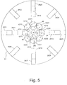
- eine Ansicht auf eine Anordnung von Strahlablenkelementen, die Teil der in der
Figur 4 gezeigten Messvorrichtung ist. - Zur Erläuterung der Funktionsweise der erfindungsgemäßen Messvorrichtung wird zunächst auf die
Figur 1 Bezug genommen, in der eine Messvorrichtung gemäß dem Stand der Technik in einem schematischen Meridionalschnitt gezeigt und insgesamt mit 10' bezeichnet ist. - Die Messvorrichtung 10' ist dafür vorgesehen, die Modulationsübertragungsfunktion (MTF) eines im Folgenden als Prüfling 12' bezeichneten optischen Systems zu messen. Der Prüfling 12' ist hier nur als einzelne Linse angedeutet; häufig wird es sich um ein optisches System mit mehreren refraktiven und/oder reflektiven optischen Elementen handeln.
- Die Modulationsübertragungsfunktion stellt ein wichtiges Hilfsmittel dar, um die Abbildungsqualität von optischen Systemen quantitativ zu bewerten, und beschreibt die Auflösungsleistung eines optischen Systems durch das Verhältnis des relativen Bildkontrasts zum relativen Objektkontrast. Wenn ein Objekt von einem optischen System abgebildet wird, kommt es durch Abbildungsfehler und Beugungserscheinungen zwangsläufig zu einer Qualitätsverringerung in der Bildebene. Auch Fertigungsabweichungen sowie Montage- und Ausrichtungsfehler schwächen die Abbildungsleistung des Prüflings 12'.
- Zur Messung Modulationsübertragungsfunktion bildet der Prüfling 12' ein Objekt; aus dem Bild des Objekts kann auf die Modulationsübertragungsfunktion des Prüflings 12' geschlossen werden. Das von dem Prüfling 12' abgebildete Objekt wird durch ein Lichtmuster gebildet, das von einer Lichtmustererzeugungseinrichtung 14' erzeugt wird. Die Lichtmustererzeugungseinrichtung 14' weist eine Blende 16' auf, die mehrere Blendenöffnungen 18' hat. Die
Figur 2 zeigt eine Draufsicht auf die Blende 16', in der die Anordnung der Blendenöffnungen 18' erkennbar ist. Die Blendenöffnungen 18' haben hier die Form von Kreuzschlitzen, die in einer regelmäßigen Anordnung über die Blende 16' verteilt sind. Der Abstand der äußeren Blendenöffnungen 18' von der Blendenmitte ist hier identisch. Die Blende 16' wird von einer als Glühbirne dargestellten Lichtquelle 20' mit Hilfe eines Kondensor 22' gleichmäßig ausgeleuchtet. - Der Prüfling 12' wird so in der Messvorrichtung 10' angeordnet, dass seine optische Achse mit einer Referenzachse 24' der Messvorrichtung 10' fluchtet. Die Referenzachse 24' der Vorrichtung 10' fällt dabei mit der optischen Achse des Kondensors 22' zusammen. Außerdem wird der Prüfling 12' axial so positioniert, dass die Blende 16' in der Brennebene 26' des Prüflings 12' angeordnet ist. Dadurch wird das durch die Blendenöffnungen 18' definierte Lichtmuster vom Prüfling 12' ins Unendliche abgebildet.
- Auf der der Lichtmustererzeugungseinrichtung 14' gegenüberliegenden Seite des Prüflings 12' sind zwei identisch aufgebaute Kameras 280', 281' angeordnet. Die Kameras 280', 281' enthalten jeweils ein Objektiv 30' und einen ortsauflösenden Lichtsensor 32', der sich in einer Brennebene des Objektivs 30' befindet. Auf dem Lichtsensor 32' entsteht dadurch jeweils ein Ausschnitt aus dem von der Lichtmustererzeugungseinrichtung 14' erzeugten Lichtmuster. Der Ausschnitt wird dabei u. a. durch die Anordnung der Kameras 280', 281' bezüglich der Referenzachse 24' festgelegt. Die Kamera 280', deren optische Achse 340' mit der Referenzachse 24' fluchtet, erfasst ein Bild der Blendenöffnung 18' in der Mitte der Blende 16' .
- Die optische Achse 341' der anderen Kamera 281' ist geneigt zur Referenzachse 24' angeordnet. Dadurch erfasst die Kamera 281' das Bild einer der äußeren Blendenöffnungen 18'.
- Um die zentrale Kamera 280' herum sind noch drei weitere Kameras angeordnet, die in der
Figur 1 aus Gründen der Übersicht nicht dargestellt sind. Diese drei weiteren Kameras erfassen die Bilder der drei anderen äußeren Blendenöffnungen 18'. Durch Auswertung der auf den Lichtsensoren 32' der Kameras 280', 281' entstehenden Bilder der Blendenöffnungen 18' kann die Modulationsübertragungsfunktion des Prüflings 12' in an sich bekannter Weise bestimmt werden. Mit der in denFiguren 1 und 2 dargestellten bekannten Messvorrichtung 10' lässt sich die Modulationsübertragungsfunktion an fünf unterschiedliche Feldpositionen messen. - Für Feldpositionen zwischen den fünf Blendenöffnungen 18' lässt sich jedoch keine Aussage über die Modulationsübertragungsfunktion treffen. Im Allgemeinen ist es deswegen wünschenswert, wenn die Modulationsübertragungsfunktion an möglichst vielen unterschiedlichen Feldpositionen unabhängig gemessen werden kann.
- Aus der
Figur 1 wird allerdings deutlich, dass bereits bei fünf zu vermessenden Feldpositionen die beiden dargestellten Kameras 280', 281' und die drei weiteren nicht dargestellten Kameras sehr dicht zueinander angeordnet sein müssen. Für eine Messung an z.B. 13 Feldpositionen, etwa unter Verwendung der in derFigur 3 gezeigten Blende 16, müssten somit 13 Kameras um die Referenzachse 24' herum angeordnet sein. Da die Kameras nicht beliebig miniaturisierbar sind, lässt sich die Modulationsübertragungsfunktion mit dem herkömmlichen Aufbau die Messvorrichtung 10' an derart vielen Feldpositionen nicht vermessen. - Die
Figur 4 zeigt eine erfindungsgemäße Messvorrichtung 10 in einem an dieFigur 1 angelehnten meridionalen Schnitt, mit der eine Messung auch an 13 oder mehr Feldpositionen möglich ist. Teile, die in gleicher oder ähnlicher Weise auch in der bekannten Messvorrichtung 10' enthalten sind, sind mit der gleichen Bezugsziffer, jedoch ohne Apostroph bezeichnet und werden nicht nochmals im Einzelnen erläutert. - Um jede der in der
Figur 3 gezeigten N = 13 Blendenöffnungen 18 getrennt voneinander auf jeweils einen Bildsensor 33 abbilden zu können, weist die erfindungsgemäße Messvorrichtung 10 eine entsprechende Zahl von N = 13 Kameras auf, die zum größten Teil in zwei unterschiedlichen Ebenen angeordnet sind. - In dem meridionalen Schnitt der
Figur 4 sind von den N = 13 Kameras 5 Kameras 280, 2811, 2813, 2821 und 2825 dargestellt. Die Kameras haben den gleichen Aufbau wie die in derFigur 1 gezeigten Kameras 280', 281' und umfassen somit jeweils ein Objektiv 30 und einen ortsauflösenden Lichtsensor 32, der in der Brennebene des Objektivs 30 angeordnet ist. - Die in der
Figur 4 oben erkennbaren Kameras 2811 und 2813 sind an einer ersten Montageplatte 40 befestigt, die senkrecht zur Referenzachse 24 der Messvorrichtung 10 angeordnet ist. Die erste Montageplatte 40 hat eine zentrale Öffnung 42, durch die hindurch sich die vertikal ausgerichtete Kamera 280 erstreckt. Mit der Kamera 280 lässt sich die Modulationsübertragungsfunktion für die axiale Feldposition messen. - Die Kameras 2811, 2813 sind horizontal ausgerichtet, so dass ihre optischen Achsen 3411 bzw. 3413 koplanar und senkrecht zur Referenzachse 24 angeordnet sind. Um schräg zur Referenzachse 24 verlaufende kollimierte Lichtbündel 271 auf die Kameras 2811 bzw. 2813 zu richten, sind an der ersten Montageplattform 40 außerdem plane Umlenkspiegel 4211 bzw. 4213 befestigt, welche die Lichtbündel 271 um einen Winkel α1 in der Meridionalebene umlenken.
- Unterhalb der Kameras 2811, 2813 erstreckt sich eine zweite Montageplatte 44, an der die übrigen Kameras befestigt sind. Die zweite Montageplatte 44 hat eine größere zentrale Öffnung 46, deren Durchmesser so bemessen ist, dass die geneigten Lichtbündel 271 hindurch treten und auf die Umlenkspiegel 4211, 4213 treffen können.
- An der zweiten Montageplatte 44 sind insgesamt 8 Kameras befestigt, von denen lediglich die in dem Meridionalschnitt angeordneten Kameras 2821 und 2825 dargestellt sind. Deren optische Achsen 3421 und 3425 verlaufen ebenfalls koplanar in einer zweiten Ebene, die sich parallel zu der ersten Ebene erstreckt. Um die stärker gegenüber der Referenzachse 24 geneigten Lichtbündel 272 in die Kameras 2821, 2825 zu richten, sind an der zweiten Montageplatte 44 weitere Umlenkspiegel 4221, 4225 befestigt, die eine Strahlumlenkung um einen Winkel α2 < α1 bewirken.
- Die
Figur 5 zeigt eine Ansicht auf die Anordnung der N = 13 Kameras in Lichtausbreitungsrichtung, d.h. in derFigur 4 von unten. In dieser Darstellung ist die Anordnung der acht Kameras 2821 bis 2828 auf der zweiten Montageplatte 44 erkennbar. Die Kameras 2821 bis 2828 sind winkelmäßig äquidistant um die Referenzachse 24 herum verteilt angeordnet, so dass der Winkel zwischen den optischen Achsen zweier benachbarter Kameras 2821 bis 2828 stets 45° beträgt. Entsprechend sind auch die den Kameras zugeordneten acht Umlenkspiegel 4221 bis 4228 winkelmäßig äquidistant um die Referenzachse 24 herum verteilt angeordnet. - Durch die Öffnung 46 in der zweiten Montageplatte 44 hindurch kann man die Anordnung der vier Umlenkspiegel 4111 bis 4114 erkennen, die den in der
Figur 5 gestrichelt angedeuteten Kameras 2821 bis 2824 zugeordnet sind. - Wie aus den
Figuren 4 und5 hervorgeht, ist es mit Hilfe der 12 Umlenkspiegel 4111 bis 4114 sowie 4221 bis 4228 möglich, die N = 13 Kameras 280, 2811 bis 2814 sowie 2821 bis 2825 weiter weg von der Referenzachse 24 anzuordnen. Dies ist Folge davon, dass die Umlenkspiegel 4111 bis 4114 sowie 4221 bis 4228 das auf die Kameras 2811 bis 2814 sowie 2821 bis 2825 auftreffende Licht von der Referenzachse 24 weg ablenken. Die Umlenkspiegel 4111 bis 4114 sowie 4221 bis 4228 benötigen keine Gehäuse und können so dimensioniert sein, dass ihre Fläche praktisch vollständig von den geneigten Lichtbündeln 271, 272 ausgeleuchtet wird. Dadurch können die Umlenkspiegel 4111 bis 4114 sowie 4221 bis 4228 sehr viel dichter zueinander angeordnet werden, als dies mit Kameras der Fall wäre. - Wie die
Figur 5 zeigt, ist es auch mit den Umlenkspiegeln 4111 bis 4114 sowie 4221 bis 4228 nicht möglich, die Zahl der Kameras - und dadurch die Zahl der unabhängig voneinander messbaren Feldpositionen - beliebig zu erhöhen. Wenn die Zahl der unabhängig voneinander messbaren Feldpositionen größer als 13 sein soll, müssen entweder die Umlenkspiegel kleiner oder weitere Umlenkspiegel in einer dritten Ebene angeordnet sein, was z. B. durch einen größeren Abstand zwischen dem Prüfling 12 und der.Anordnung der Kameras möglich wird.
Claims (8)
- Vorrichtung (10) zur Messung einer Abbildungseigenschaft eines optischen Systems (12), mit:a) einer Lichtmustererzeugungseinrichtung (14), die dazu eingerichtet ist, in einer Brennebene (26) des optischen Systems (12) ein Lichtmuster zu erzeugen,b) einer Referenzachse (24), an der die optische Achse des optischen Systems (12) ausrichtbar ist,c) einer Anordnung von N voneinander getrennten Kameras (280; 2811 bis 2814, 2821 bis 2828), wobeigekennzeichnet durch- jede Kamera ein Objektiv (30) und einen Lichtsensor (32) aufweist, der in einer Brennebene des Objektivs angeordnet ist, und wobei- die Kameras derart auf einer der Lichtmustererzeugungseinrichtung (14) gegenüberliegenden Seite angeordneten sind, dass jede Kamera mit ihrem Lichtsensor das unter der Mitwirkung des optischen Systems entstandene Bild von genau einem Ausschnitt des Lichtmusters erfasst,
mindestens ein Strahlablenkelement (4211 bis 4214, 4221 bis 4228), das derart zwischen dem optischen System und mindestens einer der Kameras (2811 bis 2814, 2821 bis 2828) angeordnet ist, dass es das auf die mindestens eine Kamera auftreffende Licht (271, 272) von der Referenzachse (24) weg ablenkt. - Vorrichtung nach Anspruch 1, dadurch gekennzeichnet, dass die optische Achse (3411 bis 3414, 3421 bis 3428) mindestens einer Kamera senkrecht zu der Referenzachse (24) angeordnet ist.
- Vorrichtung nach Anspruch 1 oder 2, dadurch gekennzeichnet, dass N > 4 ist und mindestens vier erste Kameras (2811 bis 2814) in einer ersten Ebene angeordnet sind.
- Vorrichtung nach Anspruch 3, dadurch gekennzeichnet, dass N > 9 ist und mindestens vier zweite Kameras (2821 bis 2818) in einer zweiten Ebene angeordnet sind, die parallel zu der ersten Ebene verläuft.
- Vorrichtung nach Anspruch 4, dadurch gekennzeichnet, dass die Strahlablenkelemente (4211 bis 4214) das Licht (271), das auf die ersten Kameras (2811 bis 2814) fällt, weniger ablenken als das Licht (272), das auf die zweiten Kameras (2821 bis 2828) fällt.
- Vorrichtung nach Anspruch 5, dadurch gekennzeichnet, dass die ersten Kameras (2811 bis 2814) und die zweiten Kameras (2821 bis 2828) und die Strahlablenkelemente (4211 bis 4214, 4221 bis 4228) so angeordnet sind, dass Licht (271), das unter einem Winkel α1 bezüglich der Referenzachse (24) aus dem optischen System (12) austritt, von den Strahlablenkelementen (4211 bis 4214) stärker abgelenkt und auf die ersten Kameras (2811 bis 2814) gerichtet wird, und dass Licht (272), das unter einem Winkel α2 > α1 bezüglich der Referenzachse (24) aus dem optischen System (12) austritt, weniger stark abgelenkt und auf die zweiten Kameras (2821 bis 2828) gerichtet wird, wobei die erste Ebene weiter entfernt von dem optischen System (12) angeordnet ist als die zweite Ebene.
- Vorrichtung nach einem der Ansprüche 3 bis 6, dadurch gekennzeichnet, dass in einer Ebene angeordnete Kameras und die diesen zugeordneten Strahlablenkelemente an einer gemeinsamen Tragstruktur (40, 44) befestigt sind.
- Vorrichtung nach Anspruch 7, dadurch gekennzeichnet, dass die Tragstruktur eine ringförmige Montageplatte (40, 44) aufweist.
Applications Claiming Priority (2)
| Application Number | Priority Date | Filing Date | Title |
|---|---|---|---|
| DE102015006015.5A DE102015006015A1 (de) | 2015-05-13 | 2015-05-13 | Vorrichtung zur Messung einer Abbildungseigenschaft eines optischen Systems |
| PCT/EP2016/000749 WO2016180525A1 (de) | 2015-05-13 | 2016-05-07 | Vorrichtung zur messung einer abbildungseigenschaft eines optischen systems |
Publications (2)
| Publication Number | Publication Date |
|---|---|
| EP3295144A1 EP3295144A1 (de) | 2018-03-21 |
| EP3295144B1 true EP3295144B1 (de) | 2020-07-22 |
Family
ID=55963287
Family Applications (1)
| Application Number | Title | Priority Date | Filing Date |
|---|---|---|---|
| EP16721642.3A Active EP3295144B1 (de) | 2015-05-13 | 2016-05-07 | Vorrichtung zur messung einer abbildungseigenschaft eines optischen systems |
Country Status (4)
| Country | Link |
|---|---|
| US (1) | US10386267B2 (de) |
| EP (1) | EP3295144B1 (de) |
| DE (1) | DE102015006015A1 (de) |
| WO (1) | WO2016180525A1 (de) |
Cited By (1)
| Publication number | Priority date | Publication date | Assignee | Title |
|---|---|---|---|---|
| JP7285894B2 (ja) | 2020-09-25 | 2023-06-02 | トライオプティクス ゲーエムベーハー | Mtf測定装置とその使用 |
Families Citing this family (4)
| Publication number | Priority date | Publication date | Assignee | Title |
|---|---|---|---|---|
| CN110186651B (zh) * | 2018-02-23 | 2021-08-03 | 宁波舜宇车载光学技术有限公司 | 用于镜头的mtf测试设备 |
| KR20220030515A (ko) * | 2020-09-02 | 2022-03-11 | 삼성디스플레이 주식회사 | 해상력 측정 장치 및 그것을 이용한 해상력 측정 방법 |
| DE102021102246A1 (de) | 2021-02-01 | 2022-08-04 | Trioptics Gmbh | Vorrichtung und Verfahren zum Messen einer optischen Eigenschaft eines optischen Systems |
| DE102021105027A1 (de) | 2021-03-02 | 2022-09-08 | Trioptics Gmbh | Vorrichtung und Verfahren zum Messen von Abbildungseigenschaften eines optischen Systems |
Family Cites Families (10)
| Publication number | Priority date | Publication date | Assignee | Title |
|---|---|---|---|---|
| JPS5885132A (ja) * | 1981-11-16 | 1983-05-21 | Ricoh Co Ltd | レンズのmtf測定装置 |
| JPS6129732A (ja) * | 1984-07-20 | 1986-02-10 | Olympus Optical Co Ltd | Mtf測定装置 |
| DE3620129A1 (de) * | 1986-06-14 | 1987-12-17 | Zeiss Carl Fa | Vorrichtung zum pruefen von bauteilen aus transparentem material auf oberflaechenfehler und einschluesse |
| DE4003144A1 (de) * | 1990-02-02 | 1991-08-08 | Rodenstock Instr | Einrichtung zum messen von refraktionseigenschaften optischer systeme |
| US5801822A (en) * | 1997-02-06 | 1998-09-01 | Pbh, Inc. | Ophthalmic lens inspection system |
| DE10339473A1 (de) | 2003-08-27 | 2005-03-24 | Seidenader Maschinenbau Gmbh | Vorrichtung zur Prüfung von Erzeugnissen |
| TWI391644B (zh) * | 2008-12-31 | 2013-04-01 | Uma Technology Inc | 鏡頭檢測裝置及方法 |
| DE102010014215A1 (de) * | 2010-04-08 | 2011-10-13 | Chrosziel Gmbh | Verfahren und System zum Bestimmen von optischen Eigenschaften eines Linsensystems |
| TWI468658B (zh) * | 2011-12-21 | 2015-01-11 | Uma Technology Inc | 鏡頭檢測裝置及方法 |
| MY187200A (en) * | 2013-10-08 | 2021-09-09 | Emage Vision Pte Ltd | System and method for inspection of wet ophthalmic lens |
-
2015
- 2015-05-13 DE DE102015006015.5A patent/DE102015006015A1/de not_active Withdrawn
-
2016
- 2016-05-07 EP EP16721642.3A patent/EP3295144B1/de active Active
- 2016-05-07 WO PCT/EP2016/000749 patent/WO2016180525A1/de not_active Ceased
- 2016-05-07 US US15/573,434 patent/US10386267B2/en active Active
Non-Patent Citations (1)
| Title |
|---|
| None * |
Cited By (1)
| Publication number | Priority date | Publication date | Assignee | Title |
|---|---|---|---|---|
| JP7285894B2 (ja) | 2020-09-25 | 2023-06-02 | トライオプティクス ゲーエムベーハー | Mtf測定装置とその使用 |
Also Published As
| Publication number | Publication date |
|---|---|
| DE102015006015A1 (de) | 2016-11-17 |
| WO2016180525A1 (de) | 2016-11-17 |
| US20180136079A1 (en) | 2018-05-17 |
| EP3295144A1 (de) | 2018-03-21 |
| US10386267B2 (en) | 2019-08-20 |
Similar Documents
| Publication | Publication Date | Title |
|---|---|---|
| EP2507662B1 (de) | Vorrichtung zur optischen abbildung | |
| EP2430491B1 (de) | Vorrichtung zur formung von laserstrahlung sowie laservorrichtung mit einer derartigen vorrichtung | |
| WO2016180525A1 (de) | Vorrichtung zur messung einer abbildungseigenschaft eines optischen systems | |
| EP3596506B1 (de) | Optische abstrahlvorrichtung für laserpulse mit selektiver optik | |
| DE102013102553A1 (de) | Vorrichtung zur Homogenisierung von Laserstrahlung | |
| EP1845349A1 (de) | Spektralanalytische Einheit mit einem Beugungsgitter | |
| EP1677070B1 (de) | Verfahren und Vorrichtung zum Bestimmen der Durchbiegung eines Verbindungselements | |
| WO2006072263A1 (de) | Vorrichtung zur homogenisierung von licht | |
| DE69803044T2 (de) | Optisches gerät zur kontaktlosen messung des abstandes zu einer lichtquelle | |
| EP0257188A1 (de) | Ortsauflösender Sensor zur Erfassung einzelner Lichtblitze | |
| DE10317736A1 (de) | Abtasteinheit für eine Positionsmesseinrichtung zum optischen Abtasten einer Maßverkörperung | |
| DE10323088A1 (de) | Positionsmesseinrichtung | |
| DE102006058057B3 (de) | Verfahren und Vorrichtung zur optischen Erfassung einer Struktur | |
| DE10159234A1 (de) | Vorrichtung zur Untersuchung von Dokumenten | |
| DE102023107515B4 (de) | Vorrichtung und Verfahren zur Erfassung mindestens eines Tropfens | |
| EP4067931B1 (de) | Optoelektronischer sensor und verfahren zur erfassung eines objekts | |
| DE102015100695B4 (de) | Optische Anordnung für ein Laser-Scanner-System | |
| DE102004020881A1 (de) | Verfahren und Vorrichtung zum geometrischen Kalibrieren von optoelektronischen Messbildkameras | |
| DE102021202164B3 (de) | Tandemblendenarchitektur zur Füllfaktorerhöhung von kompakten Multikanalabbildungssystemen | |
| DE102018113136B4 (de) | Kameramodul und Kamerasystem mit einem Kameramodul | |
| EP4285091A1 (de) | Vorrichtung und verfahren zum messen einer optischen eigenschaft eines optischen systems | |
| EP3835727A1 (de) | Optische positionsmesseinrichtung | |
| DE102007039988B4 (de) | Mikroskop | |
| EP2335029B1 (de) | Optische positionsmesseinrichtung | |
| WO2009036926A1 (de) | Optische vorrichtung |
Legal Events
| Date | Code | Title | Description |
|---|---|---|---|
| STAA | Information on the status of an ep patent application or granted ep patent |
Free format text: STATUS: THE INTERNATIONAL PUBLICATION HAS BEEN MADE |
|
| PUAI | Public reference made under article 153(3) epc to a published international application that has entered the european phase |
Free format text: ORIGINAL CODE: 0009012 |
|
| STAA | Information on the status of an ep patent application or granted ep patent |
Free format text: STATUS: REQUEST FOR EXAMINATION WAS MADE |
|
| 17P | Request for examination filed |
Effective date: 20171011 |
|
| AK | Designated contracting states |
Kind code of ref document: A1 Designated state(s): AL AT BE BG CH CY CZ DE DK EE ES FI FR GB GR HR HU IE IS IT LI LT LU LV MC MK MT NL NO PL PT RO RS SE SI SK SM TR |
|
| AX | Request for extension of the european patent |
Extension state: BA ME |
|
| DAV | Request for validation of the european patent (deleted) | ||
| DAX | Request for extension of the european patent (deleted) | ||
| RAP1 | Party data changed (applicant data changed or rights of an application transferred) |
Owner name: TRIOPTICS GMBH |
|
| GRAP | Despatch of communication of intention to grant a patent |
Free format text: ORIGINAL CODE: EPIDOSNIGR1 |
|
| STAA | Information on the status of an ep patent application or granted ep patent |
Free format text: STATUS: GRANT OF PATENT IS INTENDED |
|
| INTG | Intention to grant announced |
Effective date: 20200108 |
|
| GRAS | Grant fee paid |
Free format text: ORIGINAL CODE: EPIDOSNIGR3 |
|
| GRAA | (expected) grant |
Free format text: ORIGINAL CODE: 0009210 |
|
| STAA | Information on the status of an ep patent application or granted ep patent |
Free format text: STATUS: THE PATENT HAS BEEN GRANTED |
|
| AK | Designated contracting states |
Kind code of ref document: B1 Designated state(s): AL AT BE BG CH CY CZ DE DK EE ES FI FR GB GR HR HU IE IS IT LI LT LU LV MC MK MT NL NO PL PT RO RS SE SI SK SM TR |
|
| REG | Reference to a national code |
Ref country code: GB Ref legal event code: FG4D Free format text: NOT ENGLISH |
|
| REG | Reference to a national code |
Ref country code: CH Ref legal event code: EP |
|
| REG | Reference to a national code |
Ref country code: DE Ref legal event code: R096 Ref document number: 502016010585 Country of ref document: DE |
|
| REG | Reference to a national code |
Ref country code: AT Ref legal event code: REF Ref document number: 1293853 Country of ref document: AT Kind code of ref document: T Effective date: 20200815 |
|
| REG | Reference to a national code |
Ref country code: IE Ref legal event code: FG4D Free format text: LANGUAGE OF EP DOCUMENT: GERMAN |
|
| REG | Reference to a national code |
Ref country code: LT Ref legal event code: MG4D |
|
| PG25 | Lapsed in a contracting state [announced via postgrant information from national office to epo] |
Ref country code: FI Free format text: LAPSE BECAUSE OF FAILURE TO SUBMIT A TRANSLATION OF THE DESCRIPTION OR TO PAY THE FEE WITHIN THE PRESCRIBED TIME-LIMIT Effective date: 20200722 Ref country code: SE Free format text: LAPSE BECAUSE OF FAILURE TO SUBMIT A TRANSLATION OF THE DESCRIPTION OR TO PAY THE FEE WITHIN THE PRESCRIBED TIME-LIMIT Effective date: 20200722 Ref country code: PT Free format text: LAPSE BECAUSE OF FAILURE TO SUBMIT A TRANSLATION OF THE DESCRIPTION OR TO PAY THE FEE WITHIN THE PRESCRIBED TIME-LIMIT Effective date: 20201123 Ref country code: BG Free format text: LAPSE BECAUSE OF FAILURE TO SUBMIT A TRANSLATION OF THE DESCRIPTION OR TO PAY THE FEE WITHIN THE PRESCRIBED TIME-LIMIT Effective date: 20201022 Ref country code: NO Free format text: LAPSE BECAUSE OF FAILURE TO SUBMIT A TRANSLATION OF THE DESCRIPTION OR TO PAY THE FEE WITHIN THE PRESCRIBED TIME-LIMIT Effective date: 20201022 Ref country code: GR Free format text: LAPSE BECAUSE OF FAILURE TO SUBMIT A TRANSLATION OF THE DESCRIPTION OR TO PAY THE FEE WITHIN THE PRESCRIBED TIME-LIMIT Effective date: 20201023 Ref country code: LT Free format text: LAPSE BECAUSE OF FAILURE TO SUBMIT A TRANSLATION OF THE DESCRIPTION OR TO PAY THE FEE WITHIN THE PRESCRIBED TIME-LIMIT Effective date: 20200722 Ref country code: ES Free format text: LAPSE BECAUSE OF FAILURE TO SUBMIT A TRANSLATION OF THE DESCRIPTION OR TO PAY THE FEE WITHIN THE PRESCRIBED TIME-LIMIT Effective date: 20200722 Ref country code: HR Free format text: LAPSE BECAUSE OF FAILURE TO SUBMIT A TRANSLATION OF THE DESCRIPTION OR TO PAY THE FEE WITHIN THE PRESCRIBED TIME-LIMIT Effective date: 20200722 |
|
| PG25 | Lapsed in a contracting state [announced via postgrant information from national office to epo] |
Ref country code: RS Free format text: LAPSE BECAUSE OF FAILURE TO SUBMIT A TRANSLATION OF THE DESCRIPTION OR TO PAY THE FEE WITHIN THE PRESCRIBED TIME-LIMIT Effective date: 20200722 Ref country code: LV Free format text: LAPSE BECAUSE OF FAILURE TO SUBMIT A TRANSLATION OF THE DESCRIPTION OR TO PAY THE FEE WITHIN THE PRESCRIBED TIME-LIMIT Effective date: 20200722 Ref country code: PL Free format text: LAPSE BECAUSE OF FAILURE TO SUBMIT A TRANSLATION OF THE DESCRIPTION OR TO PAY THE FEE WITHIN THE PRESCRIBED TIME-LIMIT Effective date: 20200722 Ref country code: IS Free format text: LAPSE BECAUSE OF FAILURE TO SUBMIT A TRANSLATION OF THE DESCRIPTION OR TO PAY THE FEE WITHIN THE PRESCRIBED TIME-LIMIT Effective date: 20201122 |
|
| PG25 | Lapsed in a contracting state [announced via postgrant information from national office to epo] |
Ref country code: NL Free format text: LAPSE BECAUSE OF FAILURE TO SUBMIT A TRANSLATION OF THE DESCRIPTION OR TO PAY THE FEE WITHIN THE PRESCRIBED TIME-LIMIT Effective date: 20200722 |
|
| REG | Reference to a national code |
Ref country code: DE Ref legal event code: R097 Ref document number: 502016010585 Country of ref document: DE |
|
| PG25 | Lapsed in a contracting state [announced via postgrant information from national office to epo] |
Ref country code: IT Free format text: LAPSE BECAUSE OF FAILURE TO SUBMIT A TRANSLATION OF THE DESCRIPTION OR TO PAY THE FEE WITHIN THE PRESCRIBED TIME-LIMIT Effective date: 20200722 Ref country code: EE Free format text: LAPSE BECAUSE OF FAILURE TO SUBMIT A TRANSLATION OF THE DESCRIPTION OR TO PAY THE FEE WITHIN THE PRESCRIBED TIME-LIMIT Effective date: 20200722 Ref country code: RO Free format text: LAPSE BECAUSE OF FAILURE TO SUBMIT A TRANSLATION OF THE DESCRIPTION OR TO PAY THE FEE WITHIN THE PRESCRIBED TIME-LIMIT Effective date: 20200722 Ref country code: SM Free format text: LAPSE BECAUSE OF FAILURE TO SUBMIT A TRANSLATION OF THE DESCRIPTION OR TO PAY THE FEE WITHIN THE PRESCRIBED TIME-LIMIT Effective date: 20200722 Ref country code: DK Free format text: LAPSE BECAUSE OF FAILURE TO SUBMIT A TRANSLATION OF THE DESCRIPTION OR TO PAY THE FEE WITHIN THE PRESCRIBED TIME-LIMIT Effective date: 20200722 |
|
| PLBE | No opposition filed within time limit |
Free format text: ORIGINAL CODE: 0009261 |
|
| STAA | Information on the status of an ep patent application or granted ep patent |
Free format text: STATUS: NO OPPOSITION FILED WITHIN TIME LIMIT |
|
| PG25 | Lapsed in a contracting state [announced via postgrant information from national office to epo] |
Ref country code: AL Free format text: LAPSE BECAUSE OF FAILURE TO SUBMIT A TRANSLATION OF THE DESCRIPTION OR TO PAY THE FEE WITHIN THE PRESCRIBED TIME-LIMIT Effective date: 20200722 |
|
| 26N | No opposition filed |
Effective date: 20210423 |
|
| PG25 | Lapsed in a contracting state [announced via postgrant information from national office to epo] |
Ref country code: SK Free format text: LAPSE BECAUSE OF FAILURE TO SUBMIT A TRANSLATION OF THE DESCRIPTION OR TO PAY THE FEE WITHIN THE PRESCRIBED TIME-LIMIT Effective date: 20200722 |
|
| PG25 | Lapsed in a contracting state [announced via postgrant information from national office to epo] |
Ref country code: SI Free format text: LAPSE BECAUSE OF FAILURE TO SUBMIT A TRANSLATION OF THE DESCRIPTION OR TO PAY THE FEE WITHIN THE PRESCRIBED TIME-LIMIT Effective date: 20200722 |
|
| REG | Reference to a national code |
Ref country code: NL Ref legal event code: MP Effective date: 20200722 |
|
| REG | Reference to a national code |
Ref country code: CH Ref legal event code: PL |
|
| GBPC | Gb: european patent ceased through non-payment of renewal fee |
Effective date: 20210507 |
|
| PG25 | Lapsed in a contracting state [announced via postgrant information from national office to epo] |
Ref country code: LI Free format text: LAPSE BECAUSE OF NON-PAYMENT OF DUE FEES Effective date: 20210531 Ref country code: MC Free format text: LAPSE BECAUSE OF FAILURE TO SUBMIT A TRANSLATION OF THE DESCRIPTION OR TO PAY THE FEE WITHIN THE PRESCRIBED TIME-LIMIT Effective date: 20200722 Ref country code: LU Free format text: LAPSE BECAUSE OF NON-PAYMENT OF DUE FEES Effective date: 20210507 Ref country code: CH Free format text: LAPSE BECAUSE OF NON-PAYMENT OF DUE FEES Effective date: 20210531 |
|
| REG | Reference to a national code |
Ref country code: BE Ref legal event code: MM Effective date: 20210531 |
|
| PG25 | Lapsed in a contracting state [announced via postgrant information from national office to epo] |
Ref country code: IE Free format text: LAPSE BECAUSE OF NON-PAYMENT OF DUE FEES Effective date: 20210507 Ref country code: GB Free format text: LAPSE BECAUSE OF NON-PAYMENT OF DUE FEES Effective date: 20210507 |
|
| PG25 | Lapsed in a contracting state [announced via postgrant information from national office to epo] |
Ref country code: FR Free format text: LAPSE BECAUSE OF NON-PAYMENT OF DUE FEES Effective date: 20210531 |
|
| REG | Reference to a national code |
Ref country code: AT Ref legal event code: MM01 Ref document number: 1293853 Country of ref document: AT Kind code of ref document: T Effective date: 20210507 |
|
| PG25 | Lapsed in a contracting state [announced via postgrant information from national office to epo] |
Ref country code: BE Free format text: LAPSE BECAUSE OF NON-PAYMENT OF DUE FEES Effective date: 20210531 |
|
| REG | Reference to a national code |
Ref country code: DE Ref legal event code: R082 Ref document number: 502016010585 Country of ref document: DE Representative=s name: WALDAUF, ALEXANDER, DIPL.-ING. DR.-ING., DE |
|
| PG25 | Lapsed in a contracting state [announced via postgrant information from national office to epo] |
Ref country code: AT Free format text: LAPSE BECAUSE OF NON-PAYMENT OF DUE FEES Effective date: 20210507 |
|
| PG25 | Lapsed in a contracting state [announced via postgrant information from national office to epo] |
Ref country code: HU Free format text: LAPSE BECAUSE OF FAILURE TO SUBMIT A TRANSLATION OF THE DESCRIPTION OR TO PAY THE FEE WITHIN THE PRESCRIBED TIME-LIMIT; INVALID AB INITIO Effective date: 20160507 |
|
| PG25 | Lapsed in a contracting state [announced via postgrant information from national office to epo] |
Ref country code: CY Free format text: LAPSE BECAUSE OF FAILURE TO SUBMIT A TRANSLATION OF THE DESCRIPTION OR TO PAY THE FEE WITHIN THE PRESCRIBED TIME-LIMIT Effective date: 20200722 |
|
| PG25 | Lapsed in a contracting state [announced via postgrant information from national office to epo] |
Ref country code: MK Free format text: LAPSE BECAUSE OF FAILURE TO SUBMIT A TRANSLATION OF THE DESCRIPTION OR TO PAY THE FEE WITHIN THE PRESCRIBED TIME-LIMIT Effective date: 20200722 |
|
| PG25 | Lapsed in a contracting state [announced via postgrant information from national office to epo] |
Ref country code: TR Free format text: LAPSE BECAUSE OF FAILURE TO SUBMIT A TRANSLATION OF THE DESCRIPTION OR TO PAY THE FEE WITHIN THE PRESCRIBED TIME-LIMIT Effective date: 20200722 |
|
| PG25 | Lapsed in a contracting state [announced via postgrant information from national office to epo] |
Ref country code: MT Free format text: LAPSE BECAUSE OF FAILURE TO SUBMIT A TRANSLATION OF THE DESCRIPTION OR TO PAY THE FEE WITHIN THE PRESCRIBED TIME-LIMIT Effective date: 20200722 |
|
| PGFP | Annual fee paid to national office [announced via postgrant information from national office to epo] |
Ref country code: DE Payment date: 20250519 Year of fee payment: 10 |
|
| PGFP | Annual fee paid to national office [announced via postgrant information from national office to epo] |
Ref country code: CZ Payment date: 20250424 Year of fee payment: 10 |