EP3295067B1 - Ball valve with pressure relief feature - Google Patents
Ball valve with pressure relief feature Download PDFInfo
- Publication number
- EP3295067B1 EP3295067B1 EP15825695.8A EP15825695A EP3295067B1 EP 3295067 B1 EP3295067 B1 EP 3295067B1 EP 15825695 A EP15825695 A EP 15825695A EP 3295067 B1 EP3295067 B1 EP 3295067B1
- Authority
- EP
- European Patent Office
- Prior art keywords
- ball
- valve
- pressure relief
- valve assembly
- outlet
- Prior art date
- Legal status (The legal status is an assumption and is not a legal conclusion. Google has not performed a legal analysis and makes no representation as to the accuracy of the status listed.)
- Active
Links
- 230000037361 pathway Effects 0.000 claims description 82
- 239000012530 fluid Substances 0.000 claims description 40
- 238000002955 isolation Methods 0.000 description 33
- 239000003507 refrigerant Substances 0.000 description 11
- CURLTUGMZLYLDI-UHFFFAOYSA-N Carbon dioxide Chemical compound O=C=O CURLTUGMZLYLDI-UHFFFAOYSA-N 0.000 description 6
- 239000000463 material Substances 0.000 description 5
- 230000000712 assembly Effects 0.000 description 4
- 238000000429 assembly Methods 0.000 description 4
- 238000005057 refrigeration Methods 0.000 description 4
- 229910002092 carbon dioxide Inorganic materials 0.000 description 3
- 239000001569 carbon dioxide Substances 0.000 description 3
- 238000005219 brazing Methods 0.000 description 2
- 230000004048 modification Effects 0.000 description 2
- 238000012986 modification Methods 0.000 description 2
- 229910000831 Steel Inorganic materials 0.000 description 1
- 229920006362 Teflon® Polymers 0.000 description 1
- 230000001154 acute effect Effects 0.000 description 1
- 230000004075 alteration Effects 0.000 description 1
- 230000000740 bleeding effect Effects 0.000 description 1
- 230000000903 blocking effect Effects 0.000 description 1
- 230000008859 change Effects 0.000 description 1
- 230000007812 deficiency Effects 0.000 description 1
- 230000002950 deficient Effects 0.000 description 1
- 230000001419 dependent effect Effects 0.000 description 1
- 239000000203 mixture Substances 0.000 description 1
- 230000004044 response Effects 0.000 description 1
- 238000007789 sealing Methods 0.000 description 1
- 239000010959 steel Substances 0.000 description 1
Images


Classifications
-
- F—MECHANICAL ENGINEERING; LIGHTING; HEATING; WEAPONS; BLASTING
- F16—ENGINEERING ELEMENTS AND UNITS; GENERAL MEASURES FOR PRODUCING AND MAINTAINING EFFECTIVE FUNCTIONING OF MACHINES OR INSTALLATIONS; THERMAL INSULATION IN GENERAL
- F16K—VALVES; TAPS; COCKS; ACTUATING-FLOATS; DEVICES FOR VENTING OR AERATING
- F16K17/00—Safety valves; Equalising valves, e.g. pressure relief valves
- F16K17/02—Safety valves; Equalising valves, e.g. pressure relief valves opening on surplus pressure on one side; closing on insufficient pressure on one side
- F16K17/168—Safety valves; Equalising valves, e.g. pressure relief valves opening on surplus pressure on one side; closing on insufficient pressure on one side combined with manually-controlled valves, e.g. a valve combined with a safety valve
-
- F—MECHANICAL ENGINEERING; LIGHTING; HEATING; WEAPONS; BLASTING
- F16—ENGINEERING ELEMENTS AND UNITS; GENERAL MEASURES FOR PRODUCING AND MAINTAINING EFFECTIVE FUNCTIONING OF MACHINES OR INSTALLATIONS; THERMAL INSULATION IN GENERAL
- F16K—VALVES; TAPS; COCKS; ACTUATING-FLOATS; DEVICES FOR VENTING OR AERATING
- F16K11/00—Multiple-way valves, e.g. mixing valves; Pipe fittings incorporating such valves
- F16K11/02—Multiple-way valves, e.g. mixing valves; Pipe fittings incorporating such valves with all movable sealing faces moving as one unit
- F16K11/06—Multiple-way valves, e.g. mixing valves; Pipe fittings incorporating such valves with all movable sealing faces moving as one unit comprising only sliding valves, i.e. sliding closure elements
- F16K11/072—Multiple-way valves, e.g. mixing valves; Pipe fittings incorporating such valves with all movable sealing faces moving as one unit comprising only sliding valves, i.e. sliding closure elements with pivoted closure members
- F16K11/076—Multiple-way valves, e.g. mixing valves; Pipe fittings incorporating such valves with all movable sealing faces moving as one unit comprising only sliding valves, i.e. sliding closure elements with pivoted closure members with sealing faces shaped as surfaces of solids of revolution
-
- F—MECHANICAL ENGINEERING; LIGHTING; HEATING; WEAPONS; BLASTING
- F16—ENGINEERING ELEMENTS AND UNITS; GENERAL MEASURES FOR PRODUCING AND MAINTAINING EFFECTIVE FUNCTIONING OF MACHINES OR INSTALLATIONS; THERMAL INSULATION IN GENERAL
- F16K—VALVES; TAPS; COCKS; ACTUATING-FLOATS; DEVICES FOR VENTING OR AERATING
- F16K15/00—Check valves
- F16K15/02—Check valves with guided rigid valve members
- F16K15/04—Check valves with guided rigid valve members shaped as balls
- F16K15/044—Check valves with guided rigid valve members shaped as balls spring-loaded
- F16K15/046—Check valves with guided rigid valve members shaped as balls spring-loaded by a spring other than a helicoidal spring
-
- F—MECHANICAL ENGINEERING; LIGHTING; HEATING; WEAPONS; BLASTING
- F16—ENGINEERING ELEMENTS AND UNITS; GENERAL MEASURES FOR PRODUCING AND MAINTAINING EFFECTIVE FUNCTIONING OF MACHINES OR INSTALLATIONS; THERMAL INSULATION IN GENERAL
- F16K—VALVES; TAPS; COCKS; ACTUATING-FLOATS; DEVICES FOR VENTING OR AERATING
- F16K15/00—Check valves
- F16K15/02—Check valves with guided rigid valve members
- F16K15/04—Check valves with guided rigid valve members shaped as balls
- F16K15/048—Ball features
-
- F—MECHANICAL ENGINEERING; LIGHTING; HEATING; WEAPONS; BLASTING
- F16—ENGINEERING ELEMENTS AND UNITS; GENERAL MEASURES FOR PRODUCING AND MAINTAINING EFFECTIVE FUNCTIONING OF MACHINES OR INSTALLATIONS; THERMAL INSULATION IN GENERAL
- F16K—VALVES; TAPS; COCKS; ACTUATING-FLOATS; DEVICES FOR VENTING OR AERATING
- F16K15/00—Check valves
- F16K15/18—Check valves with actuating mechanism; Combined check valves and actuated valves
- F16K15/182—Check valves with actuating mechanism; Combined check valves and actuated valves with actuating mechanism
- F16K15/1823—Check valves with actuating mechanism; Combined check valves and actuated valves with actuating mechanism for ball check valves
-
- F—MECHANICAL ENGINEERING; LIGHTING; HEATING; WEAPONS; BLASTING
- F16—ENGINEERING ELEMENTS AND UNITS; GENERAL MEASURES FOR PRODUCING AND MAINTAINING EFFECTIVE FUNCTIONING OF MACHINES OR INSTALLATIONS; THERMAL INSULATION IN GENERAL
- F16K—VALVES; TAPS; COCKS; ACTUATING-FLOATS; DEVICES FOR VENTING OR AERATING
- F16K15/00—Check valves
- F16K15/18—Check valves with actuating mechanism; Combined check valves and actuated valves
- F16K15/184—Combined check valves and actuated valves
- F16K15/1848—Check valves combined with valves having a rotating tap or cock
-
- F—MECHANICAL ENGINEERING; LIGHTING; HEATING; WEAPONS; BLASTING
- F16—ENGINEERING ELEMENTS AND UNITS; GENERAL MEASURES FOR PRODUCING AND MAINTAINING EFFECTIVE FUNCTIONING OF MACHINES OR INSTALLATIONS; THERMAL INSULATION IN GENERAL
- F16K—VALVES; TAPS; COCKS; ACTUATING-FLOATS; DEVICES FOR VENTING OR AERATING
- F16K17/00—Safety valves; Equalising valves, e.g. pressure relief valves
- F16K17/02—Safety valves; Equalising valves, e.g. pressure relief valves opening on surplus pressure on one side; closing on insufficient pressure on one side
- F16K17/04—Safety valves; Equalising valves, e.g. pressure relief valves opening on surplus pressure on one side; closing on insufficient pressure on one side spring-loaded
- F16K17/0406—Safety valves; Equalising valves, e.g. pressure relief valves opening on surplus pressure on one side; closing on insufficient pressure on one side spring-loaded in the form of balls
-
- F—MECHANICAL ENGINEERING; LIGHTING; HEATING; WEAPONS; BLASTING
- F16—ENGINEERING ELEMENTS AND UNITS; GENERAL MEASURES FOR PRODUCING AND MAINTAINING EFFECTIVE FUNCTIONING OF MACHINES OR INSTALLATIONS; THERMAL INSULATION IN GENERAL
- F16K—VALVES; TAPS; COCKS; ACTUATING-FLOATS; DEVICES FOR VENTING OR AERATING
- F16K27/00—Construction of housing; Use of materials therefor
- F16K27/06—Construction of housing; Use of materials therefor of taps or cocks
- F16K27/067—Construction of housing; Use of materials therefor of taps or cocks with spherical plugs
-
- F—MECHANICAL ENGINEERING; LIGHTING; HEATING; WEAPONS; BLASTING
- F16—ENGINEERING ELEMENTS AND UNITS; GENERAL MEASURES FOR PRODUCING AND MAINTAINING EFFECTIVE FUNCTIONING OF MACHINES OR INSTALLATIONS; THERMAL INSULATION IN GENERAL
- F16K—VALVES; TAPS; COCKS; ACTUATING-FLOATS; DEVICES FOR VENTING OR AERATING
- F16K31/00—Actuating devices; Operating means; Releasing devices
- F16K31/12—Actuating devices; Operating means; Releasing devices actuated by fluid
- F16K31/122—Actuating devices; Operating means; Releasing devices actuated by fluid the fluid acting on a piston
- F16K31/1221—Actuating devices; Operating means; Releasing devices actuated by fluid the fluid acting on a piston one side of the piston being spring-loaded
-
- F—MECHANICAL ENGINEERING; LIGHTING; HEATING; WEAPONS; BLASTING
- F16—ENGINEERING ELEMENTS AND UNITS; GENERAL MEASURES FOR PRODUCING AND MAINTAINING EFFECTIVE FUNCTIONING OF MACHINES OR INSTALLATIONS; THERMAL INSULATION IN GENERAL
- F16K—VALVES; TAPS; COCKS; ACTUATING-FLOATS; DEVICES FOR VENTING OR AERATING
- F16K31/00—Actuating devices; Operating means; Releasing devices
- F16K31/44—Mechanical actuating means
-
- F—MECHANICAL ENGINEERING; LIGHTING; HEATING; WEAPONS; BLASTING
- F16—ENGINEERING ELEMENTS AND UNITS; GENERAL MEASURES FOR PRODUCING AND MAINTAINING EFFECTIVE FUNCTIONING OF MACHINES OR INSTALLATIONS; THERMAL INSULATION IN GENERAL
- F16K—VALVES; TAPS; COCKS; ACTUATING-FLOATS; DEVICES FOR VENTING OR AERATING
- F16K5/00—Plug valves; Taps or cocks comprising only cut-off apparatus having at least one of the sealing faces shaped as a more or less complete surface of a solid of revolution, the opening and closing movement being predominantly rotary
- F16K5/06—Plug valves; Taps or cocks comprising only cut-off apparatus having at least one of the sealing faces shaped as a more or less complete surface of a solid of revolution, the opening and closing movement being predominantly rotary with plugs having spherical surfaces; Packings therefor
- F16K5/0605—Plug valves; Taps or cocks comprising only cut-off apparatus having at least one of the sealing faces shaped as a more or less complete surface of a solid of revolution, the opening and closing movement being predominantly rotary with plugs having spherical surfaces; Packings therefor with particular plug arrangements, e.g. particular shape or built-in means
-
- Y—GENERAL TAGGING OF NEW TECHNOLOGICAL DEVELOPMENTS; GENERAL TAGGING OF CROSS-SECTIONAL TECHNOLOGIES SPANNING OVER SEVERAL SECTIONS OF THE IPC; TECHNICAL SUBJECTS COVERED BY FORMER USPC CROSS-REFERENCE ART COLLECTIONS [XRACs] AND DIGESTS
- Y10—TECHNICAL SUBJECTS COVERED BY FORMER USPC
- Y10T—TECHNICAL SUBJECTS COVERED BY FORMER US CLASSIFICATION
- Y10T137/00—Fluid handling
- Y10T137/2496—Self-proportioning or correlating systems
- Y10T137/2559—Self-controlled branched flow systems
- Y10T137/2574—Bypass or relief controlled by main line fluid condition
- Y10T137/2579—Flow rate responsive
- Y10T137/2582—Including controlling main line flow
- Y10T137/2584—Relief or bypass closes as main opens
-
- Y—GENERAL TAGGING OF NEW TECHNOLOGICAL DEVELOPMENTS; GENERAL TAGGING OF CROSS-SECTIONAL TECHNOLOGIES SPANNING OVER SEVERAL SECTIONS OF THE IPC; TECHNICAL SUBJECTS COVERED BY FORMER USPC CROSS-REFERENCE ART COLLECTIONS [XRACs] AND DIGESTS
- Y10—TECHNICAL SUBJECTS COVERED BY FORMER USPC
- Y10T—TECHNICAL SUBJECTS COVERED BY FORMER US CLASSIFICATION
- Y10T137/00—Fluid handling
- Y10T137/8593—Systems
- Y10T137/86493—Multi-way valve unit
- Y10T137/86718—Dividing into parallel flow paths with recombining
- Y10T137/86726—Valve with bypass connections
-
- Y—GENERAL TAGGING OF NEW TECHNOLOGICAL DEVELOPMENTS; GENERAL TAGGING OF CROSS-SECTIONAL TECHNOLOGIES SPANNING OVER SEVERAL SECTIONS OF THE IPC; TECHNICAL SUBJECTS COVERED BY FORMER USPC CROSS-REFERENCE ART COLLECTIONS [XRACs] AND DIGESTS
- Y10—TECHNICAL SUBJECTS COVERED BY FORMER USPC
- Y10T—TECHNICAL SUBJECTS COVERED BY FORMER US CLASSIFICATION
- Y10T137/00—Fluid handling
- Y10T137/8593—Systems
- Y10T137/87265—Dividing into parallel flow paths with recombining
- Y10T137/87338—Flow passage with bypass
-
- Y—GENERAL TAGGING OF NEW TECHNOLOGICAL DEVELOPMENTS; GENERAL TAGGING OF CROSS-SECTIONAL TECHNOLOGIES SPANNING OVER SEVERAL SECTIONS OF THE IPC; TECHNICAL SUBJECTS COVERED BY FORMER USPC CROSS-REFERENCE ART COLLECTIONS [XRACs] AND DIGESTS
- Y10—TECHNICAL SUBJECTS COVERED BY FORMER USPC
- Y10T—TECHNICAL SUBJECTS COVERED BY FORMER US CLASSIFICATION
- Y10T137/00—Fluid handling
- Y10T137/8593—Systems
- Y10T137/87265—Dividing into parallel flow paths with recombining
- Y10T137/87523—Rotary valve
-
- Y—GENERAL TAGGING OF NEW TECHNOLOGICAL DEVELOPMENTS; GENERAL TAGGING OF CROSS-SECTIONAL TECHNOLOGIES SPANNING OVER SEVERAL SECTIONS OF THE IPC; TECHNICAL SUBJECTS COVERED BY FORMER USPC CROSS-REFERENCE ART COLLECTIONS [XRACs] AND DIGESTS
- Y10—TECHNICAL SUBJECTS COVERED BY FORMER USPC
- Y10T—TECHNICAL SUBJECTS COVERED BY FORMER US CLASSIFICATION
- Y10T137/00—Fluid handling
- Y10T137/8593—Systems
- Y10T137/87265—Dividing into parallel flow paths with recombining
- Y10T137/87555—Having direct response valve [e.g., check valve, etc.]
Definitions
- the present invention relates generally to isolation valves for isolating adjacent portions of a fluid pathway, such as isolation ball valves, and more particularly to pressure relief features of isolation or ball valve assemblies.
- Isolation valves are a common valve type for isolating adjacent portions of a fluid pathway.
- a common configuration of an isolation valve is a ball valve that is rotatable between a closed position for blocking fluid flow, and an open position for permitting fluid flow between the adjacent portions of the fluid pathway.
- An exemplary use of a ball valve of such type is in controlling the flow of a refrigerant through a refrigeration system, such as may be used in a grocery store, storage facility, or like location. Refrigeration systems in such locations may employ multiple refrigerators linked to a common refrigerant source and common or connected flow pathways. Ball valves may be used to control a flow of refrigerant through the system among the individual refrigerators.
- a ball valve for example, typically is provided at the inlet and outlet of a refrigerated display case.
- pressure build-up in the fluid system can give rise to safety concerns.
- This concern can be particularly pronounced in refrigeration systems that operate at high pressure, especially for example in systems in which carbon dioxide is the refrigerant.
- the ball valve stops the flow of refrigerant in the system. Trapped refrigerant can warm up while the ball valve is closed, which can cause pressure in the system to build leading to a potentially unsafe condition
- This issue is particularly acute with carbon dioxide refrigerant because a small change in temperature results in a substantial spike in pressure.
- ball valve assemblies may be provided with pressure relief features.
- Conventional ball valve assemblies utilize two valves to relieve the pressure.
- a ball valve and a check valve are typically piped in parallel with one another, with the check valve bleeding off excess pressure.
- This conventional configuration employing multiple, parallel pathways typically includes several joints that must be brazed together. The conventional configuration is therefore deficient in that the need for several joints brazed together increases the size and number of components in the ball valve assembly, thereby increasing cost and providing for less efficient functioning of the ball valve than is desirable.
- WO2012/048369 discloses a valve assembly for controlling the flow of a fluid, the valve assembly including a main body with an inlet and an outlet, the main body including: a primary fluid flow path from the inlet to the outlet, the primary flow path being closable by a first valve member; and, a secondary fluid flow path providing an alternative flow path from the inlet to the outlet, the secondary fluid flow path being closable by a second valve member, wherein a pressure difference between the fluid at the inlet and the fluid at the outlet causes the second valve member to open and allow the fluid to flow via the secondary fluid flow path.
- US2014/251472 discloses a bypass valve assembly configured to provide a secondary fluid passage around a valve.
- the secondary fluid passage includes a regulator device that selectively restricts the fluid flow through the secondary passage.
- the regulator device is configured to open so as to relieve pressure in the system and prevent failure of the valve.
- the present invention provides a valve assembly according to claim 1.
- Optional features are recited in dependent claims.
- the present invention provides an isolation valve assembly, in the form of a ball valve assembly that overcomes the deficiencies of conventional configurations.
- the ball valve assembly of the present invention includes an enhanced pressure relief feature that has a pressure relief valve that is built into the valve body that allows refrigerant or other fluid to flow past the ball valve and through a pressure relief outlet.
- flow passages may be configured to allow fluid to flow around the ball and past the ball seals in the ball valve so as to relieve any pressure build-up within the system.
- the ball valve assembly with the pressure relief feature of the present invention reduces the number of braze joints as compared to the conventional parallel two-valve configuration, thereby reducing cost in brazing materials, labor to create the joints, and materials. By reducing the number of braze joints, the present invention also reduces potential leak points through the system, which enhances valve reliability.
- the valve assembly in exemplary embodiments includes a valve body defining a main flow pathway comprising an inlet and an outlet, and defining a bypass channel in fluid communication with the inlet.
- a ball is located in the main flow pathway and that is moveable between an open position and a closed position. The ball defines an open pathway through the ball wherein when the ball is in the open position the open pathway fluidly connects the inlet to the outlet to complete the main flow pathway, and when the ball is in the closed position the ball blocks the main flow pathway directly between the inlet and the outlet.
- a pressure relief feature is disposed in the bypass channel, and the valve body further defines a pressure relief passage comprising a clearance between an outer surface of the ball and the valve body. When the ball is in the closed position and a pressure differential from the inlet to the outlet exceeds a threshold, the pressure relief feature is configured to permit a relief flow from the bypass channel through the pressure relief passage to the outlet.
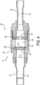
- Fig. 1 is a drawing depicting an isometric view of an exemplary isolation valve assembly 10 in accordance with embodiments of the present invention.
- the isolation valve assembly 10 includes a valve body 12.
- the valve body 12 includes an inlet portion 14, an outlet portion 16, and a center portion 18, which define a main fluid pathway through the isolation valve assembly by which fluid may flow through the valve body from the inlet to the outlet.
- the center portion 18 defines cavities that house the valve components including a pressure relief feature.
- the valve body may include a variety of joints, fittings, and similar components as are known in the art, which permit connecting the isolation valve assembly within a broader fluid system.
- an isolating element is located in the center portion and is configured to control a flow of a fluid along the main flow pathway from the inlet portion to the outlet portion.
- the isolating element may be a ball that is rotatable between an open position and a closed position to control a flow of a fluid along a main flow pathway from the inlet portion to the outlet portion.
- a pressure relief feature is disposed integrally within the center portion of the valve body to permit a relief flow bypassing the main flow pathway when a pressure differential from the inlet portion to the outlet portion exceeds a threshold.
- the center portion defines a relief passage around the isolating element to permit the relief flow to flow from the pressure relief feature around the isolating element to the outlet portion when the pressure differential from the inlet portion to the outlet portion exceeds the threshold.
- Figs. 2-4 depict various cross-sectional views of an isolation valve assembly 10 comparable to the isolation valve assembly of Fig. 1 .
- Fig. 2 is a drawing depicting a side cross-sectional view the exemplary isolation valve assembly 10 in accordance with embodiments of the present invention, with the valve assembly being in the closed position.
- Fig. 3 is a drawing depicting a side cross-sectional view of the exemplary isolation valve assembly 10 of Fig. 2 , with the valve assembly being in the open position.
- Fig. 4 is a drawing depicting a top cross-sectional view of the isolation valve assembly 10 of Fig. 2 , with the valve assembly being in the closed position.
- the isolation valve assembly 10 may be configured as a ball valve assembly 10 including a rotating ball 20 as the isolating element.
- the isolating element/ball 20 is moveable between a first or closed position ( Fig. 2 ) and a second or open position ( Fig. 3 ).
- the valve body defines the main flow pathway comprising an inlet 22 and an outlet 24.
- the ball 20 is located in the main flow pathway and is moveable between an open position and a closed position.
- the ball defines an open pathway through the ball, wherein when the ball is in the open position the open pathway fluidly connects the inlet 22 to the outlet 24 to complete the main flow pathway, and when the ball is in the closed position the ball blocks the main flow pathway between the inlet and the outlet.
- the cross-sectional views show the main flow pathway from an inlet pathway 22 through the inlet portion 14 of the valve body, to an outlet pathway 24 through the outlet portion 16 of the valve body.
- the valve components including the ball 20 are housed within the center portion 18 of the valve body 12.
- the ball 20 includes a wall 26 that defines an open pathway 28 through the ball. In the first or closed position of ball 20 shown in Fig. 2 , the wall 26 is positioned to block the main flow pathway between the inlet and outlet pathways 22, 24, and the open pathway 28 of the ball 20 is not in fluid communication with the inlet pathway 22. In the second or open position of Fig. 3 , the ball 20 has rotated to the second or open position.
- the open pathway 28 though the ball is now in fluid communication with both the inlet and outlet fluid pathways 22, 24 so as to complete the main flow pathway through the ball valve assembly 10.
- the open pathway 28 fluidly connects the inlet portion directly to the outlet portion of the valve body to complete the main flow pathway when the ball is in the open position.
- the wall 26 blocks flow directly from the inlet portion to the outlet portion when the valve assembly is in the closed position.
- a relief flow bypasses the main flow pathway through a pressure relief feature when the pressure differential for the inlet to the outlet exceeds a threshold.
- the threshold is a predetermined property of the system based on the specific system and properties of the system configuration, and is readily ascertainable to one of ordinary skill in the art. Accordingly, one skilled in the art would understand how to configure the pressure relief feature to provide a relief flow in response to any pressure differential threshold that may be applicable.
- Control of flow through the main flow pathway is achieved by operation of a valve stem 30 that is operable to drive the ball 20 between the open position and the closed position.
- the valve stem 30 may include a control element 32 that cooperates with a portion of the ball 20 to move ball 20 between the open and closed positions.
- the control element 32 may constitute a key 34 that fits within a key slot 36 in the ball. With such configuration, operation of the valve stem 30 results in the control element 32 interacting against the ball 20 drive the ball into either of the first/closed or second/open positions.
- the valve stem 30 also may be sealed against the valve body 12 by one or more shaft seals 40.
- the shafts seals may be o-ring seals or other suitable annular sealing elements that extend around the valve stem 30.
- the ball 20 may be sealed against the valve body by annular ball seals 42 and 44.
- the ball seal 42 may be provided on the inlet side, and the ball seal 44 may be provided on the outlet side, so as to seal the ball relative to the main flow pathway.
- the present invention includes an enhanced pressure relief feature 50.
- the pressure relief feature is disposed in a bypass channel that is in fluid communication with the inlet, and the valve body further defines a pressure relief passage comprising a clearance between an outer surface of the ball and the valve body.
- the pressure relief feature is configured to permit a relief flow from the bypass channel through the pressure relief passage to the outlet.
- Fig. 2 in particular shows the pressure relief feature 50 both as incorporated into the isolation valve assembly 10, and a more close-up view so as to illustrate details of the pressure relief feature 50.
- the pressure relief feature 50 may be disposed in a bypass channel 52 that is defined by the valve body and extends from the inlet fluid pathway 22 and through the center portion 18 of the valve body 12.
- the pressure relief feature more specifically may be configured as a pressure relief valve 54.
- the bypass channel 52 leads to the pressure relief valve 54.
- the pressure relief valve 54 may be configured as a ball check valve, although any suitable valve known in the art for relieving pressure may be employed.
- the close-up view portion of Fig. 2 depicts details of the pressure relief valve 54 in the example configuration in which such pressure relief valve 54 is configured as a ball check valve.
- the pressure relief valve 54 may include a check ball 56 that is biased by an elastic element 58 against a valve seat portion 60 of the valve body to a closed position.
- the elastic element 58 may be configured as a biasing spring.
- the pressure relief valve 54 further may include a check valve cage 61 that retains the spring and ball in the check valve assembly. That cage has cross holes to allow flow to escape an go through the assembly when the ball is moved from the seat, and the cage also serves as a stop for the ball in the open direction.
- the check ball when the isolation ball 20 is in the closed position and the pressure differential exceeds the threshold, the check ball is configured to move off the valve seat to permit the relief flow through the pressure relief feature.
- the pressure relief valve 54 opens to permit a pressure relief flow from the inlet pathway 22 through the bypass channel 52 and the pressure relief valve 54, and ultimately out through the outlet pathway 24.
- the excessive pressure differential may move the check ball 56 off of the valve seat 60 against the bias of the elastic element 58 to an open position. With the check ball moved off the valve seat to the open position, a relief flow is now permitted from the bypass channel 52 and through the pressure relief valve 54.
- the pressure differential across the isolation valve assembly 10 will then decrease due to the pressure relief flow. Once the pressure differential falls below the threshold, the bias of the elastic element 58 will dominate and force the check ball 56 back into the closed position against the valve seat 60.
- Fig. 4 is a drawing depicting a top cross-sectional view of the exemplary ball valve assembly of Fig. 2 , with the valve assembly being in the closed position.
- a pressure relief passage 62 constituting a clearance between the isolation ball 20 and the valve body 12 in the area of the ball seals 42 and 44.
- the pressure relief valve 54 is open, the relief flow flows through the pressure relief valve 54 via valve flow passages 63 to the pressure relief passage 62.
- the pressure relief passage 62 permits the relief flow to proceed around an outer surface of the ball 20 and past the ball seals 42 and 44.
- the flow around the ball 20 can proceed into and through the open pathway 28 defined by the ball 20.
- the open pathway 28 fluidly connects the pressure relief passage 62 to the outlet pathway 24.
- the relief flow may exit the ball 20 through a relief outlet 64 that fluidly connects the open pathway 28 with the outlet pathway 24 when the ball 20 is in the first or closed position. In this manner, a relief flow proceeds through the isolation valve assembly 10 so as to relieve any excess pressure build-up on the inlet side of the valve.
- the configuration of the pressure relief feature 50 of the present invention has significant advantages over conventional configurations.
- the isolation ball valve assembly 10 is configured with such pressure relief feature 50 integral within the valve body 12.
- the integral configuration reduces the number of braze joints as compared to existing two-valve solutions with multiple parallel flow pathways, thereby reducing cost in brazing materials, labor to create the joints, and materials. By reducing the number of braze joints, potential leak paths through the system also are reduced which enhances valve reliability.
- Fig. 5 is a drawing depicting a side cross-sectional view of an alternative embodiment of an exemplary ball valve assembly 10 in accordance with embodiments of the present invention, with the valve assembly being in the closed position. Accordingly, like components in Fig. 5 are identified with the same reference numerals as in Figs. 1-4 .
- the embodiment of Fig. 5 is characterized by an alternative configuration of a pressure relief feature, denoted in Fig. 5 as pressure relief feature 70.
- Fig. 6 is a drawing depicting a close-up view of the ball valve assembly of Fig. 5 in the area of the pressure relief feature 70.
- the pressure relief feature 70 may be disposed in a first bypass channel 72 that extends from the inlet fluid pathway 22 and through the center portion 18 of the valve body 12.
- the bypass channel 72 leads to a pressure relief valve 74.
- the pressure relief valve 74 may include rigid valve seat 76 that is fixed within the valve body 12.
- the rigid valve seat may be made of steel.
- the valve seat may define a flow passage 78 that is in fluid communication with the first bypass channel 72.
- the pressure relief valve 74 further includes a moveable poppet 80 that is biased by an elastic element 82 against the valve seat 76 to a closed position.
- the elastic element 82 may be configured as a biasing spring.
- the efficacy of the closed position may be enhanced by a gasket element 84, which may be made of Teflon® or comparable suitable material, that is formed into the poppet 80.
- the poppet 80 may include passages 81 that permit a flow through the poppet when the poppet is in the open position.
- the valve assembly further may include a cap 86 that is connectable to the valve body 12 and houses at least a portion of the pressure relief valve 74.
- the elastic element 82 may be housed within the cap 86 that is connectable to the valve body 12.
- the cap 86 may be threadably connected to the valve body, connectable with a snap fit, or by any other suitable means.
- the poppet when the isolation ball 20 is in the closed position and the pressure differential from the inlet to the outlet exceeds the threshold, the poppet is configured to move off the valve seat to permit the relief flow through the pressure relief feature.
- the pressure relief valve 74 opens to permit a pressure relief flow from the inlet pathway 22 through the bypass channel 72 and the pressure relief valve 74, and ultimately out through the outlet pathway 24.
- the excessive pressure differential may move the poppet 80 off of the valve seat 76 against the bias of the elastic element 82 to an open position.
- the second bypass channel 88 fluidly connects the pressure relief valve 74 to the pressure relief passage 62.
- the configuration of the isolation valve assembly and resultant relief flow is comparable to the previous embodiment.
- the relief passage 62 constituting a clearance between the isolation ball 20 and the valve body 12.
- the relief passage 62 permits the relief flow to proceed around an outer surface of the ball 20 past the ball seals 42 and 44.
- the flow around the ball 20 can proceed into and through the open pathway 28 defined by the ball 20.
- the relief flow then may exit the ball 20 through the relief outlet 64 that is in fluid communication with the outlet pathway 24 when the ball 20 is in the first or closed position. In this manner, a relief flow proceeds through the isolation valve assembly 10 so as to relieve any excess pressure build-up.
- the valve assembly includes a valve body defining a main flow pathway comprising an inlet and an outlet, and defining a bypass channel in fluid communication with the inlet; a ball located in the main flow pathway and that is moveable between an open position and a closed position; the ball defining an open pathway through the ball wherein when the ball is in the open position the open pathway fluidly connects the inlet to the outlet to complete the main flow pathway, and when the ball is in the closed position the ball blocks the main flow pathway between the inlet and the outlet; a pressure relief feature disposed in the bypass channel; and the valve body further defining a pressure relief passage comprising a clearance between an outer surface of the ball and the valve body.
- the pressure relief feature When the ball is in the closed position and a pressure differential from the inlet to the outlet exceeds a threshold, the pressure relief feature is configured to permit a relief flow from the bypass channel through the pressure relief passage to the outlet.
- the valve assembly may include one or more of the following features, either individually or in combination.
- the open pathway fluidly connects the pressure relief passage to the outlet.
- the ball further defines a relief outlet, and when the ball is in the closed position, the relief outlet fluidly connects the open pathway to the outlet.
- the pressure relief feature comprises a ball check valve including a check ball that is biased by an elastic element against a valve seat portion of the valve body.
- the elastic element is a biasing spring.
- the pressure relief feature further comprises a cage that retains the spring and check ball.
- the check ball when the ball is in the closed position and the pressure differential exceeds the threshold, the check ball is configured to move off the valve seat to permit the relief flow through the pressure relief feature.
- the pressure relief feature comprises a poppet that is biased by an elastic element against a rigid valve seat fixed within the valve body.
- the elastic element is a biasing spring.
- the poppet when the ball is in the closed position and the pressure differential exceeds the threshold, the poppet is configured to move off the valve seat to permit the relief flow through the pressure relief feature.
- valve body defines a second bypass channel that fluidly connects the pressure relief feature to the pressure relief passage.
- valve assembly further includes a cap that is connectable to the valve body and configured to house at least a portion of the pressure relief feature.
- the valve assembly may include a valve body including an inlet portion, an outlet portion, and a center portion that connects the inlet portion to the outlet portion; an isolating element located in the center portion and configured to control a flow of a fluid along a main flow pathway from the inlet portion to the outlet portion; a pressure relief feature disposed integrally within the center portion of the valve body to permit a relief flow bypassing the main flow pathway when a pressure differential from the inlet portion to the outlet portion exceeds a threshold; and the center portion defining a relief passage around the isolating element to permit the relief flow to flow from the pressure relief feature around the isolating element to the outlet portion when the pressure differential exceeds the threshold.
- the other embodiment of the valve assembly may include one or more of the following features, either individually or in combination.
- the isolating element comprises a ball that is moveable between an open position and a closed position to control a flow of a fluid along a main flow pathway from the inlet portion to the outlet portion.
- the ball defines an open pathway and a relief outlet for communicating the relief flow from the relief passage to the outlet portion when the ball is in the closed position.
- the open pathway fluidly connects the inlet portion directly to the outlet portion to complete the main flow pathway when the ball is in the open position.
- the ball has a wall that blocks flow directly from the inlet portion to the outlet portion when the valve assembly is in the closed position, and the relief flow bypasses the main flow pathway through the pressure relief feature when the pressure differential exceeds the threshold.
- valve assembly further includes a valve stem that is operable to drive the ball between the open position and the closed position.
- the pressure relief feature comprises a ball check valve including a check ball that is biased by an elastic element against a valve seat portion of the valve body.
- the pressure relief feature comprises a poppet that is biased by an elastic element against a rigid valve seat fixed within the valve body, and the valve assembly further includes a cap that is connectable to the valve body and configured to house at least a portion of the pressure relief feature.
Landscapes
- Engineering & Computer Science (AREA)
- General Engineering & Computer Science (AREA)
- Mechanical Engineering (AREA)
- Safety Valves (AREA)
Description
- The present invention relates generally to isolation valves for isolating adjacent portions of a fluid pathway, such as isolation ball valves, and more particularly to pressure relief features of isolation or ball valve assemblies.
- Isolation valves are a common valve type for isolating adjacent portions of a fluid pathway. A common configuration of an isolation valve is a ball valve that is rotatable between a closed position for blocking fluid flow, and an open position for permitting fluid flow between the adjacent portions of the fluid pathway. An exemplary use of a ball valve of such type is in controlling the flow of a refrigerant through a refrigeration system, such as may be used in a grocery store, storage facility, or like location. Refrigeration systems in such locations may employ multiple refrigerators linked to a common refrigerant source and common or connected flow pathways. Ball valves may be used to control a flow of refrigerant through the system among the individual refrigerators. A ball valve, for example, typically is provided at the inlet and outlet of a refrigerated display case.
- In many applications that employ isolation valves, and ball valves in particular, pressure build-up in the fluid system can give rise to safety concerns. This concern can be particularly pronounced in refrigeration systems that operate at high pressure, especially for example in systems in which carbon dioxide is the refrigerant. When closed, the ball valve stops the flow of refrigerant in the system. Trapped refrigerant can warm up while the ball valve is closed, which can cause pressure in the system to build leading to a potentially unsafe condition This issue is particularly acute with carbon dioxide refrigerant because a small change in temperature results in a substantial spike in pressure.
- To address the safety issue associated with pressure build-up, ball valve assemblies may be provided with pressure relief features. Conventional ball valve assemblies utilize two valves to relieve the pressure. In such systems, a ball valve and a check valve are typically piped in parallel with one another, with the check valve bleeding off excess pressure. This conventional configuration employing multiple, parallel pathways typically includes several joints that must be brazed together. The conventional configuration is therefore deficient in that the need for several joints brazed together increases the size and number of components in the ball valve assembly, thereby increasing cost and providing for less efficient functioning of the ball valve than is desirable.
-
WO2012/048369 discloses a valve assembly for controlling the flow of a fluid, the valve assembly including a main body with an inlet and an outlet, the main body including: a primary fluid flow path from the inlet to the outlet, the primary flow path being closable by a first valve member; and, a secondary fluid flow path providing an alternative flow path from the inlet to the outlet, the secondary fluid flow path being closable by a second valve member, wherein a pressure difference between the fluid at the inlet and the fluid at the outlet causes the second valve member to open and allow the fluid to flow via the secondary fluid flow path. -
US2014/251472 discloses a bypass valve assembly configured to provide a secondary fluid passage around a valve. The secondary fluid passage includes a regulator device that selectively restricts the fluid flow through the secondary passage. During pressure spikes, the regulator device is configured to open so as to relieve pressure in the system and prevent failure of the valve. - The present invention provides a valve assembly according to claim 1. Optional features are recited in dependent claims.
- The present invention provides an isolation valve assembly, in the form of a ball valve assembly that overcomes the deficiencies of conventional configurations. The ball valve assembly of the present invention includes an enhanced pressure relief feature that has a pressure relief valve that is built into the valve body that allows refrigerant or other fluid to flow past the ball valve and through a pressure relief outlet. In particular, flow passages may be configured to allow fluid to flow around the ball and past the ball seals in the ball valve so as to relieve any pressure build-up within the system. The ball valve assembly with the pressure relief feature of the present invention reduces the number of braze joints as compared to the conventional parallel two-valve configuration, thereby reducing cost in brazing materials, labor to create the joints, and materials. By reducing the number of braze joints, the present invention also reduces potential leak points through the system, which enhances valve reliability.
- The valve assembly in exemplary embodiments includes a valve body defining a main flow pathway comprising an inlet and an outlet, and defining a bypass channel in fluid communication with the inlet. A ball is located in the main flow pathway and that is moveable between an open position and a closed position. The ball defines an open pathway through the ball wherein when the ball is in the open position the open pathway fluidly connects the inlet to the outlet to complete the main flow pathway, and when the ball is in the closed position the ball blocks the main flow pathway directly between the inlet and the outlet. A pressure relief feature is disposed in the bypass channel, and the valve body further defines a pressure relief passage comprising a clearance between an outer surface of the ball and the valve body. When the ball is in the closed position and a pressure differential from the inlet to the outlet exceeds a threshold, the pressure relief feature is configured to permit a relief flow from the bypass channel through the pressure relief passage to the outlet.
- These and further features of the present invention will be apparent with reference to the following description and attached drawings. In the description and drawings, particular embodiments of the invention have been disclosed in detail as being indicative of some of the ways in which the principles of the invention may be employed, but it is understood that the invention is not limited correspondingly in scope. Rather, the invention includes all changes, modifications and equivalents coming within the scope of the claims appended hereto. Features that are described and/or illustrated with respect to one embodiment may be used in the same way or in a similar way in one or more other embodiments and/or in combination with or instead of the features of the other embodiments.
-
-
Fig. 1 is a drawing depicting an isometric view of an exemplary isolation valve assembly in accordance with embodiments of the present invention. -
Fig. 2 is a drawing depicting a side cross-sectional view of an exemplary isolation valve configured as a ball valve assembly in accordance with embodiments of the present invention, with the ball valve assembly being in the closed position. -
Fig. 3 is a drawing depicting a side cross-sectional view of the exemplary ball valve assembly ofFig. 2 , with the ball valve assembly being in the open position. -
Fig. 4 is a drawing depicting a top cross-sectional view of the exemplary ball valve assembly ofFig. 2 , with the ball valve assembly being in the closed position. -
Fig. 5 is a drawing depicting a side cross-sectional view of an alternative embodiment of an exemplary ball valve assembly in accordance with embodiments of the present invention, with the ball valve assembly being in the closed position. -
Fig. 6 is a drawing depicting a close-up view of the ball valve assembly ofFig. 5 in the area of a pressure relief valve in accordance with embodiments of the present invention. - Embodiments of the present invention will now be described with reference to the drawings, wherein like reference numerals are used to refer to like elements throughout. It will be understood that the figures are not necessarily to scale.
-
Fig. 1 is a drawing depicting an isometric view of an exemplaryisolation valve assembly 10 in accordance with embodiments of the present invention. Theisolation valve assembly 10 includes avalve body 12. Thevalve body 12 includes aninlet portion 14, anoutlet portion 16, and acenter portion 18, which define a main fluid pathway through the isolation valve assembly by which fluid may flow through the valve body from the inlet to the outlet. As further detailed below, thecenter portion 18 defines cavities that house the valve components including a pressure relief feature. The valve body may include a variety of joints, fittings, and similar components as are known in the art, which permit connecting the isolation valve assembly within a broader fluid system. - In general, as further detailed below in exemplary embodiments, an isolating element is located in the center portion and is configured to control a flow of a fluid along the main flow pathway from the inlet portion to the outlet portion. The isolating element may be a ball that is rotatable between an open position and a closed position to control a flow of a fluid along a main flow pathway from the inlet portion to the outlet portion. A pressure relief feature is disposed integrally within the center portion of the valve body to permit a relief flow bypassing the main flow pathway when a pressure differential from the inlet portion to the outlet portion exceeds a threshold. The center portion defines a relief passage around the isolating element to permit the relief flow to flow from the pressure relief feature around the isolating element to the outlet portion when the pressure differential from the inlet portion to the outlet portion exceeds the threshold.
-
Figs. 2-4 depict various cross-sectional views of anisolation valve assembly 10 comparable to the isolation valve assembly ofFig. 1 . In particular,Fig. 2 is a drawing depicting a side cross-sectional view the exemplaryisolation valve assembly 10 in accordance with embodiments of the present invention, with the valve assembly being in the closed position.Fig. 3 is a drawing depicting a side cross-sectional view of the exemplaryisolation valve assembly 10 ofFig. 2 , with the valve assembly being in the open position.Fig. 4 is a drawing depicting a top cross-sectional view of theisolation valve assembly 10 ofFig. 2 , with the valve assembly being in the closed position. - As seen in
Figs. 2-4 , theisolation valve assembly 10 may be configured as aball valve assembly 10 including arotating ball 20 as the isolating element. The isolating element/ball 20 is moveable between a first or closed position (Fig. 2 ) and a second or open position (Fig. 3 ). Generally, as further detailed below the valve body defines the main flow pathway comprising aninlet 22 and anoutlet 24. Theball 20 is located in the main flow pathway and is moveable between an open position and a closed position. The ball defines an open pathway through the ball, wherein when the ball is in the open position the open pathway fluidly connects theinlet 22 to theoutlet 24 to complete the main flow pathway, and when the ball is in the closed position the ball blocks the main flow pathway between the inlet and the outlet. - Referring to the specific exemplary embodiment depicted in the figures, the cross-sectional views show the main flow pathway from an
inlet pathway 22 through theinlet portion 14 of the valve body, to anoutlet pathway 24 through theoutlet portion 16 of the valve body. The valve components including theball 20 are housed within thecenter portion 18 of thevalve body 12. Theball 20 includes awall 26 that defines anopen pathway 28 through the ball. In the first or closed position ofball 20 shown inFig. 2 , thewall 26 is positioned to block the main flow pathway between the inlet andoutlet pathways open pathway 28 of theball 20 is not in fluid communication with theinlet pathway 22. In the second or open position ofFig. 3 , theball 20 has rotated to the second or open position. In such open position, theopen pathway 28 though the ball is now in fluid communication with both the inlet andoutlet fluid pathways ball valve assembly 10. Accordingly, theopen pathway 28 fluidly connects the inlet portion directly to the outlet portion of the valve body to complete the main flow pathway when the ball is in the open position. In addition, thewall 26 blocks flow directly from the inlet portion to the outlet portion when the valve assembly is in the closed position. As further detailed below, a relief flow bypasses the main flow pathway through a pressure relief feature when the pressure differential for the inlet to the outlet exceeds a threshold. The threshold is a predetermined property of the system based on the specific system and properties of the system configuration, and is readily ascertainable to one of ordinary skill in the art. Accordingly, one skilled in the art would understand how to configure the pressure relief feature to provide a relief flow in response to any pressure differential threshold that may be applicable. - Control of flow through the main flow pathway is achieved by operation of a
valve stem 30 that is operable to drive theball 20 between the open position and the closed position. The valve stem 30 may include acontrol element 32 that cooperates with a portion of theball 20 to moveball 20 between the open and closed positions. In one example configuration shown in the figures, thecontrol element 32 may constitute a key 34 that fits within akey slot 36 in the ball. With such configuration, operation of thevalve stem 30 results in thecontrol element 32 interacting against theball 20 drive the ball into either of the first/closed or second/open positions. - The valve stem 30 also may be sealed against the
valve body 12 by one or more shaft seals 40. The shafts seals may be o-ring seals or other suitable annular sealing elements that extend around thevalve stem 30. In addition, theball 20 may be sealed against the valve body by annular ball seals 42 and 44. Theball seal 42 may be provided on the inlet side, and theball seal 44 may be provided on the outlet side, so as to seal the ball relative to the main flow pathway. - In ordinary operation, in the first or closed position of
Fig. 2 , as referenced above theball wall 26 is positioned to block the main flow pathway directly between the inlet andoutlet pathways open pathway 28 of theball 20 is not in fluid communication with theinlet pathway 22. To open the valve, thevalve stem 30 is operated to drive rotation of the ball to the second or open position ofFig. 3 . In the open position ofFig. 3 , theopen pathway 28 though the ball is now in fluid communication with both the inlet andoutlet fluid pathways ball valve assembly 10. It will be appreciated that in the closed position ofFig. 3 with no flow through the valve assembly, pressure may build up within the isolated section of piping and the valve assembly. In this regard, when a section of pipe is isolated thereby trapping refrigerant between two valves, the refrigerant temperature will start to rise to the ambient temperature. As the temperature rises the pressure will increase. The propensity for a dangerous pressure build-up is particularly an issue for ball valves for refrigeration systems in which a carbon dioxide based refrigerant is utilized because a small temperature increase results in a drastic spike in pressure. - To relieve such potentially dangerous build-up of pressure, the present invention includes an enhanced
pressure relief feature 50. Generally, the pressure relief feature is disposed in a bypass channel that is in fluid communication with the inlet, and the valve body further defines a pressure relief passage comprising a clearance between an outer surface of the ball and the valve body. When the ball is in the closed position and a pressure differential between the inlet and the outlet exceeds the threshold, the pressure relief feature is configured to permit a relief flow from the bypass channel through the pressure relief passage to the outlet.Fig. 2 in particular shows thepressure relief feature 50 both as incorporated into theisolation valve assembly 10, and a more close-up view so as to illustrate details of thepressure relief feature 50. Thepressure relief feature 50 may be disposed in abypass channel 52 that is defined by the valve body and extends from theinlet fluid pathway 22 and through thecenter portion 18 of thevalve body 12. - The pressure relief feature more specifically may be configured as a
pressure relief valve 54. Thebypass channel 52 leads to thepressure relief valve 54. In exemplary embodiments, thepressure relief valve 54 may be configured as a ball check valve, although any suitable valve known in the art for relieving pressure may be employed. The close-up view portion ofFig. 2 depicts details of thepressure relief valve 54 in the example configuration in which suchpressure relief valve 54 is configured as a ball check valve. Thepressure relief valve 54 may include acheck ball 56 that is biased by anelastic element 58 against avalve seat portion 60 of the valve body to a closed position. Theelastic element 58 may be configured as a biasing spring. Thepressure relief valve 54 further may include acheck valve cage 61 that retains the spring and ball in the check valve assembly. That cage has cross holes to allow flow to escape an go through the assembly when the ball is moved from the seat, and the cage also serves as a stop for the ball in the open direction. - In general, when the
isolation ball 20 is in the closed position and the pressure differential exceeds the threshold, the check ball is configured to move off the valve seat to permit the relief flow through the pressure relief feature. Referring to the figures, when the pressure differential subjected to thebypass channel 52 of theisolation valve assembly 10 builds up above the threshold pressure differential, thepressure relief valve 54 opens to permit a pressure relief flow from theinlet pathway 22 through thebypass channel 52 and thepressure relief valve 54, and ultimately out through theoutlet pathway 24. For example, the excessive pressure differential may move thecheck ball 56 off of thevalve seat 60 against the bias of theelastic element 58 to an open position. With the check ball moved off the valve seat to the open position, a relief flow is now permitted from thebypass channel 52 and through thepressure relief valve 54. The pressure differential across theisolation valve assembly 10 will then decrease due to the pressure relief flow. Once the pressure differential falls below the threshold, the bias of theelastic element 58 will dominate and force thecheck ball 56 back into the closed position against thevalve seat 60. - Details of the relief flow pathway are particularly illustrated with reference to
Fig. 2 and additionallyFig. 4. Fig. 4 is a drawing depicting a top cross-sectional view of the exemplary ball valve assembly ofFig. 2 , with the valve assembly being in the closed position. As seen in such figures, in a region adjacent thepressure relief valve 54, there is defined apressure relief passage 62 constituting a clearance between theisolation ball 20 and thevalve body 12 in the area of the ball seals 42 and 44. When thepressure relief valve 54 is open, the relief flow flows through thepressure relief valve 54 viavalve flow passages 63 to thepressure relief passage 62. Thepressure relief passage 62 permits the relief flow to proceed around an outer surface of theball 20 and past the ball seals 42 and 44. As seen best in the top view ofFig. 4 , the flow around theball 20 can proceed into and through theopen pathway 28 defined by theball 20. Theopen pathway 28 fluidly connects thepressure relief passage 62 to theoutlet pathway 24. In particular, the relief flow may exit theball 20 through arelief outlet 64 that fluidly connects theopen pathway 28 with theoutlet pathway 24 when theball 20 is in the first or closed position. In this manner, a relief flow proceeds through theisolation valve assembly 10 so as to relieve any excess pressure build-up on the inlet side of the valve. - The configuration of the
pressure relief feature 50 of the present invention has significant advantages over conventional configurations. The isolationball valve assembly 10 is configured with suchpressure relief feature 50 integral within thevalve body 12. The integral configuration reduces the number of braze joints as compared to existing two-valve solutions with multiple parallel flow pathways, thereby reducing cost in brazing materials, labor to create the joints, and materials. By reducing the number of braze joints, potential leak paths through the system also are reduced which enhances valve reliability. -
Fig. 5 is a drawing depicting a side cross-sectional view of an alternative embodiment of an exemplaryball valve assembly 10 in accordance with embodiments of the present invention, with the valve assembly being in the closed position. Accordingly, like components inFig. 5 are identified with the same reference numerals as inFigs. 1-4 . The embodiment ofFig. 5 is characterized by an alternative configuration of a pressure relief feature, denoted inFig. 5 aspressure relief feature 70.Fig. 6 is a drawing depicting a close-up view of the ball valve assembly ofFig. 5 in the area of thepressure relief feature 70. - The
pressure relief feature 70, similarly as in the previous embodiment, may be disposed in afirst bypass channel 72 that extends from theinlet fluid pathway 22 and through thecenter portion 18 of thevalve body 12. Thebypass channel 72 leads to apressure relief valve 74. In the embodiment ofFig. 5 , thepressure relief valve 74 may includerigid valve seat 76 that is fixed within thevalve body 12. In exemplary embodiments, the rigid valve seat may be made of steel. The valve seat may define aflow passage 78 that is in fluid communication with thefirst bypass channel 72. Thepressure relief valve 74 further includes amoveable poppet 80 that is biased by anelastic element 82 against thevalve seat 76 to a closed position. Theelastic element 82 may be configured as a biasing spring. The efficacy of the closed position may be enhanced by agasket element 84, which may be made of Teflon® or comparable suitable material, that is formed into thepoppet 80. Thepoppet 80 may includepassages 81 that permit a flow through the poppet when the poppet is in the open position. The valve assembly further may include acap 86 that is connectable to thevalve body 12 and houses at least a portion of thepressure relief valve 74. For example, theelastic element 82 may be housed within thecap 86 that is connectable to thevalve body 12. Thecap 86 may be threadably connected to the valve body, connectable with a snap fit, or by any other suitable means. - In general, when the
isolation ball 20 is in the closed position and the pressure differential from the inlet to the outlet exceeds the threshold, the poppet is configured to move off the valve seat to permit the relief flow through the pressure relief feature. Referring toFigs. 5 and6 , when the pressure differential from the inlet side into the bypass channel of theisolation valve assembly 10 builds up above the threshold, thepressure relief valve 74 opens to permit a pressure relief flow from theinlet pathway 22 through thebypass channel 72 and thepressure relief valve 74, and ultimately out through theoutlet pathway 24. For example, the excessive pressure differential may move thepoppet 80 off of thevalve seat 76 against the bias of theelastic element 82 to an open position. With the poppet moved off the valve seat to the open position, a relief flow is now permitted from thebypass channel 72 and through flowpassage flow passage 78 in the valve seat and further through thepassages 81 in thepoppet 80. The relief flow can then flow through asecond bypass channel 88 defined by thevalve body 12 and toward theisolation ball 20. As in the previous embodiment, the pressure differential across theisolation valve assembly 10 will then decrease due to the pressure relief flow. Once the pressure differential falls below the threshold, the bias of theelastic element 82 will dominate and force thepoppet 80 back into the closed position against thevalve seat 76. - In the embodiment of
Figs. 5 and6 , thesecond bypass channel 88 fluidly connects thepressure relief valve 74 to thepressure relief passage 62. Once the relief flow proceeds through thesecond bypass channel 88, the configuration of the isolation valve assembly and resultant relief flow is comparable to the previous embodiment. Similarly as described above, in the embodiment ofFig. 5 there is therelief passage 62 constituting a clearance between theisolation ball 20 and thevalve body 12. When thepressure relief valve 74 is open, therelief passage 62 permits the relief flow to proceed around an outer surface of theball 20 past the ball seals 42 and 44. The flow around theball 20 can proceed into and through theopen pathway 28 defined by theball 20. The relief flow then may exit theball 20 through therelief outlet 64 that is in fluid communication with theoutlet pathway 24 when theball 20 is in the first or closed position. In this manner, a relief flow proceeds through theisolation valve assembly 10 so as to relieve any excess pressure build-up. - An aspect of the invention, therefore, is a valve assembly. In exemplary embodiments, the valve assembly includes a valve body defining a main flow pathway comprising an inlet and an outlet, and defining a bypass channel in fluid communication with the inlet; a ball located in the main flow pathway and that is moveable between an open position and a closed position; the ball defining an open pathway through the ball wherein when the ball is in the open position the open pathway fluidly connects the inlet to the outlet to complete the main flow pathway, and when the ball is in the closed position the ball blocks the main flow pathway between the inlet and the outlet; a pressure relief feature disposed in the bypass channel; and the valve body further defining a pressure relief passage comprising a clearance between an outer surface of the ball and the valve body. When the ball is in the closed position and a pressure differential from the inlet to the outlet exceeds a threshold, the pressure relief feature is configured to permit a relief flow from the bypass channel through the pressure relief passage to the outlet. The valve assembly may include one or more of the following features, either individually or in combination.
- In an exemplary embodiment of the valve assembly, when the ball is in the closed position, the open pathway fluidly connects the pressure relief passage to the outlet.
- In an exemplary embodiment of the valve assembly, the ball further defines a relief outlet, and when the ball is in the closed position, the relief outlet fluidly connects the open pathway to the outlet.
- In an exemplary embodiment of the valve assembly, the pressure relief feature comprises a ball check valve including a check ball that is biased by an elastic element against a valve seat portion of the valve body.
- In an exemplary embodiment of the valve assembly, the elastic element is a biasing spring.
- In an exemplary embodiment of the valve assembly, the pressure relief feature further comprises a cage that retains the spring and check ball.
- In an exemplary embodiment of the valve assembly, when the ball is in the closed position and the pressure differential exceeds the threshold, the check ball is configured to move off the valve seat to permit the relief flow through the pressure relief feature.
- In an exemplary embodiment of the valve assembly, the pressure relief feature comprises a poppet that is biased by an elastic element against a rigid valve seat fixed within the valve body.
- In an exemplary embodiment of the valve assembly, the elastic element is a biasing spring.
- In an exemplary embodiment of the valve assembly, when the ball is in the closed position and the pressure differential exceeds the threshold, the poppet is configured to move off the valve seat to permit the relief flow through the pressure relief feature.
- In an exemplary embodiment of the valve assembly, the valve body defines a second bypass channel that fluidly connects the pressure relief feature to the pressure relief passage.
- In an exemplary embodiment of the valve assembly, the valve assembly further includes a cap that is connectable to the valve body and configured to house at least a portion of the pressure relief feature.
- In another embodiment of the valve assembly, the valve assembly may include a valve body including an inlet portion, an outlet portion, and a center portion that connects the inlet portion to the outlet portion; an isolating element located in the center portion and configured to control a flow of a fluid along a main flow pathway from the inlet portion to the outlet portion; a pressure relief feature disposed integrally within the center portion of the valve body to permit a relief flow bypassing the main flow pathway when a pressure differential from the inlet portion to the outlet portion exceeds a threshold; and the center portion defining a relief passage around the isolating element to permit the relief flow to flow from the pressure relief feature around the isolating element to the outlet portion when the pressure differential exceeds the threshold. The other embodiment of the valve assembly may include one or more of the following features, either individually or in combination.
- According to the invention, the isolating element comprises a ball that is moveable between an open position and a closed position to control a flow of a fluid along a main flow pathway from the inlet portion to the outlet portion.
- In an exemplary embodiment of the valve assembly, the ball defines an open pathway and a relief outlet for communicating the relief flow from the relief passage to the outlet portion when the ball is in the closed position.
- In an exemplary embodiment of the valve assembly, the open pathway fluidly connects the inlet portion directly to the outlet portion to complete the main flow pathway when the ball is in the open position.
- In an exemplary embodiment of the valve assembly, the ball has a wall that blocks flow directly from the inlet portion to the outlet portion when the valve assembly is in the closed position, and the relief flow bypasses the main flow pathway through the pressure relief feature when the pressure differential exceeds the threshold.
- In an exemplary embodiment of the valve assembly, the valve assembly further includes a valve stem that is operable to drive the ball between the open position and the closed position.
- In an exemplary embodiment of the valve assembly, the pressure relief feature comprises a ball check valve including a check ball that is biased by an elastic element against a valve seat portion of the valve body.
- In an exemplary embodiment of the valve assembly, the pressure relief feature comprises a poppet that is biased by an elastic element against a rigid valve seat fixed within the valve body, and the valve assembly further includes a cap that is connectable to the valve body and configured to house at least a portion of the pressure relief feature.
- Although the invention has been shown and described with respect to a certain embodiment or embodiments, it is obvious that equivalent alterations and modifications will occur to others skilled in the art upon the reading and understanding of this specification and the annexed drawings. In particular regard to the various functions performed by the above described elements (components, assemblies, devices, compositions, etc.), the terms (including a reference to a "means") used to describe such elements are intended to correspond, unless otherwise indicated, to any element which performs the specified function of the described element (i.e., that is functionally equivalent), even though not structurally equivalent to the disclosed structure which performs the function in the herein illustrated exemplary embodiment or embodiments of the invention. In addition, while a particular feature of the invention may have been described above with respect to only one or more of several illustrated embodiments, such feature may be combined with one or more other features of the other embodiments, as may be desired and advantageous for any given or particular application.
Claims (12)
- A valve assembly (10) comprising:a valve body (12) defining a main flow pathway comprising an inlet (22) and an outlet (24), and defining a bypass channel (52) in fluid communication with the inlet (22);a ball (20) located in the main flow pathway and that is moveable between an open position and a closed position;the ball (20) defining an open pathway (28) through the ball (20) wherein when the ball (20) is in the open position the open pathway (28) fluidly connects the inlet (22) to the outlet (24) to complete the main flow pathway, and when the ball (20) is in the closed position the ball (20) blocks the main flow pathway between the inlet (22) and the outlet (24);a pressure relief feature (50) disposed in the bypass channel (52); and characterized bythe valve body (12) further defining a pressure relief passage (62) comprising a clearance between an outer surface of the ball (20) and the valve body (12);wherein when the ball (20) is in the closed position and a pressure differential from the inlet (22) to the outlet (24) exceeds a threshold, the pressure relief feature (50) is configured to permit a relief flow from the bypass channel (52) through the pressure relief passage (62) to the outlet (24).
- The valve assembly (10) of claim 1, wherein when the ball (20) is in the closed position, the open pathway (28) fluidly connects the pressure relief passage (62) to the outlet (24).
- The valve assembly (10) of claim 2, wherein the ball (20) further defines a relief outlet (64), and when the ball (20) is in the closed position, the relief outlet (64) fluidly connects the open pathway (28) to the outlet (24).
- The valve assembly (10) of any of claims 1-3, wherein the pressure relief feature (50) comprises a ball check valve including a check ball (56) that is biased by an elastic element (58) against a valve seat portion (60) of the valve body (12).
- The valve assembly (10) of claim 4, wherein the elastic element (58) is a biasing spring.
- The valve assembly (10) of claim 5, wherein the pressure relief feature (50) further comprises a cage (61) that retains the spring (58) and check ball (56).
- The valve assembly (10) of any of claims 4-6, wherein when the ball (20) is in the closed position and the pressure differential exceeds the threshold, the check ball (56) is configured to move off the valve seat (60) to permit the relief flow through the pressure relief feature (50).
- The valve assembly (10) of any of claims 1-3, wherein the pressure relief feature (50) comprises a poppet (80) that is biased by an elastic element (82) against a rigid valve seat (76) fixed within the valve body (12).
- The valve assembly (10) of claim 8, wherein the elastic element (82) is a biasing spring.
- The valve assembly (10) of any of claims 8-9, wherein when the ball (20) is in the closed position and the pressure differential exceeds the threshold, the poppet (80) is configured to move off the valve seat (76) to permit the relief flow through the pressure relief feature (50).
- The valve assembly (10) of claim 10, wherein the valve body (12) defines a second bypass channel (88) that fluidly connects the pressure relief feature (50) to the pressure relief passage (62).
- The valve assembly (10) of by of claims 8-11, further comprising a cap (86) that is connectable to the valve body (12) and configured to house at least a portion of the pressure relief feature (50).
Applications Claiming Priority (2)
| Application Number | Priority Date | Filing Date | Title |
|---|---|---|---|
| US201562160633P | 2015-05-13 | 2015-05-13 | |
| PCT/US2015/065748 WO2016182599A1 (en) | 2015-05-13 | 2015-12-15 | Ball valve with pressure relief feature |
Publications (2)
| Publication Number | Publication Date |
|---|---|
| EP3295067A1 EP3295067A1 (en) | 2018-03-21 |
| EP3295067B1 true EP3295067B1 (en) | 2019-11-20 |
Family
ID=55168387
Family Applications (1)
| Application Number | Title | Priority Date | Filing Date |
|---|---|---|---|
| EP15825695.8A Active EP3295067B1 (en) | 2015-05-13 | 2015-12-15 | Ball valve with pressure relief feature |
Country Status (5)
| Country | Link |
|---|---|
| US (1) | US10107406B2 (en) |
| EP (1) | EP3295067B1 (en) |
| CA (1) | CA2984489C (en) |
| DK (1) | DK3295067T3 (en) |
| WO (1) | WO2016182599A1 (en) |
Families Citing this family (10)
| Publication number | Priority date | Publication date | Assignee | Title |
|---|---|---|---|---|
| WO2014176430A1 (en) * | 2013-04-25 | 2014-10-30 | Ohio University | Emergency shutdown valves with bypass features |
| KR101860462B1 (en) * | 2016-06-08 | 2018-05-23 | 한국항공우주연구원 | Apparatus of being coupled pintle regulator to ball valve and driving method thereof |
| US11209090B2 (en) * | 2018-03-02 | 2021-12-28 | Marshall Excelsior Co. | Bypass valve assembly with integrated flow control valve |
| CN109340407A (en) * | 2018-09-14 | 2019-02-15 | 镇江努塞尔热能科技有限公司 | Right angle ball valve with decompression function |
| BR112022004394A2 (en) * | 2019-10-11 | 2022-05-31 | Halliburton Energy Services Inc | Multiple ball valve set |
| IT201900023862A1 (en) * | 2019-12-12 | 2021-06-12 | Greiner Spa | Valve equipped with a bypass channel |
| CN111255909A (en) * | 2020-01-17 | 2020-06-09 | 浙江大学 | Ultra-low temperature ball valve body cavity abnormity-preventing boosting device with self-closing function and method thereof |
| IT202000012049A1 (en) * | 2020-05-22 | 2021-11-22 | Rubinetterie Bresciane Bonomi S P A | BALL VALVE WITH MINIMUM FLOW GUARANTEED |
| US12025205B2 (en) * | 2021-04-22 | 2024-07-02 | DRiV Automotive Inc. | Hydraulic rebound stop pressure relief system |
| WO2024176081A1 (en) * | 2023-02-22 | 2024-08-29 | Castel S.R.L. | Ball valve with a retaining system |
Family Cites Families (10)
| Publication number | Priority date | Publication date | Assignee | Title |
|---|---|---|---|---|
| US4813749A (en) * | 1987-12-24 | 1989-03-21 | Dresser Industries, Inc. | Pilot operated stepping directional valve and method for single line operation |
| US4928731A (en) * | 1989-06-22 | 1990-05-29 | Auto-Valve, Inc. | Aircraft toilet tank filling valve assembly |
| US5251459A (en) | 1991-05-28 | 1993-10-12 | Emerson Electric Co. | Thermal expansion valve with internal by-pass and check valve |
| US5277248A (en) | 1992-05-19 | 1994-01-11 | B And E Manufacturing & Supply Co. | Ball valve type injector and catcher apparatus with adjustable flow control for catching and retrieving paraffin cutting balls |
| US7367357B2 (en) | 2005-03-02 | 2008-05-06 | Eaton Corporation | Solenoid ball valve with bypass orifice |
| US7913503B2 (en) | 2008-05-22 | 2011-03-29 | GM Global Technology Operations LLC | Refrigerant expansion assembly with pressure relief |
| JP5106464B2 (en) | 2009-03-30 | 2012-12-26 | サンデン株式会社 | Fluid machine, refrigerant circuit and waste heat utilization apparatus using fluid machine |
| WO2012048369A1 (en) * | 2010-10-11 | 2012-04-19 | Strathbrook Industrial Services Pty Limited | A valve assembly |
| US20140251472A1 (en) * | 2013-03-06 | 2014-09-11 | J-Mac Tool, Inc. | Overpressurization Bypass for Fluid Valve |
| US9377116B2 (en) * | 2013-09-16 | 2016-06-28 | The Boeing Company | Valve and method of relieving overpressure in a fluid supply system |
-
2015
- 2015-12-15 EP EP15825695.8A patent/EP3295067B1/en active Active
- 2015-12-15 DK DK15825695.8T patent/DK3295067T3/en active
- 2015-12-15 CA CA2984489A patent/CA2984489C/en active Active
- 2015-12-15 WO PCT/US2015/065748 patent/WO2016182599A1/en active Application Filing
- 2015-12-15 US US15/569,651 patent/US10107406B2/en active Active
Non-Patent Citations (1)
| Title |
|---|
| None * |
Also Published As
| Publication number | Publication date |
|---|---|
| CA2984489A1 (en) | 2016-11-17 |
| DK3295067T3 (en) | 2020-02-24 |
| CA2984489C (en) | 2023-05-16 |
| US20180112784A1 (en) | 2018-04-26 |
| US10107406B2 (en) | 2018-10-23 |
| EP3295067A1 (en) | 2018-03-21 |
| WO2016182599A1 (en) | 2016-11-17 |
Similar Documents
| Publication | Publication Date | Title |
|---|---|---|
| EP3295067B1 (en) | Ball valve with pressure relief feature | |
| US11806643B2 (en) | Drain valve and valve arrangement | |
| AU2010337322B2 (en) | Apparatus to increase a force of an actuator having an override apparatus | |
| US10228064B2 (en) | Multi-ported refrigeration valve assembly | |
| CA2601074A1 (en) | Fluid flow control device | |
| US20170363217A1 (en) | Main Stage In-Line Pressure Control Cartridge with Optional Reverse Flow Function | |
| EP2932143B1 (en) | Pressure volume regulator | |
| GB2527339A (en) | Valve | |
| US9518670B2 (en) | Main stage in-line pressure control cartridge with stepped retainer collar | |
| WO2012048369A1 (en) | A valve assembly | |
| US20080265199A1 (en) | Zero leakage balance valve system | |
| US20100147388A1 (en) | Directional gate valve | |
| US8528590B2 (en) | Combination solenoid check valve | |
| US20150101687A1 (en) | Liquid Valve Design with internal Check Valve | |
| WO2016205043A1 (en) | Main stage in-line pressure control cartridge with stepped retainer collar | |
| US8091857B2 (en) | Valve | |
| CN111853315B (en) | Valve cover for a multiple-way valve, in particular for a two-way valve | |
| RU2364779C2 (en) | Safety valve | |
| KR20080051097A (en) | System and valve arrangement for fast emergency shut-down of hydraulically actuated valves | |
| CN111853315A (en) | Valve cover for a multi-way valve, in particular for a two-way valve |
Legal Events
| Date | Code | Title | Description |
|---|---|---|---|
| STAA | Information on the status of an ep patent application or granted ep patent |
Free format text: STATUS: THE INTERNATIONAL PUBLICATION HAS BEEN MADE |
|
| PUAI | Public reference made under article 153(3) epc to a published international application that has entered the european phase |
Free format text: ORIGINAL CODE: 0009012 |
|
| STAA | Information on the status of an ep patent application or granted ep patent |
Free format text: STATUS: REQUEST FOR EXAMINATION WAS MADE |
|
| 17P | Request for examination filed |
Effective date: 20171109 |
|
| AK | Designated contracting states |
Kind code of ref document: A1 Designated state(s): AL AT BE BG CH CY CZ DE DK EE ES FI FR GB GR HR HU IE IS IT LI LT LU LV MC MK MT NL NO PL PT RO RS SE SI SK SM TR |
|
| AX | Request for extension of the european patent |
Extension state: BA ME |
|
| DAV | Request for validation of the european patent (deleted) | ||
| DAX | Request for extension of the european patent (deleted) | ||
| GRAP | Despatch of communication of intention to grant a patent |
Free format text: ORIGINAL CODE: EPIDOSNIGR1 |
|
| STAA | Information on the status of an ep patent application or granted ep patent |
Free format text: STATUS: GRANT OF PATENT IS INTENDED |
|
| INTG | Intention to grant announced |
Effective date: 20190802 |
|
| GRAS | Grant fee paid |
Free format text: ORIGINAL CODE: EPIDOSNIGR3 |
|
| GRAA | (expected) grant |
Free format text: ORIGINAL CODE: 0009210 |
|
| STAA | Information on the status of an ep patent application or granted ep patent |
Free format text: STATUS: THE PATENT HAS BEEN GRANTED |
|
| AK | Designated contracting states |
Kind code of ref document: B1 Designated state(s): AL AT BE BG CH CY CZ DE DK EE ES FI FR GB GR HR HU IE IS IT LI LT LU LV MC MK MT NL NO PL PT RO RS SE SI SK SM TR |
|
| REG | Reference to a national code |
Ref country code: GB Ref legal event code: FG4D |
|
| REG | Reference to a national code |
Ref country code: CH Ref legal event code: EP |
|
| REG | Reference to a national code |
Ref country code: IE Ref legal event code: FG4D |
|
| REG | Reference to a national code |
Ref country code: DE Ref legal event code: R096 Ref document number: 602015042228 Country of ref document: DE |
|
| REG | Reference to a national code |
Ref country code: AT Ref legal event code: REF Ref document number: 1204570 Country of ref document: AT Kind code of ref document: T Effective date: 20191215 |
|
| REG | Reference to a national code |
Ref country code: DK Ref legal event code: T3 Effective date: 20200217 |
|
| REG | Reference to a national code |
Ref country code: NL Ref legal event code: MP Effective date: 20191120 |
|
| REG | Reference to a national code |
Ref country code: LT Ref legal event code: MG4D |
|
| PG25 | Lapsed in a contracting state [announced via postgrant information from national office to epo] |
Ref country code: NL Free format text: LAPSE BECAUSE OF FAILURE TO SUBMIT A TRANSLATION OF THE DESCRIPTION OR TO PAY THE FEE WITHIN THE PRESCRIBED TIME-LIMIT Effective date: 20191120 Ref country code: SE Free format text: LAPSE BECAUSE OF FAILURE TO SUBMIT A TRANSLATION OF THE DESCRIPTION OR TO PAY THE FEE WITHIN THE PRESCRIBED TIME-LIMIT Effective date: 20191120 Ref country code: LV Free format text: LAPSE BECAUSE OF FAILURE TO SUBMIT A TRANSLATION OF THE DESCRIPTION OR TO PAY THE FEE WITHIN THE PRESCRIBED TIME-LIMIT Effective date: 20191120 Ref country code: GR Free format text: LAPSE BECAUSE OF FAILURE TO SUBMIT A TRANSLATION OF THE DESCRIPTION OR TO PAY THE FEE WITHIN THE PRESCRIBED TIME-LIMIT Effective date: 20200221 Ref country code: NO Free format text: LAPSE BECAUSE OF FAILURE TO SUBMIT A TRANSLATION OF THE DESCRIPTION OR TO PAY THE FEE WITHIN THE PRESCRIBED TIME-LIMIT Effective date: 20200220 Ref country code: BG Free format text: LAPSE BECAUSE OF FAILURE TO SUBMIT A TRANSLATION OF THE DESCRIPTION OR TO PAY THE FEE WITHIN THE PRESCRIBED TIME-LIMIT Effective date: 20200220 Ref country code: FI Free format text: LAPSE BECAUSE OF FAILURE TO SUBMIT A TRANSLATION OF THE DESCRIPTION OR TO PAY THE FEE WITHIN THE PRESCRIBED TIME-LIMIT Effective date: 20191120 Ref country code: LT Free format text: LAPSE BECAUSE OF FAILURE TO SUBMIT A TRANSLATION OF THE DESCRIPTION OR TO PAY THE FEE WITHIN THE PRESCRIBED TIME-LIMIT Effective date: 20191120 |
|
| PG25 | Lapsed in a contracting state [announced via postgrant information from national office to epo] |
Ref country code: HR Free format text: LAPSE BECAUSE OF FAILURE TO SUBMIT A TRANSLATION OF THE DESCRIPTION OR TO PAY THE FEE WITHIN THE PRESCRIBED TIME-LIMIT Effective date: 20191120 Ref country code: IS Free format text: LAPSE BECAUSE OF FAILURE TO SUBMIT A TRANSLATION OF THE DESCRIPTION OR TO PAY THE FEE WITHIN THE PRESCRIBED TIME-LIMIT Effective date: 20200320 Ref country code: RS Free format text: LAPSE BECAUSE OF FAILURE TO SUBMIT A TRANSLATION OF THE DESCRIPTION OR TO PAY THE FEE WITHIN THE PRESCRIBED TIME-LIMIT Effective date: 20191120 |
|
| PG25 | Lapsed in a contracting state [announced via postgrant information from national office to epo] |
Ref country code: AL Free format text: LAPSE BECAUSE OF FAILURE TO SUBMIT A TRANSLATION OF THE DESCRIPTION OR TO PAY THE FEE WITHIN THE PRESCRIBED TIME-LIMIT Effective date: 20191120 |
|
| PG25 | Lapsed in a contracting state [announced via postgrant information from national office to epo] |
Ref country code: CZ Free format text: LAPSE BECAUSE OF FAILURE TO SUBMIT A TRANSLATION OF THE DESCRIPTION OR TO PAY THE FEE WITHIN THE PRESCRIBED TIME-LIMIT Effective date: 20191120 Ref country code: ES Free format text: LAPSE BECAUSE OF FAILURE TO SUBMIT A TRANSLATION OF THE DESCRIPTION OR TO PAY THE FEE WITHIN THE PRESCRIBED TIME-LIMIT Effective date: 20191120 Ref country code: RO Free format text: LAPSE BECAUSE OF FAILURE TO SUBMIT A TRANSLATION OF THE DESCRIPTION OR TO PAY THE FEE WITHIN THE PRESCRIBED TIME-LIMIT Effective date: 20191120 Ref country code: PT Free format text: LAPSE BECAUSE OF FAILURE TO SUBMIT A TRANSLATION OF THE DESCRIPTION OR TO PAY THE FEE WITHIN THE PRESCRIBED TIME-LIMIT Effective date: 20200412 Ref country code: EE Free format text: LAPSE BECAUSE OF FAILURE TO SUBMIT A TRANSLATION OF THE DESCRIPTION OR TO PAY THE FEE WITHIN THE PRESCRIBED TIME-LIMIT Effective date: 20191120 |
|
| REG | Reference to a national code |
Ref country code: CH Ref legal event code: PL |
|
| REG | Reference to a national code |
Ref country code: AT Ref legal event code: MK05 Ref document number: 1204570 Country of ref document: AT Kind code of ref document: T Effective date: 20191120 |
|
| REG | Reference to a national code |
Ref country code: DE Ref legal event code: R097 Ref document number: 602015042228 Country of ref document: DE |
|
| REG | Reference to a national code |
Ref country code: BE Ref legal event code: MM Effective date: 20191231 |
|
| PG25 | Lapsed in a contracting state [announced via postgrant information from national office to epo] |
Ref country code: SM Free format text: LAPSE BECAUSE OF FAILURE TO SUBMIT A TRANSLATION OF THE DESCRIPTION OR TO PAY THE FEE WITHIN THE PRESCRIBED TIME-LIMIT Effective date: 20191120 Ref country code: SK Free format text: LAPSE BECAUSE OF FAILURE TO SUBMIT A TRANSLATION OF THE DESCRIPTION OR TO PAY THE FEE WITHIN THE PRESCRIBED TIME-LIMIT Effective date: 20191120 Ref country code: MC Free format text: LAPSE BECAUSE OF FAILURE TO SUBMIT A TRANSLATION OF THE DESCRIPTION OR TO PAY THE FEE WITHIN THE PRESCRIBED TIME-LIMIT Effective date: 20191120 |
|
| PLBE | No opposition filed within time limit |
Free format text: ORIGINAL CODE: 0009261 |
|
| STAA | Information on the status of an ep patent application or granted ep patent |
Free format text: STATUS: NO OPPOSITION FILED WITHIN TIME LIMIT |
|
| 26N | No opposition filed |
Effective date: 20200821 |
|
| PG25 | Lapsed in a contracting state [announced via postgrant information from national office to epo] |
Ref country code: LU Free format text: LAPSE BECAUSE OF NON-PAYMENT OF DUE FEES Effective date: 20191215 Ref country code: IE Free format text: LAPSE BECAUSE OF NON-PAYMENT OF DUE FEES Effective date: 20191215 |
|
| PG25 | Lapsed in a contracting state [announced via postgrant information from national office to epo] |
Ref country code: BE Free format text: LAPSE BECAUSE OF NON-PAYMENT OF DUE FEES Effective date: 20191231 Ref country code: CH Free format text: LAPSE BECAUSE OF NON-PAYMENT OF DUE FEES Effective date: 20191231 Ref country code: AT Free format text: LAPSE BECAUSE OF FAILURE TO SUBMIT A TRANSLATION OF THE DESCRIPTION OR TO PAY THE FEE WITHIN THE PRESCRIBED TIME-LIMIT Effective date: 20191120 Ref country code: LI Free format text: LAPSE BECAUSE OF NON-PAYMENT OF DUE FEES Effective date: 20191231 Ref country code: SI Free format text: LAPSE BECAUSE OF FAILURE TO SUBMIT A TRANSLATION OF THE DESCRIPTION OR TO PAY THE FEE WITHIN THE PRESCRIBED TIME-LIMIT Effective date: 20191120 Ref country code: PL Free format text: LAPSE BECAUSE OF FAILURE TO SUBMIT A TRANSLATION OF THE DESCRIPTION OR TO PAY THE FEE WITHIN THE PRESCRIBED TIME-LIMIT Effective date: 20191120 |
|
| PG25 | Lapsed in a contracting state [announced via postgrant information from national office to epo] |
Ref country code: CY Free format text: LAPSE BECAUSE OF FAILURE TO SUBMIT A TRANSLATION OF THE DESCRIPTION OR TO PAY THE FEE WITHIN THE PRESCRIBED TIME-LIMIT Effective date: 20191120 |
|
| PG25 | Lapsed in a contracting state [announced via postgrant information from national office to epo] |
Ref country code: HU Free format text: LAPSE BECAUSE OF FAILURE TO SUBMIT A TRANSLATION OF THE DESCRIPTION OR TO PAY THE FEE WITHIN THE PRESCRIBED TIME-LIMIT; INVALID AB INITIO Effective date: 20151215 Ref country code: MT Free format text: LAPSE BECAUSE OF FAILURE TO SUBMIT A TRANSLATION OF THE DESCRIPTION OR TO PAY THE FEE WITHIN THE PRESCRIBED TIME-LIMIT Effective date: 20191120 |
|
| PG25 | Lapsed in a contracting state [announced via postgrant information from national office to epo] |
Ref country code: TR Free format text: LAPSE BECAUSE OF FAILURE TO SUBMIT A TRANSLATION OF THE DESCRIPTION OR TO PAY THE FEE WITHIN THE PRESCRIBED TIME-LIMIT Effective date: 20191120 |
|
| PG25 | Lapsed in a contracting state [announced via postgrant information from national office to epo] |
Ref country code: MK Free format text: LAPSE BECAUSE OF FAILURE TO SUBMIT A TRANSLATION OF THE DESCRIPTION OR TO PAY THE FEE WITHIN THE PRESCRIBED TIME-LIMIT Effective date: 20191120 |
|
| P01 | Opt-out of the competence of the unified patent court (upc) registered |
Effective date: 20230524 |
|
| PGFP | Annual fee paid to national office [announced via postgrant information from national office to epo] |
Ref country code: GB Payment date: 20231227 Year of fee payment: 9 |
|
| PGFP | Annual fee paid to national office [announced via postgrant information from national office to epo] |
Ref country code: IT Payment date: 20231220 Year of fee payment: 9 Ref country code: FR Payment date: 20231227 Year of fee payment: 9 Ref country code: DK Payment date: 20231229 Year of fee payment: 9 |
|
| PGFP | Annual fee paid to national office [announced via postgrant information from national office to epo] |
Ref country code: DE Payment date: 20231229 Year of fee payment: 9 |