EP3294186B1 - Système pour l'utilisation d'un instrument de coupe mini-invasif - Google Patents
Système pour l'utilisation d'un instrument de coupe mini-invasif Download PDFInfo
- Publication number
- EP3294186B1 EP3294186B1 EP16797006.0A EP16797006A EP3294186B1 EP 3294186 B1 EP3294186 B1 EP 3294186B1 EP 16797006 A EP16797006 A EP 16797006A EP 3294186 B1 EP3294186 B1 EP 3294186B1
- Authority
- EP
- European Patent Office
- Prior art keywords
- cutting blade
- instrument
- actuators
- force
- examples
- Prior art date
- Legal status (The legal status is an assumption and is not a legal conclusion. Google has not performed a legal analysis and makes no representation as to the accuracy of the status listed.)
- Active
Links
- 238000005520 cutting process Methods 0.000 title claims description 269
- 239000012636 effector Substances 0.000 claims description 88
- 230000007246 mechanism Effects 0.000 claims description 81
- 230000000452 restraining effect Effects 0.000 claims description 38
- 210000000707 wrist Anatomy 0.000 claims description 18
- 230000008878 coupling Effects 0.000 claims description 5
- 238000010168 coupling process Methods 0.000 claims description 5
- 238000005859 coupling reaction Methods 0.000 claims description 5
- 238000000034 method Methods 0.000 description 60
- 230000008569 process Effects 0.000 description 28
- 238000010586 diagram Methods 0.000 description 14
- 230000006378 damage Effects 0.000 description 7
- 230000033001 locomotion Effects 0.000 description 7
- 238000007789 sealing Methods 0.000 description 5
- 230000006870 function Effects 0.000 description 4
- 238000001356 surgical procedure Methods 0.000 description 4
- 210000003484 anatomy Anatomy 0.000 description 3
- 238000013459 approach Methods 0.000 description 3
- 230000005540 biological transmission Effects 0.000 description 3
- 238000013461 design Methods 0.000 description 3
- 230000004048 modification Effects 0.000 description 3
- 238000012986 modification Methods 0.000 description 3
- 230000000007 visual effect Effects 0.000 description 3
- 210000003857 wrist joint Anatomy 0.000 description 3
- 230000009471 action Effects 0.000 description 2
- 230000004913 activation Effects 0.000 description 2
- 238000003491 array Methods 0.000 description 2
- 230000008859 change Effects 0.000 description 2
- 239000012212 insulator Substances 0.000 description 2
- 230000002452 interceptive effect Effects 0.000 description 2
- 238000002324 minimally invasive surgery Methods 0.000 description 2
- 238000012544 monitoring process Methods 0.000 description 2
- 230000003287 optical effect Effects 0.000 description 2
- 229920001343 polytetrafluoroethylene Polymers 0.000 description 2
- 239000004810 polytetrafluoroethylene Substances 0.000 description 2
- 230000001052 transient effect Effects 0.000 description 2
- 238000013519 translation Methods 0.000 description 2
- 208000027418 Wounds and injury Diseases 0.000 description 1
- 239000008186 active pharmaceutical agent Substances 0.000 description 1
- 238000005452 bending Methods 0.000 description 1
- 230000008901 benefit Effects 0.000 description 1
- 239000011248 coating agent Substances 0.000 description 1
- 238000000576 coating method Methods 0.000 description 1
- 230000003292 diminished effect Effects 0.000 description 1
- 238000000605 extraction Methods 0.000 description 1
- 239000000835 fiber Substances 0.000 description 1
- 239000011521 glass Substances 0.000 description 1
- 238000003384 imaging method Methods 0.000 description 1
- 208000014674 injury Diseases 0.000 description 1
- 238000003780 insertion Methods 0.000 description 1
- 230000037431 insertion Effects 0.000 description 1
- 238000001990 intravenous administration Methods 0.000 description 1
- QSHDDOUJBYECFT-UHFFFAOYSA-N mercury Chemical compound [Hg] QSHDDOUJBYECFT-UHFFFAOYSA-N 0.000 description 1
- 229910052753 mercury Inorganic materials 0.000 description 1
- 239000012811 non-conductive material Substances 0.000 description 1
- -1 polytetrafluoroethylene Polymers 0.000 description 1
- 238000012545 processing Methods 0.000 description 1
- 238000006467 substitution reaction Methods 0.000 description 1
- 230000007704 transition Effects 0.000 description 1
Images

Classifications
-
- A—HUMAN NECESSITIES
- A61—MEDICAL OR VETERINARY SCIENCE; HYGIENE
- A61B—DIAGNOSIS; SURGERY; IDENTIFICATION
- A61B18/00—Surgical instruments, devices or methods for transferring non-mechanical forms of energy to or from the body
- A61B18/04—Surgical instruments, devices or methods for transferring non-mechanical forms of energy to or from the body by heating
- A61B18/12—Surgical instruments, devices or methods for transferring non-mechanical forms of energy to or from the body by heating by passing a current through the tissue to be heated, e.g. high-frequency current
- A61B18/14—Probes or electrodes therefor
- A61B18/1442—Probes having pivoting end effectors, e.g. forceps
- A61B18/1445—Probes having pivoting end effectors, e.g. forceps at the distal end of a shaft, e.g. forceps or scissors at the end of a rigid rod
-
- A—HUMAN NECESSITIES
- A61—MEDICAL OR VETERINARY SCIENCE; HYGIENE
- A61B—DIAGNOSIS; SURGERY; IDENTIFICATION
- A61B34/00—Computer-aided surgery; Manipulators or robots specially adapted for use in surgery
- A61B34/30—Surgical robots
-
- A—HUMAN NECESSITIES
- A61—MEDICAL OR VETERINARY SCIENCE; HYGIENE
- A61B—DIAGNOSIS; SURGERY; IDENTIFICATION
- A61B17/00—Surgical instruments, devices or methods, e.g. tourniquets
- A61B17/28—Surgical forceps
- A61B17/285—Surgical forceps combined with cutting implements
-
- A—HUMAN NECESSITIES
- A61—MEDICAL OR VETERINARY SCIENCE; HYGIENE
- A61B—DIAGNOSIS; SURGERY; IDENTIFICATION
- A61B17/00—Surgical instruments, devices or methods, e.g. tourniquets
- A61B17/28—Surgical forceps
- A61B17/29—Forceps for use in minimally invasive surgery
- A61B17/295—Forceps for use in minimally invasive surgery combined with cutting implements
-
- A—HUMAN NECESSITIES
- A61—MEDICAL OR VETERINARY SCIENCE; HYGIENE
- A61B—DIAGNOSIS; SURGERY; IDENTIFICATION
- A61B17/00—Surgical instruments, devices or methods, e.g. tourniquets
- A61B17/32—Surgical cutting instruments
- A61B17/3205—Excision instruments
-
- A—HUMAN NECESSITIES
- A61—MEDICAL OR VETERINARY SCIENCE; HYGIENE
- A61B—DIAGNOSIS; SURGERY; IDENTIFICATION
- A61B18/00—Surgical instruments, devices or methods for transferring non-mechanical forms of energy to or from the body
- A61B18/04—Surgical instruments, devices or methods for transferring non-mechanical forms of energy to or from the body by heating
- A61B18/12—Surgical instruments, devices or methods for transferring non-mechanical forms of energy to or from the body by heating by passing a current through the tissue to be heated, e.g. high-frequency current
- A61B18/14—Probes or electrodes therefor
- A61B18/1442—Probes having pivoting end effectors, e.g. forceps
-
- A—HUMAN NECESSITIES
- A61—MEDICAL OR VETERINARY SCIENCE; HYGIENE
- A61B—DIAGNOSIS; SURGERY; IDENTIFICATION
- A61B34/00—Computer-aided surgery; Manipulators or robots specially adapted for use in surgery
-
- A—HUMAN NECESSITIES
- A61—MEDICAL OR VETERINARY SCIENCE; HYGIENE
- A61B—DIAGNOSIS; SURGERY; IDENTIFICATION
- A61B34/00—Computer-aided surgery; Manipulators or robots specially adapted for use in surgery
- A61B34/70—Manipulators specially adapted for use in surgery
- A61B34/71—Manipulators operated by drive cable mechanisms
-
- A—HUMAN NECESSITIES
- A61—MEDICAL OR VETERINARY SCIENCE; HYGIENE
- A61B—DIAGNOSIS; SURGERY; IDENTIFICATION
- A61B90/00—Instruments, implements or accessories specially adapted for surgery or diagnosis and not covered by any of the groups A61B1/00 - A61B50/00, e.g. for luxation treatment or for protecting wound edges
- A61B90/06—Measuring instruments not otherwise provided for
-
- A—HUMAN NECESSITIES
- A61—MEDICAL OR VETERINARY SCIENCE; HYGIENE
- A61B—DIAGNOSIS; SURGERY; IDENTIFICATION
- A61B17/00—Surgical instruments, devices or methods, e.g. tourniquets
- A61B17/00234—Surgical instruments, devices or methods, e.g. tourniquets for minimally invasive surgery
- A61B2017/00292—Surgical instruments, devices or methods, e.g. tourniquets for minimally invasive surgery mounted on or guided by flexible, e.g. catheter-like, means
- A61B2017/003—Steerable
-
- A—HUMAN NECESSITIES
- A61—MEDICAL OR VETERINARY SCIENCE; HYGIENE
- A61B—DIAGNOSIS; SURGERY; IDENTIFICATION
- A61B18/00—Surgical instruments, devices or methods for transferring non-mechanical forms of energy to or from the body
- A61B18/04—Surgical instruments, devices or methods for transferring non-mechanical forms of energy to or from the body by heating
- A61B18/12—Surgical instruments, devices or methods for transferring non-mechanical forms of energy to or from the body by heating by passing a current through the tissue to be heated, e.g. high-frequency current
- A61B18/14—Probes or electrodes therefor
- A61B18/1442—Probes having pivoting end effectors, e.g. forceps
- A61B2018/1452—Probes having pivoting end effectors, e.g. forceps including means for cutting
- A61B2018/1455—Probes having pivoting end effectors, e.g. forceps including means for cutting having a moving blade for cutting tissue grasped by the jaws
-
- A—HUMAN NECESSITIES
- A61—MEDICAL OR VETERINARY SCIENCE; HYGIENE
- A61B—DIAGNOSIS; SURGERY; IDENTIFICATION
- A61B90/00—Instruments, implements or accessories specially adapted for surgery or diagnosis and not covered by any of the groups A61B1/00 - A61B50/00, e.g. for luxation treatment or for protecting wound edges
- A61B90/03—Automatic limiting or abutting means, e.g. for safety
- A61B2090/031—Automatic limiting or abutting means, e.g. for safety torque limiting
-
- A—HUMAN NECESSITIES
- A61—MEDICAL OR VETERINARY SCIENCE; HYGIENE
- A61B—DIAGNOSIS; SURGERY; IDENTIFICATION
- A61B90/00—Instruments, implements or accessories specially adapted for surgery or diagnosis and not covered by any of the groups A61B1/00 - A61B50/00, e.g. for luxation treatment or for protecting wound edges
- A61B90/06—Measuring instruments not otherwise provided for
- A61B2090/064—Measuring instruments not otherwise provided for for measuring force, pressure or mechanical tension
- A61B2090/066—Measuring instruments not otherwise provided for for measuring force, pressure or mechanical tension for measuring torque
Definitions
- the present disclosure relates generally to operation of devices with articulated arms and end effectors and more particularly to operation of a minimally invasive cutting instrument.
- Minimally invasive surgical techniques using computer-assisted medical devices generally attempt to perform surgical and/or other procedures while minimizing damage to healthy tissue. Some minimally invasive procedures may be performed remotely through the use of computer-assisted medical devices with surgical instruments.
- a surgeon and/or other medical personnel may typically manipulate input devices using one or more controls on an operator console. As the surgeon and/or other medical personnel operate the various controls at the operator console, the commands are relayed from the operator console to a patient side device to which one or more end effectors and/or surgical instruments are mounted. In this way, the surgeon and/or other medical personnel are able to perform one or more procedures on a patient using the end effectors and/or surgical instruments.
- the desired procedure may be performed partially or wholly under control of the surgeon and/or medical personnel using teleoperation and/or under semi-autonomous control where the surgical instrument may perform a sequence of operations based on one or more activation actions by the surgeon and/or other medical personnel.
- Minimally invasive surgical instruments may be used in a variety of operations and/or procedures and may have various configurations.
- Many such instruments include an end effector mounted at a distal end of a shaft that may be mounted to the distal end of an articulated arm.
- the shaft may be configured to be inserted (e.g., laparoscopically, thoracoscopically, and/or the like) through an opening (e.g., a body wall incision, a natural orifice, and/or the like) to reach a remote surgical site.
- an articulating wrist mechanism may be mounted to the distal end of the instrument's shaft to support the end effector with the articulating wrist providing the ability to alter an orientation of the end effector relative to a longitudinal axis of the shaft.
- End effectors of different design and/or configuration may be used to perform different tasks, procedures, and functions so as to be allow the surgeon and/or other medical personnel to perform any of a variety of surgical procedures. Examples include, but are not limited to, cauterizing, ablating, suturing, cutting, stapling, fusing, sealing, etc., and/or combinations thereof. Accordingly, end effectors can include a variety of components and/or combinations of components to perform these surgical procedures.
- the size of the end effector is typically kept as small as possible while still allowing it to perform its intended task.
- One approach to keeping the size of the end effector small is to accomplish actuation of the end effector through the use of one or more inputs at a proximal end of the surgical instrument, which is typically located externally to the patient.
- Various gears, levers, pulleys, cables, rods, bands, and/or the like, may then be used to transmit actions from the one or more inputs along the shaft of the surgical instrument and to actuate the end effector.
- a transmission mechanism at the proximal end of the instrument interfaces with various motors, solenoids, servos, active actuators, hydraulics, pneumatics, and/or the like provided on an articulated arm of the patient side device or a patient side cart.
- the motors, solenoids, servos, active actuators, hydraulics, pneumatics, and/or the like typically receive control signals through a master controller and provide input in the form of force and/or torque at the proximal end of the transmission mechanism, which the various gears, levers, pulleys, cables, rods, bands, and/or the like ultimately transmit to actuate the end effector at the distal end of the transmission mechanism.
- the components when one or more of the components encounters a fault condition while attempting to perform the desired procedure, it may be difficult for the surgeon and/or other medical personnel to detect and/or correct the fault condition due to the limited visibility of the end effector, the limited space in which the surgical instrument operates, the limited access to the surgical instrument, the remote position of the end effector relative to the surgeon and/or other medical personnel, and/or the like.
- the end effector of a surgical tool may include a sharp cutting blade.
- the cutting blade When the cutting blade is not actively being used to cut, the cutting blade may be sheathed and/or garaged within a housing on the end effector so that it is generally positioned where it cannot accidentally cut tissue of the patient and/or medical personnel manipulating the surgical tool during non-operation.
- one or more delicate components of the end effector may also be sheathed and/or garaged to prevent damage to the delicate components during non-operation.
- US2012/0283727 discloses forceps including an end effector assembly having first and second jaw members disposed in opposed relation relative to one another. One (or both) of the jaw members is moveable with respect to the other from a spaced-apart position to an approximated position for grasping tissue therebetween. A knife is longitudinally translatable with respect to the first and second jaw members between a retracted position, an intermediate position, and an extended position.
- the knife coupled to one or both of the jaw members via a pin-slot engagement such that, upon translation of the knife from the retracted position to the intermediate position, the first and second jaw members are moved to the approximated position to grasp tissue therebetween and such that, upon translation of the knife from the intermediate position to the extended position, the knife is extended between the jaw members to cut tissue grasped therebetween.
- US2013/0030428 discloses an apparatus which comprises an end effector, an elongate shaft, and a handle assembly.
- the end effector is operable to grasp tissue.
- the elongate shaft extends between the end effector and the handle assembly.
- the handle assembly comprises a body portion, a trigger, and a trigger return lever.
- the trigger is movable relative to the body portion from a home position to an actuated position, and is thereby operable to control the end effector to selectively grasp tissue.
- the trigger includes a cam feature.
- the trigger return lever is positioned to engage the cam feature of the trigger.
- the trigger return lever is configured to bias the trigger toward the home position during at least part of a range of motion of the trigger from the home position to the actuated position.
- a surgical instrument can comprise a first drive system for advancing a knife bar between a first position and a second position in order to close a jaw, and a second drive system for advancing the knife bar between the second position and a third position.
- the instrument can comprise a lock engaged with a drive shaft in order to prevent the drive shaft from being advanced.
- the instrument can further comprise an electrical input and, a switch and an end effector wherein, a tissue-grasping portion can comprise a plurality of teeth, of an electrically non-conductive material.
- the instrument for supplying energy to tissue can comprise an electrode, and an insulator positioned adjacent to the electrode, insulator comprising a top surface movable relative to the top surface of the electrode.
- the instrument can comprise at least one steam path within the electrode, configured to vent steam generated when the tissue is heated.
- US2010/0274244 A1 discloses a surgical instrument comprising an end effector including a pair of jaw members configured to move with respect to one another between an open configuration and a closed configuration for clamping tissue.
- At least one jaw member includes an elongate cam slot extending in a longitudinal direction over a substantial a length a tissue clamping surface of the at least one jaw member.
- a plurality of electrically isolated, and longitudinally spaced electrodes is supported by the tissue clamping surface and is configured to deliver electrosurgical energy to tissue.
- a reciprocating member engages the elongate cam slot and is extendable to a sealing position with respect to each of the electrodes to define a predetermined gap distance between a particular electrode and an opposing tissue clamping surface.
- WO2012/166815 discloses a method and system of controlling a surgical instrument including an end effector are provided.
- the method includes detecting a first signal indicating that an end effector component of a surgical instrument is positioned between a first position and a second position, and automatically controlling operation of the end effector component after a second signal is not received within a predetermined time period after detecting the first signal.
- the second signal indicates that the end effector component is in one of the first position or the second position.
- the system includes a surgical instrument and a controller to implement the method.
- a surgical instrument can include a shaft having a proximal end and a distal end, and a wrist coupled to the distal end of the shaft and configured to articulate in multiple degrees of freedom coupled to the distal end of the shaft.
- the surgical instrument can further include an end effector supported by the wrist, wherein the end effector includes a cutting element and jaws configured to grip tissue and fuse tissue via electrosurgical energy.
- the surgical instrument can be configured for use with a teleoperated robotic surgical system that can include a patient side console configured to interface to actuate the surgical instrument and a surgeon side console configured to receive inputs from a surgeon to control the actuation of the surgical instrument.
- improved methods and systems for the operation of surgical instruments are desirable.
- it may be desirable to provide automated control of the surgical instrument so as to help ensure that the surgical instrument may be able to successfully perform a desired procedure.
- the present invention provides a surgical cutting instrument for use with a computer-assisted device, the instrument comprising: a drive unit comprising one or more motors, solenoids, servos, active actuators, hydraulic actuators, or pneumatic actuators; an end effector located at a distal end of the instrument, the end effector comprising opposable gripping jaws and a cutting blade; a shaft between the drive unit and the end effector, the shaft housing one or more drive mechanisms for coupling force or torque from the drive unit to the end effector; a garage for housing the cutting blade when the cutting blade is not in use; and a control unit; wherein to perform a cutting operation, the control unit is configured to: extend, using the one or more motors, solenoids, servos, active actuators, hydraulic actuators, or pneumatic actuators, the cutting blade from a first position to a second position; retract, using the one or more motors, solenoids, servos, active actuators, hydraulic actuators, or pneumatic actuators, the cutting blade from
- a surgical cutting instrument for use with a computer-assisted medical device.
- the surgical cutting instrument includes a drive unit, an end effector located at a distal end of the instrument, a shaft between the drive unit and the end effector, and a garage for housing the cutting blade when the cutting blade is not in use.
- the end effector includes opposable gripping jaws and a cutting blade.
- the shaft houses one or more drive mechanisms for coupling force or torque from the drive unit to the end effector.
- the instrument is configured to extend the cutting blade from a first position to a second position, retract the cutting blade from the second position to a third position between the first and second positions, and further retract the cutting blade to the first position. While the cutting blade is not in use, the cutting blade is maintained in the first position using a restraining mechanism in the drive unit, force or torque applied by a motor or other active actuator to the drive unit, or both.
- a method of performing a cutting operation using a surgical cutting instrument for use with a computer-assisted medical device includes holding a cutting blade of an end effector in a first position when the cutting blade is not in use, extending the cutting blade from the first position to a second position by applying force or torque to the drive unit, retracting the cutting blade from the second position to a third position between the first and second positions, and further retracting the cutting blade to the first position.
- the holding of the cutting blade in the first position is performed by a restraining mechanism of a drive unit, a force or torque applied to the drive unit by a motor or active actuator, or both.
- the extending and retracting comprise applying force or torque to the drive unit using the motor or active actuator.
- a non-transitory machine-readable medium includes a plurality of machine-readable instructions which when executed by one or more processors associated with a computer-assisted medical device are adapted to cause the one or more processors to perform a method.
- the method includes holding a cutting blade of an end effector in a first position when the cutting blade is not in use, extending the cutting blade from the first position to a second position by applying force or torque to the drive unit, retracting the cutting blade from the second position to a third position between the first and second positions, and further retracting the cutting blade to the first position.
- the holding the cutting blade in the first position is performed by a restraining mechanism of a drive unit, a force or torque applied to the drive unit by a motor or active actuator, or both.
- the extending and retracting includes applying force or torque to the drive unit using the motor or active actuator.
- a computer-assisted medical device includes one or more processors, an articulated arm, a motor or other active actuator, and a surgical instrument coupled to a distal end of the articulated arm.
- the surgical instrument includes a drive unit located at a proximal end of the surgical instrument, an end effector located at a distal end of the surgical instrument, a shaft between the drive unit and the end effector, and a garage for housing the cutting blade when the cutting blade is not in use.
- the end effector comprising opposable gripping jaws and a cutting blade.
- the shaft houses one or more drive mechanisms for coupling force or torque from the drive unit to the end effector.
- the computer-assisted medical device is configured to perform a cutting operation using the cutting blade by extending the cutting blade from a first position to a second position, retracting the cutting blade from the second position to a third position between the first and second positions, and further retracting the cutting blade to the first position. While the cutting blade is not in use, the cutting blade is maintained in the first position using a restraining mechanism in the drive unit, force or torque applied by the motor or other active actuator to the drive unit, or both.
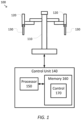
- FIG 1 is a simplified diagram of a computer-assisted system 100 according to some embodiments.
- computer-assisted system 100 includes a computer-assisted device 110 with one or more movable or articulated arms 120.
- Each of the one or more articulated arms 120 may support one or more instruments 130.
- computer-assisted device 110 may be consistent with a computer-assisted surgical device.
- the one or more articulated arms 120 may each provide support for medical instruments 130 such as surgical instruments, imaging devices, and/or the like.
- the instruments 130 may include end effectors that are capable of, but are not limited to, performing, gripping, retracting, cauterizing, ablating, suturing, cutting, stapling, fusing, sealing, etc., and/or combinations thereof.
- Computer-assisted device 110 may further be coupled to an operator workstation (not shown), which may include one or more master controls for operating the computer-assisted device 110, the one or more articulated arms 120, and/or the instruments 130.
- the one or more master controls may include master manipulators, levers, pedals, switches, keys, knobs, triggers, and/or the like.
- computer-assisted device 110 and the operator workstation may correspond to a da Vinci ® Surgical System commercialized by Intuitive Surgical, Inc. of Sunnyvale, California.
- computer-assisted surgical devices with other configurations, fewer or more articulated arms, and/or the like may be used with computer-assisted system 100.
- Computer-assisted device 110 is coupled to a control unit 140 via an interface.
- the interface may include one or more cables, fibers, connectors, and/or buses and may further include one or more networks with one or more network switching and/or routing devices.
- Control unit 140 includes a processor 150 coupled to memory 160. Operation of control unit 140 is controlled by processor 150. And although control unit 140 is shown with only one processor 150, it is understood that processor 150 may be representative of one or more central processing units, multi-core processors, microprocessors, microcontrollers, digital signal processors, field programmable gate arrays (FPGAs), application specific integrated circuits (ASICs), and/or the like in control unit 140.
- FPGAs field programmable gate arrays
- ASICs application specific integrated circuits
- Control unit 140 may be implemented as a stand-alone subsystem and/or board added to a computing device or as a virtual machine. In some embodiments, control unit 140 may be included as part of the operator workstation and/or operated separately from, but in coordination with the operator workstation.
- Memory 160 may be used to store software executed by control unit 140 and/or one or more data structures used during operation of control unit 140.
- Memory 160 may include one or more types of machine readable media. Some common forms of machine readable media may include floppy disk, flexible disk, hard disk, magnetic tape, any other magnetic medium, CD-ROM, any other optical medium, punch cards, paper tape, any other physical medium with patterns of holes, RAM, PROM, EPROM, FLASH-EPROM, any other memory chip or cartridge, and/or any other medium from which a processor or computer is adapted to read.
- control application 170 may be used to support autonomous, semiautonomous, and/or teleoperated control of computer-assisted device 110.
- Control application 170 may include one or more application programming interfaces (APIs) for receiving position, motion, force, torque, and/or other sensor information from computer-assisted device 110, articulated arms 120, and/or instruments 130, exchanging position, motion, force, torque, and/or collision avoidance information with other control units regarding other devices, and/or planning and/or assisting in the planning of motion for computer-assisted device 110, articulated arms 120, and/or instruments 130.
- APIs application programming interfaces
- control application 170 may further support autonomous, semiautonomous, and/or teleoperated control of the instruments 130 during a surgical procedure. And although control application 170 is depicted as a software application, control application 170 may be implemented using hardware, software, and/or a combination of hardware and software.
- computer-assisted system 100 may be found in an operating room and/or an interventional suite. And although computer-assisted system 100 includes only one computer-assisted device 110 with two articulated arms 120 and corresponding instruments 130, one of ordinary skill would understand that computer-assisted system 100 may include any number of computer-assisted devices with articulated arms and/or instruments of similar and/or different in design from computer-assisted device 110. In some examples, each of the computer-assisted devices may include fewer or more articulated arms and/or instruments.
- Figure 2 is a simplified diagram showing a minimally invasive surgical instrument 200 according to some embodiments.
- surgical instrument 200 may be consistent with any of the instruments 130 of Figure 1 .
- the directions "proximal” and “distal” as depicted in Figure 2 and as used herein help describe the relative orientation and location of components of surgical instrument 200.
- Distal generally refers to elements in a direction further along a kinematic chain from a base of a computer-assisted device, such as computer-assisted device 110, and/or or closest to the surgical work site in the intended operational use of the surgical instrument 200.
- Proximal generally refers to elements in a direction closer along a kinematic chain toward the base of the computer-assisted device and/or one of the articulated arms of the computer-assisted device.
- surgical instrument 200 includes a long shaft 210 used to couple an end effector 220 located at a distal end of shaft 210 to where the surgical instrument 200 is mounted to an articulated arm and/or a computer-assisted device at a proximal end of shaft 210.
- shaft 210 may be inserted through an opening (e.g., a body wall incision, a natural orifice, and/or the like) in order to place end effector 220 in proximity to a remote surgical site located within the anatomy of a patient.
- end effector 220 is generally consistent with a two-jawed gripper-style end effector, which in some embodiments may further include a cutting and/or a fusing or sealing mechanism as is described in further detail below with respect to Figures 3 and 4A-4C .
- end effector 220 is generally consistent with a two-jawed gripper-style end effector, which in some embodiments may further include a cutting and/or a fusing or sealing mechanism as is described in further detail below with respect to Figures 3 and 4A-4C .
- a cutting and/or a fusing or sealing mechanism as is described in further detail below with respect to Figures 3 and 4A-4C .
- end effector 220 is generally consistent with a two-jawed gripper-style end effector, which in some embodiments may further include a cutting and/or a fusing or sealing mechanism as is described in further detail below with respect to Figures 3 and 4A-4C .
- different surgical instruments 200 with different end effectors 220 are possible
- a surgical instrument such as surgical instrument 200 with end effector 220 typically relies on multiple degrees of freedom (DOFs) during its operation.
- DOFs degrees of freedom
- various DOFs that may be used to position, orient, and/or operate end effector 220 are possible.
- shaft 210 may be inserted in a distal direction and/or retreated in a proximal direction to provide an insertion DOF that may be used to control how deep within the anatomy of the patient that end effector 220 is placed.
- shaft 210 may be able rotate about its longitudinal axis to provide a roll DOF that may be used to rotate end effector 220.
- articulated wrist 230 may include one or more rotational joints, such as one or more roll, pitch or yaw joints that may provide one or more "roll,” “pitch,” and “yaw” DOF(s), respectively, that may be used to control an orientation of end effector 220 relative to the longitudinal axis of shaft 210.
- the one or more rotational joints may include a pitch and a yaw joint; a roll, a pitch, and a yaw joint, a roll, a pitch, and a roll joint; and/or the like.
- end effector 220 may further include a grip DOF used to control the opening and closing of the jaws of end effector 220 and/or an activation DOF used to control the extension, retraction, and/or operation of a cutting mechanism as is described in further detail below.
- Surgical instrument 200 further includes a drive system 240 located at the proximal end of shaft 210.
- Drive system 240 includes one or more components for introducing forces and/or torques to surgical instrument 200 that may be used to manipulate the various DOFs supported by surgical instrument 200.
- drive system 240 may include one or more motors, solenoids, servos, active actuators, hydraulic actuators, pneumatic actuators, and/or the like that are operated based on signals received from a control unit, such as control unit 140 of Figure 1 .
- the signals may include one or more currents, voltages, pulsewidth modulated wave forms, and/or the like.
- drive system 240 may include one or more shafts, gears, pulleys, rods, bands, and/or the like which may be coupled to corresponding motors, solenoids, servos, active actuators, hydraulics, pneumatics, and/or the like that are part of the articulated arm, such as any of the articulated arms 120, to which surgical instrument 200 is mounted.
- the one or more drive inputs such as shafts, gears, pulleys, rods, bands, and/or the like, may be used to receive forces and/or torques from the motors, solenoids, servos, active actuators, hydraulics, pneumatics, and/or the like and apply those forces and/or torques to adjust the various DOFs of surgical instrument 200.
- the forces and/or torques generated by and/or received by drive system 240 may be transferred from drive system 240 and along shaft 210 to the various joints and/or elements of surgical instrument 200 located distal to drive system 240 using one or more drive mechanisms 250.
- the one or more drive mechanisms 250 may include one or more gears, levers, pulleys, cables, rods, bands, and/or the like.
- shaft 210 is hollow and the drive mechanisms 250 pass along the inside of shaft 210 from drive system 240 to the corresponding DOF in end effector 220 and/or articulated wrist 230.
- each of the drive mechanisms 250 may be a cable disposed inside a hollow sheath or lumen in a Bowden cable like configuration.
- the cable and/or the inside of the lumen may be coated with a low-friction coating such as polytetrafluoroethylene (PTFE) and/or the like.
- PTFE polytetrafluoroethylene
- the distal end of the cable moves accordingly and applies a suitable force and/or torque to adjust one of the DOFs of end effector 220, articulated wrist 230, and/or surgical instrument 200.
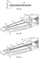
- FIG. 3 is a simplified perspective diagram of the distal end of surgical instrument 200 according to some embodiments. As shown in Figure 3 , the distal end of surgical instrument 200 is depicted so as to show additional details of end effector 220, articulated wrist 230, and drive mechanisms 250.
- end effector 220 includes opposing jaws 310 shown in an open position. Jaws 310 are configured to move between open and closed positions so that end effector 220 may be used during a procedure to grip and release tissue and/or other structures, such as sutures, located at the surgical site.
- jaws 310 may be operated together as a single unit with both jaws 310 opening and/or closing at the same time.
- jaws 310 may be opened and/or closed independently so that, for example, one jaw 310 could be held steady which the other jaw 310 may be opened and/or closed.
- Figure 3 shows that a gripping surface on an inside of each of jaws 310 includes a corresponding groove 320, which may act as a guide for a cutting blade 330, although the groove 320 may be omitted from one or more of jaws 310.
- each of the grooves 320 may aid in the alignment and/or positioning of cutting blade 330 during a cutting operation. Extraction and/or retraction of cutting blade 330 is accomplished using a drive component 340 to which cutting blade 330 is attached.
- drive component 340 pushes on cutting blade 330 to extend cutting blade 330 and pulls on cutting blade 330 to retract cutting blade 330.
- Use and positioning of cutting blade 330 is shown in Figures 4A-4C , which are simplified cut-away diagrams of end effector 220 according to some embodiments.
- Figure 4A shows the relationship between cutting blade 330 and drive component 340.
- End effector 220 further includes a garage feature 350 located at a proximal end of jaws 310.
- Garage feature 350 includes an opening through which both drive component 340 and cutting blade 330 may pass.
- Garage feature 350 is configured to provide a safe storage area for cutting blade 330 when cutting blade 330 is not in use.
- end effector 220 is configured so that cutting blade 330 may be retracted into garage feature 350 in a "garaged" or stored position in which cutting blade 330 is recessed proximally behind jaws 310 as shown in Figure 4B .
- Cutting blade 330 may additionally be extended to a position in which cutting blade 330 is positioned at or near a distal end of one of the grooves 320 as shown in Figure 4C .
- the positioning of cutting blade 330 as shown in Figure 4C may correspond to a position of cutting blade 330 during a cutting operation.
- end effector 220 and surgical instrument 200 are designed so that the default or home position of cutting blade 330 is within garage feature 350.
- This arrangement of garage feature 350 may provide several features to end effector 220.
- cutting blade 330 when cutting blade 330 is retracted into garage feature 350, the sharp cutting edge of cutting blade 330 is effectively sheathed so that cutting blade 330 is unlikely to accidentally cut tissue during a procedure and/or medical personnel handling surgical instrument 200 and/or end effector 220 before and/or after a procedure.
- cutting blade 330 when cutting blade 330 is retracted into garage feature 350, cutting blade 330 may also be protected from damage, such as accidental dulling, when cutting blade 330 is not actively being used to cut.
- the gripping surface on the inside of each of jaws 310 may further include one or more optional electrodes 360.
- electrodes 360 may be used to deliver electrosurgical energy to fuse tissue being held between jaws 310.
- electrodes 360 may provide an electro-cautery, fusing, and/or sealing feature to end effector 220 so that tissue may be cut and/or fused/sealed using the same surgical tool 200.
- operation of jaws 310, cutting blade 330, and/or the joints of articulated wrist 230 may be accomplished using corresponding ones of the drive mechanisms 250.
- a distal end of two of the drive mechanisms 250 may be coupled to a respective jaw 310 so that as the corresponding drive mechanism 250 applies a pull and/or a pushing force (for example, using a cable, lead screw, and/or the like), the respective jaw 310 may be opened and/or closed.
- both jaws 310 may be coupled to the distal end of the same drive mechanism 250.
- drive component 340 may be coupled to a distal end of a corresponding drive mechanism 250 so that forces and/or torques applied to the corresponding drive mechanism 250 may be transferred to the push and/or pull motion of drive component 340.
- additional drive mechanisms 350 may be used to operate the roll, pitch, and/or yaw DOFs in articulated wrist 230.
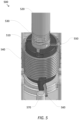
- FIG 5 is a simplified perspective diagram of a drive unit 500 for a degree of freedom according to some embodiments.
- drive unit 500 may be representative of a portion of the components in drive system 240 of Figure 2 .
- drive unit 500 is based on a rotational actuation approach in which a capstan 510 is rotated to actuate a DOF.
- Capstan 510 is coupled to a drive shaft 520 which may be the drive shaft of a motor, servo, active actuator, hydraulic actuator, pneumatic actuator, and/or the like (not shown).
- a cable 530 attached to capstan 510 and/or drive shaft 520 may be further wrapped around and/or unwrapped from around capstan 510 and/or drive shaft 520.
- cable 530 is attached to the proximal end of a corresponding drive mechanism, such as any of drive mechanisms 250, the wrapping and unwrapping of the cable may translate into corresponding pulling and pushing forces and/or torques that may be applied to a DOF of an end effector located at the distal end of the drive mechanism.
- rotation of capstan 510 and drive shaft 520 and the corresponding wrapping and/or unwrapping of cable 530 may result in opening and/or closing of gripper jaws such as jaws 310, extending and/or retracting of a cutting blade such as cutting blade 330, flexing and/or unflexing of articulated wrist joints, and/or the like.
- monitoring a rotation angle and/or rotational velocity of capstan 510 and/or drive shaft 520 may also provide an indication of a current position and/or velocity of the corresponding DOF coupled to cable 530 through the corresponding drive mechanism.
- the rotation angle and/or rotational velocity of capstan 510 and/or drive shaft 520 may provide useful feedback on the angle to which jaws 310 are opened, the position of cutting blade 330, and/or the pitch and/or yaw angle of articulated wrist 230 depending on which of the drive mechanisms 250 cable 530 is coupled.
- a drive unit such as drive unit 500 may include some type of resistive and/or restraining mechanism to return drive unit 500 to a corresponding home position.
- use of a home position for a DOF may support configuration of a surgical instrument, such as surgical instrument 200, where gripping jaws are automatically closed and/or mostly closed, cutting blades are retracted into a garage feature, articulated wrist joints are straightened, and/or the like.
- drive unit 500 includes a restraining mechanism in the form of a torsion spring 540.
- Torsion spring 540 is shown attached at one end 550 to capstan 510 and wrapped around capstan 510. As capstan 510 is rotated, a second end 560 of torsion spring 540 may freely rotate until it rotates up against a stop 570 that may be part of a body of drive unit 500. As capstan 510 continues to rotate after the second end 560 of torsion spring 540 is against stop 570, torsion spring 540 will begin to provide a restraining and/or return to home force and/or torque to capstan 510 as dictated by the amount of rotation of capstan 510 and a spring constant of torsion spring 540.
- torsion spring 540 applies increasing return to home force and/or torque to capstan 510. It is this return to home force and/or torque on capstan 510 that may be used, for example, to close the gripping jaws, retract the cutting blade, and/or straighten the articulated wrist joints.
- Figure 5 shows the restraining mechanism as a torsion spring wrapped around capstan 510, one of ordinary skill would recognize other possible restraining mechanisms and/or configurations for the restraining mechanisms to accomplish a similar restraining/return to home function.
- the body of drive unit 500 may further include a second stop to provide a return to home force and/or torque to capstan 510 in an opposite direction to the return to home force and/or torque resulting from stop 570.
- the second end 560 of torsion spring 540 may be mounted to the body of drive unit 500 so that no free movement of torsion spring 540 is permitted before torsion spring 540 begins applying return to home force and/or torque to capstan 510 and/or torsion spring 540 applies at least some return to home force and/or torque to capstan 510 even without rotation of capstan 510.
- selection of an appropriately sized restraining mechanism such as the spring constant for torsion spring 540, for a DOF of an end effector may present several challenges to the designer of a surgical instrument. In some situations it may be desirable to select the size of the restraining mechanism to overcome any likely and/or reasonable interference with the desired return to home function of the corresponding drive unit of the DOF. In some examples, selection of the size of the restraining mechanism to overcome any likely and/or reasonable interference tends to oversize the restraining mechanism for many of the possible operational scenarios. Additionally, as the size of the restraining mechanism increases, a corresponding greater force or torque has to be applied to the drive unit to overcome the restraining mechanism.
- this may include the use of a larger motor, solenoid, servo, active actuator, hydraulic actuator, pneumatic actuator, and/or the like to overcome the restraining mechanism or result in a smaller operational margin for the DOF that results in less force and/or torque being available to drive the DOF to perform an operation. For example, less cutting force and/or torque may be available to apply to a cutting blade to perform a cut. In some examples, this larger return to home force and/or torque may increase the stress and/or strain placed on the drive mechanism that may result in increased wear on the drive mechanism, stretching of the drive mechanism, and/or the like.
- the stretching of the drive mechanism may result in the drive mechanism and the corresponding DOF becoming out of tolerance, thus resulting is a diminished ability to control the DOF as desired.
- this larger return to home force and/or torque may increase the likelihood of injury to a patient and/or medical personnel, such as when a return to home gripping force may result in damage and/or tearing of tissue still located between the gripping jaws of an end effector.
- One possible compromise is to size the restraining mechanism to provide sufficient return to home force and/or torque to return the DOF to the home position when the surgical instrument is not being used (i.e., when the surgical instrument is not mounted to a corresponding articulated arm and/or computer-assisted device) and to use the motor, solenoid, servo, active actuator, hydraulic actuator, pneumatic actuator, and/or the like coupled to the drive unit to provide additional return to home force and/or torque during operational scenarios where additional return to home force and/or torque is desired.
- the restraining mechanism may be sized to provide approximately 0 N to 10 N of return to home force and/or a similar torque to the DOF.
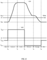
- FIG. 6 is a simplified diagram of a positional profile 610 and a corresponding torque limit profile 620 for a cutting operation according to some embodiments.
- positional profile 610 and torque limit profile 620 may be suitable for application to cutting blade 330 using drive unit 500.
- positional profile 610 and torque limit profile 620 include a four-phase cutting operation beginning at a time t 0 .
- the four phases include an extending phase from t 0 to t 1 , a holding phase from t 1 to t 2 , a retracting phase from t 2 to t 3 , and a garaging phase from t 3 to t 4 .
- the position of the cutting blade will be described relative to an x position of the cutting blade with more positive positions being in a distal direction, however, one of ordinary skill would understand that the positions for the cutting blade may be represented using any suitable positional and/or rotational axis such as a position along an axis defined by groove 320, a rotational angle of capstan 510, and/or the like and/or could alternatively be characterized with positive values in a more proximal direction.
- x RET may correspond to a garaged and/or home position of the cutting blade.
- the zero position for the cutting blade may correspond to an outer or distal edge of a garage feature, such as garage feature 350, when the articulated wrist is in a straight or unflexed position.
- x RET is selected as a sufficiently negative value, such as approximately -3 mm, to account for variability among different drive mechanisms and/or drive units.
- a negative x RET may also address possible deviations in the drive mechanism caused by the flexing of the articulated wrist in the surgical instrument.
- the drive mechanism may be subject to bending and/or movement within the hollow shaft (e.g., shaft 210) of the surgical instrument. As the drive mechanism bends and/or moves an effective distance, as seen by the drive mechanism, may change between the distal end at the cutting blade and the proximal end at the drive unit. As a result, the amount of retraction to return the cutting blade to the garage may vary between situations where the articulated wrist is flexed and unflexed.
- x EXT may correspond to a fully and/or mostly extended position for the cutting blade, such as approximately +18 mm, so that the cutting blade does not strike the end of a guiding groove, such as one of the grooves 320, and/or to reduce the likelihood of cutting blade exposure where the cutting blade comes out of the guiding grooves and is not able to be retracted back into the garaged or home position.
- a duration of the extending phase i.e., the time between t 0 and t 1
- One of the goals of the holding phase is to continue to command the cutting blade to full extension at x EXT to account for operational scenarios when it takes longer than the duration of the extending phase for the cutting blade to transition from x RET to x EXT .
- the holding phase may also reduce the likelihood that the cutting blade will be retracted before it has reached the desired extension.
- a duration of the holding phase i.e., the time between t 1 and t 2
- Retraction of the cutting blade may occur using a two-phase operation that includes the retracting phase and the garaging phase.
- One of the goals of the retracting phase is to rapidly retract the cutting blade to a position x HLD that corresponds to retracting the cutting blade to a hold position that is most of the way back to the garaged or home position, such as approximately +1 mm.
- the cutting blade is more completely retracted to the x RET position during the garaging phase.
- the use of the two-phase operation of retracting followed by garaging may reduce the likelihood that the cutting blade may rebound back out the garage during retraction relative to a single-phase operation directly to x RET and/or reduce the magnitude of loads applied to the cutting blade and drive mechanism during the garaging phase.
- a duration of the retracting phase (i.e., the time between t 2 and t 3 ) may vary, for example, from 50 ms to 175 ms in length, and preferably 120 ms in length.
- a duration of the garaging phase (i.e., the time between t 3 and t 4 ) may vary, for example, from 75 ms to 200 ms in length, and preferably 150 ms in length.
- the time periods before t 0 , when the cutting operation begins, and after t 4 , when the cutting operation ends, may correspond to idle phases where the cutting blade is held at the garaged or home position of x RET using force and/or torque provided by both the restraining mechanism of the drive unit and the motor, solenoid, servo, active actuator, hydraulic actuator, pneumatic actuator, and/or the like used to operate the drive unit as is discussed further below.
- the positional profile 610 of Figure 6 represents a desired position of the cutting blade during a cutting operation.
- positional profile 610 may be converted to a time sequence of position commands for the cutting blade and the motor, solenoid, server actuator, hydraulic actuator, pneumatic actuator, and/or the like used to actuate the drive unit for the cutting blade.
- interpolation and/or curve fitting using, for example, a cubic spline may be used to determine the time sequence of position commands so as to provide a smooth positional profile 610 or position trajectory for the cutting blade throughout the cutting operation.
- the actual position of the cutting blade and/or the drive unit may be monitored during the cutting operation using one or more sensors to determine whether the cutting blade and/or the drive unit are able to follow the positional profile 610.
- an audio, visual, and/or textual alert may be provided to the surgeon and/or other medical personnel to indicate that the cutting operation may not have been successful.
- the cutting operation may not be successful when the cutting blade is not able to extend to x EXT and/or becomes exposed and cannot return to x RET .
- the control unit for the motor, solenoid, servo, active actuator, hydraulic actuator, pneumatic actuator, and/or the like driving the drive unit for the cutting blade may be subject to upper and/or lower force and/or torque limits.
- the force and/or torque limits may be determined based on the size of the motor, solenoid, servo, active actuator, hydraulic actuator, pneumatic actuator, and/or the like, to reduce the likelihood of damage and/or excessive wear to the drive unit, drive mechanism, and/or cutting blade, to reduce power used to actuate the cutting blade, and/or to address the practical needs of the cutting operation.
- Torque limit profile 620 represents one possible such profile and, although torque limit profile 620 is described in terms of torques, other control actuators and/or control systems may alternatively use limits to voltage, current, force, duty cycle, and/or the like as would be understood by one of ordinary skill in the art.
- torque limit profile 620 uses a combination of three torque limits depending upon which phase of the cutting operation the cutting blade is in and/or whether the cutting blade is currently idle. And although the torque limits are characterized with a positive torque limit value corresponding to an extending direction, one of ordinary skill would understand that the sign of the torque limit is arbitrary depending on the configuration of the control actuators and/or the drive unit for the cutting blade. In torque limit profile 620, a torque limit of T EXT is used during the extending and holding phases of the cutting operation.
- T EXT is set at a sufficiently high limit to overcome any restraining mechanism, such as torsion spring 540, in the drive unit and to supply suitable actuating force and/or torque to allow the cutting blade to cut tissue while the cutting blade is being extended.
- T EXT may be in a range suitable for the cutting blade to deliver 15 N to 20 N of cutting force during extension.
- T RET is set at a sufficiently high limit to overcome any tissue and/or other debris from the cutting operation that may interfere with the desired retraction and/or garaging of the cutting blade after cutting has taken place.
- T RET may have approximately the same magnitude as T EXT , but with an opposite sign so that T RET may be in a range suitable for delivering 15 N to 20 N of retracting force to the cutting blade.
- T RET may have a magnitude smaller than that of T EXT to account for the torque used to overcome the restraining mechanism during extension and to reflect the assistance provided by the restraining mechanism during retraction.
- T IDLE is used when the cutting blade is idle.
- T IDLE is set to a lower magnitude than T RET , but with a magnitude sufficient to assist the restraining mechanism in keeping the cutting blade garaged during periods of non-use.
- the magnitude of T IDLE may be set to avoid placing excessive strain on the motor, solenoid, servo, active actuator, hydraulic actuator, pneumatic actuator, drive mechanism, drive, unit, etc. due to attempts to retract the cutting blade beyond any physical limits imposed by the end effector and/or garage feature due to the negative retraction position of x RET .
- T IDLE may be in a range suitable for delivering 0 N to 5 N of retracting force to the cutting blade.
- Figure 6 is merely an example which should not unduly limit the scope of the claims.
- different positional and/or torque limit profiles are possible depending upon the desired operation of a particular DOF, such as the cutting DOF more directly discussed in Figure 6 .
- different torque limit values may be used in the extending and holding phases and/or in the retracting and garaging phases.
- a more complex torque limit profile using ramps and/or the like are possible.
- the torque limit may be variable based on the current position of the cutting blade.
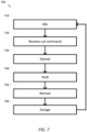
- Figure 7 is a simplified diagram of a method 700 for performing a cutting operation according to some embodiments.
- One or more of the processes 710-760 of method 700 may be implemented, at least in part, in the form of executable code stored on non-transient, tangible, machine readable media that when run by one or more processors (e.g., the processor 150 in control unit 140) may cause the one or more processors to perform one or more of the processes 710-760.
- method 700 may be performed by an application, such as control application 170.
- method 700 may be used to extend and retract a cutting blade, such as cutting blade 330, of a surgical instrument, such as surgical instrument 200.
- the cutting operation of method 700 may be performed according to positional profile 610 and/or torque limit profile 620.
- drive components such as those described in Figures 2, 3 , and 4A-4C may be used during the performance of method 700 to extend, retract, and/or maintain the cutting blade in an idle position.
- a cutting blade is maintained in an idle position.
- the idle position may correspond to a garaged and/or home position where the cutting blade is protected from damage and/or the cutting blade is sheathed within a garage feature, such as garage feature 350, so as to reduce the likelihood of accidentally cutting tissue and/or medical personnel when active cutting is not taking place.
- the idle position may correspond to a slightly negative position, such as the position x RET of positional profile 610.
- the cutting blade may be held in the idle position based on force and/or torque applied to the cutting blade by a drive component, a drive mechanism, a drive unit, and/or an actuator such as a motor, solenoid, servo, active actuator, hydraulic actuator, pneumatic actuator, and/or the like.
- the applied force and/or torque may be applied using a restraining mechanism, such as torsion spring 540, the actuator, and/or both.
- the amount of force and/or torque applied by the actuator may be subject to a limit, such as T IDLE from torque limit profile 620. In some examples, as long as the cutting blade is not being used for cutting the cutting blade may be maintained in the idle position.
- process 710 may correspond to the periods labeled as idle periods in Figure 6 .
- a cut command is received.
- a surgeon and/or other personnel may request that a cutting operation take place.
- the cutting operation may be requested using one or more master controls, such as one or more master manipulators, levers, pedals, switches, keys, knobs, triggers, and/or the like located on an operator console.
- the requested cutting operation may be received by a control application, such as control application 170, via an interrupt, an input polling operation, an API call, and/or the like.
- a first phase of the cutting operation may include actuating the cutting blade to rapidly extend from the idle position of process to 710 to an extended position, such as the position x EXT of positional profile 610.
- the actuation of the cutting blade during process 730 may include providing a time sequence of position commands to the drive unit operating the DOF associated with the cutting blade so that a smooth positional profile, such as positional profile 610 during the extending phase, is commanded for the cutting blade.
- the cutting blade may be extended based on force and/or torque applied to the cutting blade by a drive component, a drive mechanism, a drive unit, and/or an actuator such as a motor, solenoid, servo, active actuator, hydraulic actuator, pneumatic actuator, and/or the like.
- the amount of force and/or torque applied to the cutting blade may be selected so as to overcome any restraining mechanism used to keep the cutting blade in the idle position as well as to deliver sufficient cutting force to cut tissue.
- the amount of force and/or torque applied may be subject to a limit, such as T EXT from torque limit profile 620.
- process 730 may correspond to the period labeled as the extending period in Figure 6 .
- a second phase of the cutting operation may include continuing to actuate the cutting blade to extend to the extended position of process 730.
- this extended position may correspond to the position x EXT of positional profile 610.
- the cutting blade may continue to be extended and/or held at the extended position based on force and/or torque applied to the cutting blade by a drive component, a drive mechanism, a drive unit, and/or an actuator such as a motor, solenoid, servo, active actuator, hydraulic actuator, pneumatic actuator, and/or the like.
- the amount of force and/or torque applied to the cutting blade may be selected so as to overcome any restraining mechanism used to keep the cutting blade in the idle position as well as to deliver sufficient cutting force to cut tissue.
- the amount of force and/or torque applied may be subject to a limit, such as T EXT from torque limit profile 620.
- process 740 may correspond to the period labeled as the hold period in Figure 6 .
- a third phase of the cutting operation may include actuating the cutting blade to rapidly retract from the extended position of processes 730 and/or 740 to a hold position, such as the position x HLD of positional profile 610, located most of the way back toward the idle position of process 710.
- the actuation of the cutting blade during process 750 may include providing a time sequence of position commands to the drive unit operating the DOF associated with the cutting blade so that a smooth positional profile, such as positional profile 610 during the retracting phase, is commanded for the cutting blade.
- the cutting blade may be retracted based on force and/or torque applied to the cutting blade by a drive component, a drive mechanism, a drive unit, and/or an actuator such as a motor, solenoid, servo, active actuator, hydraulic actuator, pneumatic actuator, and/or the like.
- the amount of force and/or torque applied to the cutting blade may be selected so as to overcome any likely tissue, debris, and/or the like that may be interfering with retraction of the cutting blade.
- the retracting may additionally be aided by a restraining mechanism used to keep the cutting blade in the idle position.
- the amount of force and/or torque applied may be subject to a limit, such as T RET from torque limit profile 620.
- process 750 may correspond to the period labeled as the retracting period in Figure 6 .
- a fourth phase of the cutting operation may include actuating the cutting blade to retract from the hold position of process 750 to the idle position of process 710.
- the actuation of the cutting blade during process 760 may include providing a time sequence of position commands to the drive unit operating the DOF associated with the cutting blade so that a smooth positional profile, such as positional profile 610 during the garaging phase, is commanded for the cutting blade.
- the cutting blade may be retracted based on force and/or torque applied to the cutting blade by a drive component, a drive mechanism, a drive unit, and/or an actuator such as a motor, solenoid, servo, active actuator, hydraulic actuator, pneumatic actuator, and/or the like.
- the amount of force and/or torque applied to the cutting blade may be selected so as to overcome any likely tissue, debris, and/or the like that may be interfering with garaging of the cutting blade.
- the garaging may additionally be aided by a restraining mechanism used to keep the cutting blade in the idle position.
- the amount of force and/or torque applied may be subject to a limit, such as T RET from torque limit profile 620.
- process 760 may correspond to the period labeled as the garaging period in Figure 6 .
- method 700 may be performed in cooperation with one or more monitoring and/or reporting processes.
- the actual position of the cutting blade and/or the drive unit for the cutting blade may be monitored using one or more sensors during method 700 to determine whether the cutting blade and/or the drive unit are able to follow the positional profile for the cutting blade, such as the positional profile 610.
- an audio, visual, and/or textual alert may be provided to the surgeon and/or other medical personnel to indicate that the cutting operation may not have been successful.
- the cutting operation may not be successful when the cutting blade is not able to extend as commanded during processes 730 and/or 740. In some examples, the cutting operation may not be successful when the cutting blade becomes exposed and cannot return to the garage. In some examples, a warning and/or an alert using one or more audio, visual, and/or textual alerts may be issued when any of the extracting, holding, retracting, and/or garaging operations reach one of the force and/or torque limits corresponding to the respective cutting operation phase.
- control unit 140 may include non-transient, tangible, machine readable media that include executable code that when run by one or more processors (e.g., processor 150) may cause the one or more processors to perform the processes of method 700.
- processors e.g., processor 150
- Some common forms of machine readable media that may include the processes of method 700 are, for example, floppy disk, flexible disk, hard disk, magnetic tape, any other magnetic medium, CD-ROM, any other optical medium, punch cards, paper tape, any other physical medium with patterns of holes, RAM, PROM, EPROM, FLASH-EPROM, any other memory chip or cartridge, and/or any other medium from which a processor or computer is adapted to read.
Claims (13)
- Instrument chirurgical de coupe (130, 200) destiné à une utilisation avec un dispositif assisté par ordinateur, l'instrument comprenant :une unité d'entraînement (240, 500) comprenant un mécanisme de retenue et un ou plusieurs moteurs, solénoïdes, servomécanismes, actionneurs actifs, actionneurs hydrauliques ou actionneurs pneumatiques ;un effecteur terminal (220) situé à une extrémité distale de l'instrument (130, 200), l'effecteur terminal (220) comprenant des mâchoires de préhension opposables (310) et une lame de coupe (330) ;une tige (210) entre l'unité d'entraînement (240, 500) et l'effecteur terminal (220), la tige (210) abritant un ou plusieurs mécanismes d'entraînement (250) pour coupler une force ou un couple provenant de l'unité d'entraînement (240, 500) à l'effecteur terminal (220) ;un logement (350) pour abriter la lame de coupe (330) lorsque la lame de coupe (330) n'est pas en cours d'utilisation ; etune unité de commande ;dans lequel pour réaliser une opération de coupe, l'unité de commande est configurée pour :déployer, à l'aide des un ou plusieurs moteurs, solénoïdes, servomécanismes, actionneurs actifs, actionneurs hydrauliques, ou actionneurs pneumatiques, la lame de coupe (330) en la faisant passer d'une première position à une deuxième position ;rétracter, à l'aide des un ou plusieurs moteurs, solénoïdes, servomécanismes, actionneurs actifs, actionneurs hydrauliques, ou actionneurs pneumatiques, la lame de coupe (330) en la faisant passer de la deuxième position à une troisième position entre les première et deuxième positions ; etrétracter davantage, à l'aide des un ou plusieurs moteurs, solénoïdes, servomécanismes, actionneurs actifs, actionneurs hydrauliques ou actionneurs pneumatiques, la lame de coupe (330) jusqu'à la première position ;dans lequel :lorsque la lame de coupe (330) n'est pas en cours d'utilisation, la lame de coupe (330) est maintenue dans la première position à l'aide du mécanisme de retenue ou à la fois du mécanisme de retenue et de la force ou du couple appliqué(e) par les un ou plusieurs moteurs, solénoïdes, servomécanismes, actionneurs actifs, actionneurs hydrauliques ou actionneurs pneumatiques ;un premier ordre de grandeur des limites de force ou de couple appliquées pour les un ou plusieurs moteurs, solénoïdes, servomécanismes, actionneurs actifs, actionneurs hydrauliques ou actionneurs pneumatiques lorsque la lame de coupe (330) est en cours de déploiement est supérieur à un deuxième ordre de grandeur des limites de force ou de couple lorsque la lame de coupe (330) est en train d'être rétractée puis rétractée davantage ; etune différence entre les premier et deuxième ordres de grandeur est basée sur une force ou un couple appliqué(e) par le mécanisme de retenue.
- Instrument selon la revendication 1, dans lequel le mécanisme de retenue est un ressort (540).
- Instrument selon la revendication 1, comprenant en outre un poignet articulé (230) couplant l'effecteur terminal (220) à la tige (210).
- Instrument selon la revendication 3, dans lequel un degré de rétraction pour rétracter davantage la lame de coupe (330) varie selon que le poignet articulé (230) est fléchi ou non fléchi.
- Instrument selon la revendication 1, dans lequel une ou plusieurs des mâchoires de préhension (310) comportent une gorge (320) pour aider à guider la lame de coupe (330) lors du déploiement et de la rétraction.
- Instrument selon la revendication 1, dans lequel la première position se trouve à l'intérieur du logement (350) .
- Instrument selon la revendication 6, dans lequel la troisième position correspond à une position dans laquelle la lame de coupe (330) est rétractée jusqu'à se trouver juste à l'extérieur du logement (350).
- Instrument selon la revendication 1, dans lequel l'unité de commande est en outre configurée pour maintenir la lame de coupe (330) dans la deuxième position avant de rétracter la lame de coupe (330) jusqu'à la troisième position.
- Instrument selon la revendication 8, dans lequel les limites de force ou de couple pour les un ou plusieurs moteurs, solénoïdes, servomécanismes, actionneurs actifs, actionneurs hydrauliques, ou actionneurs pneumatiques lorsque la lame de coupe (330) est en cours de déploiement sont les mêmes que les limites de force ou de couple lorsque la lame de coupe (330) est maintenue déployée.
- Instrument selon la revendication 1, dans lequel, au cours de l'opération de coupe, la lame de coupe (330) reçoit une commande lui demandant de suivre un profil de positionnement, le profil de positionnement comprenant une séquence temporelle de positions souhaitées pour la lame de coupe (330) et les un ou plusieurs moteurs, solénoïdes, servomécanismes, actionneurs actifs, actionneurs hydrauliques, ou actionneurs pneumatiques décrivant une trajectoire lisse pour la lame de coupe (330) entre les première, deuxième et troisième positions.
- Instrument selon la revendication 1, dans lequel un ordre de grandeur des limites de force ou de couple lorsque la lame de coupe (330) est maintenue dans la première position est inférieur à un ordre de grandeur des limites de force ou de couple lorsque la lame de coupe (330) est en cours de déploiement ou de rétraction.
- Instrument selon la revendication 1, dans lequel les limites de force ou de couple lorsque la lame de coupe (330) est en cours de rétraction jusqu'à la troisième position sont les mêmes que les limites de force ou de couple lorsque la lame de coupe (330) est en train d'être rétractée davantage jusqu'à la première position.
- Instrument selon la revendication 1, dans lequel l'unité de commande est en outre configurée pour maintenir la lame de coupe (330) dans la troisième position avant de rétracter davantage la lame de coupe (330) jusqu'à la première position.
Priority Applications (1)
| Application Number | Priority Date | Filing Date | Title |
|---|---|---|---|
| EP23181552.3A EP4233742A3 (fr) | 2015-05-15 | 2016-05-13 | Système pour l'utilisation d'un instrument de coupe mini-invasif |
Applications Claiming Priority (2)
| Application Number | Priority Date | Filing Date | Title |
|---|---|---|---|
| US201562162217P | 2015-05-15 | 2015-05-15 | |
| PCT/US2016/032351 WO2016187006A1 (fr) | 2015-05-15 | 2016-05-13 | Système et méthode pour une opération à instrument de coupe non effractif |
Related Child Applications (1)
| Application Number | Title | Priority Date | Filing Date |
|---|---|---|---|
| EP23181552.3A Division EP4233742A3 (fr) | 2015-05-15 | 2016-05-13 | Système pour l'utilisation d'un instrument de coupe mini-invasif |
Publications (3)
| Publication Number | Publication Date |
|---|---|
| EP3294186A1 EP3294186A1 (fr) | 2018-03-21 |
| EP3294186A4 EP3294186A4 (fr) | 2019-01-09 |
| EP3294186B1 true EP3294186B1 (fr) | 2023-07-26 |
Family
ID=57320308
Family Applications (2)
| Application Number | Title | Priority Date | Filing Date |
|---|---|---|---|
| EP16797006.0A Active EP3294186B1 (fr) | 2015-05-15 | 2016-05-13 | Système pour l'utilisation d'un instrument de coupe mini-invasif |
| EP23181552.3A Pending EP4233742A3 (fr) | 2015-05-15 | 2016-05-13 | Système pour l'utilisation d'un instrument de coupe mini-invasif |
Family Applications After (1)
| Application Number | Title | Priority Date | Filing Date |
|---|---|---|---|
| EP23181552.3A Pending EP4233742A3 (fr) | 2015-05-15 | 2016-05-13 | Système pour l'utilisation d'un instrument de coupe mini-invasif |
Country Status (6)
| Country | Link |
|---|---|
| US (3) | US10874465B2 (fr) |
| EP (2) | EP3294186B1 (fr) |
| JP (3) | JP6499320B2 (fr) |
| KR (2) | KR102077076B1 (fr) |
| CN (2) | CN112353490A (fr) |
| WO (1) | WO2016187006A1 (fr) |
Families Citing this family (59)
| Publication number | Priority date | Publication date | Assignee | Title |
|---|---|---|---|---|
| US11229472B2 (en) | 2001-06-12 | 2022-01-25 | Cilag Gmbh International | Modular battery powered handheld surgical instrument with multiple magnetic position sensors |
| US9089360B2 (en) | 2008-08-06 | 2015-07-28 | Ethicon Endo-Surgery, Inc. | Devices and techniques for cutting and coagulating tissue |
| US8663220B2 (en) | 2009-07-15 | 2014-03-04 | Ethicon Endo-Surgery, Inc. | Ultrasonic surgical instruments |
| US11090104B2 (en) | 2009-10-09 | 2021-08-17 | Cilag Gmbh International | Surgical generator for ultrasonic and electrosurgical devices |
| US8469981B2 (en) | 2010-02-11 | 2013-06-25 | Ethicon Endo-Surgery, Inc. | Rotatable cutting implement arrangements for ultrasonic surgical instruments |
| US9439668B2 (en) | 2012-04-09 | 2016-09-13 | Ethicon Endo-Surgery, Llc | Switch arrangements for ultrasonic surgical instruments |
| US20140005705A1 (en) | 2012-06-29 | 2014-01-02 | Ethicon Endo-Surgery, Inc. | Surgical instruments with articulating shafts |
| US9393037B2 (en) | 2012-06-29 | 2016-07-19 | Ethicon Endo-Surgery, Llc | Surgical instruments with articulating shafts |
| US9351754B2 (en) | 2012-06-29 | 2016-05-31 | Ethicon Endo-Surgery, Llc | Ultrasonic surgical instruments with distally positioned jaw assemblies |
| US9226767B2 (en) | 2012-06-29 | 2016-01-05 | Ethicon Endo-Surgery, Inc. | Closed feedback control for electrosurgical device |
| US9198714B2 (en) | 2012-06-29 | 2015-12-01 | Ethicon Endo-Surgery, Inc. | Haptic feedback devices for surgical robot |
| US9326788B2 (en) | 2012-06-29 | 2016-05-03 | Ethicon Endo-Surgery, Llc | Lockout mechanism for use with robotic electrosurgical device |
| US9408622B2 (en) | 2012-06-29 | 2016-08-09 | Ethicon Endo-Surgery, Llc | Surgical instruments with articulating shafts |
| US9095367B2 (en) | 2012-10-22 | 2015-08-04 | Ethicon Endo-Surgery, Inc. | Flexible harmonic waveguides/blades for surgical instruments |
| US20140135804A1 (en) | 2012-11-15 | 2014-05-15 | Ethicon Endo-Surgery, Inc. | Ultrasonic and electrosurgical devices |
| GB2521228A (en) | 2013-12-16 | 2015-06-17 | Ethicon Endo Surgery Inc | Medical device |
| US9554854B2 (en) | 2014-03-18 | 2017-01-31 | Ethicon Endo-Surgery, Llc | Detecting short circuits in electrosurgical medical devices |
| US10092310B2 (en) | 2014-03-27 | 2018-10-09 | Ethicon Llc | Electrosurgical devices |
| US9737355B2 (en) | 2014-03-31 | 2017-08-22 | Ethicon Llc | Controlling impedance rise in electrosurgical medical devices |
| US9913680B2 (en) * | 2014-04-15 | 2018-03-13 | Ethicon Llc | Software algorithms for electrosurgical instruments |
| US10285724B2 (en) | 2014-07-31 | 2019-05-14 | Ethicon Llc | Actuation mechanisms and load adjustment assemblies for surgical instruments |
| US10245095B2 (en) | 2015-02-06 | 2019-04-02 | Ethicon Llc | Electrosurgical instrument with rotation and articulation mechanisms |
| EP3294186B1 (fr) | 2015-05-15 | 2023-07-26 | Intuitive Surgical Operations, Inc. | Système pour l'utilisation d'un instrument de coupe mini-invasif |
| US10898256B2 (en) | 2015-06-30 | 2021-01-26 | Ethicon Llc | Surgical system with user adaptable techniques based on tissue impedance |
| US10034704B2 (en) | 2015-06-30 | 2018-07-31 | Ethicon Llc | Surgical instrument with user adaptable algorithms |
| US11051873B2 (en) | 2015-06-30 | 2021-07-06 | Cilag Gmbh International | Surgical system with user adaptable techniques employing multiple energy modalities based on tissue parameters |
| US11129669B2 (en) | 2015-06-30 | 2021-09-28 | Cilag Gmbh International | Surgical system with user adaptable techniques based on tissue type |
| US11141213B2 (en) | 2015-06-30 | 2021-10-12 | Cilag Gmbh International | Surgical instrument with user adaptable techniques |
| US10751108B2 (en) | 2015-09-30 | 2020-08-25 | Ethicon Llc | Protection techniques for generator for digitally generating electrosurgical and ultrasonic electrical signal waveforms |
| US10595930B2 (en) | 2015-10-16 | 2020-03-24 | Ethicon Llc | Electrode wiping surgical device |
| US11229471B2 (en) | 2016-01-15 | 2022-01-25 | Cilag Gmbh International | Modular battery powered handheld surgical instrument with selective application of energy based on tissue characterization |
| US10779849B2 (en) | 2016-01-15 | 2020-09-22 | Ethicon Llc | Modular battery powered handheld surgical instrument with voltage sag resistant battery pack |
| US11129670B2 (en) | 2016-01-15 | 2021-09-28 | Cilag Gmbh International | Modular battery powered handheld surgical instrument with selective application of energy based on button displacement, intensity, or local tissue characterization |
| US10555769B2 (en) | 2016-02-22 | 2020-02-11 | Ethicon Llc | Flexible circuits for electrosurgical instrument |
| US10456193B2 (en) | 2016-05-03 | 2019-10-29 | Ethicon Llc | Medical device with a bilateral jaw configuration for nerve stimulation |
| US10869682B2 (en) * | 2016-07-08 | 2020-12-22 | Covidien Lp | Cutting mechanisms for surgical end effector assemblies, instruments, and systems |
| US10376305B2 (en) | 2016-08-05 | 2019-08-13 | Ethicon Llc | Methods and systems for advanced harmonic energy |
| US11266430B2 (en) | 2016-11-29 | 2022-03-08 | Cilag Gmbh International | End effector control and calibration |
| US20200305910A1 (en) * | 2019-03-29 | 2020-10-01 | Gyrus Acmi, Inc. D/B/A Olympus Surgical Thechnologies America | Forceps including rotationally locked shafts |
| CN110051410B (zh) * | 2019-05-15 | 2022-02-22 | 成都五义医疗科技有限公司 | 一种可拆洗重用的细长轴组件及其手术器械 |
| GB2590593B (en) * | 2019-10-28 | 2023-09-13 | Cmr Surgical Ltd | Controlling a surgical instrument |
| US11786291B2 (en) | 2019-12-30 | 2023-10-17 | Cilag Gmbh International | Deflectable support of RF energy electrode with respect to opposing ultrasonic blade |
| US11660089B2 (en) | 2019-12-30 | 2023-05-30 | Cilag Gmbh International | Surgical instrument comprising a sensing system |
| US11779329B2 (en) | 2019-12-30 | 2023-10-10 | Cilag Gmbh International | Surgical instrument comprising a flex circuit including a sensor system |
| US11707318B2 (en) | 2019-12-30 | 2023-07-25 | Cilag Gmbh International | Surgical instrument with jaw alignment features |
| US11696776B2 (en) | 2019-12-30 | 2023-07-11 | Cilag Gmbh International | Articulatable surgical instrument |
| US11911063B2 (en) | 2019-12-30 | 2024-02-27 | Cilag Gmbh International | Techniques for detecting ultrasonic blade to electrode contact and reducing power to ultrasonic blade |
| US11779387B2 (en) | 2019-12-30 | 2023-10-10 | Cilag Gmbh International | Clamp arm jaw to minimize tissue sticking and improve tissue control |
| US11937866B2 (en) | 2019-12-30 | 2024-03-26 | Cilag Gmbh International | Method for an electrosurgical procedure |
| US11937863B2 (en) | 2019-12-30 | 2024-03-26 | Cilag Gmbh International | Deflectable electrode with variable compression bias along the length of the deflectable electrode |
| US11812957B2 (en) | 2019-12-30 | 2023-11-14 | Cilag Gmbh International | Surgical instrument comprising a signal interference resolution system |
| US11452525B2 (en) | 2019-12-30 | 2022-09-27 | Cilag Gmbh International | Surgical instrument comprising an adjustment system |
| US20210196359A1 (en) | 2019-12-30 | 2021-07-01 | Ethicon Llc | Electrosurgical instruments with electrodes having energy focusing features |
| US11950797B2 (en) | 2019-12-30 | 2024-04-09 | Cilag Gmbh International | Deflectable electrode with higher distal bias relative to proximal bias |
| US11786294B2 (en) | 2019-12-30 | 2023-10-17 | Cilag Gmbh International | Control program for modular combination energy device |
| US11944366B2 (en) | 2019-12-30 | 2024-04-02 | Cilag Gmbh International | Asymmetric segmented ultrasonic support pad for cooperative engagement with a movable RF electrode |
| US11723716B2 (en) | 2019-12-30 | 2023-08-15 | Cilag Gmbh International | Electrosurgical instrument with variable control mechanisms |
| CN111227947B (zh) * | 2020-02-21 | 2021-11-05 | 上海微创医疗机器人(集团)股份有限公司 | 一种手术器械、手术器械系统及手术机器人 |
| US20220054190A1 (en) * | 2020-08-20 | 2022-02-24 | Covidien Lp | End effector assembly for use in a robotic surgical instrument |
Citations (3)
| Publication number | Priority date | Publication date | Assignee | Title |
|---|---|---|---|---|
| US20100274244A1 (en) * | 2009-04-24 | 2010-10-28 | Tyco Healthcare Group Lp | Electrosurgical Tissue Sealer and Cutter |
| WO2012112888A2 (fr) * | 2011-02-18 | 2012-08-23 | Intuitive Surgical Operations, Inc. | Instrument chirurgical de fusion et découpe et procédés associés |
| WO2012166815A1 (fr) * | 2011-05-31 | 2012-12-06 | Intuitive Surgical Operations, Inc | Instrument chirurgical à commande pour état défectueux détecté |
Family Cites Families (21)
| Publication number | Priority date | Publication date | Assignee | Title |
|---|---|---|---|---|
| JPS60132550A (ja) | 1983-12-22 | 1985-07-15 | オリンパス光学工業株式会社 | 高周波切開切除具 |
| US8123764B2 (en) * | 2004-09-20 | 2012-02-28 | Endoevolution, Llc | Apparatus and method for minimally invasive suturing |
| WO2006034209A2 (fr) * | 2004-09-20 | 2006-03-30 | Suturtek Incorporated | Appareil et procede de suture a invasivite minimale |
| US7540872B2 (en) | 2004-09-21 | 2009-06-02 | Covidien Ag | Articulating bipolar electrosurgical instrument |
| US7615060B2 (en) * | 2005-06-13 | 2009-11-10 | Ethicon-Endo Surgery, Inc. | Endoscopic suturing device |
| US9179912B2 (en) | 2008-02-14 | 2015-11-10 | Ethicon Endo-Surgery, Inc. | Robotically-controlled motorized surgical cutting and fastening instrument |
| US9259274B2 (en) | 2008-09-30 | 2016-02-16 | Intuitive Surgical Operations, Inc. | Passive preload and capstan drive for surgical instruments |
| EP2679175A1 (fr) * | 2009-10-09 | 2014-01-01 | Ethicon Endo-Surgery, Inc. | Instrument chirurgical |
| US10172669B2 (en) * | 2009-10-09 | 2019-01-08 | Ethicon Llc | Surgical instrument comprising an energy trigger lockout |
| US9089327B2 (en) * | 2010-09-24 | 2015-07-28 | Ethicon Endo-Surgery, Inc. | Surgical instrument with multi-phase trigger bias |
| KR101815453B1 (ko) | 2011-04-07 | 2018-01-05 | 신세스 게엠바하 | 부착기 및 절삭 버를 수용하기 위한 모터 및 로킹 기구를 갖는 수술용 드릴 도구 |
| US8939972B2 (en) * | 2011-05-06 | 2015-01-27 | Covidien Lp | Surgical forceps |
| KR102012698B1 (ko) * | 2011-05-31 | 2019-08-21 | 인튜어티브 서지컬 오퍼레이션즈 인코포레이티드 | 로봇 수술 기구에서의 파지력 제어 |
| US9314307B2 (en) * | 2011-10-21 | 2016-04-19 | Intuitive Surgical Operations, Inc. | Grip force control for robotic surgical instrument end effector |
| US20140005718A1 (en) * | 2012-06-28 | 2014-01-02 | Ethicon Endo-Surgery, Inc. | Multi-functional powered surgical device with external dissection features |
| US9427227B2 (en) * | 2012-12-13 | 2016-08-30 | Ethicon Endo-Surgery, Llc | Suturing device with reusable shaft and disposable cartridge |
| US9675354B2 (en) * | 2013-01-14 | 2017-06-13 | Intuitive Surgical Operations, Inc. | Torque compensation |
| US9125645B1 (en) * | 2013-03-11 | 2015-09-08 | Ethicon Endo-Surgery, Inc. | Reciprocating needle drive without cables |
| US9375212B2 (en) * | 2014-06-06 | 2016-06-28 | Ethicon Endo-Surgery, Llc | Circular needle applier with cleats |
| EP3294186B1 (fr) | 2015-05-15 | 2023-07-26 | Intuitive Surgical Operations, Inc. | Système pour l'utilisation d'un instrument de coupe mini-invasif |
| US20180242967A1 (en) * | 2017-02-26 | 2018-08-30 | Endoevolution, Llc | Apparatus and method for minimally invasive suturing |
-
2016
- 2016-05-13 EP EP16797006.0A patent/EP3294186B1/fr active Active
- 2016-05-13 CN CN202011353016.2A patent/CN112353490A/zh active Pending
- 2016-05-13 JP JP2017558395A patent/JP6499320B2/ja active Active
- 2016-05-13 WO PCT/US2016/032351 patent/WO2016187006A1/fr active Application Filing
- 2016-05-13 EP EP23181552.3A patent/EP4233742A3/fr active Pending
- 2016-05-13 KR KR1020177034237A patent/KR102077076B1/ko active IP Right Grant
- 2016-05-13 CN CN201680028080.9A patent/CN107635504B/zh active Active
- 2016-05-13 US US15/573,096 patent/US10874465B2/en active Active
- 2016-05-13 KR KR1020207003697A patent/KR102190112B1/ko active IP Right Grant
-
2019
- 2019-03-14 JP JP2019047519A patent/JP7079217B2/ja active Active
-
2020
- 2020-11-23 US US17/102,210 patent/US11737836B2/en active Active
-
2021
- 2021-02-12 JP JP2021020619A patent/JP7022231B2/ja active Active
-
2023
- 2023-06-21 US US18/338,599 patent/US20230329812A1/en active Pending
Patent Citations (3)
| Publication number | Priority date | Publication date | Assignee | Title |
|---|---|---|---|---|
| US20100274244A1 (en) * | 2009-04-24 | 2010-10-28 | Tyco Healthcare Group Lp | Electrosurgical Tissue Sealer and Cutter |
| WO2012112888A2 (fr) * | 2011-02-18 | 2012-08-23 | Intuitive Surgical Operations, Inc. | Instrument chirurgical de fusion et découpe et procédés associés |
| WO2012166815A1 (fr) * | 2011-05-31 | 2012-12-06 | Intuitive Surgical Operations, Inc | Instrument chirurgical à commande pour état défectueux détecté |
Also Published As
| Publication number | Publication date |
|---|---|
| US20210068906A1 (en) | 2021-03-11 |
| CN107635504A (zh) | 2018-01-26 |
| EP3294186A4 (fr) | 2019-01-09 |
| KR102190112B1 (ko) | 2020-12-11 |
| US11737836B2 (en) | 2023-08-29 |
| KR20170137209A (ko) | 2017-12-12 |
| EP4233742A3 (fr) | 2023-10-25 |
| WO2016187006A1 (fr) | 2016-11-24 |
| CN107635504B (zh) | 2020-12-22 |
| US20180161112A1 (en) | 2018-06-14 |
| JP2019122793A (ja) | 2019-07-25 |
| JP2021074623A (ja) | 2021-05-20 |
| JP2018519010A (ja) | 2018-07-19 |
| JP7079217B2 (ja) | 2022-06-01 |
| JP7022231B2 (ja) | 2022-02-17 |
| JP6499320B2 (ja) | 2019-04-10 |
| EP4233742A2 (fr) | 2023-08-30 |
| US20230329812A1 (en) | 2023-10-19 |
| KR102077076B1 (ko) | 2020-02-14 |
| KR20200016411A (ko) | 2020-02-14 |
| EP3294186A1 (fr) | 2018-03-21 |
| CN112353490A (zh) | 2021-02-12 |
| US10874465B2 (en) | 2020-12-29 |
Similar Documents
| Publication | Publication Date | Title |
|---|---|---|
| EP3294186B1 (fr) | Système pour l'utilisation d'un instrument de coupe mini-invasif | |
| US20210085419A1 (en) | System and method for force or torque limit compensation | |
| US11712300B2 (en) | System and method for reducing blade exposures |
Legal Events
| Date | Code | Title | Description |
|---|---|---|---|
| STAA | Information on the status of an ep patent application or granted ep patent |
Free format text: STATUS: THE INTERNATIONAL PUBLICATION HAS BEEN MADE |
|
| PUAI | Public reference made under article 153(3) epc to a published international application that has entered the european phase |
Free format text: ORIGINAL CODE: 0009012 |
|
| STAA | Information on the status of an ep patent application or granted ep patent |
Free format text: STATUS: REQUEST FOR EXAMINATION WAS MADE |
|
| 17P | Request for examination filed |
Effective date: 20171116 |
|
| AK | Designated contracting states |
Kind code of ref document: A1 Designated state(s): AL AT BE BG CH CY CZ DE DK EE ES FI FR GB GR HR HU IE IS IT LI LT LU LV MC MK MT NL NO PL PT RO RS SE SI SK SM TR |
|
| AX | Request for extension of the european patent |
Extension state: BA ME |
|
| DAV | Request for validation of the european patent (deleted) | ||
| DAX | Request for extension of the european patent (deleted) | ||
| A4 | Supplementary search report drawn up and despatched |
Effective date: 20181212 |
|
| RIC1 | Information provided on ipc code assigned before grant |
Ipc: A61B 18/14 20060101ALI20181206BHEP Ipc: A61B 17/285 20060101ALI20181206BHEP Ipc: A61B 34/00 20160101ALI20181206BHEP Ipc: A61B 34/30 20160101AFI20181206BHEP Ipc: A61B 17/295 20060101ALI20181206BHEP Ipc: A61B 17/3205 20060101ALI20181206BHEP |
|
| STAA | Information on the status of an ep patent application or granted ep patent |
Free format text: STATUS: EXAMINATION IS IN PROGRESS |
|
| 17Q | First examination report despatched |
Effective date: 20220113 |
|
| REG | Reference to a national code |
Ref country code: DE Ref legal event code: R079 Ref document number: 602016081401 Country of ref document: DE Free format text: PREVIOUS MAIN CLASS: A61B0034300000 Ipc: A61B0017285000 Ref country code: DE Ref legal event code: R079 Free format text: PREVIOUS MAIN CLASS: A61B0034300000 Ipc: A61B0017285000 |
|
| GRAP | Despatch of communication of intention to grant a patent |
Free format text: ORIGINAL CODE: EPIDOSNIGR1 |
|
| STAA | Information on the status of an ep patent application or granted ep patent |
Free format text: STATUS: GRANT OF PATENT IS INTENDED |
|
| RIC1 | Information provided on ipc code assigned before grant |
Ipc: A61B 17/295 20060101ALI20230203BHEP Ipc: A61B 17/285 20060101AFI20230203BHEP |
|
| INTG | Intention to grant announced |
Effective date: 20230221 |
|
| P01 | Opt-out of the competence of the unified patent court (upc) registered |
Effective date: 20230510 |
|
| GRAS | Grant fee paid |
Free format text: ORIGINAL CODE: EPIDOSNIGR3 |
|
| GRAA | (expected) grant |
Free format text: ORIGINAL CODE: 0009210 |
|
| STAA | Information on the status of an ep patent application or granted ep patent |
Free format text: STATUS: THE PATENT HAS BEEN GRANTED |
|
| AK | Designated contracting states |
Kind code of ref document: B1 Designated state(s): AL AT BE BG CH CY CZ DE DK EE ES FI FR GB GR HR HU IE IS IT LI LT LU LV MC MK MT NL NO PL PT RO RS SE SI SK SM TR |
|
| REG | Reference to a national code |
Ref country code: GB Ref legal event code: FG4D |
|
| REG | Reference to a national code |
Ref country code: CH Ref legal event code: EP |
|
| REG | Reference to a national code |
Ref country code: DE Ref legal event code: R096 Ref document number: 602016081401 Country of ref document: DE |
|
| REG | Reference to a national code |
Ref country code: IE Ref legal event code: FG4D |
|
| REG | Reference to a national code |
Ref country code: LT Ref legal event code: MG9D |
|
| REG | Reference to a national code |
Ref country code: NL Ref legal event code: MP Effective date: 20230726 |
|
| REG | Reference to a national code |
Ref country code: AT Ref legal event code: MK05 Ref document number: 1591016 Country of ref document: AT Kind code of ref document: T Effective date: 20230726 |
|
| PG25 | Lapsed in a contracting state [announced via postgrant information from national office to epo] |
Ref country code: NL Free format text: LAPSE BECAUSE OF FAILURE TO SUBMIT A TRANSLATION OF THE DESCRIPTION OR TO PAY THE FEE WITHIN THE PRESCRIBED TIME-LIMIT Effective date: 20230726 |
|
| PG25 | Lapsed in a contracting state [announced via postgrant information from national office to epo] |
Ref country code: GR Free format text: LAPSE BECAUSE OF FAILURE TO SUBMIT A TRANSLATION OF THE DESCRIPTION OR TO PAY THE FEE WITHIN THE PRESCRIBED TIME-LIMIT Effective date: 20231027 |
|
| PG25 | Lapsed in a contracting state [announced via postgrant information from national office to epo] |
Ref country code: IS Free format text: LAPSE BECAUSE OF FAILURE TO SUBMIT A TRANSLATION OF THE DESCRIPTION OR TO PAY THE FEE WITHIN THE PRESCRIBED TIME-LIMIT Effective date: 20231126 |
|
| PG25 | Lapsed in a contracting state [announced via postgrant information from national office to epo] |
Ref country code: SE Free format text: LAPSE BECAUSE OF FAILURE TO SUBMIT A TRANSLATION OF THE DESCRIPTION OR TO PAY THE FEE WITHIN THE PRESCRIBED TIME-LIMIT Effective date: 20230726 Ref country code: RS Free format text: LAPSE BECAUSE OF FAILURE TO SUBMIT A TRANSLATION OF THE DESCRIPTION OR TO PAY THE FEE WITHIN THE PRESCRIBED TIME-LIMIT Effective date: 20230726 Ref country code: PT Free format text: LAPSE BECAUSE OF FAILURE TO SUBMIT A TRANSLATION OF THE DESCRIPTION OR TO PAY THE FEE WITHIN THE PRESCRIBED TIME-LIMIT Effective date: 20231127 Ref country code: NO Free format text: LAPSE BECAUSE OF FAILURE TO SUBMIT A TRANSLATION OF THE DESCRIPTION OR TO PAY THE FEE WITHIN THE PRESCRIBED TIME-LIMIT Effective date: 20231026 Ref country code: LV Free format text: LAPSE BECAUSE OF FAILURE TO SUBMIT A TRANSLATION OF THE DESCRIPTION OR TO PAY THE FEE WITHIN THE PRESCRIBED TIME-LIMIT Effective date: 20230726 Ref country code: LT Free format text: LAPSE BECAUSE OF FAILURE TO SUBMIT A TRANSLATION OF THE DESCRIPTION OR TO PAY THE FEE WITHIN THE PRESCRIBED TIME-LIMIT Effective date: 20230726 Ref country code: IS Free format text: LAPSE BECAUSE OF FAILURE TO SUBMIT A TRANSLATION OF THE DESCRIPTION OR TO PAY THE FEE WITHIN THE PRESCRIBED TIME-LIMIT Effective date: 20231126 Ref country code: HR Free format text: LAPSE BECAUSE OF FAILURE TO SUBMIT A TRANSLATION OF THE DESCRIPTION OR TO PAY THE FEE WITHIN THE PRESCRIBED TIME-LIMIT Effective date: 20230726 Ref country code: GR Free format text: LAPSE BECAUSE OF FAILURE TO SUBMIT A TRANSLATION OF THE DESCRIPTION OR TO PAY THE FEE WITHIN THE PRESCRIBED TIME-LIMIT Effective date: 20231027 Ref country code: FI Free format text: LAPSE BECAUSE OF FAILURE TO SUBMIT A TRANSLATION OF THE DESCRIPTION OR TO PAY THE FEE WITHIN THE PRESCRIBED TIME-LIMIT Effective date: 20230726 Ref country code: AT Free format text: LAPSE BECAUSE OF FAILURE TO SUBMIT A TRANSLATION OF THE DESCRIPTION OR TO PAY THE FEE WITHIN THE PRESCRIBED TIME-LIMIT Effective date: 20230726 |
|
| PG25 | Lapsed in a contracting state [announced via postgrant information from national office to epo] |
Ref country code: PL Free format text: LAPSE BECAUSE OF FAILURE TO SUBMIT A TRANSLATION OF THE DESCRIPTION OR TO PAY THE FEE WITHIN THE PRESCRIBED TIME-LIMIT Effective date: 20230726 |
|
| PG25 | Lapsed in a contracting state [announced via postgrant information from national office to epo] |
Ref country code: ES Free format text: LAPSE BECAUSE OF FAILURE TO SUBMIT A TRANSLATION OF THE DESCRIPTION OR TO PAY THE FEE WITHIN THE PRESCRIBED TIME-LIMIT Effective date: 20230726 |
|
| PG25 | Lapsed in a contracting state [announced via postgrant information from national office to epo] |
Ref country code: SM Free format text: LAPSE BECAUSE OF FAILURE TO SUBMIT A TRANSLATION OF THE DESCRIPTION OR TO PAY THE FEE WITHIN THE PRESCRIBED TIME-LIMIT Effective date: 20230726 Ref country code: RO Free format text: LAPSE BECAUSE OF FAILURE TO SUBMIT A TRANSLATION OF THE DESCRIPTION OR TO PAY THE FEE WITHIN THE PRESCRIBED TIME-LIMIT Effective date: 20230726 Ref country code: ES Free format text: LAPSE BECAUSE OF FAILURE TO SUBMIT A TRANSLATION OF THE DESCRIPTION OR TO PAY THE FEE WITHIN THE PRESCRIBED TIME-LIMIT Effective date: 20230726 Ref country code: EE Free format text: LAPSE BECAUSE OF FAILURE TO SUBMIT A TRANSLATION OF THE DESCRIPTION OR TO PAY THE FEE WITHIN THE PRESCRIBED TIME-LIMIT Effective date: 20230726 Ref country code: DK Free format text: LAPSE BECAUSE OF FAILURE TO SUBMIT A TRANSLATION OF THE DESCRIPTION OR TO PAY THE FEE WITHIN THE PRESCRIBED TIME-LIMIT Effective date: 20230726 Ref country code: CZ Free format text: LAPSE BECAUSE OF FAILURE TO SUBMIT A TRANSLATION OF THE DESCRIPTION OR TO PAY THE FEE WITHIN THE PRESCRIBED TIME-LIMIT Effective date: 20230726 Ref country code: SK Free format text: LAPSE BECAUSE OF FAILURE TO SUBMIT A TRANSLATION OF THE DESCRIPTION OR TO PAY THE FEE WITHIN THE PRESCRIBED TIME-LIMIT Effective date: 20230726 |