EP3293392B1 - Windturbinenschaufel mit einem kantenstabilisator - Google Patents
Windturbinenschaufel mit einem kantenstabilisator Download PDFInfo
- Publication number
- EP3293392B1 EP3293392B1 EP17189947.9A EP17189947A EP3293392B1 EP 3293392 B1 EP3293392 B1 EP 3293392B1 EP 17189947 A EP17189947 A EP 17189947A EP 3293392 B1 EP3293392 B1 EP 3293392B1
- Authority
- EP
- European Patent Office
- Prior art keywords
- blade
- fin
- wind turbine
- edgewise
- stabilizer
- Prior art date
- Legal status (The legal status is an assumption and is not a legal conclusion. Google has not performed a legal analysis and makes no representation as to the accuracy of the status listed.)
- Active
Links
- 239000003381 stabilizer Substances 0.000 title claims description 64
- 230000000694 effects Effects 0.000 claims description 10
- 239000004020 conductor Substances 0.000 claims description 6
- 239000011295 pitch Substances 0.000 description 31
- 230000010355 oscillation Effects 0.000 description 12
- 230000008901 benefit Effects 0.000 description 8
- 230000015572 biosynthetic process Effects 0.000 description 7
- 238000013016 damping Methods 0.000 description 6
- 238000000034 method Methods 0.000 description 6
- 230000000087 stabilizing effect Effects 0.000 description 4
- 239000000463 material Substances 0.000 description 3
- 230000008859 change Effects 0.000 description 2
- 238000013461 design Methods 0.000 description 2
- 238000012423 maintenance Methods 0.000 description 2
- 238000004519 manufacturing process Methods 0.000 description 2
- 239000007787 solid Substances 0.000 description 2
- 230000009471 action Effects 0.000 description 1
- 238000005452 bending Methods 0.000 description 1
- 239000011248 coating agent Substances 0.000 description 1
- 238000000576 coating method Methods 0.000 description 1
- 230000000052 comparative effect Effects 0.000 description 1
- 239000002131 composite material Substances 0.000 description 1
- 230000000254 damaging effect Effects 0.000 description 1
- 238000009826 distribution Methods 0.000 description 1
- 230000005611 electricity Effects 0.000 description 1
- 230000005284 excitation Effects 0.000 description 1
- 239000011521 glass Substances 0.000 description 1
- 239000007788 liquid Substances 0.000 description 1
- 238000005259 measurement Methods 0.000 description 1
- 230000007246 mechanism Effects 0.000 description 1
- 239000002184 metal Substances 0.000 description 1
- 239000000203 mixture Substances 0.000 description 1
- 238000012986 modification Methods 0.000 description 1
- 230000004048 modification Effects 0.000 description 1
- 230000003534 oscillatory effect Effects 0.000 description 1
- 239000004417 polycarbonate Substances 0.000 description 1
- 229920000515 polycarbonate Polymers 0.000 description 1
- 229920000642 polymer Polymers 0.000 description 1
- 239000002990 reinforced plastic Substances 0.000 description 1
- 238000011160 research Methods 0.000 description 1
- 238000009420 retrofitting Methods 0.000 description 1
- 238000005728 strengthening Methods 0.000 description 1
Images


Classifications
-
- F—MECHANICAL ENGINEERING; LIGHTING; HEATING; WEAPONS; BLASTING
- F03—MACHINES OR ENGINES FOR LIQUIDS; WIND, SPRING, OR WEIGHT MOTORS; PRODUCING MECHANICAL POWER OR A REACTIVE PROPULSIVE THRUST, NOT OTHERWISE PROVIDED FOR
- F03D—WIND MOTORS
- F03D1/00—Wind motors with rotation axis substantially parallel to the air flow entering the rotor
- F03D1/06—Rotors
- F03D1/0608—Rotors characterised by their aerodynamic shape
- F03D1/0633—Rotors characterised by their aerodynamic shape of the blades
-
- F—MECHANICAL ENGINEERING; LIGHTING; HEATING; WEAPONS; BLASTING
- F03—MACHINES OR ENGINES FOR LIQUIDS; WIND, SPRING, OR WEIGHT MOTORS; PRODUCING MECHANICAL POWER OR A REACTIVE PROPULSIVE THRUST, NOT OTHERWISE PROVIDED FOR
- F03D—WIND MOTORS
- F03D1/00—Wind motors with rotation axis substantially parallel to the air flow entering the rotor
- F03D1/06—Rotors
- F03D1/065—Rotors characterised by their construction elements
- F03D1/0675—Rotors characterised by their construction elements of the blades
-
- F—MECHANICAL ENGINEERING; LIGHTING; HEATING; WEAPONS; BLASTING
- F03—MACHINES OR ENGINES FOR LIQUIDS; WIND, SPRING, OR WEIGHT MOTORS; PRODUCING MECHANICAL POWER OR A REACTIVE PROPULSIVE THRUST, NOT OTHERWISE PROVIDED FOR
- F03D—WIND MOTORS
- F03D80/00—Details, components or accessories not provided for in groups F03D1/00 - F03D17/00
- F03D80/30—Lightning protection
-
- F—MECHANICAL ENGINEERING; LIGHTING; HEATING; WEAPONS; BLASTING
- F05—INDEXING SCHEMES RELATING TO ENGINES OR PUMPS IN VARIOUS SUBCLASSES OF CLASSES F01-F04
- F05B—INDEXING SCHEME RELATING TO WIND, SPRING, WEIGHT, INERTIA OR LIKE MOTORS, TO MACHINES OR ENGINES FOR LIQUIDS COVERED BY SUBCLASSES F03B, F03D AND F03G
- F05B2260/00—Function
- F05B2260/96—Preventing, counteracting or reducing vibration or noise
-
- Y—GENERAL TAGGING OF NEW TECHNOLOGICAL DEVELOPMENTS; GENERAL TAGGING OF CROSS-SECTIONAL TECHNOLOGIES SPANNING OVER SEVERAL SECTIONS OF THE IPC; TECHNICAL SUBJECTS COVERED BY FORMER USPC CROSS-REFERENCE ART COLLECTIONS [XRACs] AND DIGESTS
- Y02—TECHNOLOGIES OR APPLICATIONS FOR MITIGATION OR ADAPTATION AGAINST CLIMATE CHANGE
- Y02E—REDUCTION OF GREENHOUSE GAS [GHG] EMISSIONS, RELATED TO ENERGY GENERATION, TRANSMISSION OR DISTRIBUTION
- Y02E10/00—Energy generation through renewable energy sources
- Y02E10/70—Wind energy
- Y02E10/72—Wind turbines with rotation axis in wind direction
Definitions
- the present disclosure relates to a wind turbine equipped with an edgewise stabilizer that is operable to address edgewise blade vibrations in certain operating conditions.
- HAWT Horizontal Axis Wind Turbines
- Edgewise vibration is a form of dynamic loading that occurs due to excitation of a blade along its edgewise axis.
- the damaging effect of edgewise vibration is often experienced in high wind speeds whilst the wind turbines are idling in a non-operating mode.
- the blades of the turbine are pitched out of the wind in order to minimise the force applied to the blades by the incident wind. Variations in the wind direction can introduce errors in both the yaw and azimuth angles of the rotor which results in a large interval of potential angles of attack (also known as angle of incidence). At certain angles of attack the rotor blades can experience negative aerodynamic damping which can give rise to instability within the blades and potentially large dynamic responses, known as edgewise vibrations. The magnitude of the dynamic loads applied to the blades increases with wind speed and can also be increased if the rotor is locked.
- US2010/0068058 describes a wind turbine where an outermost part of the blade can be turned at an angle to control the size of the rotor area and the distance between the blade tip and the wind turbine tower.
- a wind turbine comprising: at least one pitchable wind turbine blade mounted to a hub, the blade having a root end, a tip end and a longitudinal axis extending between the root end and the tip end, and an aerofoil surface defined by a pressure side and a suction side; and a movable fin mounted at the tip end of the blade, wherein the fin is deployed into a first position in dependence on the pitch position of the blade and when the wind turbine is in a non-operational mode; wherein in the first position the fin extends in a direction substantially aligned with the longitudinal axis of the blade and is arranged in a plane which is substantially perpendicular to an edgewise axis of the blade at the tip end, such that the fin acts as an aerodynamic stabilizer to reduce the effects of edgewise vibrations on the blade.
- Wind turbines generate power between a lower cut-in wind speed (typically around 3 to 4 m/s) and an upper cut-out wind speed (typically around 25 m/s). Between the cut-in wind speed and the cut-out wind speed when the turbine is generating power the wind turbine is in an "operational mode". When the wind turbine is not generating power the turbine is in the "non-operational mode”.
- the wind turbine may be in the non-operational mode when there are strong winds (i.e. above the cut-out wind speed), when it is undergoing maintenance, or when it is disconnected from the electricity distribution system or grid.
- the blades will be pitched so that they are feathered into the wind.
- the turbine is not connected to the electrical grid it may not be possible to adjust the pitch angle of the blades if the wind direction changes.
- a method of operating a wind turbine may include at least one pitchable wind turbine blade mounted to a hub, the blade having a root end, a tip end and a longitudinal axis extending between the root end and the tip end, and an aerofoil surface defined by a pressure side and a suction side; and wherein the blade is provided with a movable fin mounted at the tip end thereof, and wherein the method comprises: configuring the wind turbine into a non-operational mode, and deploying the fin into a first position, in dependence on blade pitch position, in which it act as an aerodynamic stabilizer to reduce the effects of edgewise vibrations on the blade
- the edgewise stabilizer of the invention can be retrofitted to an existing blade or designed into a blade during manufacture. In either case, the edgewise stabilizer helps to reduce the edgewise oscillations of the blade when the wind turbine is not operating as it acts as an aerodynamic brake.
- the fin may also be movable to a second position in which it acts as a winglet. In this way, the fin improves the aerodynamic characteristics of the blade when the rotor of the wind turbine is rotating.
- the fin When acting as a winglet, the fin may extend in a direction transverse to the longitudinal axis of the blade, and in some embodiments perpendicular to the longitudinal axis.
- the wind turbine When the fin is in the second position the wind turbine is in an operational mode, that is the wind turbine is generating power.
- the fin may be moved between the first position and the second position depending on the blade pitch position. For example, during operation of the wind turbine when the rotor is turning the fine may be folded back to acts as a winglet, thereby providing aerodynamic lift benefits to the blade. However, in circumstances where the wind turbine is shutdown, during which the blades are pitched into a feathered position, the fin may then be deployed into the first position thereby to act as an aerodynamic stabilizer and brake. In one embodiment the fin extends in a direction aligned with the longitudinal axis of the blade when it is in the first position, although it will be appreciated that the stabilizing benefits of the fin will also be achieved even if the fin is not extending precisely in line with the longitudinal axis of the blade.
- the edgewise axis extends in a direction between a leading edge and a trailing edge of the blade. It will be appreciated that a wind turbine blade may be twisted or bent, so the direction of the edgewise axis can change long the spanwise length of the blade between the root and the tip.
- the fin may be moved between its first and second positions by various means.
- the fin is configured to be moved to the first position by an electric motor, the operation of which is linked to a pitch system of the wind turbine.
- the fin may be configured to be moved to the first position by a cable operable by a component associated with a pitch system of the wind turbine. This variant may be less complex since it is a simple mechanical solution with no requirement for a powered motor.
- a variety of blade pitch positions may cause the fin to deploy into its stabilizing position.
- the fin may be moved to the first position when the pitch position of the blade is greater than about 40°. However, when the fin is not being moved to the first position it may be configured to pivot freely with respect to the blade.
- the fin may be useful as part of a lightning protection system of the blade.
- the fin would be made at least in part of a conductive material and electrically coupled to the lightning protection system.
- the fin could be a solid metallic component, it is envisaged that a metallic coating over a polymeric body would also function acceptably.
- the fin may include a turbulence reducing feature.
- the fin may extend over one or both of the suction and pressure sides of the blade so as to increase the stabilizing effects of it compared to a fin simply extending from the blade tip. Where a part of the fin extends over the surface of the blade, a gap may be defined between the fin and the blade to allow the fin to move between its two positions. A flexible skirt may fill at least part of the gap to guard against airflow passing through the gap.
- the fin has a length between 2% to 8% of a length of the blade and the fin has a width between 0.5% to 3% of a length of the blade.
- a wind turbine 10 in order to place the embodiments of the invention in a suitable context, reference will firstly be made to Figure 1 .
- a wind turbine 10 according to one embodiment of the invention includes a rotor having wind turbine blades 12 each comprising a deployable edgewise stabilizer 14.
- the deployable edgewise stabilizers 14 provides a means of damping and thus reducing the effects of edgewise vibrations on the blades 12.
- the wind turbine 10 illustrated in Figure 1 is an onshore wind turbine, although the invention may equally be applied to an offshore wind turbine.
- the wind turbine 10 comprises a tower 16, a nacelle 18 rotatably coupled to the top of the tower 16 by a yaw system (not shown), a rotating hub 15 mounted to the nacelle 18, a blade pitch system (not shown) that may be mounted within the rotating hub 15 so as to control the pitch of the wind turbine blades 12.
- Figure 2a shows one of the blades 12 in more detail, which includes a root end 20, a tip end 22, and a longitudinal axis 24 extending from the root end 20 to the tip end 22 of the blade 12.
- the blade 12 defines an aerofoil profile comprising a pressure side 26 and a suction side 28 extending between leading and trailing edges 29,31.
- a chord is defined between the leading edge and the trailing edge.
- An edgewise axis also extends in a direction between the leading edge and the trailing edge.
- a span is defined between the root of the blade and the tip of the blade.
- the wind turbine 10 is typically set into a non-operational mode during strong wind conditions or when undergoing maintenance.
- the rotor is yawed into the wind (i.e. so that the wind is aligned with the rotational axis of the rotor) and the blades 12 are pitched to be feathered into the wind (so that the blades are pitched to have an angle of attack where they do not generate lift), in order to reduce the load applied to the blades 12.
- unwanted loads are still applied to the blades 12 which can cause the blades to oscillate unacceptably.
- Blade oscillations may occur along the length of the blade in the edgewise direction, which is one of two main directions in which the blade principally oscillates.
- the other main direction of oscillation is in a "flapwise" direction.
- Oscillations in the edgewise direction cause the blade 12 to move relative to edgewise axis E which extends generally through the leading and trailing edges 29,31 of the blade 12.
- the edgewise axis E is therefore substantially perpendicular to the longitudinal axis 24 of the blade 12.
- Flapwise oscillation is often easily monitored and damped, whereas management of edgewise oscillation is more difficult. This is because the aerodynamic surface area along the pressure and suction sides 26, 28 tends to damp oscillations in the flapwise direction, whereas there is less aerodynamic damping of the blade when the oscillations are mostly in the edgewise direction. Indeed, in some configurations, aerodynamic damping can become negative such that the edgewise oscillations tend to increase under certain wind conditions. Furthermore, direct action cannot easily be taken to reduce edgewise vibration in the same way that can be implemented when unacceptable flapwise vibration is measured.
- the edgewise stabilizer functions to reduce the edgewise oscillations during certain operating conditions of the wind turbine, as will now be described in more detail.
- the edgewise stabilizer 14 is mounted towards the tip end 22 of the blade 12.
- the edgewise stabilizer 14 comprises a fin 23 that is elongate and plate-like in form and which is pivotably mounted at the tip end 22 of the blade 12 on an axle arrangement 30.
- the axle arrangement 30 is positioned a small distance back from the very tip of the blade, although other embodiments may comprise an axle arrangement at the very tip of the blade, as will become apparent.
- the axle arrangement 30 defines an axis extending generally perpendicularly to the longitudinal axis 24 of the blade 12, and parallel to the flapwise axis F.
- the axle arrangement 30 may include suitable bearings, which may be plain or roller bearings, for example, to ensure that the fin 23 can rotate freely with the axle arrangement 30. It will be appreciated that this configuration of mounting the fin 23 so that it can pivot relative to the blade is one example, and the skilled person would understand that other configurations would be possible.
- the edgewise stabilizer 14 is able to move between a first position 32 and a second position 34. In one embodiment of the invention the edgewise stabilizer 14 is moved between the first 32 and second 34 positions in dependence on the pitch angle of the blade which, in turn, depends on the operational mode of the wind turbine.
- Figure 2b illustrates a chord-wise section through the wind turbine blade 12 relative to a pitch angle range between 0 degrees and 90 degrees. As shown, the blade 12 is oriented such that its edgewise axis E is oriented normal to the incident wind, W, and this represents a 0 degree pitch angle. In contrast, the blade marked as 12' is oriented such that its edgewise axis E is aligned, or parallel, with the incident wind W.
- the blades are generally set at a pitch angle between 0 degrees and 30 degrees. However, in a non-operational mode, the blades are pitched to angles greater than about 70 degrees, and preferably to about 90 degrees.
- the edgewise stabilizer 14 is moved into the first position 32 when the wind turbine 10 is in a non-operational mode.
- the edgewise stabilizer 14 When in the first position 32 the edgewise stabilizer 14 is orientated in a manner substantially parallel or aligned with the longitudinal axis 24 of the blade 12.
- the edgewise stabilizer 14 is positioned in the second position 34 when the wind turbine 10 is in an operational mode in which position the edgewise stabilizer 14 acts as a winglet of the blade 12.
- the edgewise stabilizer 14 is orientated transversely to the longitudinal axis 24 of the blade 12.
- the edgewise stabilizer 14 is aligned with the direction of rotation of the blade 12.
- the edgewise stabilizer 14 acting as a winglet reduces tip losses within the blade 12 and improves its overall efficiency.
- Figure 4 illustrates the edgewise stabilizer 14 in the first position 32 in which it extends generally in alignment with the longitudinal axis 24 of the blade 12.
- the fin 23 in this embodiment is planar or plate-like in form defining an oblong shape, such that its long sides are generally parallel to the axis of the blade 12.
- the dimensions of the fin 23 are selected in accordance with the blade length to ensure that sufficient surface area is provided to optimise edgewise damping during non-operation of the wind turbine. It is currently envisaged that for a blade of approximately 80 metres in length, the fin would need to be approximately 4 metres long and 1 metre wide, although these dimensions should be considered as an example only. More generally, it is envisaged that lengths of between 1 and 4 metres and widths between 0.4 and 1.5 metres would be suitable for most applications.
- the fin has a length approximately 5% of the blade length, although it is considered that a range of lengths between 2-8%, and particularly between 4-6%, of the blade length would also be acceptable.
- width in this embodiment the fin has a width that is approximately 1.25% of the blade length although, more generally, it is considered that widths between 0.5-3%, and more particularly between 1-2%, of the blade length may be acceptable.
- the thickness should be selected so that the fin 23 is strong enough not to buckle or otherwise deform during use.
- a strengthening structure such as ribs or a honeycomb formation may also be provided to increase rigidity whilst reducing weight, although it should be noted that this detail is not shown in the figures.
- a fin thickness between 2mm and 10mm would be acceptable.
- suitable tapering towards its edge is desirable to ensure that the thickness of the fin at its edge is comparable to the thickness of the blade at the trailing edge of the blade, for example around 2mm.
- the fin 23 may be comprised of any suitable material, although preferably such material should be rigid so that it can withstand the bending forces to which it is subjected during use, yet lightweight so as to minimise the loading added to the associated blade.
- a suitable polymer or composite such as polycarbonate or glass/carbon-reinforced plastic, by way of example.
- the fin 23 is conductive.
- it may be constructed of solid metal or have a conductive outer surface or skin, for example a metallic mesh overlaid on a non-conductive core.
- the edgewise stabilizer 14 would therefore be able to attract lightning strikes and so form part of the lightning protection system of the blade 12.
- the edgewise stabilizer 14 functions as a tip receptor for the blade 12.
- a down conductor 35 is connected to the axle arrangement 30 and extends down the inside of the blade 12 where it is coupled to a lightning protection system 36.
- the lightning protection system 36 is shown here schematically as its functionality would be understood well by a skilled person.
- Bearings 30a at either end of the axle arrangement 30 that permit the fin 23 to pivot may suitably be insulated to ensure that they are not damaged by the passage of current through the metallic structure of the fin 23, the axle arrangement 30 and into the down conductor 35.
- the axle arrangement 30 is positioned some way back from the very tip of the blade, so the fin 23 includes a cut-out formation 38 so it can accommodate the shape of the blade as it pivots between its first and second positions without coming into contact with the outer surface of the blade which would affect free movement of the fin 23.
- the cut-out formation 38 is defined at the proximal end or 'base' of the fin 23 and extends in the plane of the fin 23 so as to define a shape that generally matches the profile of the tip end 22 of the blade when considered in a vertical section extending along the longitudinal axis 24 of the blade 12. As can be seen in Figure 4 , the cut-out formation 38 closely follows the profile of the blade 12 with a small clearance to ensure the fin 23 can pivot freely.
- the profile of the blade 12 that is accommodated within the cut-out formation 38 varies as the fin 23 pivots between the first and second positions.
- Figure 5 shows the fin 23 in the second position in which the fin 23 is perpendicular to the longitudinal axis 24 of the blade.
- the area defined by the cut-out formation 38 is significantly larger than the cross-sectional profile of the particular span-wise station at which the fin 23 is mounted.
- the edgewise stabilizer 14 also comprises a flexible fringe or skirt 50 that fills the gap between the exterior surface of the blade and the cut-out formation 38 of the fin 23 that prevents air flowing through the gap.
- the skirt 50 has a structure that allows the fin 23 to pivot with respect to the blade 12 whilst providing a substantially impervious seal against the blade to prevent airflow from passing through the gap.
- a thin rubber material would be appropriate, comprising upper and lower skirt portions 50a,50b defining a lateral split line 50c between them.
- Another possibility would be a fibrous fringe of bristles or the like.
- Other configurations are possible.
- the seal created by the skirt 50 improves the efficiency of the fin 23 when acting as a winglet.
- the structure of the skirt 50 should be durable in order to withstand the effects of weathering.
- the skirt 50 may be removably mounted to the fin so that it can be replaced if it gets worn or damaged.
- edgewise stabilizer 14 in Figures 3 and 4 has been described as being rectangular in shape and extending about both the suction side 28 and pressure side 26 of the blade 12, it should be appreciated that this is just one example and that other configurations are possible.
- Figure 6 shows an alternative embodiment, where the same reference numerals are used to refer to features in common with previous embodiments.
- the edgewise stabilizer 14 includes a fin 23 that is mounted to and extends over one side of the blade 12, more specifically the pressure side 26 of the blade 12.
- the fin 23 is pivotably mounted to axle arrangement 30 that allows the fin 23 to pivot between a first position during operation of the wind turbine, which position is shown in Figure 6 , and a second position when the wind turbine is non-operational such that the fin 23 aligns with the longitudinal axis of the blade 12.
- the 23 fin has a stepped profile comprising a relatively narrow proximal section 23a which then blends into a relatively wide distal section 23b.
- the relatively wide distal section 23b provides the largest surface area of the fin 23 and is positioned radially more outward from the blade tip than the narrow proximal section 23a. The benefit of this is that the overall mass of the fin 23 can be reduced whilst retaining the majority of the edgewise damping effects of the fin.
- the edgewise stabilizer 14 may comprise a flexible skirt 50 that fills the gap between the fin 23 and the external surface of the blade 12.
- a turbulence-reducing feature 60 may be provided on the trailing edge of the fin 23.
- the trailing edge of the fin 23 is serrated, to be contrasted with the linear trailing edge in previous embodiments.
- the serrations are formed integrally with the fin 23 in this embodiment, they may also be provided by a serrated strip that it bonded or otherwise secured to the trailing edge of the fin 23.
- the edgewise stabilizer 14 is configured to move between a first position 32 when the wind turbine is non-operational to a second position 34 when the blades are turning.
- Various methods may be used to achieve this.
- one option is for movement of the edgewise stabilizer 14 to be linked to the pitching movement of the associated blade, for example by a control cable that connects the edgewise stabilizer 14 to one of either the hub, blade bearing, or pitch system.
- the control cable would be slack so that the edgewise stabilizer 14 is forced into the winglet position by the force of the air flowing past it.
- control cable may be adjustable so that tension is applied at selected pitch angles which provides control over when the edgewise stabilizer is deployed.
- the control cable may be configured to deploy the edgewise stabilizer at pitch positions only above angles selected between 40 and 80 degrees.
- control cable could be configured to allow the edgewise stabilizer 14 to pivot freely below predetermined pitch angles, for example 30 or 40 degrees. Measures could also be provided to enable the edgewise stabilizer to be fixed in the second position below predetermined pitch angles.
- Figure 7 illustrates in schematic form one possible actuation system for the edgewise stabilizer 14 configured to move it between first and second positions.
- the axle arrangement 30 includes a lever 42 having a distal end to which a one end of a control cable 44 is connected. Angular movement of the lever 42 causes pivoting movement of the fin 23.
- the control cable 44 extends down the interior volume of the blade 12 to a mounting point 46, which in this embodiment is a stationary point, for example associated with the hub.
- the relative position of the mounting point 46 will move relative to the blade which will vary the tension in the control cable 44.
- the control cable 44 runs through a pulley 48 mounted to point associated with the blade.
- the blade pitch angle at which the edgewise stabilizer 14 is moved to the first position 32 can be configured by the length of control cable 44.
- the edgewise stabilizer 14 is moved to the first position 32 when the pitch angle of the wind turbine blade 12 is pitched to have a pitch angle of, for example, 40 degrees. In other embodiments the edgewise stabilizer is moved to the first position 32 when the blade pitch angles are above 40, 50, 60, 70 or 80 degrees.
- the edgewise stabilizer 14 may be rotated between the first and second positions 32, 34 by a motorised drive system.
- a motor 52 may be located inside the blade 12 adjacent the axle arrangement 30 and configured to rotate the axle arrangement 30 directly, thereby causing the fin 23 to change position.
- the motor 52 could alternatively be located within the hub where it may operate a control cable in a manner that has been described. Control of the motor 52 may be linked to a pitch system 54 of the wind turbine so precise control of the positioning of the edgewise stabilizer 14 could be provided in dependence on the pitch angle position of the blade.
- edgewise stabilizer in accordance with the embodiments of the invention is suitable for retrofitting onto existing wind turbine blades or it can be designed into blades during their manufacture.
- aerodynamic benefits provided by the edgewise stabilizer when functioning as a winglet provide an opportunity to reduce the length of a wind turbine blade without reducing its efficiency.
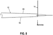
- FIG. 8 illustrates two blade plan views that demonstrate pictorially a potential blade design benefit afforded by the edgewise stabilizer 14.
- a first blade 80 denoted by dashed lines depicts a blade having an edgewise stabilizer pivotably-mounted at the tip end 22 of the blade 12 a short distance inwards from the very tip of the blade, as has been discussed in the previous embodiments.
- This is to be compared with the second blade 82 denoted with full lines 80 which shows an alternate blade profile having comparable performance to the first blade 80.
- the edgewise stabilizer 14 of the second blade 82 is mounted at the very tip of the blade 82, which is flat instead of defining a point as in the first blade 80. Since tip losses are reduced by the effect of the edgewise stabilizer 14 acting as a winglet, this provides the potential to design the blade as having a shorter length and increased chord without sacrificing aerodynamic efficiency.
- the edgewise stabilizer may be conductive so as to act as a lightning receptor for the blade and that a down conductor cable 44 would provide a route to direct current from the edgewise stabilizer 14 to a suitable lightning protection system for the blade. Benefits may be achieved by integrating the down conductor function into the control cable for actuating the edgewise stabilizer 14 between its two operating position.
- the fin 23 is pivotably mounted to the tip end of the blade, in some embodiments the fin may be otherwise movable relative to the blade, for example the fin could be configured to slide out of the blade telescopically into its stabilizing position.
- the edgewise stabilizer is operable to move into the first position in dependence on pitch position. For example, during an emergency stop the stabilizer will be moved into the first position as the blades are pitched into their featured position.
- the edgewise stabilizer may also be used as an aerodynamic brake to reduce rotational speeds of the wind turbine during certain conditions, for example during gusting or continued high wind speeds. This could be readily achieved by programming a control system to drive the motor to cause the edgewise stabilizer to employ when high rotational speeds are detected.
Landscapes
- Engineering & Computer Science (AREA)
- Physics & Mathematics (AREA)
- Fluid Mechanics (AREA)
- Life Sciences & Earth Sciences (AREA)
- Sustainable Development (AREA)
- Sustainable Energy (AREA)
- Chemical & Material Sciences (AREA)
- Combustion & Propulsion (AREA)
- Mechanical Engineering (AREA)
- General Engineering & Computer Science (AREA)
- Wind Motors (AREA)
Claims (18)
- Windkraftanlage (10) umfassend:mindestens ein verstellbares Windkraftanlagenblatt (12), das an einer Nabe (15) montiert ist, wobei das Blatt ein Wurzelende (20), ein Spitzenende (22) und eine Längsachse (24), die sich zwischen dem Wurzelende und dem Spitzenende erstreckt, und eine aerodynamische Profilfläche, die durch eine Druckseite (26) und eine Saugseite (28) definiert ist, aufweist; undeine bewegliche Finne (14), die an dem Spitzenende des Blatts (22) montiert ist, wobei die Finne in eine erste Position (32) eingesetzt wird, abhängig von der Anstellwinkelposition des Blatts und wenn die Windkraftanlage in einem Nichtbetriebsmodus ist;dadurch gekennzeichnet, dass in der ersten Position (32) die Finne sich in einer Richtung im Wesentlichen mit der Längsachse des Blatts ausgerichtet erstreckt und in einer Ebene angeordnet ist, die im Wesentlichen senkrecht zu einer hochkantigen Achse des Blatts an dem Spitzenende ist, sodass die Finne als ein aerodynamischer Stabilisator agiert, um die Effekte von hochkantigen Schwingungen an dem Blatt (12) zu verringern.
- Windkraftanlage nach Anspruch 1, wobei die Finne (14) zu einer zweiten Position (34) beweglich ist, in der sie als ein Winglet agiert.
- Windkraftanlage nach Anspruch 2, wobei in der zweiten Position (34) die Finne (14) sich in einer Richtung quer zu der Längsachse des Blatts (12) erstreckt.
- Windkraftanlage nach Anspruch 2 oder 3, wobei die Finne (14) zwischen der ersten Position (32) und der zweiten Position (34) abhängig von der Blattanstellwinkelposition bewegt wird.
- Windkraftanlage nach einem der vorstehenden Ansprüche, wobei die Finne (14) konfiguriert ist durch einen Elektromotor zu der ersten Position (32) bewegt zu werden, dessen Betrieb mit einem Anstellwinkelsystem der Windkraftanlage verbunden ist.
- Windkraftanlage nach einem der Ansprüche 1 bis 4, wobei die Finne (14) konfiguriert ist, durch ein Kabel zu der ersten Position (32) bewegt zu werden, das von einer Komponente betrieben werden kann, die mit einem Anstellwinkelsystem der Windkraftanlage verknüpft ist.
- Windkraftanlage nach einem der vorstehenden Ansprüche, wobei die Finne (14) zu der ersten Position bewegt wird, wenn die Anstellwinkelposition des Blatts (12) größer als etwa 40° ist.
- Windkraftanlage nach einem der vorstehenden Ansprüche, wobei die Finne (14) konfiguriert ist, in Bezug auf das Blatt (12) frei zu schwenken, wenn die Finne nicht zu der ersten Position (32) bewegt wird.
- Windkraftanlage nach einem der vorstehenden Ansprüche, wobei die Finne (14) konfiguriert ist, in Bezug auf das Blatt (12) frei zu schwenken, wenn die Blattanstellwinkelposition weniger als etwa 40° ist.
- Windkraftanlage nach einem der vorstehenden Ansprüche, wobei die Finne (14) mindestens zum Teil aus einem leitfähigen Material hergestellt ist.
- Windkraftanlage nach Anspruch 10, wobei die Finne (14) elektrisch an ein Blitzschutzsystem des Blatts gekoppelt ist.
- Windkraftanlage nach einem der vorstehenden Ansprüche, wobei die Finne (14) ein Turbulenzverringerungsmerkmal beinhaltet.
- Windkraftanlage nach einem der vorstehenden Ansprüche, wobei die Finne (14) sich über einen Teil der Saugseite (28) des Blatts (12) erstreckt.
- Windraftanlage nach einem der vorstehenden Ansprüche, wobei die Finne (14) sich über einen Teil der Druckseite (26) des Blatts (12) erstreckt.
- Windkraftanlage nach einem der vorstehenden Ansprüche, wobei die Finne (14) sich zum Teil über sowohl die Druck- (26) als auch Saugseite (28) des Blatts (12) erstreckt.
- Windkraftanlage nach einem der Ansprüche 13 bis 15, wobei ein Spalt zwischen der Finne (14) und dem Blatt (12) definiert ist, wo die Finne sich über die Blattoberfläche erstreckt und wo die Finne eine flexible Schürze (50) beinhaltet, die mindestens Teil des Spalts füllt.
- Windkraftanlage nach einem der vorstehenden Ansprüche, wobei die Finne (14) eine Länge von 2% bis 8% einer Länge des Blatts (12) aufweist.
- Windkraftanlage nach einem der vorstehenden Ansprüche, wobei die Finne (14) eine Breite von 0,5% bis 3% einer Länge das Blatts (12) aufweist.
Applications Claiming Priority (1)
| Application Number | Priority Date | Filing Date | Title |
|---|---|---|---|
| DKPA201670690 | 2016-09-08 |
Publications (2)
| Publication Number | Publication Date |
|---|---|
| EP3293392A1 EP3293392A1 (de) | 2018-03-14 |
| EP3293392B1 true EP3293392B1 (de) | 2020-08-12 |
Family
ID=59811244
Family Applications (1)
| Application Number | Title | Priority Date | Filing Date |
|---|---|---|---|
| EP17189947.9A Active EP3293392B1 (de) | 2016-09-08 | 2017-09-07 | Windturbinenschaufel mit einem kantenstabilisator |
Country Status (2)
| Country | Link |
|---|---|
| EP (1) | EP3293392B1 (de) |
| DK (1) | DK3293392T3 (de) |
Families Citing this family (2)
| Publication number | Priority date | Publication date | Assignee | Title |
|---|---|---|---|---|
| CN109737017A (zh) * | 2019-02-21 | 2019-05-10 | 江苏力沛电力工程技术服务有限公司 | 一种风力发电机叶片叶尖防雷装置 |
| US12085061B2 (en) * | 2019-12-30 | 2024-09-10 | Vestas Wind Systems A/S | Method for stabilising a wind turbine blade |
Family Cites Families (6)
| Publication number | Priority date | Publication date | Assignee | Title |
|---|---|---|---|---|
| US4180372A (en) * | 1977-03-02 | 1979-12-25 | Grumman Corporation | Wind rotor automatic air brake |
| JPH05180146A (ja) * | 1991-12-27 | 1993-07-20 | Mitsubishi Heavy Ind Ltd | 風車過負荷防止装置 |
| DK200500899A (da) * | 2005-06-17 | 2006-12-18 | Lm Glasfiber As | Vinge med hængslet vingetip |
| US20100135806A1 (en) * | 2009-06-22 | 2010-06-03 | General Electric Company | Hinged wind turbine blade tips |
| CN202176459U (zh) * | 2011-08-13 | 2012-03-28 | 鲁小和 | 浮力克服重力和弹力悬浮式水平轴风力发电机 |
| CN103016276B (zh) * | 2012-12-07 | 2015-01-21 | 清华大学 | 用于大型风力发电机的两段式倾斜折叠叶片装置 |
-
2017
- 2017-09-07 EP EP17189947.9A patent/EP3293392B1/de active Active
- 2017-09-07 DK DK17189947.9T patent/DK3293392T3/da active
Non-Patent Citations (1)
| Title |
|---|
| None * |
Also Published As
| Publication number | Publication date |
|---|---|
| DK3293392T3 (da) | 2020-08-31 |
| EP3293392A1 (de) | 2018-03-14 |
Similar Documents
| Publication | Publication Date | Title |
|---|---|---|
| US8932024B2 (en) | Wind turbine blade and wind power generator using the same | |
| US7637721B2 (en) | Methods and apparatus for producing wind energy with reduced wind turbine noise | |
| JP5334796B2 (ja) | 風力発電設備のローターブレード | |
| US7927070B2 (en) | Pitch controlled wind turbine blade, a wind turbine and use thereof | |
| EP2341245B1 (de) | Vorrichtung zur Erhöhung des Auftriebs an einem Windturbinenblatt | |
| EP2267298A2 (de) | Windturbineblatt mit drehbaren Finnen an der Spitze | |
| KR101179277B1 (ko) | 나셀 펜스를 갖는 풍력발전기 | |
| US20110110777A1 (en) | Active flow control device and method for affecting a fluid boundary layer of a wind turbine blade | |
| JP5479388B2 (ja) | 風車翼およびこれを備えた風力発電装置 | |
| CA2710524C (en) | Wind turbine blade and assembly | |
| US8851857B2 (en) | Wind turbine blade and wind power generator using the same | |
| EP3026261A1 (de) | Windpark, windenergieerzeugungssystem | |
| US20140271212A1 (en) | Failsafe system for load compensating device | |
| EP3293392B1 (de) | Windturbinenschaufel mit einem kantenstabilisator | |
| KR101216252B1 (ko) | 풍력발전기 블레이드의 팁 에어포일 | |
| WO2015024895A1 (en) | Wind turbine blade | |
| CN112302891A (zh) | 用于风力涡轮的机舱组件 | |
| JP6025869B2 (ja) | 風車及びその運転方法 | |
| JP4533991B1 (ja) | 小型プロペラ風車 | |
| CN112703314B (zh) | 具有带空气动力学特性的叶片承载结构的风力涡轮机 | |
| EP3567243A1 (de) | Windturbinenblattvorderkantenschutz | |
| JP2012092657A (ja) | 風車翼およびこれを備えた風力発電装置ならびに風車翼の設計方法 |
Legal Events
| Date | Code | Title | Description |
|---|---|---|---|
| PUAI | Public reference made under article 153(3) epc to a published international application that has entered the european phase |
Free format text: ORIGINAL CODE: 0009012 |
|
| STAA | Information on the status of an ep patent application or granted ep patent |
Free format text: STATUS: THE APPLICATION HAS BEEN PUBLISHED |
|
| AK | Designated contracting states |
Kind code of ref document: A1 Designated state(s): AL AT BE BG CH CY CZ DE DK EE ES FI FR GB GR HR HU IE IS IT LI LT LU LV MC MK MT NL NO PL PT RO RS SE SI SK SM TR |
|
| AX | Request for extension of the european patent |
Extension state: BA ME |
|
| STAA | Information on the status of an ep patent application or granted ep patent |
Free format text: STATUS: REQUEST FOR EXAMINATION WAS MADE |
|
| 17P | Request for examination filed |
Effective date: 20180823 |
|
| RBV | Designated contracting states (corrected) |
Designated state(s): AL AT BE BG CH CY CZ DE DK EE ES FI FR GB GR HR HU IE IS IT LI LT LU LV MC MK MT NL NO PL PT RO RS SE SI SK SM TR |
|
| GRAP | Despatch of communication of intention to grant a patent |
Free format text: ORIGINAL CODE: EPIDOSNIGR1 |
|
| STAA | Information on the status of an ep patent application or granted ep patent |
Free format text: STATUS: GRANT OF PATENT IS INTENDED |
|
| RIC1 | Information provided on ipc code assigned before grant |
Ipc: F03D 80/30 20160101ALN20200211BHEP Ipc: F03D 1/06 20060101AFI20200211BHEP |
|
| INTG | Intention to grant announced |
Effective date: 20200309 |
|
| GRAS | Grant fee paid |
Free format text: ORIGINAL CODE: EPIDOSNIGR3 |
|
| GRAA | (expected) grant |
Free format text: ORIGINAL CODE: 0009210 |
|
| STAA | Information on the status of an ep patent application or granted ep patent |
Free format text: STATUS: THE PATENT HAS BEEN GRANTED |
|
| AK | Designated contracting states |
Kind code of ref document: B1 Designated state(s): AL AT BE BG CH CY CZ DE DK EE ES FI FR GB GR HR HU IE IS IT LI LT LU LV MC MK MT NL NO PL PT RO RS SE SI SK SM TR |
|
| REG | Reference to a national code |
Ref country code: CH Ref legal event code: EP |
|
| REG | Reference to a national code |
Ref country code: DK Ref legal event code: T3 Effective date: 20200827 |
|
| REG | Reference to a national code |
Ref country code: IE Ref legal event code: FG4D |
|
| REG | Reference to a national code |
Ref country code: DE Ref legal event code: R096 Ref document number: 602017021448 Country of ref document: DE |
|
| REG | Reference to a national code |
Ref country code: AT Ref legal event code: REF Ref document number: 1301785 Country of ref document: AT Kind code of ref document: T Effective date: 20200915 |
|
| REG | Reference to a national code |
Ref country code: LT Ref legal event code: MG4D |
|
| REG | Reference to a national code |
Ref country code: NL Ref legal event code: MP Effective date: 20200812 |
|
| PG25 | Lapsed in a contracting state [announced via postgrant information from national office to epo] |
Ref country code: GR Free format text: LAPSE BECAUSE OF FAILURE TO SUBMIT A TRANSLATION OF THE DESCRIPTION OR TO PAY THE FEE WITHIN THE PRESCRIBED TIME-LIMIT Effective date: 20201113 Ref country code: NO Free format text: LAPSE BECAUSE OF FAILURE TO SUBMIT A TRANSLATION OF THE DESCRIPTION OR TO PAY THE FEE WITHIN THE PRESCRIBED TIME-LIMIT Effective date: 20201112 Ref country code: LT Free format text: LAPSE BECAUSE OF FAILURE TO SUBMIT A TRANSLATION OF THE DESCRIPTION OR TO PAY THE FEE WITHIN THE PRESCRIBED TIME-LIMIT Effective date: 20200812 Ref country code: BG Free format text: LAPSE BECAUSE OF FAILURE TO SUBMIT A TRANSLATION OF THE DESCRIPTION OR TO PAY THE FEE WITHIN THE PRESCRIBED TIME-LIMIT Effective date: 20201112 Ref country code: FI Free format text: LAPSE BECAUSE OF FAILURE TO SUBMIT A TRANSLATION OF THE DESCRIPTION OR TO PAY THE FEE WITHIN THE PRESCRIBED TIME-LIMIT Effective date: 20200812 Ref country code: HR Free format text: LAPSE BECAUSE OF FAILURE TO SUBMIT A TRANSLATION OF THE DESCRIPTION OR TO PAY THE FEE WITHIN THE PRESCRIBED TIME-LIMIT Effective date: 20200812 Ref country code: SE Free format text: LAPSE BECAUSE OF FAILURE TO SUBMIT A TRANSLATION OF THE DESCRIPTION OR TO PAY THE FEE WITHIN THE PRESCRIBED TIME-LIMIT Effective date: 20200812 |
|
| REG | Reference to a national code |
Ref country code: AT Ref legal event code: MK05 Ref document number: 1301785 Country of ref document: AT Kind code of ref document: T Effective date: 20200812 |
|
| PG25 | Lapsed in a contracting state [announced via postgrant information from national office to epo] |
Ref country code: LV Free format text: LAPSE BECAUSE OF FAILURE TO SUBMIT A TRANSLATION OF THE DESCRIPTION OR TO PAY THE FEE WITHIN THE PRESCRIBED TIME-LIMIT Effective date: 20200812 Ref country code: RS Free format text: LAPSE BECAUSE OF FAILURE TO SUBMIT A TRANSLATION OF THE DESCRIPTION OR TO PAY THE FEE WITHIN THE PRESCRIBED TIME-LIMIT Effective date: 20200812 Ref country code: PL Free format text: LAPSE BECAUSE OF FAILURE TO SUBMIT A TRANSLATION OF THE DESCRIPTION OR TO PAY THE FEE WITHIN THE PRESCRIBED TIME-LIMIT Effective date: 20200812 Ref country code: NL Free format text: LAPSE BECAUSE OF FAILURE TO SUBMIT A TRANSLATION OF THE DESCRIPTION OR TO PAY THE FEE WITHIN THE PRESCRIBED TIME-LIMIT Effective date: 20200812 Ref country code: IS Free format text: LAPSE BECAUSE OF FAILURE TO SUBMIT A TRANSLATION OF THE DESCRIPTION OR TO PAY THE FEE WITHIN THE PRESCRIBED TIME-LIMIT Effective date: 20201212 |
|
| PG25 | Lapsed in a contracting state [announced via postgrant information from national office to epo] |
Ref country code: SM Free format text: LAPSE BECAUSE OF FAILURE TO SUBMIT A TRANSLATION OF THE DESCRIPTION OR TO PAY THE FEE WITHIN THE PRESCRIBED TIME-LIMIT Effective date: 20200812 Ref country code: EE Free format text: LAPSE BECAUSE OF FAILURE TO SUBMIT A TRANSLATION OF THE DESCRIPTION OR TO PAY THE FEE WITHIN THE PRESCRIBED TIME-LIMIT Effective date: 20200812 Ref country code: CZ Free format text: LAPSE BECAUSE OF FAILURE TO SUBMIT A TRANSLATION OF THE DESCRIPTION OR TO PAY THE FEE WITHIN THE PRESCRIBED TIME-LIMIT Effective date: 20200812 Ref country code: RO Free format text: LAPSE BECAUSE OF FAILURE TO SUBMIT A TRANSLATION OF THE DESCRIPTION OR TO PAY THE FEE WITHIN THE PRESCRIBED TIME-LIMIT Effective date: 20200812 |
|
| REG | Reference to a national code |
Ref country code: CH Ref legal event code: PL |
|
| REG | Reference to a national code |
Ref country code: DE Ref legal event code: R097 Ref document number: 602017021448 Country of ref document: DE |
|
| PG25 | Lapsed in a contracting state [announced via postgrant information from national office to epo] |
Ref country code: MC Free format text: LAPSE BECAUSE OF FAILURE TO SUBMIT A TRANSLATION OF THE DESCRIPTION OR TO PAY THE FEE WITHIN THE PRESCRIBED TIME-LIMIT Effective date: 20200812 Ref country code: AT Free format text: LAPSE BECAUSE OF FAILURE TO SUBMIT A TRANSLATION OF THE DESCRIPTION OR TO PAY THE FEE WITHIN THE PRESCRIBED TIME-LIMIT Effective date: 20200812 Ref country code: AL Free format text: LAPSE BECAUSE OF FAILURE TO SUBMIT A TRANSLATION OF THE DESCRIPTION OR TO PAY THE FEE WITHIN THE PRESCRIBED TIME-LIMIT Effective date: 20200812 Ref country code: ES Free format text: LAPSE BECAUSE OF FAILURE TO SUBMIT A TRANSLATION OF THE DESCRIPTION OR TO PAY THE FEE WITHIN THE PRESCRIBED TIME-LIMIT Effective date: 20200812 |
|
| PLBE | No opposition filed within time limit |
Free format text: ORIGINAL CODE: 0009261 |
|
| REG | Reference to a national code |
Ref country code: BE Ref legal event code: MM Effective date: 20200930 |
|
| STAA | Information on the status of an ep patent application or granted ep patent |
Free format text: STATUS: NO OPPOSITION FILED WITHIN TIME LIMIT |
|
| PG25 | Lapsed in a contracting state [announced via postgrant information from national office to epo] |
Ref country code: SK Free format text: LAPSE BECAUSE OF FAILURE TO SUBMIT A TRANSLATION OF THE DESCRIPTION OR TO PAY THE FEE WITHIN THE PRESCRIBED TIME-LIMIT Effective date: 20200812 Ref country code: LU Free format text: LAPSE BECAUSE OF NON-PAYMENT OF DUE FEES Effective date: 20200907 |
|
| 26N | No opposition filed |
Effective date: 20210514 |
|
| PG25 | Lapsed in a contracting state [announced via postgrant information from national office to epo] |
Ref country code: IT Free format text: LAPSE BECAUSE OF FAILURE TO SUBMIT A TRANSLATION OF THE DESCRIPTION OR TO PAY THE FEE WITHIN THE PRESCRIBED TIME-LIMIT Effective date: 20200812 Ref country code: FR Free format text: LAPSE BECAUSE OF NON-PAYMENT OF DUE FEES Effective date: 20201012 |
|
| PG25 | Lapsed in a contracting state [announced via postgrant information from national office to epo] |
Ref country code: LI Free format text: LAPSE BECAUSE OF NON-PAYMENT OF DUE FEES Effective date: 20200930 Ref country code: IE Free format text: LAPSE BECAUSE OF NON-PAYMENT OF DUE FEES Effective date: 20200907 Ref country code: SI Free format text: LAPSE BECAUSE OF FAILURE TO SUBMIT A TRANSLATION OF THE DESCRIPTION OR TO PAY THE FEE WITHIN THE PRESCRIBED TIME-LIMIT Effective date: 20200812 Ref country code: BE Free format text: LAPSE BECAUSE OF NON-PAYMENT OF DUE FEES Effective date: 20200930 Ref country code: CH Free format text: LAPSE BECAUSE OF NON-PAYMENT OF DUE FEES Effective date: 20200930 |
|
| PG25 | Lapsed in a contracting state [announced via postgrant information from national office to epo] |
Ref country code: TR Free format text: LAPSE BECAUSE OF FAILURE TO SUBMIT A TRANSLATION OF THE DESCRIPTION OR TO PAY THE FEE WITHIN THE PRESCRIBED TIME-LIMIT Effective date: 20200812 Ref country code: MT Free format text: LAPSE BECAUSE OF FAILURE TO SUBMIT A TRANSLATION OF THE DESCRIPTION OR TO PAY THE FEE WITHIN THE PRESCRIBED TIME-LIMIT Effective date: 20200812 Ref country code: CY Free format text: LAPSE BECAUSE OF FAILURE TO SUBMIT A TRANSLATION OF THE DESCRIPTION OR TO PAY THE FEE WITHIN THE PRESCRIBED TIME-LIMIT Effective date: 20200812 |
|
| PG25 | Lapsed in a contracting state [announced via postgrant information from national office to epo] |
Ref country code: MK Free format text: LAPSE BECAUSE OF FAILURE TO SUBMIT A TRANSLATION OF THE DESCRIPTION OR TO PAY THE FEE WITHIN THE PRESCRIBED TIME-LIMIT Effective date: 20200812 |
|
| PG25 | Lapsed in a contracting state [announced via postgrant information from national office to epo] |
Ref country code: PT Free format text: LAPSE BECAUSE OF FAILURE TO SUBMIT A TRANSLATION OF THE DESCRIPTION OR TO PAY THE FEE WITHIN THE PRESCRIBED TIME-LIMIT Effective date: 20200812 |
|
| P01 | Opt-out of the competence of the unified patent court (upc) registered |
Effective date: 20230521 |
|
| PGFP | Annual fee paid to national office [announced via postgrant information from national office to epo] |
Ref country code: GB Payment date: 20230926 Year of fee payment: 7 |
|
| PGFP | Annual fee paid to national office [announced via postgrant information from national office to epo] |
Ref country code: DK Payment date: 20230927 Year of fee payment: 7 Ref country code: DE Payment date: 20230928 Year of fee payment: 7 |