EP3293103A1 - A transmission and an electric vehicle provided with the transmission - Google Patents
A transmission and an electric vehicle provided with the transmission Download PDFInfo
- Publication number
- EP3293103A1 EP3293103A1 EP17186439.0A EP17186439A EP3293103A1 EP 3293103 A1 EP3293103 A1 EP 3293103A1 EP 17186439 A EP17186439 A EP 17186439A EP 3293103 A1 EP3293103 A1 EP 3293103A1
- Authority
- EP
- European Patent Office
- Prior art keywords
- transmission
- transmission mechanism
- gear
- wheel
- unidirectional
- Prior art date
- Legal status (The legal status is an assumption and is not a legal conclusion. Google has not performed a legal analysis and makes no representation as to the accuracy of the status listed.)
- Granted
Links
Images

Classifications
-
- B—PERFORMING OPERATIONS; TRANSPORTING
- B60—VEHICLES IN GENERAL
- B60K—ARRANGEMENT OR MOUNTING OF PROPULSION UNITS OR OF TRANSMISSIONS IN VEHICLES; ARRANGEMENT OR MOUNTING OF PLURAL DIVERSE PRIME-MOVERS IN VEHICLES; AUXILIARY DRIVES FOR VEHICLES; INSTRUMENTATION OR DASHBOARDS FOR VEHICLES; ARRANGEMENTS IN CONNECTION WITH COOLING, AIR INTAKE, GAS EXHAUST OR FUEL SUPPLY OF PROPULSION UNITS IN VEHICLES
- B60K17/00—Arrangement or mounting of transmissions in vehicles
- B60K17/04—Arrangement or mounting of transmissions in vehicles characterised by arrangement, location or kind of gearing
- B60K17/043—Transmission unit disposed in on near the vehicle wheel, or between the differential gear unit and the wheel
-
- B—PERFORMING OPERATIONS; TRANSPORTING
- B62—LAND VEHICLES FOR TRAVELLING OTHERWISE THAN ON RAILS
- B62M—RIDER PROPULSION OF WHEELED VEHICLES OR SLEDGES; POWERED PROPULSION OF SLEDGES OR SINGLE-TRACK CYCLES; TRANSMISSIONS SPECIALLY ADAPTED FOR SUCH VEHICLES
- B62M9/00—Transmissions characterised by use of an endless chain, belt, or the like
- B62M9/02—Transmissions characterised by use of an endless chain, belt, or the like of unchangeable ratio
-
- B—PERFORMING OPERATIONS; TRANSPORTING
- B60—VEHICLES IN GENERAL
- B60K—ARRANGEMENT OR MOUNTING OF PROPULSION UNITS OR OF TRANSMISSIONS IN VEHICLES; ARRANGEMENT OR MOUNTING OF PLURAL DIVERSE PRIME-MOVERS IN VEHICLES; AUXILIARY DRIVES FOR VEHICLES; INSTRUMENTATION OR DASHBOARDS FOR VEHICLES; ARRANGEMENTS IN CONNECTION WITH COOLING, AIR INTAKE, GAS EXHAUST OR FUEL SUPPLY OF PROPULSION UNITS IN VEHICLES
- B60K17/00—Arrangement or mounting of transmissions in vehicles
- B60K17/04—Arrangement or mounting of transmissions in vehicles characterised by arrangement, location or kind of gearing
- B60K17/14—Arrangement or mounting of transmissions in vehicles characterised by arrangement, location or kind of gearing the motor of fluid or electric gearing being disposed in, or adjacent to, traction wheel
-
- B—PERFORMING OPERATIONS; TRANSPORTING
- B60—VEHICLES IN GENERAL
- B60K—ARRANGEMENT OR MOUNTING OF PROPULSION UNITS OR OF TRANSMISSIONS IN VEHICLES; ARRANGEMENT OR MOUNTING OF PLURAL DIVERSE PRIME-MOVERS IN VEHICLES; AUXILIARY DRIVES FOR VEHICLES; INSTRUMENTATION OR DASHBOARDS FOR VEHICLES; ARRANGEMENTS IN CONNECTION WITH COOLING, AIR INTAKE, GAS EXHAUST OR FUEL SUPPLY OF PROPULSION UNITS IN VEHICLES
- B60K7/00—Disposition of motor in, or adjacent to, traction wheel
- B60K7/0007—Disposition of motor in, or adjacent to, traction wheel the motor being electric
-
- B—PERFORMING OPERATIONS; TRANSPORTING
- B62—LAND VEHICLES FOR TRAVELLING OTHERWISE THAN ON RAILS
- B62M—RIDER PROPULSION OF WHEELED VEHICLES OR SLEDGES; POWERED PROPULSION OF SLEDGES OR SINGLE-TRACK CYCLES; TRANSMISSIONS SPECIALLY ADAPTED FOR SUCH VEHICLES
- B62M11/00—Transmissions characterised by the use of interengaging toothed wheels or frictionally-engaging wheels
- B62M11/02—Transmissions characterised by the use of interengaging toothed wheels or frictionally-engaging wheels of unchangeable ratio
-
- F—MECHANICAL ENGINEERING; LIGHTING; HEATING; WEAPONS; BLASTING
- F16—ENGINEERING ELEMENTS AND UNITS; GENERAL MEASURES FOR PRODUCING AND MAINTAINING EFFECTIVE FUNCTIONING OF MACHINES OR INSTALLATIONS; THERMAL INSULATION IN GENERAL
- F16H—GEARING
- F16H7/00—Gearings for conveying rotary motion by endless flexible members
- F16H7/02—Gearings for conveying rotary motion by endless flexible members with belts; with V-belts
- F16H7/023—Gearings for conveying rotary motion by endless flexible members with belts; with V-belts with belts having a toothed contact surface or regularly spaced bosses or hollows for slipless or nearly slipless meshing with complementary profiled contact surface of a pulley
-
- F—MECHANICAL ENGINEERING; LIGHTING; HEATING; WEAPONS; BLASTING
- F16—ENGINEERING ELEMENTS AND UNITS; GENERAL MEASURES FOR PRODUCING AND MAINTAINING EFFECTIVE FUNCTIONING OF MACHINES OR INSTALLATIONS; THERMAL INSULATION IN GENERAL
- F16H—GEARING
- F16H7/00—Gearings for conveying rotary motion by endless flexible members
- F16H7/08—Means for varying tension of belts, ropes or chains
- F16H7/0848—Means for varying tension of belts, ropes or chains with means for impeding reverse motion
-
- B—PERFORMING OPERATIONS; TRANSPORTING
- B60—VEHICLES IN GENERAL
- B60K—ARRANGEMENT OR MOUNTING OF PROPULSION UNITS OR OF TRANSMISSIONS IN VEHICLES; ARRANGEMENT OR MOUNTING OF PLURAL DIVERSE PRIME-MOVERS IN VEHICLES; AUXILIARY DRIVES FOR VEHICLES; INSTRUMENTATION OR DASHBOARDS FOR VEHICLES; ARRANGEMENTS IN CONNECTION WITH COOLING, AIR INTAKE, GAS EXHAUST OR FUEL SUPPLY OF PROPULSION UNITS IN VEHICLES
- B60K7/00—Disposition of motor in, or adjacent to, traction wheel
- B60K2007/0061—Disposition of motor in, or adjacent to, traction wheel the motor axle being parallel to the wheel axle
-
- B—PERFORMING OPERATIONS; TRANSPORTING
- B60—VEHICLES IN GENERAL
- B60Y—INDEXING SCHEME RELATING TO ASPECTS CROSS-CUTTING VEHICLE TECHNOLOGY
- B60Y2200/00—Type of vehicle
- B60Y2200/90—Vehicles comprising electric prime movers
- B60Y2200/91—Electric vehicles
-
- B—PERFORMING OPERATIONS; TRANSPORTING
- B62—LAND VEHICLES FOR TRAVELLING OTHERWISE THAN ON RAILS
- B62K—CYCLES; CYCLE FRAMES; CYCLE STEERING DEVICES; RIDER-OPERATED TERMINAL CONTROLS SPECIALLY ADAPTED FOR CYCLES; CYCLE AXLE SUSPENSIONS; CYCLE SIDECARS, FORECARS, OR THE LIKE
- B62K2202/00—Motorised scooters
-
- B—PERFORMING OPERATIONS; TRANSPORTING
- B62—LAND VEHICLES FOR TRAVELLING OTHERWISE THAN ON RAILS
- B62K—CYCLES; CYCLE FRAMES; CYCLE STEERING DEVICES; RIDER-OPERATED TERMINAL CONTROLS SPECIALLY ADAPTED FOR CYCLES; CYCLE AXLE SUSPENSIONS; CYCLE SIDECARS, FORECARS, OR THE LIKE
- B62K2204/00—Adaptations for driving cycles by electric motor
Definitions
- the present invention relates to the technical field of mechanical apparatus, particularly to a transmission and an electric vehicle provided with the transmission, specifically to a transmission with small size, light weight, being capable of efficiently improving endurance mileage, and low energy consumption, and to an electric vehicle provided with the transmission.
- the objectives of the present invention are to provide a transmission with small size, light weight, being capable of efficiently improving endurance mileage, and low energy consumption, and to provide an electric vehicle provided with the transmission, so as to solve the problem of large coasting resistance and short coasting distance due to the conventional drive train being not provided with a unidirectional transmission mechanism when a vehicle is coasting.
- the present invention provides a transmission with an input end connected with a driving device, an output end connected with a rear wheel, the transmission comprising a gear transmission mechanism and a pulley transmission mechanism, the gear transmission mechanism comprising a primary gear connected to the driving mechanism; the pulley transmission mechanism comprising a driving wheel, a driven wheel and a synchronous belt; the driving wheel being connected with the primary gear through a gear shaft, a unidirectional transmission mechanism connected to the driven wheel being provided in the rear wheel, the unidirectional transmission mechanism being used for driving the rear wheel to rotate.
- the unidirectional transmission mechanism is connected with the driven wheel through a thread bushing.
- the rear wheel is provided with a first gear
- the periphery of the unidirectional transmission mechanism is provided with a second gear engaged with the first gear
- the unidirectional transmission mechanism is a unidirectional flywheel or unidirectional bearing.
- the rear wheel is further provided with a wheel cover plate at the side away from the driven wheel, and the wheel cover plate is fixed to the rear wheel through screws.
- the transmission further comprises a box body provided with an opening, one side of the opening being provided with a box body cover, the other side of the opening being provided with a cover plate, the box body cover, cover plate and box body constituting a closed housing, both of the gear transmission mechanism and the pulley transmission mechanism being provided in the housing.
- a sealing plate is provided at the connection of the box body cover and the box body, and the sealing plate is disposed over the gear shaft.
- the driving device is a motor
- an output shaft of the motor is connected with the primary gear
- the output shaft is used for driving the primary gear to rotate.
- the present invention also provides an electric vehicle comprising the transmission above.
- the present invention provides a transmission with an input end connected with a driving device, an output end connected with a rear wheel, the transmission comprising a gear transmission mechanism and a pulley transmission mechanism, the gear transmission mechanism comprising a primary gear connected to the driving mechanism; the pulley transmission mechanism comprising a driving wheel, a driven wheel and a synchronous belt; the driving wheel being connected with the primary gear through a gear shaft, the rear wheel provided with a unidirectional transmission mechanism connected to the driven wheel, the unidirectional transmission mechanism being used for driving the rear wheel to rotate.
- the transmission provided by the present application is with simple structure, occupies small space, and is light in weight; it provides power output by the driving device, transmits power to the pulley transmission mechanism by the gear transmission mechanism, and the pulley transmission mechanism drives the rear wheel to rotate through the unidirectional transmission mechanism, such that the vehicle moves forward; when the power output is stopped, due to the inertia effect of the vehicle and the small rotation resistance of the unidirectional transmission mechanism, the vehicle can smoothly coast, while the driving mechanism, gear transmission mechanism and pulley transmission mechanism are not rotating, thereby achieving the advantageous effects of saving power consumption and improving endurance mileage.
- the transmission is of strong practicability, beneficial to the standardized production and promotion.
- 1 box body; 2: synchronous belt; 3: driven wheel; 4: thread bushing; 5: cover plate; 6: rear wheel; 7: unidirectional transmission mechanism; 8: wheel cover plate; 9: motor; 10: box body cover; 11: primary gear; 12: sealing plate; 13: gear shaft; 14: driving wheel.
- the embodiment of the present invention provides a transmission, an input end of the transmission being connected with a driving device, the driving device providing a power source for the transmission, an output end being connected with a rear wheel 6 for driving the rear wheel 6 to rotate, such that the vehicle moves forward;
- the transmission specifically comprising a gear transmission mechanism and a pulley transmission mechanism, the gear transmission mechanism comprising a primary gear 11 connected to the driving mechanism, the driving mechanism driving the primary gear 11 to rotate;
- the pulley transmission mechanism comprising a driving wheel 14, a driven wheel 3 and a synchronous belt 2;
- the driving wheel 14 being connected with the primary gear 11 through a gear shaft 13, a unidirectional transmission mechanism 7 connected to the driven wheel 3 being provided in the rear wheel 6, the unidirectional transmission mechanism 7 being used for driving the rear wheel 6 to rotate.
- the transmission provided by the present application comprises a two-stage gearshift, wherein the power provided by the driving device is transmitted to the pulley transmission mechanism through the gear transmission mechanism, the pulley transmission mechanism transmits the power to the unidirectional transmission mechanism 7, the unidirectional transmission mechanism 7 further drives the rear wheel 6 to rotate.
- the transmission is with simple structure, occupies small space, and is light in weight. It efficiently solves the problem of complex and cumbersome internal structure of the existing transmission.
- the driving wheel 14 is a secondary front pulley of the synchronous belt 2
- the driven wheel 3 is a secondary rear pulley of the synchronous belt 2.
- the transmission provided by the present application provides power output by the driving device, transmits the power to the pulley transmission mechanism by the gear transmission mechanism, and the pulley transmission mechanism drives the rear wheel 6 to rotate through the unidirectional transmission mechanism 7, such that the vehicle moves forward; when the power output is stopped, due to the inertia effect of the vehicle and the relatively small rotation resistance of the unidirectional transmission mechanism 7, the vehicle can smoothly coast, while the driving mechanism, gear transmission mechanism and pulley transmission mechanism are not rotating, thereby achieving the advantageous effects of saving power consumption and improving endurance mileage.
- the unidirectional transmission mechanism 7 is connected with the driven wheel 3 by a thread bushing 4.
- the inner sides of the unidirectional transmission mechanism 7 and the driven wheel 3 are both provided with inner threads matching the thread bushing 4.
- This coupling method is of good transmission effect, and is simple in process, being capable of improving the installation efficiency of the transmission and is also easy for maintenance and overhaul.
- a first gear is provided in the rear wheel 6, and the periphery of the unidirectional transmission mechanism 7 is provided with a second gear engaged with the first gear, so as to complete the power transmission from the unidirectional transmission mechanism 7 to the rear wheel 6.
- gear engaging which is conducive to ensuring the normal operation of the transmission.
- it is of light weight and small size, is simple in manufacturing process and low in production costs. It is helpful for improving economy, suitable for electric scooters with small costs.
- the unidirectional transmission mechanism 7 is a unidirectional flywheel or unidirectional bearing.
- a ratchet is provided in the unidirectional flywheel, through the ratchet a unidirectional rotation transmission is achieved;
- the unidirectional bearing is a bearing that can freely rotate in one direction and locked in the other direction. It is of small resistance by providing the unidirectional flywheel or the unidirectional bearing, so that the vehicle can smoothly coast; particularly for a small electric scooter, it can be ridden or driven in the form of one foot thrusting against the ground as a non-powered scooter, when the vehicle battery runs out of power.
- the rear wheel 6 is further provided with a wheel cover plate 8 at the side away from the driven wheel 3, and the wheel cover plate 8 is fixed to the rear wheel 6 through screws.
- the wheel cover plate 8 and the rear wheel 6 can also use other fixing connection methods such as engaging, embedding or clamping.
- the transmission further comprises a box body 1 provided with an opening, one side of the opening being provided with a box body cover 10, the other side of the opening being provided with a cover plate 5, the box body cover 10, cover plate 5 and box body 1 constituting a closed housing, both of the gear transmission mechanism and the pulley transmission mechanism being provided in the housing.
- the cover plate 5 is provided at the connection of the rear wheel 6 and the box body 1.
- a sealing plate 12 is provided at the connection of the box body cover 10 and the box body 1, and the sealing plate 12 is disposed over the gear shaft 13.
- the contour shape of the sealing plate 12 matches the contour shape of the opening of the box body 1. It avoids the overflow of the lubricating oil on the primary gear 11, which affects the normal use of the transmission, by providing the sealing plate 12.
- the driving device is a motor 9, an output shaft of the motor 9 is connected with the primary gear 11.
- the output shaft is used for driving the primary gear 11 to rotate.
- the motor 9 is a 12V high-rotation-speed micro-motor 9. Different from the conventional 6812-type motor 9, it is of lighter weight, lower cost and better economy.
- the driving device can also be other power sources such as battery, solar or hydraulic or other power sources.
- the present invention also provides an electric vehicle comprising the transmission above. It consumes low power, is capable of efficiently improving the endurance mileage of the electric vehicle, significantly enhancing the demands for transportation of the consumers, by using the transmission with the structure above. It should be noted that due to the light weight and small size, the transmission provided by the present application can also be widely used in the field of electric scooter, it is particularly suitable for electric scooters with two wheels, three wheels and four wheels. In addition to the descriptions above, the transmission above can also be suitable for ordinary vehicles, achieving the advantageous effect of reducing power consumption.
- the present invention provides a transmission, with an input end connected with a driving device, an output end connected with a rear wheel, comprising a gear transmission mechanism and a pulley transmission mechanism, the gear transmission mechanism comprising a primary gear connected to the driving mechanism; the pulley transmission mechanism comprising a driving wheel, a driven wheel and a synchronous belt; the driving wheel being connected with the primary gear through a gear shaft, a unidirectional transmission mechanism connected to the driven wheel being provided in the rear wheel, the unidirectional transmission mechanism being used for driving the rear wheel to rotate.
- the transmission provided by the present application is with simple structure, small footprint and light weight; and provides power output by the driving device, transmits power to the pulley transmission mechanism by the gear transmission mechanism.
- the pulley transmission mechanism drives the rear wheel to rotate through the unidirectional transmission mechanism, such that the vehicle moves forward; when the power output is stopped, due to the inertia effect of the vehicle and the small rotation resistance of the unidirectional transmission mechanism, the vehicle can smoothly coast while the driving mechanism, gear transmission mechanism and pulley transmission mechanism are not rotating, thereby achieving the advantageous effects of saving power consumption and improving endurance mileage.
- the transmission is of strong practicability, is beneficial to the standardized production and promotion.
Landscapes
- Engineering & Computer Science (AREA)
- Mechanical Engineering (AREA)
- General Engineering & Computer Science (AREA)
- Chemical & Material Sciences (AREA)
- Combustion & Propulsion (AREA)
- Transportation (AREA)
- Transmissions By Endless Flexible Members (AREA)
- Structure Of Transmissions (AREA)
- Transmission Devices (AREA)
Abstract
Description
- The present invention relates to the technical field of mechanical apparatus, particularly to a transmission and an electric vehicle provided with the transmission, specifically to a transmission with small size, light weight, being capable of efficiently improving endurance mileage, and low energy consumption, and to an electric vehicle provided with the transmission.
- At present, most of transmissions applied to automobiles are relatively complex and cumbersome. When applied to an electric vehicle, particularly for an electric scooter, the transmission is required to be small, simple, practical, and to be with high safety factor and long endurance mileage. However, when a vehicle is coasting, since the existing drive train is not provided with a unidirectional transmission, both of the drive train and power unit will rotate during the coasting, thereby resulting in large coasting resistance and short coasting distance. The existing drive train is poor in practicality, unable to satisfy the requirements for a transmission by various transportation tools in the market.
- The objectives of the present invention are to provide a transmission with small size, light weight, being capable of efficiently improving endurance mileage, and low energy consumption, and to provide an electric vehicle provided with the transmission, so as to solve the problem of large coasting resistance and short coasting distance due to the conventional drive train being not provided with a unidirectional transmission mechanism when a vehicle is coasting.
- In order to solve the technical problem above, the present invention provides a transmission with an input end connected with a driving device, an output end connected with a rear wheel, the transmission comprising a gear transmission mechanism and a pulley transmission mechanism, the gear transmission mechanism comprising a primary gear connected to the driving mechanism; the pulley transmission mechanism comprising a driving wheel, a driven wheel and a synchronous belt; the driving wheel being connected with the primary gear through a gear shaft, a unidirectional transmission mechanism connected to the driven wheel being provided in the rear wheel, the unidirectional transmission mechanism being used for driving the rear wheel to rotate.
- Wherein, the unidirectional transmission mechanism is connected with the driven wheel through a thread bushing.
- Wherein, the rear wheel is provided with a first gear, and the periphery of the unidirectional transmission mechanism is provided with a second gear engaged with the first gear.
- Wherein, the unidirectional transmission mechanism is a unidirectional flywheel or unidirectional bearing.
- Wherein, the rear wheel is further provided with a wheel cover plate at the side away from the driven wheel, and the wheel cover plate is fixed to the rear wheel through screws.
- Wherein, the transmission further comprises a box body provided with an opening, one side of the opening being provided with a box body cover, the other side of the opening being provided with a cover plate, the box body cover, cover plate and box body constituting a closed housing, both of the gear transmission mechanism and the pulley transmission mechanism being provided in the housing.
- Wherein, a sealing plate is provided at the connection of the box body cover and the box body, and the sealing plate is disposed over the gear shaft.
- Wherein, the driving device is a motor, an output shaft of the motor is connected with the primary gear, the output shaft is used for driving the primary gear to rotate.
- The present invention also provides an electric vehicle comprising the transmission above.
- The technical solutions above of the present invention have the following advantages: the present invention provides a transmission with an input end connected with a driving device, an output end connected with a rear wheel, the transmission comprising a gear transmission mechanism and a pulley transmission mechanism, the gear transmission mechanism comprising a primary gear connected to the driving mechanism; the pulley transmission mechanism comprising a driving wheel, a driven wheel and a synchronous belt; the driving wheel being connected with the primary gear through a gear shaft, the rear wheel provided with a unidirectional transmission mechanism connected to the driven wheel, the unidirectional transmission mechanism being used for driving the rear wheel to rotate. The transmission provided by the present application is with simple structure, occupies small space, and is light in weight; it provides power output by the driving device, transmits power to the pulley transmission mechanism by the gear transmission mechanism, and the pulley transmission mechanism drives the rear wheel to rotate through the unidirectional transmission mechanism, such that the vehicle moves forward; when the power output is stopped, due to the inertia effect of the vehicle and the small rotation resistance of the unidirectional transmission mechanism, the vehicle can smoothly coast, while the driving mechanism, gear transmission mechanism and pulley transmission mechanism are not rotating, thereby achieving the advantageous effects of saving power consumption and improving endurance mileage. The transmission is of strong practicability, beneficial to the standardized production and promotion.
-
-
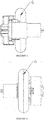
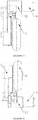
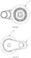
Figure 1 is an assembly structural diagram of a transmission of a transmission embodiment of the present invention; -
Figure 2 is an isometric view at left front 45° of a transmission of a transmission embodiment of the present invention; -
Figure 3 is a front view of a transmission of a transmission embodiment of the present invention; -
Figure 4 is a rear view of a transmission of a transmission embodiment of the present invention; -
Figure 5 is a bottom view of a transmission of a transmission embodiment of the present invention; -
Figure 6 is a top view of a transmission of a transmission embodiment of the present invention; -
Figure 7 is a left view of a transmission of a transmission embodiment of the present invention; -
Figure 8 is a right view of a transmission of a transmission embodiment of the present invention. - In the
figures: 1 : box body; 2: synchronous belt; 3: driven wheel; 4: thread bushing; 5: cover plate; 6: rear wheel; 7: unidirectional transmission mechanism; 8: wheel cover plate; 9: motor; 10: box body cover; 11: primary gear; 12: sealing plate; 13: gear shaft; 14: driving wheel. - In order to make the objectives, technical solutions and advantages of the embodiments of the present invention clearer, a clear and complete description of the technical solutions in the embodiments of the present invention will be made hereinafter in combination with the drawings in the embodiments of the present invention. It is apparent that the described embodiments are not all but a part of the embodiments of the present invention. Based on the embodiments of the present invention, all other embodiments obtained by those of ordinary skills in the art without creative work are within the scope of the present invention.
- As illustrated in
Figures 1 to 8 , the embodiment of the present invention provides a transmission, an input end of the transmission being connected with a driving device, the driving device providing a power source for the transmission, an output end being connected with arear wheel 6 for driving therear wheel 6 to rotate, such that the vehicle moves forward; the transmission specifically comprising a gear transmission mechanism and a pulley transmission mechanism, the gear transmission mechanism comprising aprimary gear 11 connected to the driving mechanism, the driving mechanism driving theprimary gear 11 to rotate; the pulley transmission mechanism comprising adriving wheel 14, a drivenwheel 3 and a synchronous belt 2; thedriving wheel 14 being connected with theprimary gear 11 through a gear shaft 13, a unidirectional transmission mechanism 7 connected to the drivenwheel 3 being provided in therear wheel 6, the unidirectional transmission mechanism 7 being used for driving therear wheel 6 to rotate. In the present embodiment, the transmission provided by the present application comprises a two-stage gearshift, wherein the power provided by the driving device is transmitted to the pulley transmission mechanism through the gear transmission mechanism, the pulley transmission mechanism transmits the power to the unidirectional transmission mechanism 7, the unidirectional transmission mechanism 7 further drives therear wheel 6 to rotate. The transmission is with simple structure, occupies small space, and is light in weight. It efficiently solves the problem of complex and cumbersome internal structure of the existing transmission. Wherein, thedriving wheel 14 is a secondary front pulley of the synchronous belt 2, and the drivenwheel 3 is a secondary rear pulley of the synchronous belt 2. - Specifically, when operating, the transmission provided by the present application provides power output by the driving device, transmits the power to the pulley transmission mechanism by the gear transmission mechanism, and the pulley transmission mechanism drives the
rear wheel 6 to rotate through the unidirectional transmission mechanism 7, such that the vehicle moves forward; when the power output is stopped, due to the inertia effect of the vehicle and the relatively small rotation resistance of the unidirectional transmission mechanism 7, the vehicle can smoothly coast, while the driving mechanism, gear transmission mechanism and pulley transmission mechanism are not rotating, thereby achieving the advantageous effects of saving power consumption and improving endurance mileage. - Specifically, the unidirectional transmission mechanism 7 is connected with the driven
wheel 3 by a thread bushing 4. In the present embodiment, the inner sides of the unidirectional transmission mechanism 7 and the drivenwheel 3 are both provided with inner threads matching the thread bushing 4. This coupling method is of good transmission effect, and is simple in process, being capable of improving the installation efficiency of the transmission and is also easy for maintenance and overhaul. - Preferably, a first gear is provided in the
rear wheel 6, and the periphery of the unidirectional transmission mechanism 7 is provided with a second gear engaged with the first gear, so as to complete the power transmission from the unidirectional transmission mechanism 7 to therear wheel 6. It is of reliable operation and wide rotation speed range by employing the method of gear engaging, which is conducive to ensuring the normal operation of the transmission. Meanwhile, it is of light weight and small size, is simple in manufacturing process and low in production costs. It is helpful for improving economy, suitable for electric scooters with small costs. - Preferably, the unidirectional transmission mechanism 7 is a unidirectional flywheel or unidirectional bearing. A ratchet is provided in the unidirectional flywheel, through the ratchet a unidirectional rotation transmission is achieved; the unidirectional bearing is a bearing that can freely rotate in one direction and locked in the other direction. It is of small resistance by providing the unidirectional flywheel or the unidirectional bearing, so that the vehicle can smoothly coast; particularly for a small electric scooter, it can be ridden or driven in the form of one foot thrusting against the ground as a non-powered scooter, when the vehicle battery runs out of power.
- Further, in order to avoid exposing the unidirectional transmission mechanism 7 and to improve aesthetics, the
rear wheel 6 is further provided with awheel cover plate 8 at the side away from the drivenwheel 3, and thewheel cover plate 8 is fixed to therear wheel 6 through screws. Particularly, in addition to the fixing method by using screws, thewheel cover plate 8 and therear wheel 6 can also use other fixing connection methods such as engaging, embedding or clamping. - Further, in order to prevent ash from going into the transmission mechanism transmission affecting the usage, and concerning the aesthetics, the transmission further comprises a
box body 1 provided with an opening, one side of the opening being provided with abox body cover 10, the other side of the opening being provided with acover plate 5, thebox body cover 10,cover plate 5 andbox body 1 constituting a closed housing, both of the gear transmission mechanism and the pulley transmission mechanism being provided in the housing. Wherein, thecover plate 5 is provided at the connection of therear wheel 6 and thebox body 1. - Further, a sealing plate 12 is provided at the connection of the
box body cover 10 and thebox body 1, and the sealing plate 12 is disposed over the gear shaft 13. In the present embodiment, the contour shape of the sealing plate 12 matches the contour shape of the opening of thebox body 1. It avoids the overflow of the lubricating oil on theprimary gear 11, which affects the normal use of the transmission, by providing the sealing plate 12. - Preferably, the driving device is a
motor 9, an output shaft of themotor 9 is connected with theprimary gear 11. The output shaft is used for driving theprimary gear 11 to rotate. In the present embodiment, themotor 9 is a 12V high-rotation-speed micro-motor 9. Different from the conventional 6812-type motor 9, it is of lighter weight, lower cost and better economy. Particularly, in addition to themotor 9, the driving device can also be other power sources such as battery, solar or hydraulic or other power sources. - The present invention also provides an electric vehicle comprising the transmission above. It consumes low power, is capable of efficiently improving the endurance mileage of the electric vehicle, significantly enhancing the demands for transportation of the consumers, by using the transmission with the structure above. It should be noted that due to the light weight and small size, the transmission provided by the present application can also be widely used in the field of electric scooter, it is particularly suitable for electric scooters with two wheels, three wheels and four wheels. In addition to the descriptions above, the transmission above can also be suitable for ordinary vehicles, achieving the advantageous effect of reducing power consumption.
- In summary, the present invention provides a transmission, with an input end connected with a driving device, an output end connected with a rear wheel, comprising a gear transmission mechanism and a pulley transmission mechanism, the gear transmission mechanism comprising a primary gear connected to the driving mechanism; the pulley transmission mechanism comprising a driving wheel, a driven wheel and a synchronous belt; the driving wheel being connected with the primary gear through a gear shaft, a unidirectional transmission mechanism connected to the driven wheel being provided in the rear wheel, the unidirectional transmission mechanism being used for driving the rear wheel to rotate. The transmission provided by the present application is with simple structure, small footprint and light weight; and provides power output by the driving device, transmits power to the pulley transmission mechanism by the gear transmission mechanism. The pulley transmission mechanism drives the rear wheel to rotate through the unidirectional transmission mechanism, such that the vehicle moves forward; when the power output is stopped, due to the inertia effect of the vehicle and the small rotation resistance of the unidirectional transmission mechanism, the vehicle can smoothly coast while the driving mechanism, gear transmission mechanism and pulley transmission mechanism are not rotating, thereby achieving the advantageous effects of saving power consumption and improving endurance mileage. The transmission is of strong practicability, is beneficial to the standardized production and promotion.
- It should be noted that the embodiments above are only used to illustrate the technical solutions of the present invention, and are not intended to be limiting thereto; although the present invention has been described in detail with reference to the foregoing embodiments, it should be understood by those of ordinary skills in the art that the technical solutions described in the foregoing embodiments may be modified, or equivalently replaced with some of the technical features; while these modifications or substitutions do not make the essence of the corresponding technical solutions to depart from the spirit and scope of the technical solutions of each embodiment of the present invention.
Claims (9)
- A transmission, with an input end connected with a driving device, an output end connected with a rear wheel, characterized in that: the transmission comprises a gear transmission mechanism and a pulley transmission mechanism, the gear transmission mechanism comprising a primary gear connected to the driving mechanism; the pulley transmission mechanism comprising a driving wheel, a driven wheel and a synchronous belt; the driving wheel being connected with the primary gear through a gear shaft, a unidirectional transmission mechanism connected to the driven wheel being provided in the rear wheel, the unidirectional transmission mechanism being used for driving the rear wheel to rotate.
- The transmission of claim 1, characterized in that: the unidirectional transmission mechanism is connected with the driven wheel through a thread bushing.
- The transmission of claim 2, characterized in that: the rear wheel is provided with a first gear, and the periphery of the unidirectional transmission mechanism is provided with a second gear engaged with the first gear.
- The transmission of any of claims 1-3, characterized in that: the unidirectional transmission mechanism is a unidirectional flywheel or unidirectional bearing.
- The transmission of claim 1, characterized in that: the rear wheel is further provided with a wheel cover plate at the side away from the driven wheel, and the wheel cover plate is fixed to the rear wheel through screws.
- The transmission of claim 2, characterized in that: the transmission further comprises a box provided with an opening, one side of the opening being provided with a box body cover, the other side of the opening being provided with a cover plate, the box body cover, cover plate and box constituting a closed housing, both of the gear transmission mechanism and the pulley transmission mechanism being provided in the housing.
- The transmission of claim 6, characterized in that: a sealing plate is provided at the connection of the box body cover and the box body, and the sealing plate is disposed over the gear shaft.
- The transmission of claim 1, characterized in that: the driving device is a motor, an output shaft of the motor is connected with the primary gear, and the output shaft is used for driving the primary gear to rotate.
- An electric motor, characterized in that: the electric motor comprises the transmission of any of claims 1-8.
Applications Claiming Priority (1)
| Application Number | Priority Date | Filing Date | Title |
|---|---|---|---|
| CN201620889516.0U CN206017612U (en) | 2016-08-16 | 2016-08-16 | A kind of change speed gear box and it is provided with the electric motor car of the change speed gear box |
Publications (2)
| Publication Number | Publication Date |
|---|---|
| EP3293103A1 true EP3293103A1 (en) | 2018-03-14 |
| EP3293103B1 EP3293103B1 (en) | 2022-05-04 |
Family
ID=58248378
Family Applications (1)
| Application Number | Title | Priority Date | Filing Date |
|---|---|---|---|
| EP17186439.0A Active EP3293103B1 (en) | 2016-08-16 | 2017-08-16 | A combination of a transmission and a rear wheel, and an electric vehicle provided with the combination |
Country Status (3)
| Country | Link |
|---|---|
| US (1) | US20180050589A1 (en) |
| EP (1) | EP3293103B1 (en) |
| CN (1) | CN206017612U (en) |
Cited By (1)
| Publication number | Priority date | Publication date | Assignee | Title |
|---|---|---|---|---|
| TWI659870B (en) * | 2018-07-13 | 2019-05-21 | 富田電機股份有限公司 | Combination of power assembly of electric motorcycles |
Families Citing this family (5)
| Publication number | Priority date | Publication date | Assignee | Title |
|---|---|---|---|---|
| CN104684799B (en) | 2012-10-02 | 2019-05-07 | 布里福运动公司 | Scooter Components |
| US10189533B2 (en) | 2013-12-18 | 2019-01-29 | Bravo Sports | Electric scooter |
| US9592876B2 (en) | 2013-12-18 | 2017-03-14 | Bravo Sports | Three-wheeled electric scooter |
| CN111071035A (en) * | 2020-02-17 | 2020-04-28 | 宁波普乐菲智能科技有限公司 | A motor drives the four-wheel walking and steering mechanism |
| GB202003090D0 (en) * | 2020-03-04 | 2020-04-15 | Ocado Innovation Ltd | Automated storage systems, and devices |
Citations (7)
| Publication number | Priority date | Publication date | Assignee | Title |
|---|---|---|---|---|
| JPH0811771A (en) * | 1994-06-28 | 1996-01-16 | Yamaha Motor Co Ltd | Motorbike |
| JPH08230753A (en) * | 1995-02-28 | 1996-09-10 | Sanyo Electric Co Ltd | Motor assisted bicycle |
| GB2307218A (en) * | 1995-11-16 | 1997-05-21 | Advanced Safe Sustainable Energy | Electric vehicle |
| CN2466031Y (en) * | 2001-02-26 | 2001-12-19 | 林坤池 | Electric bicycle pulley device |
| CN2717810Y (en) * | 2004-06-18 | 2005-08-17 | 黄鹏宇 | Electric scooter transmission device |
| US20140346752A1 (en) * | 2012-01-12 | 2014-11-27 | Recreation Systems, Inc. | Cycle and associated components |
| EP2942267A1 (en) * | 2014-05-09 | 2015-11-11 | Lsp Innovative Automotive Systems Gmbh | Electrical drive system for a vehicle, in particular a battery-driven e-bike, s-pedelec, e-bike with control in different operational modes |
-
2016
- 2016-08-16 CN CN201620889516.0U patent/CN206017612U/en active Active
-
2017
- 2017-08-16 EP EP17186439.0A patent/EP3293103B1/en active Active
- 2017-08-16 US US15/678,931 patent/US20180050589A1/en not_active Abandoned
Patent Citations (7)
| Publication number | Priority date | Publication date | Assignee | Title |
|---|---|---|---|---|
| JPH0811771A (en) * | 1994-06-28 | 1996-01-16 | Yamaha Motor Co Ltd | Motorbike |
| JPH08230753A (en) * | 1995-02-28 | 1996-09-10 | Sanyo Electric Co Ltd | Motor assisted bicycle |
| GB2307218A (en) * | 1995-11-16 | 1997-05-21 | Advanced Safe Sustainable Energy | Electric vehicle |
| CN2466031Y (en) * | 2001-02-26 | 2001-12-19 | 林坤池 | Electric bicycle pulley device |
| CN2717810Y (en) * | 2004-06-18 | 2005-08-17 | 黄鹏宇 | Electric scooter transmission device |
| US20140346752A1 (en) * | 2012-01-12 | 2014-11-27 | Recreation Systems, Inc. | Cycle and associated components |
| EP2942267A1 (en) * | 2014-05-09 | 2015-11-11 | Lsp Innovative Automotive Systems Gmbh | Electrical drive system for a vehicle, in particular a battery-driven e-bike, s-pedelec, e-bike with control in different operational modes |
Cited By (1)
| Publication number | Priority date | Publication date | Assignee | Title |
|---|---|---|---|---|
| TWI659870B (en) * | 2018-07-13 | 2019-05-21 | 富田電機股份有限公司 | Combination of power assembly of electric motorcycles |
Also Published As
| Publication number | Publication date |
|---|---|
| CN206017612U (en) | 2017-03-15 |
| EP3293103B1 (en) | 2022-05-04 |
| US20180050589A1 (en) | 2018-02-22 |
Similar Documents
| Publication | Publication Date | Title |
|---|---|---|
| EP3293103A1 (en) | A transmission and an electric vehicle provided with the transmission | |
| CN205371477U (en) | Electric automobile keeps off derailleur with two | |
| CN202541770U (en) | Foot-operated and electrically-driven mechanism | |
| CN102530173A (en) | Externally wheel-driving type multifunctional boosting bicycle | |
| CN202686672U (en) | Motor drive device for electric bicycle | |
| CN204567264U (en) | Hybrid vehicle single planetary bevel gear system dynamic coupling device | |
| CN2928576Y (en) | Automobile generator | |
| US20110120786A1 (en) | Power transmission structure of scooter | |
| CN201932322U (en) | Electric bicycle capable of recycling energy under state of driving without electricity | |
| CN202038426U (en) | Mid-drive power boost bicycle | |
| CN202007743U (en) | Wind-driven generator for electric vehicle | |
| CN202295198U (en) | Motor-driven lithium battery power-assisted tricycle | |
| CN2480204Y (en) | Electric bicycle driving device | |
| CN205918539U (en) | Air force motor and electric automobile | |
| CN203486091U (en) | Speed increasing device of hybrid power bike | |
| CN204572937U (en) | A kind of Multifunctional gear box | |
| CN202827107U (en) | Oil and electricity hybrid power interface module | |
| CN212950573U (en) | Driver controller | |
| CN220349883U (en) | Pedal power generation device | |
| CN222247533U (en) | Integrated power device for electric bicycle or electric motorcycle | |
| CN202807023U (en) | Hybrid Vehicle Clutch Drive | |
| CN216056682U (en) | Motor with range-extending energy-saving device | |
| CN205615661U (en) | Electricity driving power device and electric motorcycle car | |
| CN103660909B (en) | A kind of hybrid power coupling mechanism | |
| CN2530878Y (en) | Electric booster of bicycle |
Legal Events
| Date | Code | Title | Description |
|---|---|---|---|
| PUAI | Public reference made under article 153(3) epc to a published international application that has entered the european phase |
Free format text: ORIGINAL CODE: 0009012 |
|
| STAA | Information on the status of an ep patent application or granted ep patent |
Free format text: STATUS: REQUEST FOR EXAMINATION WAS MADE |
|
| 17P | Request for examination filed |
Effective date: 20170816 |
|
| AK | Designated contracting states |
Kind code of ref document: A1 Designated state(s): AL AT BE BG CH CY CZ DE DK EE ES FI FR GB GR HR HU IE IS IT LI LT LU LV MC MK MT NL NO PL PT RO RS SE SI SK SM TR |
|
| AX | Request for extension of the european patent |
Extension state: BA ME |
|
| STAA | Information on the status of an ep patent application or granted ep patent |
Free format text: STATUS: EXAMINATION IS IN PROGRESS |
|
| 17Q | First examination report despatched |
Effective date: 20201009 |
|
| GRAP | Despatch of communication of intention to grant a patent |
Free format text: ORIGINAL CODE: EPIDOSNIGR1 |
|
| STAA | Information on the status of an ep patent application or granted ep patent |
Free format text: STATUS: GRANT OF PATENT IS INTENDED |
|
| INTG | Intention to grant announced |
Effective date: 20210928 |
|
| GRAJ | Information related to disapproval of communication of intention to grant by the applicant or resumption of examination proceedings by the epo deleted |
Free format text: ORIGINAL CODE: EPIDOSDIGR1 |
|
| STAA | Information on the status of an ep patent application or granted ep patent |
Free format text: STATUS: EXAMINATION IS IN PROGRESS |
|
| GRAS | Grant fee paid |
Free format text: ORIGINAL CODE: EPIDOSNIGR3 |
|
| STAA | Information on the status of an ep patent application or granted ep patent |
Free format text: STATUS: GRANT OF PATENT IS INTENDED |
|
| GRAP | Despatch of communication of intention to grant a patent |
Free format text: ORIGINAL CODE: EPIDOSNIGR1 |
|
| INTC | Intention to grant announced (deleted) | ||
| GRAJ | Information related to disapproval of communication of intention to grant by the applicant or resumption of examination proceedings by the epo deleted |
Free format text: ORIGINAL CODE: EPIDOSDIGR1 |
|
| GRAS | Grant fee paid |
Free format text: ORIGINAL CODE: EPIDOSNIGR3 |
|
| GRAP | Despatch of communication of intention to grant a patent |
Free format text: ORIGINAL CODE: EPIDOSNIGR1 |
|
| GRAJ | Information related to disapproval of communication of intention to grant by the applicant or resumption of examination proceedings by the epo deleted |
Free format text: ORIGINAL CODE: EPIDOSDIGR1 |
|
| STAA | Information on the status of an ep patent application or granted ep patent |
Free format text: STATUS: EXAMINATION IS IN PROGRESS |
|
| INTG | Intention to grant announced |
Effective date: 20220118 |
|
| INTG | Intention to grant announced |
Effective date: 20220203 |
|
| GRAS | Grant fee paid |
Free format text: ORIGINAL CODE: EPIDOSNIGR3 |
|
| STAA | Information on the status of an ep patent application or granted ep patent |
Free format text: STATUS: GRANT OF PATENT IS INTENDED |
|
| INTC | Intention to grant announced (deleted) | ||
| GRAP | Despatch of communication of intention to grant a patent |
Free format text: ORIGINAL CODE: EPIDOSNIGR1 |
|
| GRAA | (expected) grant |
Free format text: ORIGINAL CODE: 0009210 |
|
| STAA | Information on the status of an ep patent application or granted ep patent |
Free format text: STATUS: THE PATENT HAS BEEN GRANTED |
|
| INTG | Intention to grant announced |
Effective date: 20220316 |
|
| AK | Designated contracting states |
Kind code of ref document: B1 Designated state(s): AL AT BE BG CH CY CZ DE DK EE ES FI FR GB GR HR HU IE IS IT LI LT LU LV MC MK MT NL NO PL PT RO RS SE SI SK SM TR |
|
| REG | Reference to a national code |
Ref country code: GB Ref legal event code: FG4D |
|
| REG | Reference to a national code |
Ref country code: CH Ref legal event code: EP |
|
| REG | Reference to a national code |
Ref country code: AT Ref legal event code: REF Ref document number: 1488802 Country of ref document: AT Kind code of ref document: T Effective date: 20220515 |
|
| REG | Reference to a national code |
Ref country code: IE Ref legal event code: FG4D Ref country code: DE Ref legal event code: R096 Ref document number: 602017056811 Country of ref document: DE |
|
| REG | Reference to a national code |
Ref country code: LT Ref legal event code: MG9D |
|
| REG | Reference to a national code |
Ref country code: NL Ref legal event code: MP Effective date: 20220504 |
|
| REG | Reference to a national code |
Ref country code: AT Ref legal event code: MK05 Ref document number: 1488802 Country of ref document: AT Kind code of ref document: T Effective date: 20220504 |
|
| REG | Reference to a national code |
Ref country code: GR Ref legal event code: EP Ref document number: 20220401549 Country of ref document: GR Effective date: 20221010 |
|
| PG25 | Lapsed in a contracting state [announced via postgrant information from national office to epo] |
Ref country code: SE Free format text: LAPSE BECAUSE OF FAILURE TO SUBMIT A TRANSLATION OF THE DESCRIPTION OR TO PAY THE FEE WITHIN THE PRESCRIBED TIME-LIMIT Effective date: 20220504 Ref country code: PT Free format text: LAPSE BECAUSE OF FAILURE TO SUBMIT A TRANSLATION OF THE DESCRIPTION OR TO PAY THE FEE WITHIN THE PRESCRIBED TIME-LIMIT Effective date: 20220905 Ref country code: NO Free format text: LAPSE BECAUSE OF FAILURE TO SUBMIT A TRANSLATION OF THE DESCRIPTION OR TO PAY THE FEE WITHIN THE PRESCRIBED TIME-LIMIT Effective date: 20220804 Ref country code: NL Free format text: LAPSE BECAUSE OF FAILURE TO SUBMIT A TRANSLATION OF THE DESCRIPTION OR TO PAY THE FEE WITHIN THE PRESCRIBED TIME-LIMIT Effective date: 20220504 Ref country code: LT Free format text: LAPSE BECAUSE OF FAILURE TO SUBMIT A TRANSLATION OF THE DESCRIPTION OR TO PAY THE FEE WITHIN THE PRESCRIBED TIME-LIMIT Effective date: 20220504 Ref country code: HR Free format text: LAPSE BECAUSE OF FAILURE TO SUBMIT A TRANSLATION OF THE DESCRIPTION OR TO PAY THE FEE WITHIN THE PRESCRIBED TIME-LIMIT Effective date: 20220504 Ref country code: FI Free format text: LAPSE BECAUSE OF FAILURE TO SUBMIT A TRANSLATION OF THE DESCRIPTION OR TO PAY THE FEE WITHIN THE PRESCRIBED TIME-LIMIT Effective date: 20220504 Ref country code: ES Free format text: LAPSE BECAUSE OF FAILURE TO SUBMIT A TRANSLATION OF THE DESCRIPTION OR TO PAY THE FEE WITHIN THE PRESCRIBED TIME-LIMIT Effective date: 20220504 Ref country code: BG Free format text: LAPSE BECAUSE OF FAILURE TO SUBMIT A TRANSLATION OF THE DESCRIPTION OR TO PAY THE FEE WITHIN THE PRESCRIBED TIME-LIMIT Effective date: 20220804 Ref country code: AT Free format text: LAPSE BECAUSE OF FAILURE TO SUBMIT A TRANSLATION OF THE DESCRIPTION OR TO PAY THE FEE WITHIN THE PRESCRIBED TIME-LIMIT Effective date: 20220504 |
|
| PG25 | Lapsed in a contracting state [announced via postgrant information from national office to epo] |
Ref country code: RS Free format text: LAPSE BECAUSE OF FAILURE TO SUBMIT A TRANSLATION OF THE DESCRIPTION OR TO PAY THE FEE WITHIN THE PRESCRIBED TIME-LIMIT Effective date: 20220504 Ref country code: PL Free format text: LAPSE BECAUSE OF FAILURE TO SUBMIT A TRANSLATION OF THE DESCRIPTION OR TO PAY THE FEE WITHIN THE PRESCRIBED TIME-LIMIT Effective date: 20220504 Ref country code: LV Free format text: LAPSE BECAUSE OF FAILURE TO SUBMIT A TRANSLATION OF THE DESCRIPTION OR TO PAY THE FEE WITHIN THE PRESCRIBED TIME-LIMIT Effective date: 20220504 Ref country code: IS Free format text: LAPSE BECAUSE OF FAILURE TO SUBMIT A TRANSLATION OF THE DESCRIPTION OR TO PAY THE FEE WITHIN THE PRESCRIBED TIME-LIMIT Effective date: 20220904 |
|
| PG25 | Lapsed in a contracting state [announced via postgrant information from national office to epo] |
Ref country code: SM Free format text: LAPSE BECAUSE OF FAILURE TO SUBMIT A TRANSLATION OF THE DESCRIPTION OR TO PAY THE FEE WITHIN THE PRESCRIBED TIME-LIMIT Effective date: 20220504 Ref country code: SK Free format text: LAPSE BECAUSE OF FAILURE TO SUBMIT A TRANSLATION OF THE DESCRIPTION OR TO PAY THE FEE WITHIN THE PRESCRIBED TIME-LIMIT Effective date: 20220504 Ref country code: RO Free format text: LAPSE BECAUSE OF FAILURE TO SUBMIT A TRANSLATION OF THE DESCRIPTION OR TO PAY THE FEE WITHIN THE PRESCRIBED TIME-LIMIT Effective date: 20220504 Ref country code: EE Free format text: LAPSE BECAUSE OF FAILURE TO SUBMIT A TRANSLATION OF THE DESCRIPTION OR TO PAY THE FEE WITHIN THE PRESCRIBED TIME-LIMIT Effective date: 20220504 Ref country code: DK Free format text: LAPSE BECAUSE OF FAILURE TO SUBMIT A TRANSLATION OF THE DESCRIPTION OR TO PAY THE FEE WITHIN THE PRESCRIBED TIME-LIMIT Effective date: 20220504 Ref country code: CZ Free format text: LAPSE BECAUSE OF FAILURE TO SUBMIT A TRANSLATION OF THE DESCRIPTION OR TO PAY THE FEE WITHIN THE PRESCRIBED TIME-LIMIT Effective date: 20220504 |
|
| REG | Reference to a national code |
Ref country code: DE Ref legal event code: R097 Ref document number: 602017056811 Country of ref document: DE |
|
| REG | Reference to a national code |
Ref country code: DE Ref legal event code: R119 Ref document number: 602017056811 Country of ref document: DE |
|
| PLBE | No opposition filed within time limit |
Free format text: ORIGINAL CODE: 0009261 |
|
| STAA | Information on the status of an ep patent application or granted ep patent |
Free format text: STATUS: NO OPPOSITION FILED WITHIN TIME LIMIT |
|
| PG25 | Lapsed in a contracting state [announced via postgrant information from national office to epo] |
Ref country code: MC Free format text: LAPSE BECAUSE OF FAILURE TO SUBMIT A TRANSLATION OF THE DESCRIPTION OR TO PAY THE FEE WITHIN THE PRESCRIBED TIME-LIMIT Effective date: 20220504 Ref country code: AL Free format text: LAPSE BECAUSE OF FAILURE TO SUBMIT A TRANSLATION OF THE DESCRIPTION OR TO PAY THE FEE WITHIN THE PRESCRIBED TIME-LIMIT Effective date: 20220504 |
|
| REG | Reference to a national code |
Ref country code: CH Ref legal event code: PL |
|
| 26N | No opposition filed |
Effective date: 20230207 |
|
| PG25 | Lapsed in a contracting state [announced via postgrant information from national office to epo] |
Ref country code: LU Free format text: LAPSE BECAUSE OF NON-PAYMENT OF DUE FEES Effective date: 20220816 Ref country code: LI Free format text: LAPSE BECAUSE OF NON-PAYMENT OF DUE FEES Effective date: 20220831 Ref country code: CH Free format text: LAPSE BECAUSE OF NON-PAYMENT OF DUE FEES Effective date: 20220831 |
|
| REG | Reference to a national code |
Ref country code: BE Ref legal event code: MM Effective date: 20220831 |
|
| PG25 | Lapsed in a contracting state [announced via postgrant information from national office to epo] |
Ref country code: SI Free format text: LAPSE BECAUSE OF FAILURE TO SUBMIT A TRANSLATION OF THE DESCRIPTION OR TO PAY THE FEE WITHIN THE PRESCRIBED TIME-LIMIT Effective date: 20220504 |
|
| P01 | Opt-out of the competence of the unified patent court (upc) registered |
Effective date: 20230616 |
|
| PG25 | Lapsed in a contracting state [announced via postgrant information from national office to epo] |
Ref country code: IE Free format text: LAPSE BECAUSE OF NON-PAYMENT OF DUE FEES Effective date: 20220816 Ref country code: DE Free format text: LAPSE BECAUSE OF NON-PAYMENT OF DUE FEES Effective date: 20230301 |
|
| PG25 | Lapsed in a contracting state [announced via postgrant information from national office to epo] |
Ref country code: BE Free format text: LAPSE BECAUSE OF NON-PAYMENT OF DUE FEES Effective date: 20220831 |
|
| PG25 | Lapsed in a contracting state [announced via postgrant information from national office to epo] |
Ref country code: IT Free format text: LAPSE BECAUSE OF FAILURE TO SUBMIT A TRANSLATION OF THE DESCRIPTION OR TO PAY THE FEE WITHIN THE PRESCRIBED TIME-LIMIT Effective date: 20220504 |
|
| PG25 | Lapsed in a contracting state [announced via postgrant information from national office to epo] |
Ref country code: HU Free format text: LAPSE BECAUSE OF FAILURE TO SUBMIT A TRANSLATION OF THE DESCRIPTION OR TO PAY THE FEE WITHIN THE PRESCRIBED TIME-LIMIT; INVALID AB INITIO Effective date: 20170816 |
|
| PG25 | Lapsed in a contracting state [announced via postgrant information from national office to epo] |
Ref country code: CY Free format text: LAPSE BECAUSE OF FAILURE TO SUBMIT A TRANSLATION OF THE DESCRIPTION OR TO PAY THE FEE WITHIN THE PRESCRIBED TIME-LIMIT Effective date: 20220504 |
|
| PG25 | Lapsed in a contracting state [announced via postgrant information from national office to epo] |
Ref country code: MK Free format text: LAPSE BECAUSE OF FAILURE TO SUBMIT A TRANSLATION OF THE DESCRIPTION OR TO PAY THE FEE WITHIN THE PRESCRIBED TIME-LIMIT Effective date: 20220504 |
|
| PG25 | Lapsed in a contracting state [announced via postgrant information from national office to epo] |
Ref country code: TR Free format text: LAPSE BECAUSE OF FAILURE TO SUBMIT A TRANSLATION OF THE DESCRIPTION OR TO PAY THE FEE WITHIN THE PRESCRIBED TIME-LIMIT Effective date: 20220504 |
|
| PG25 | Lapsed in a contracting state [announced via postgrant information from national office to epo] |
Ref country code: MT Free format text: LAPSE BECAUSE OF FAILURE TO SUBMIT A TRANSLATION OF THE DESCRIPTION OR TO PAY THE FEE WITHIN THE PRESCRIBED TIME-LIMIT Effective date: 20220504 |
|
| PG25 | Lapsed in a contracting state [announced via postgrant information from national office to epo] |
Ref country code: BG Free format text: LAPSE BECAUSE OF FAILURE TO SUBMIT A TRANSLATION OF THE DESCRIPTION OR TO PAY THE FEE WITHIN THE PRESCRIBED TIME-LIMIT Effective date: 20220504 |
|
| PG25 | Lapsed in a contracting state [announced via postgrant information from national office to epo] |
Ref country code: BG Free format text: LAPSE BECAUSE OF FAILURE TO SUBMIT A TRANSLATION OF THE DESCRIPTION OR TO PAY THE FEE WITHIN THE PRESCRIBED TIME-LIMIT Effective date: 20220504 |
|
| PGFP | Annual fee paid to national office [announced via postgrant information from national office to epo] |
Ref country code: GR Payment date: 20250822 Year of fee payment: 9 |
|
| PGFP | Annual fee paid to national office [announced via postgrant information from national office to epo] |
Ref country code: GB Payment date: 20250821 Year of fee payment: 9 |
|
| PGFP | Annual fee paid to national office [announced via postgrant information from national office to epo] |
Ref country code: FR Payment date: 20250828 Year of fee payment: 9 |