EP3292967B1 - Cutter and fly-wheel for wood chipping machines - Google Patents
Cutter and fly-wheel for wood chipping machines Download PDFInfo
- Publication number
- EP3292967B1 EP3292967B1 EP17189581.6A EP17189581A EP3292967B1 EP 3292967 B1 EP3292967 B1 EP 3292967B1 EP 17189581 A EP17189581 A EP 17189581A EP 3292967 B1 EP3292967 B1 EP 3292967B1
- Authority
- EP
- European Patent Office
- Prior art keywords
- cutter
- cutting blade
- clamping member
- clamping
- blade
- Prior art date
- Legal status (The legal status is an assumption and is not a legal conclusion. Google has not performed a legal analysis and makes no representation as to the accuracy of the status listed.)
- Active
Links
- 239000002023 wood Substances 0.000 title claims description 17
- 239000000463 material Substances 0.000 claims description 13
- 229910000760 Hardened steel Inorganic materials 0.000 claims description 4
- 229910000831 Steel Inorganic materials 0.000 claims description 4
- 239000010959 steel Substances 0.000 claims description 4
- 238000004519 manufacturing process Methods 0.000 description 4
- 229910000851 Alloy steel Inorganic materials 0.000 description 1
- 239000011093 chipboard Substances 0.000 description 1
- 239000002361 compost Substances 0.000 description 1
- 230000001747 exhibiting effect Effects 0.000 description 1
- 238000011065 in-situ storage Methods 0.000 description 1
- 239000011236 particulate material Substances 0.000 description 1
- 239000002699 waste material Substances 0.000 description 1
Images

Classifications
-
- B—PERFORMING OPERATIONS; TRANSPORTING
- B27—WORKING OR PRESERVING WOOD OR SIMILAR MATERIAL; NAILING OR STAPLING MACHINES IN GENERAL
- B27L—REMOVING BARK OR VESTIGES OF BRANCHES; SPLITTING WOOD; MANUFACTURE OF VENEER, WOODEN STICKS, WOOD SHAVINGS, WOOD FIBRES OR WOOD POWDER
- B27L11/00—Manufacture of wood shavings, chips, powder, or the like; Tools therefor
- B27L11/005—Tools therefor
-
- B—PERFORMING OPERATIONS; TRANSPORTING
- B27—WORKING OR PRESERVING WOOD OR SIMILAR MATERIAL; NAILING OR STAPLING MACHINES IN GENERAL
- B27G—ACCESSORY MACHINES OR APPARATUS FOR WORKING WOOD OR SIMILAR MATERIALS; TOOLS FOR WORKING WOOD OR SIMILAR MATERIALS; SAFETY DEVICES FOR WOOD WORKING MACHINES OR TOOLS
- B27G13/00—Cutter blocks; Other rotary cutting tools
- B27G13/02—Cutter blocks; Other rotary cutting tools in the shape of long arbors, i.e. cylinder cutting blocks
- B27G13/04—Securing the cutters by mechanical clamping means
-
- B—PERFORMING OPERATIONS; TRANSPORTING
- B27—WORKING OR PRESERVING WOOD OR SIMILAR MATERIAL; NAILING OR STAPLING MACHINES IN GENERAL
- B27G—ACCESSORY MACHINES OR APPARATUS FOR WORKING WOOD OR SIMILAR MATERIALS; TOOLS FOR WORKING WOOD OR SIMILAR MATERIALS; SAFETY DEVICES FOR WOOD WORKING MACHINES OR TOOLS
- B27G13/00—Cutter blocks; Other rotary cutting tools
- B27G13/08—Cutter blocks; Other rotary cutting tools in the shape of disc-like members; Wood-milling cutters
- B27G13/10—Securing the cutters, e.g. by clamping collars
Landscapes
- Life Sciences & Earth Sciences (AREA)
- Engineering & Computer Science (AREA)
- Mechanical Engineering (AREA)
- Wood Science & Technology (AREA)
- Forests & Forestry (AREA)
- Manufacturing & Machinery (AREA)
- Debarking, Splitting, And Disintegration Of Timber (AREA)
Description
- The present invention relates to a cutter for wood chipping machine according to the preamble of claim 1. Such a cutter is known from the document
US3266539A1 . - Wood chippers are used by tree surgeons, contractors and public authorities to clear waste timber and turn it into a particulate material useful for mulching, compost production and possibly, also as a material for making wood-based products such as chipboards.
- Chippers typically include a hopper, a feeding mechanism and the chipper mechanism itself. A tree limb is inserted into the hopper and fed to the chipping machine by the feeding mechanism. The chips exit typically through a chute and can be directed into a truck mounted container or onto the ground.
- The industry standard machine has a feeding mechanism, comprising a roller or rollers provided with teeth to grip the branches, small diameter logs, twigs and the like, and feed the latter through a throat to meet a fly-wheel. The fly-wheel is normally arranged perpendicular to the feeding direction and the wood material meets the fly-wheel generally at a radial position relative to its centre. The fly-wheel is massive, because of the requirement to include a plurality of cutters on one face at a plurality of equidistant radial locations, typically three, each of which has a cutting blade with a cutting edge extending in a substantially radial direction of the fly-wheel. As the fly-wheel spins, the cutting blades chop the wood material into chips, which are then typically pushed through apertures in the fly-wheel and thrown out of the chute via air flow generated by vanes/paddles mounted on the back of the fly-wheel.
- The fly-wheel may rotate at a high speed of the order of hundreds or thousands RPM, and there is considerable noise from the cutter's operation as well as from the driving source. The blade life can be relatively short between each re-sharpening operation or replacement, due to ordinary wear and tear and due to foreign bodies which tend to be fed through the hopper together with the wood material (e.g. stones or grit). In traditional chipping machines comprising straight blades, the chipping machine may run more-or-less continuously for 15 to 30 hours until re-sharpening of the blades is required, and re-sharpening can be limited to a certain number of times.
- In view of the above, new cutters of different sizes and shapes have been developed in the past, exhibiting improved service life and reduced cutting noise. It is, however, a known problem that these cutters are required to fit exactly onto the fly-wheel, and thus have to be manufactured with minimal tolerances. Accordingly, conventional cutters can be difficult and costly in production. Such blades are shown in
EP0903182 . - In view of the above, it is an objective of the present invention to provide a new cutter, which can be produced time and cost effectively. Furthermore, it is an object to provide a cutter that is easy to sharpen even if specialist equipment is not available.
-
US Patent No.3266539 discloses an alternative approach in which disc shaped blades are rotatably mounted to the chipper flywheel on a spindle. That blade arrangement is designed to allow resharpening in situ by driving the blades in rotation against a sharpener. Such an arrangement requires a blade rotation drive arrangement which itself is complex and expensive to assemble. - A solution to the aforementioned problem is provided by the cutter of independent claim 1.
- In contrast to conventionally known cutters, the new cutter is not a one-piece but a modular structure, in which only the cutting blade is a wear part that is required to be rotated/re-sharpened/replaced. The cutting blade merely needs to fit into the clamping mechanism of the mounting structure, and therefore does not need to fit the corresponding fly-wheel. Rather, the first and second clamping members of the mounting structures, which are not wear parts, are formed to fit the fly-wheel and do not need to be replaced during normal operation.
- According to another embodiment, the first clamping member of the mounting structure is adapted to contact a first surface of the cutting blade, wherein the second clamping member is adapted to contact a second surface of the cutting blade, the first surface being arranged opposite the second surface. As will be discussed in more detail below, the first and second surfaces can be top and bottom surfaces of the cutting blade in use. The first and second clamping members are preferably used to arrange the cutting blade substantially parallel to a front surface of the fly-wheel.
- The first clamping member comprises according to the invention a central opening adapted to receive a fastening member. The central opening of the first clamping member can thus be used to align the cutter with the corresponding mounting openings of the fly-wheel. The fastening member will usually extend through the mounting structure, the cutting blade the fly-wheel and protrude from the back surface of the fly-wheel, secured to the latter by a nut, for example. To this end, the central opening of the first clamping member may have a counter-bore on its first end to receive a corresponding countersunk screw.
- According to another embodiment, the first clamping member comprises a stem portion and a frustro-conical portion protruding radially from the stem portion. The stem portion may be adapted as a bearing surface for the cutting blade and the second clamping member as will be described in more detail below. The frustro-conical portion provides for a clamping surface adapted to engage the aforementioned first or upper surface of the cutting blade.
- In another embodiment, the second clamping member comprises a central opening adapted to receive the stem portion of the first clamping member. Accordingly, the central opening of the second clamping member ensures automatic alignment of the first and second clamping members along a common central axis.
- In another aspect of the present invention, the second clamping member comprises a stem portion adapted to be received in a corresponding cavity of a wood chipping machine and a potentially frustro-conical portion protruding radially from the stem portion. According to this embodiment, it is sufficient to adapt the stem portion of the second clamping member to the corresponding shape of the fly-wheel, while the shape of the first clamping member and the cutting blade can be constructed freely, that is, substantially independent of the corresponding structures of the fly-wheel. The frustro-conical portion of the second clamping member provides a bearing surface for the aforementioned second, lower surface of the cutting blade. If both the first and second clamping members comprise radially protruding frustro-conical or annular portions, then it is preferable to construct all of them in such a way that they extend at a substantially identical angle relative to the central axis of the respective clamping member.
- In another embodiment, the cutting blade is adapted to be received between the frustro-conical portions of the first and second clamping members. As such, the cutting blade may have a base portion of substantially constant thickness, which is adapted to be fixed between the first and second clamping members.
- The cutting blade is substantially disc shaped. That is the cutting blade may have a substantially circular cutting edge extending around an annular base portion. The cutting blade may further comprise a central opening extending through a central part of the base portion and adapted to receive the stem portion of the first clamping member. Disc shaped cutting blades are particularly efficient and cost effective alternatives to conventional straight cutting devices, offering reduction in costly down time and reduced noise levels. The circular cutting edge of the disc shaped cutting blade may have a fully sharpened circumference, although only about one third of the cutting edge is normally in use at any one time. When this edge becomes worn, the clamping member can be slightly loosened to rotate the cutting blade until a new part of the cutting edge faces the cutting direction of the fly-wheel. Accordingly, the circular cutting blade can be used three times longer than conventional straight blades, without removing the blade, meaning less down time and a longer period between sharpenings.
- Alternatively, it is also feasible to construct the cutting blade in any other suitable shape, such as triangular, rectangular, pentagonal or hexagonal shapes.
- The mounting structure further comprises a fastening member which may be adapted to be received in a central opening of the first clamping member. The fastening member may be a fastening screw such as a counterbore screw adapted to extend through a central counterbore of the first clamping member. The fastening screw may either be screwed directly into the fly-wheel or extend through the fly-wheel and be fastened to the fly-wheel by means of a fastening nut.
- In another embodiment, the first and second clamping members are of a first material, which is different from a second material of the cutting blade. In particular, the first and second clamping members may be made from steel while the cutting blade is made from hardened steel. This material choice is based on the fact that only the cutting blade is subject to increased wear during normal use, thus it is sufficient to only construct the cutting blade from the more expensive material, such as hardened steel. The first and second clamping members can be made from any other suitable material that exhibits sufficient tensile strength to withstand the forces created upon impact of the cutting blades on the wood material.
- The present invention further relates to a fly-wheel for chipping machines, the fly-wheel comprising a rotor disc and a plurality of cutters as described hereinbefore, said cutters being removably attached to the rotor disc.
- The present invention further relates to a chipping machine comprising said fly-wheel.
- In the following, an exemplary embodiment of the cutter according to the present invention will be described in detail. The figures show:-
-
FIGURE 1 is an exploded view of a first embodiment of the cutter according to the present invention; -
FIGURE 2 is a cross-section of the cutter according to the first embodiment ofFigure 1 in an assembled state; -
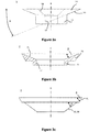
FIGURE 3a is a side view of the first clamping member according to first embodiment shown inFigure 1 ; -
FIGURE 3b is a cross-section of the second clamping member of the first embodiment shown inFigure 1 ; and -
FIGURE 3c is a side view of the cutting blade of the first embodiment shown inFigure 1 . - As can be derived from
Figures 1 and 2 , the new cutter for wood chipping machines is a multi-part cutter assembly. The cutter 1 comprises acutting blade 3. Thecutting blade 3 is constructed as a disc shaped cutting blade and has a substantiallycircular cutting edge 31 extending circumferentially around anannular base portion 33. As will be described in more detail below, theannular blade portion 33 extends at an angle with respect to its central axis D, which corresponds to angles of the clamping members. Thecutting blade 3 further comprises acentral opening 35 extending through the central part of thebase portion 33. - The cutter 1 further comprises a
first clamping member 5. Thefirst clamping member 5, which is better shown inFigure 3a , comprises a generally annular shapedstem portion 51 and a frustro-conical portion 53 projecting radially therefrom. The frustro-conical portion 53 has an inclined side edge, which is constructed as acontact surface 55 for engaging thebase portion 33 of the cutting blade. Acentral opening 57 extends through thefirst clamping member 5 along the central axis B of thefirst clamping member 5. A first end of thecentral opening 57, at the frustro-conical portion 53 of thefirst clamping member 5 has a countersunkbore 58, as can be derived fromFigure 3a . - The cutter 1 also comprises a
second clamping member 7. Thesecond clamping member 7 comprises astem portion 71 and a generally frustro-conical or bowl shapedportion 73 protruding radially from thestem portion 71. The bowl shapedportion 73 defines an inclined contact surface, at a top end surface. Thecontact surface 75 is adapted to engage thebase portion 33 of thecutting blade 3 in close contact. Thesecond clamping member 7 further comprises acentral opening 77 extending through thestem portion 71. - The cutter assembly further comprises a
fastening member 9, which is depicted as a countersunk pin inFigures 1 and 2 . Of course, thefastening member 9 may also be constructed as a fastening screw and is used to secure the cutter to a fly-wheel of the chopping machine. - With reference to
Figure 2 , it can be seen that thestem portion 51 of the first clamping member has an outer diameter fitted to the diameter of thecentral openings cutting blade 3 and thesecond clamping member 7. According to the invention, thecutting blade 3 and thesecond clamping member 7 are aligned with thefirst clamping member 5 by simply slipping them over the outer diameter ofstem portion 51. Once thecutting blade 3 and thesecond clamping member 7 are slipped overstem portion 51, thebody portion 33 ofcutting blade 3 is clamped between thefirst clamping member 5 and thesecond clamping member 7. In more detail, thefirst contact surface 55 of thefirst clamping member 5, engages a first, upper contact surface 37 of thebody portion 33, while thecontact surface 75 of thesecond clamping member 7 engages a second, lower contact surface 38 of thebody portion 33. To facilitate easy alignment of the contactingsurfaces body portion 33 has a constant thickness. As such, the first contact surface 37 and the second contact surface 38 are inclined at identical angles, which correspond to angles of inclination of the contact surfaces 55 and 75 of the first andsecond clamping members - The angles of inclination, alpha, beta, gamma of the contact surfaces 55, 75, 37 and 38 can be derived from
Figures 3a to 3c . All of the contact surfaces 55, 75, 37, 38 have the same inclination and extend at an α, β or y of 10 to 30, more preferably 20 to 25 degrees with respect to a horizontal axis shown inFigures 3a to 3c . In other words, the contact surfaces 55, 75, 37, 38 are all inclined at the same angle of 60 to 80 degrees, more preferably 65 to 70 degrees with respect to the central axis B, C or D respectively. - The
circular cutting edge 31 of thecutting blade 3 preferably extends at an angle δ of 40 to 50 degrees with respect to the horizontal axis inFigure 3c , and thus also with respect to the central axis D of thecutting blade 3. - The
cutting blade 3, thefirst clamping member 5 and thesecond clamping member 7 are produced from steel, preferably steel alloys. Whilst the first andsecond clamping members cutting blade 3 from hardened steel, such as 27NNCRB5-2. This is because only thecutting edge 31 comes into contact with the wood material during normal use. The new,thinner cutting blade 3 can be re-sharpened easily, even without specialist sharpening tools. To this end, thecutting blade 3 can be dismounted from the first andsecond clamping members entire edge 31 of thecutting blade 3 is worn off and re-sharpening is no longer a possibility, thecutting blade 3 can be replaced, while the mounting structure, consisting of the first andsecond clamping members stem portion 71 of the second clamping member, which need to fit exactly into corresponding cavities of the fly-wheel (not shown). Accordingly, the new multi-part cutter 1 is significantly more cost effective in production and thus can reduce costs by up to 60%.
Claims (12)
- A cutter (1) for wood chipping machines, the cutter (1) comprising:• a substantially disc-shaped cutting blade (3) comprising at least one cutting edge (31) and defining a central opening therethrough• a mounting structure adapted to removably attach the substantially disc-shaped cutting blade (3) to a wood chipping machine, the mounting structure comprising first (5) and second (7) clamping members adapted to clamp the cutting blade (3) therebetween, each clamping member (5, 7) defining a respective central opening therethrough wherein the central openings in the clamping members (5, 7) and the blade (3) are arranged such that when the blade (3) is clamped between the clamping members (5, 7), the central openings are aligned; and• a fastening member (9) which extends through the central openings and is configured to secure the clamping members (5, 7) and blade (3) to the wood chipping machine and thereby facilitate clamping of the blade (3) between the clamping members (5, 7).
- The cutter (1) of claim 1, wherein the first clamping member (5) comprises a stem portion (51) and a frusto-conical portion (53) protruding radially from the stem portion (51).
- The cutter (1) of claim 2, wherein the opening in the second clamping member (7) comprises a central opening (77) adapted to receive the stem portion (51) of the first clamping member (5).
- The cutter (1) of claim 2 or 3, wherein the opening (77) in the substantially disc shaped cutting blade (3) comprises a central opening (35) adapted to receive the stem portion (51) of the first clamping member (5).
- The cutter (1) of any of claims 1 to 4, wherein the second clamping member (7) comprises a stem portion (71) adapted to be received in a corresponding cavity of the wood chipping machine and a substantially frusto-conical portion (73) protruding radially from the stem portion (71).
- The cutter (1) of claim 2 in combination with claim 5, wherein the substantially disc shaped cutting blade (3) is adapted to be received between the frusto-conical portions (53, 73) of the first (5) and second (7) clamping members.
- The cutter (1) of claim 6, wherein the substantially disc shaped cutting blade (3) comprises a circular cutting edge.
- The cutter (1) of any of claims 1 to 7, wherein the first (5) and second (7) clamping members are of a first material, which is different from a second material of the substantially disc shaped cutting blade (3).
- The cutter (1) of claim 8, wherein the first (5) and second (7) clamping members are made from steel.
- The cutter (1) of claim 8 or 9, wherein the substantially disc-shaped cutting blade is made from hardened steel.
- A flywheel for wood chipping machines, the flywheel comprising a rotor disc and a plurality of cutters according to any of claims 1 to 10, the cutters being removably attached to the rotor disc.
- A wood chipping machine comprising the flywheel of claim 11.
Applications Claiming Priority (1)
| Application Number | Priority Date | Filing Date | Title |
|---|---|---|---|
| GB1615355.3A GB2553567A (en) | 2016-09-09 | 2016-09-09 | Cutter and fly-wheel for wood chipping machines |
Publications (2)
| Publication Number | Publication Date |
|---|---|
| EP3292967A1 EP3292967A1 (en) | 2018-03-14 |
| EP3292967B1 true EP3292967B1 (en) | 2020-10-28 |
Family
ID=57234774
Family Applications (1)
| Application Number | Title | Priority Date | Filing Date |
|---|---|---|---|
| EP17189581.6A Active EP3292967B1 (en) | 2016-09-09 | 2017-09-06 | Cutter and fly-wheel for wood chipping machines |
Country Status (2)
| Country | Link |
|---|---|
| EP (1) | EP3292967B1 (en) |
| GB (1) | GB2553567A (en) |
Citations (2)
| Publication number | Priority date | Publication date | Assignee | Title |
|---|---|---|---|---|
| US3266539A (en) * | 1964-03-18 | 1966-08-16 | Oliver P Gantt | Self-sharpening chipper |
| EP0903182A1 (en) * | 1997-08-19 | 1999-03-24 | Turner Development Limited | Shredder |
Family Cites Families (7)
| Publication number | Priority date | Publication date | Assignee | Title |
|---|---|---|---|---|
| US4736781A (en) * | 1986-08-26 | 1988-04-12 | Morbark Industries, Inc. | Stump disintegrator |
| US5271442B1 (en) * | 1993-02-19 | 1996-05-07 | Commercial Knife Inc | Knife with clamp package mounting knife |
| US5439039A (en) * | 1994-08-30 | 1995-08-08 | Pacific Saw And Knife Company | Slabber with fixed counterknife and adjustable knife and clamp |
| DE19619345A1 (en) * | 1996-05-14 | 1997-11-20 | Maier Zerkleinerungstech Gmbh | Chipper for wood chips |
| US6257511B1 (en) * | 1997-08-15 | 2001-07-10 | Anthony L. Turner | Wood-chipping machines |
| US5979522A (en) * | 1998-11-18 | 1999-11-09 | Key Knife, Inc. | Knife holder for a chipper disc |
| US6662837B2 (en) * | 2001-07-16 | 2003-12-16 | Paul M. Smith | Replaceable blades for wood chippers |
-
2016
- 2016-09-09 GB GB1615355.3A patent/GB2553567A/en not_active Withdrawn
-
2017
- 2017-09-06 EP EP17189581.6A patent/EP3292967B1/en active Active
Patent Citations (2)
| Publication number | Priority date | Publication date | Assignee | Title |
|---|---|---|---|---|
| US3266539A (en) * | 1964-03-18 | 1966-08-16 | Oliver P Gantt | Self-sharpening chipper |
| EP0903182A1 (en) * | 1997-08-19 | 1999-03-24 | Turner Development Limited | Shredder |
Also Published As
| Publication number | Publication date |
|---|---|
| EP3292967A1 (en) | 2018-03-14 |
| GB201615355D0 (en) | 2016-10-26 |
| GB2553567A (en) | 2018-03-14 |
Similar Documents
| Publication | Publication Date | Title |
|---|---|---|
| US8534580B2 (en) | Granulator blade | |
| EP2799144B1 (en) | Cutter assembly and adjustable cutter for use in comminuting apparatus | |
| US10646880B2 (en) | Cutting tooth splitter apparatus and method | |
| US9168599B2 (en) | Saw disk with improved chip discharge | |
| US7004413B2 (en) | Grinder cutter tooth and anvil assembly | |
| WO2008057027A1 (en) | Pair of saw blades | |
| US20090008488A1 (en) | Comminution rotor for producing wood chips | |
| US11084043B2 (en) | Impact cutter blade and holder system and method | |
| US6196106B1 (en) | Tree felling disc saw with replaceable arcuate teeth | |
| US5961057A (en) | Wood chipping machines | |
| US4463907A (en) | Cutter wheel for brush chipper | |
| EP0480759A1 (en) | Stump chipper knife assembly | |
| US6257511B1 (en) | Wood-chipping machines | |
| EP3292967B1 (en) | Cutter and fly-wheel for wood chipping machines | |
| US9227192B2 (en) | Chipper striker assembly | |
| CA2758892C (en) | Saw disk with improved chip discharge | |
| US6848640B2 (en) | Device for comminuting material and knife support plate | |
| US20190344367A1 (en) | Saw tooth holder, cutting disk for a rotary cutting machine and rotary cutting machine including same | |
| US20020185195A1 (en) | Wood pulverizer with improved grates and grate components | |
| US20100108195A1 (en) | Debarking apparatus | |
| FI126483B (en) | Blade for circular saw and cleaning element | |
| EP2799142A1 (en) | Mounting block for attaching a reducing element to a rotary drum | |
| KR200248137Y1 (en) | crush drum of wood crusher | |
| CA2251902A1 (en) | Tree felling disc saw with replacable arcuate teeth | |
| US619530A (en) | Benjamin s |
Legal Events
| Date | Code | Title | Description |
|---|---|---|---|
| PUAI | Public reference made under article 153(3) epc to a published international application that has entered the european phase |
Free format text: ORIGINAL CODE: 0009012 |
|
| STAA | Information on the status of an ep patent application or granted ep patent |
Free format text: STATUS: THE APPLICATION HAS BEEN PUBLISHED |
|
| AK | Designated contracting states |
Kind code of ref document: A1 Designated state(s): AL AT BE BG CH CY CZ DE DK EE ES FI FR GB GR HR HU IE IS IT LI LT LU LV MC MK MT NL NO PL PT RO RS SE SI SK SM TR |
|
| AX | Request for extension of the european patent |
Extension state: BA ME |
|
| STAA | Information on the status of an ep patent application or granted ep patent |
Free format text: STATUS: REQUEST FOR EXAMINATION WAS MADE |
|
| 17P | Request for examination filed |
Effective date: 20180910 |
|
| RBV | Designated contracting states (corrected) |
Designated state(s): AL AT BE BG CH CY CZ DE DK EE ES FI FR GB GR HR HU IE IS IT LI LT LU LV MC MK MT NL NO PL PT RO RS SE SI SK SM TR |
|
| STAA | Information on the status of an ep patent application or granted ep patent |
Free format text: STATUS: EXAMINATION IS IN PROGRESS |
|
| 17Q | First examination report despatched |
Effective date: 20190325 |
|
| GRAP | Despatch of communication of intention to grant a patent |
Free format text: ORIGINAL CODE: EPIDOSNIGR1 |
|
| STAA | Information on the status of an ep patent application or granted ep patent |
Free format text: STATUS: GRANT OF PATENT IS INTENDED |
|
| INTG | Intention to grant announced |
Effective date: 20200417 |
|
| GRAS | Grant fee paid |
Free format text: ORIGINAL CODE: EPIDOSNIGR3 |
|
| GRAA | (expected) grant |
Free format text: ORIGINAL CODE: 0009210 |
|
| STAA | Information on the status of an ep patent application or granted ep patent |
Free format text: STATUS: THE PATENT HAS BEEN GRANTED |
|
| AK | Designated contracting states |
Kind code of ref document: B1 Designated state(s): AL AT BE BG CH CY CZ DE DK EE ES FI FR GB GR HR HU IE IS IT LI LT LU LV MC MK MT NL NO PL PT RO RS SE SI SK SM TR |
|
| REG | Reference to a national code |
Ref country code: GB Ref legal event code: FG4D |
|
| REG | Reference to a national code |
Ref country code: CH Ref legal event code: EP |
|
| REG | Reference to a national code |
Ref country code: DE Ref legal event code: R096 Ref document number: 602017026215 Country of ref document: DE |
|
| REG | Reference to a national code |
Ref country code: AT Ref legal event code: REF Ref document number: 1327753 Country of ref document: AT Kind code of ref document: T Effective date: 20201115 |
|
| REG | Reference to a national code |
Ref country code: IE Ref legal event code: FG4D |
|
| REG | Reference to a national code |
Ref country code: AT Ref legal event code: MK05 Ref document number: 1327753 Country of ref document: AT Kind code of ref document: T Effective date: 20201028 |
|
| REG | Reference to a national code |
Ref country code: NL Ref legal event code: MP Effective date: 20201028 |
|
| PG25 | Lapsed in a contracting state [announced via postgrant information from national office to epo] |
Ref country code: RS Free format text: LAPSE BECAUSE OF FAILURE TO SUBMIT A TRANSLATION OF THE DESCRIPTION OR TO PAY THE FEE WITHIN THE PRESCRIBED TIME-LIMIT Effective date: 20201028 Ref country code: PT Free format text: LAPSE BECAUSE OF FAILURE TO SUBMIT A TRANSLATION OF THE DESCRIPTION OR TO PAY THE FEE WITHIN THE PRESCRIBED TIME-LIMIT Effective date: 20210301 Ref country code: NO Free format text: LAPSE BECAUSE OF FAILURE TO SUBMIT A TRANSLATION OF THE DESCRIPTION OR TO PAY THE FEE WITHIN THE PRESCRIBED TIME-LIMIT Effective date: 20210128 Ref country code: NL Free format text: LAPSE BECAUSE OF FAILURE TO SUBMIT A TRANSLATION OF THE DESCRIPTION OR TO PAY THE FEE WITHIN THE PRESCRIBED TIME-LIMIT Effective date: 20201028 Ref country code: FI Free format text: LAPSE BECAUSE OF FAILURE TO SUBMIT A TRANSLATION OF THE DESCRIPTION OR TO PAY THE FEE WITHIN THE PRESCRIBED TIME-LIMIT Effective date: 20201028 Ref country code: GR Free format text: LAPSE BECAUSE OF FAILURE TO SUBMIT A TRANSLATION OF THE DESCRIPTION OR TO PAY THE FEE WITHIN THE PRESCRIBED TIME-LIMIT Effective date: 20210129 |
|
| REG | Reference to a national code |
Ref country code: LT Ref legal event code: MG4D |
|
| PG25 | Lapsed in a contracting state [announced via postgrant information from national office to epo] |
Ref country code: AT Free format text: LAPSE BECAUSE OF FAILURE TO SUBMIT A TRANSLATION OF THE DESCRIPTION OR TO PAY THE FEE WITHIN THE PRESCRIBED TIME-LIMIT Effective date: 20201028 Ref country code: ES Free format text: LAPSE BECAUSE OF FAILURE TO SUBMIT A TRANSLATION OF THE DESCRIPTION OR TO PAY THE FEE WITHIN THE PRESCRIBED TIME-LIMIT Effective date: 20201028 Ref country code: BG Free format text: LAPSE BECAUSE OF FAILURE TO SUBMIT A TRANSLATION OF THE DESCRIPTION OR TO PAY THE FEE WITHIN THE PRESCRIBED TIME-LIMIT Effective date: 20210128 Ref country code: IS Free format text: LAPSE BECAUSE OF FAILURE TO SUBMIT A TRANSLATION OF THE DESCRIPTION OR TO PAY THE FEE WITHIN THE PRESCRIBED TIME-LIMIT Effective date: 20210228 Ref country code: PL Free format text: LAPSE BECAUSE OF FAILURE TO SUBMIT A TRANSLATION OF THE DESCRIPTION OR TO PAY THE FEE WITHIN THE PRESCRIBED TIME-LIMIT Effective date: 20201028 Ref country code: LV Free format text: LAPSE BECAUSE OF FAILURE TO SUBMIT A TRANSLATION OF THE DESCRIPTION OR TO PAY THE FEE WITHIN THE PRESCRIBED TIME-LIMIT Effective date: 20201028 Ref country code: SE Free format text: LAPSE BECAUSE OF FAILURE TO SUBMIT A TRANSLATION OF THE DESCRIPTION OR TO PAY THE FEE WITHIN THE PRESCRIBED TIME-LIMIT Effective date: 20201028 |
|
| PG25 | Lapsed in a contracting state [announced via postgrant information from national office to epo] |
Ref country code: HR Free format text: LAPSE BECAUSE OF FAILURE TO SUBMIT A TRANSLATION OF THE DESCRIPTION OR TO PAY THE FEE WITHIN THE PRESCRIBED TIME-LIMIT Effective date: 20201028 |
|
| REG | Reference to a national code |
Ref country code: DE Ref legal event code: R097 Ref document number: 602017026215 Country of ref document: DE |
|
| PG25 | Lapsed in a contracting state [announced via postgrant information from national office to epo] |
Ref country code: SK Free format text: LAPSE BECAUSE OF FAILURE TO SUBMIT A TRANSLATION OF THE DESCRIPTION OR TO PAY THE FEE WITHIN THE PRESCRIBED TIME-LIMIT Effective date: 20201028 Ref country code: RO Free format text: LAPSE BECAUSE OF FAILURE TO SUBMIT A TRANSLATION OF THE DESCRIPTION OR TO PAY THE FEE WITHIN THE PRESCRIBED TIME-LIMIT Effective date: 20201028 Ref country code: CZ Free format text: LAPSE BECAUSE OF FAILURE TO SUBMIT A TRANSLATION OF THE DESCRIPTION OR TO PAY THE FEE WITHIN THE PRESCRIBED TIME-LIMIT Effective date: 20201028 Ref country code: EE Free format text: LAPSE BECAUSE OF FAILURE TO SUBMIT A TRANSLATION OF THE DESCRIPTION OR TO PAY THE FEE WITHIN THE PRESCRIBED TIME-LIMIT Effective date: 20201028 Ref country code: LT Free format text: LAPSE BECAUSE OF FAILURE TO SUBMIT A TRANSLATION OF THE DESCRIPTION OR TO PAY THE FEE WITHIN THE PRESCRIBED TIME-LIMIT Effective date: 20201028 Ref country code: SM Free format text: LAPSE BECAUSE OF FAILURE TO SUBMIT A TRANSLATION OF THE DESCRIPTION OR TO PAY THE FEE WITHIN THE PRESCRIBED TIME-LIMIT Effective date: 20201028 |
|
| PG25 | Lapsed in a contracting state [announced via postgrant information from national office to epo] |
Ref country code: DK Free format text: LAPSE BECAUSE OF FAILURE TO SUBMIT A TRANSLATION OF THE DESCRIPTION OR TO PAY THE FEE WITHIN THE PRESCRIBED TIME-LIMIT Effective date: 20201028 |
|
| PLBE | No opposition filed within time limit |
Free format text: ORIGINAL CODE: 0009261 |
|
| STAA | Information on the status of an ep patent application or granted ep patent |
Free format text: STATUS: NO OPPOSITION FILED WITHIN TIME LIMIT |
|
| 26N | No opposition filed |
Effective date: 20210729 |
|
| PG25 | Lapsed in a contracting state [announced via postgrant information from national office to epo] |
Ref country code: AL Free format text: LAPSE BECAUSE OF FAILURE TO SUBMIT A TRANSLATION OF THE DESCRIPTION OR TO PAY THE FEE WITHIN THE PRESCRIBED TIME-LIMIT Effective date: 20201028 Ref country code: IT Free format text: LAPSE BECAUSE OF FAILURE TO SUBMIT A TRANSLATION OF THE DESCRIPTION OR TO PAY THE FEE WITHIN THE PRESCRIBED TIME-LIMIT Effective date: 20201028 |
|
| PG25 | Lapsed in a contracting state [announced via postgrant information from national office to epo] |
Ref country code: SI Free format text: LAPSE BECAUSE OF FAILURE TO SUBMIT A TRANSLATION OF THE DESCRIPTION OR TO PAY THE FEE WITHIN THE PRESCRIBED TIME-LIMIT Effective date: 20201028 |
|
| REG | Reference to a national code |
Ref country code: CH Ref legal event code: PL |
|
| REG | Reference to a national code |
Ref country code: BE Ref legal event code: MM Effective date: 20210930 |
|
| PG25 | Lapsed in a contracting state [announced via postgrant information from national office to epo] |
Ref country code: IS Free format text: LAPSE BECAUSE OF FAILURE TO SUBMIT A TRANSLATION OF THE DESCRIPTION OR TO PAY THE FEE WITHIN THE PRESCRIBED TIME-LIMIT Effective date: 20210228 Ref country code: MC Free format text: LAPSE BECAUSE OF FAILURE TO SUBMIT A TRANSLATION OF THE DESCRIPTION OR TO PAY THE FEE WITHIN THE PRESCRIBED TIME-LIMIT Effective date: 20201028 |
|
| PG25 | Lapsed in a contracting state [announced via postgrant information from national office to epo] |
Ref country code: LU Free format text: LAPSE BECAUSE OF NON-PAYMENT OF DUE FEES Effective date: 20210906 Ref country code: IE Free format text: LAPSE BECAUSE OF NON-PAYMENT OF DUE FEES Effective date: 20210906 Ref country code: BE Free format text: LAPSE BECAUSE OF NON-PAYMENT OF DUE FEES Effective date: 20210930 |
|
| PG25 | Lapsed in a contracting state [announced via postgrant information from national office to epo] |
Ref country code: LI Free format text: LAPSE BECAUSE OF NON-PAYMENT OF DUE FEES Effective date: 20210930 Ref country code: CH Free format text: LAPSE BECAUSE OF NON-PAYMENT OF DUE FEES Effective date: 20210930 |
|
| PG25 | Lapsed in a contracting state [announced via postgrant information from national office to epo] |
Ref country code: HU Free format text: LAPSE BECAUSE OF FAILURE TO SUBMIT A TRANSLATION OF THE DESCRIPTION OR TO PAY THE FEE WITHIN THE PRESCRIBED TIME-LIMIT; INVALID AB INITIO Effective date: 20170906 |
|
| PG25 | Lapsed in a contracting state [announced via postgrant information from national office to epo] |
Ref country code: CY Free format text: LAPSE BECAUSE OF FAILURE TO SUBMIT A TRANSLATION OF THE DESCRIPTION OR TO PAY THE FEE WITHIN THE PRESCRIBED TIME-LIMIT Effective date: 20201028 |
|
| PGFP | Annual fee paid to national office [announced via postgrant information from national office to epo] |
Ref country code: GB Payment date: 20230913 Year of fee payment: 7 |
|
| PGFP | Annual fee paid to national office [announced via postgrant information from national office to epo] |
Ref country code: FR Payment date: 20230928 Year of fee payment: 7 Ref country code: DE Payment date: 20230920 Year of fee payment: 7 |