EP3292887B1 - Expulsion of a fire suppressant from a container - Google Patents
Expulsion of a fire suppressant from a container Download PDFInfo
- Publication number
- EP3292887B1 EP3292887B1 EP17184714.8A EP17184714A EP3292887B1 EP 3292887 B1 EP3292887 B1 EP 3292887B1 EP 17184714 A EP17184714 A EP 17184714A EP 3292887 B1 EP3292887 B1 EP 3292887B1
- Authority
- EP
- European Patent Office
- Prior art keywords
- container
- pressure
- propellant gas
- fire
- fire suppressant
- Prior art date
- Legal status (The legal status is an assumption and is not a legal conclusion. Google has not performed a legal analysis and makes no representation as to the accuracy of the status listed.)
- Active
Links
- 239000003380 propellant Substances 0.000 claims description 79
- 238000000034 method Methods 0.000 claims description 55
- 230000001629 suppression Effects 0.000 claims description 28
- 238000009826 distribution Methods 0.000 claims description 26
- 230000004044 response Effects 0.000 claims description 18
- 239000007791 liquid phase Substances 0.000 claims description 8
- 239000007787 solid Substances 0.000 claims description 8
- 239000002243 precursor Substances 0.000 claims description 7
- 239000000779 smoke Substances 0.000 claims description 6
- 230000000977 initiatory effect Effects 0.000 claims description 4
- 238000006243 chemical reaction Methods 0.000 claims description 3
- 238000012544 monitoring process Methods 0.000 claims description 2
- 238000007789 sealing Methods 0.000 claims description 2
- 239000007789 gas Substances 0.000 description 93
- 239000003795 chemical substances by application Substances 0.000 description 11
- 239000007788 liquid Substances 0.000 description 8
- 239000006260 foam Substances 0.000 description 7
- 238000003860 storage Methods 0.000 description 7
- 239000011261 inert gas Substances 0.000 description 6
- 238000010586 diagram Methods 0.000 description 5
- 230000006870 function Effects 0.000 description 5
- CURLTUGMZLYLDI-UHFFFAOYSA-N Carbon dioxide Chemical compound O=C=O CURLTUGMZLYLDI-UHFFFAOYSA-N 0.000 description 4
- 239000000203 mixture Substances 0.000 description 4
- 230000008569 process Effects 0.000 description 4
- 230000007423 decrease Effects 0.000 description 3
- 230000001419 dependent effect Effects 0.000 description 3
- 238000013461 design Methods 0.000 description 3
- 238000005259 measurement Methods 0.000 description 3
- XKRFYHLGVUSROY-UHFFFAOYSA-N Argon Chemical compound [Ar] XKRFYHLGVUSROY-UHFFFAOYSA-N 0.000 description 2
- 229920004449 Halon® Polymers 0.000 description 2
- 239000001569 carbon dioxide Substances 0.000 description 2
- 229910002092 carbon dioxide Inorganic materials 0.000 description 2
- 238000001514 detection method Methods 0.000 description 2
- PXBRQCKWGAHEHS-UHFFFAOYSA-N dichlorodifluoromethane Chemical compound FC(F)(Cl)Cl PXBRQCKWGAHEHS-UHFFFAOYSA-N 0.000 description 2
- 230000000694 effects Effects 0.000 description 2
- 238000001704 evaporation Methods 0.000 description 2
- 239000012528 membrane Substances 0.000 description 2
- 239000002184 metal Substances 0.000 description 2
- 238000012986 modification Methods 0.000 description 2
- 230000004048 modification Effects 0.000 description 2
- 239000004449 solid propellant Substances 0.000 description 2
- IJGRMHOSHXDMSA-UHFFFAOYSA-N Atomic nitrogen Chemical compound N#N IJGRMHOSHXDMSA-UHFFFAOYSA-N 0.000 description 1
- 238000013459 approach Methods 0.000 description 1
- 229910052786 argon Inorganic materials 0.000 description 1
- 230000033228 biological regulation Effects 0.000 description 1
- 238000001816 cooling Methods 0.000 description 1
- 238000007599 discharging Methods 0.000 description 1
- 239000012530 fluid Substances 0.000 description 1
- 150000008282 halocarbons Chemical class 0.000 description 1
- 238000009434 installation Methods 0.000 description 1
- 230000007774 longterm Effects 0.000 description 1
- 238000004519 manufacturing process Methods 0.000 description 1
- 239000000463 material Substances 0.000 description 1
- JCXJVPUVTGWSNB-UHFFFAOYSA-N nitrogen dioxide Inorganic materials O=[N]=O JCXJVPUVTGWSNB-UHFFFAOYSA-N 0.000 description 1
- 230000003287 optical effect Effects 0.000 description 1
- 230000002085 persistent effect Effects 0.000 description 1
- 239000012071 phase Substances 0.000 description 1
- 239000000843 powder Substances 0.000 description 1
- 230000009711 regulatory function Effects 0.000 description 1
- 239000007921 spray Substances 0.000 description 1
- 230000000153 supplemental effect Effects 0.000 description 1
- 230000001960 triggered effect Effects 0.000 description 1
- 239000012808 vapor phase Substances 0.000 description 1
- -1 vapors Substances 0.000 description 1
Images


Classifications
-
- A—HUMAN NECESSITIES
- A62—LIFE-SAVING; FIRE-FIGHTING
- A62C—FIRE-FIGHTING
- A62C35/00—Permanently-installed equipment
- A62C35/02—Permanently-installed equipment with containers for delivering the extinguishing substance
- A62C35/023—Permanently-installed equipment with containers for delivering the extinguishing substance the extinguishing material being expelled by compressed gas, taken from storage tanks, or by generating a pressure gas
-
- A—HUMAN NECESSITIES
- A62—LIFE-SAVING; FIRE-FIGHTING
- A62C—FIRE-FIGHTING
- A62C31/00—Delivery of fire-extinguishing material
-
- A—HUMAN NECESSITIES
- A62—LIFE-SAVING; FIRE-FIGHTING
- A62C—FIRE-FIGHTING
- A62C13/00—Portable extinguishers which are permanently pressurised or pressurised immediately before use
- A62C13/003—Extinguishers with spraying and projection of extinguishing agents by pressurised gas
-
- A—HUMAN NECESSITIES
- A62—LIFE-SAVING; FIRE-FIGHTING
- A62C—FIRE-FIGHTING
- A62C3/00—Fire prevention, containment or extinguishing specially adapted for particular objects or places
- A62C3/07—Fire prevention, containment or extinguishing specially adapted for particular objects or places in vehicles, e.g. in road vehicles
-
- A—HUMAN NECESSITIES
- A62—LIFE-SAVING; FIRE-FIGHTING
- A62C—FIRE-FIGHTING
- A62C31/00—Delivery of fire-extinguishing material
- A62C31/28—Accessories for delivery devices, e.g. supports
-
- A—HUMAN NECESSITIES
- A62—LIFE-SAVING; FIRE-FIGHTING
- A62C—FIRE-FIGHTING
- A62C35/00—Permanently-installed equipment
- A62C35/02—Permanently-installed equipment with containers for delivering the extinguishing substance
- A62C35/11—Permanently-installed equipment with containers for delivering the extinguishing substance controlled by a signal from the danger zone
- A62C35/13—Permanently-installed equipment with containers for delivering the extinguishing substance controlled by a signal from the danger zone with a finite supply of extinguishing material
-
- A—HUMAN NECESSITIES
- A62—LIFE-SAVING; FIRE-FIGHTING
- A62C—FIRE-FIGHTING
- A62C37/00—Control of fire-fighting equipment
- A62C37/04—Control of fire-fighting equipment with electrically-controlled release
-
- A—HUMAN NECESSITIES
- A62—LIFE-SAVING; FIRE-FIGHTING
- A62C—FIRE-FIGHTING
- A62C37/00—Control of fire-fighting equipment
- A62C37/36—Control of fire-fighting equipment an actuating signal being generated by a sensor separate from an outlet device
-
- F—MECHANICAL ENGINEERING; LIGHTING; HEATING; WEAPONS; BLASTING
- F16—ENGINEERING ELEMENTS AND UNITS; GENERAL MEASURES FOR PRODUCING AND MAINTAINING EFFECTIVE FUNCTIONING OF MACHINES OR INSTALLATIONS; THERMAL INSULATION IN GENERAL
- F16K—VALVES; TAPS; COCKS; ACTUATING-FLOATS; DEVICES FOR VENTING OR AERATING
- F16K17/00—Safety valves; Equalising valves, e.g. pressure relief valves
- F16K17/40—Safety valves; Equalising valves, e.g. pressure relief valves with a fracturing member, e.g. fracturing diaphragm, glass, fusible joint
- F16K17/403—Safety valves; Equalising valves, e.g. pressure relief valves with a fracturing member, e.g. fracturing diaphragm, glass, fusible joint with a fracturing valve member
Definitions
- the present disclosure generally relates to methods and systems for expelling a fire suppressant from a container, and more particularly to methods and systems for expelling a fire suppressant from a container by flowing a propellant gas into the container.
- WO 2013/028053 in accordance with its abstract, states a fire extinguishing system that comprises a hermetically sealed storage canister fabricated with at least one gas outlet and defining a hollow within; a powder form fire extinguishing agent stored inside the canister; a solid propellant, which is ignitable to generate gases; connected to the canister; and a rupturable seal disposed at the gas outlet, wherein the solid propellant generates gasses to aerate the fire extinguishing agent inside the canister and build a positive gas pressure until the gas pressure is sufficient to rupture the seal for discharging the fire extinguishing agent under pressurized gas flow.
- the fire suppression system has advantages when compared to conventional fire suppression systems. Whereas a conventional fire suppression system typically stores the energy to be used for expelling the fire suppressant within the container itself, the fire suppression system disclosed herein may store most of this energy outside of the container within one or more solid precursors of the propellant gas. Storing the energy in a solid form within the gas generator instead of as vapor pressure within the container allows for the container to have a reduced volume and a reduced wall thickness. Also, since the vapor pressure of the fire suppressant or another propellant gas that is pre-filled into the container is no longer the primary energy source for expelling the fire suppressant, fire suppressants having lower vapor pressures may be used.
- the distribution manifold 114 is coupled to the container 102 via the port 108 and the rupture disc 116.
- the distribution manifold 114 may include a network of pipes configured to distribute the expelled fire suppressant 104 to various areas of interest.
- the method 200 includes, in response to the pressure within the container exceeding a threshold pressure, expelling the fire suppressant from a second port of the container into the distribution manifold.
- the generated propellant gas continues to flow into the container via the first port at least until substantially all of the fire suppressant included within the container prior to the generation of the propellant gas is expelled from the container via the second port.
- the propellant gas 112 continues to flow into the container 102 and the pressure within the container 102 increases to exceed a predetermined threshold pressure.
- the rupture disc 116 ruptures and the pressure within the container 102 begins to expel the fire suppressant 104 from the container 102 via the port 108 into the distribution manifold 114, as shown in Figure 11 .
- the threshold pressure may be a pressure within a range of 62,05 bar (900 pounds per square inch gauge (psig)) and 75,84 bar (1100 psig). More specifically, the threshold pressure may be substantially equal to 68,95 bar (1000 psig). That is, the method 200 may further involve expelling the fire suppressant 104 in response to the pressure within the container 102 exceeding a pressure within a range of 62,05 bar (900 psig) and 75,84 bar (1100 psig), or more specifically, the method 200 may further involve expelling the fire suppressant 104 in response to the pressure within the container 102 exceeding a pressure that is substantially equal to 68,95 bar (1000 psig).
- the propellant gas 112 continues to flow into the container 102 via the port 106 at least until substantially all of the fire suppressant 104 is expelled from the container 102 via the port 108.
- Figure 12 shows that the propellant gas 112 continues to flow into the container 102 after the fire suppressant 104 has been fully or nearly expelled from the container 102.
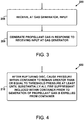
- Figure 3 is a block diagram of the method 300.
- the method 300 includes receiving, at the gas generator, an input.
- the gas generator 110 may receive the input from the control unit 122, for example.
- the control unit 122 may include a heat detector 122, a smoke detector 122, or a user interface 122, but other examples are possible.
- the method 300 includes generating the propellant gas in response to receiving the input at the gas generator.
- Figure 8 shows the gas generator 110 beginning to generate the propellant gas 112 in response to the gas generator 110 receiving an input from the control unit 122.
- the gas generator 110 may mix one or more solid precursors of the propellant gas 112 in response to receiving the input.
- Figure 4 is a block diagram of the method 400.
- the method 400 includes, after rupturing the disc, causing the pressure within the container to remain greater than or equal to the threshold pressure at least until substantially all of the fire suppressant included within the container prior to the generation of the propellant gas is expelled from the container.
- the gas generator 110 continues to produce the propellant gas 112 and flow the propellant gas 112 into the container 102 at least until the fire suppressant 104 has been substantially expelled from the container 102.
- the ruptured disc 116 may perform a regulation function whereby the propellant gas 112 flows into the container 102 at a rate sufficient to maintain the pressure within the container 102 at or above the threshold pressure at least until the fire suppressant 104 has been substantially expelled from the container 102.
- Figure 5 is a block diagram of the method 500.
- the method 500 includes monitoring, via a pressure gauge, the pressure within the container generated at least in part by the second propellant gas.
- a second propellant gas is included within the container prior to the generation of the propellant gas.
- the propellant gas 118 may be filled into the container 102 along with the fire suppressant 104 prior to sealing the container 102.
- the pressure gauge 120 may monitor the pressure within the container 102 prior to, during, and/or after expulsion of the fire suppressant 104.
- the vapor pressure maintained within the container 102 may correspond, at least in part, to the propellant gas 118.
- Figure 6 is block diagram of the method 600.
- the method 600 includes flowing the expelled fire suppressant through the distribution manifold in a liquid phase.
- the method 600 includes dispensing the expelled fire suppressant from the distribution manifold in the liquid phase.
- the continuing generation of the propellant gas 112 maintains a pressure within the container 102 and the distribution manifold 114 sufficient to keep the fire suppressant 104 from evaporating at least until the fire suppressant 104 reaches dispensing nozzles of the distribution manifold 114.
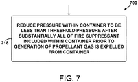
- Figure 7 is a block diagram of the method 700.
- the method 700 includes reducing the pressure within the container to be less than the threshold pressure after substantially all of the fire suppressant included within the container prior to the generation of the propellant gas is expelled from the container. This is discussed in more detail below with reference to Figure 13 .
- Figure 13 graphically depicts the pressure within the container 102 with respect to time.
- the pressure remains somewhat constant at low pressure, as the gas generator 110 has not yet been activated.
- the pressure within the container 102 may primarily correspond to the pre-filled propellant gas 118.
- the gas generator 110 is activated and begins generating the propellant gas 112, and the pressure within the container 102 begins to increase.
- the propellant gas 112 fills into the container 102 and the pressure increases.
- the rupture disc 116 ruptures in response to the pressure within the container 102 exceeding a predetermined threshold pressure.
- the ruptured rupture disc 116 allows the pressure built up in the container 102 to begin to expel some of the fire suppressant 104 out of the port 108.
- the propellant gas 112 continues to fill the container 102 while the fire suppressant 104 continues to be expelled from the container 102.
- the pressure remains somewhat constant at a high pressure during this time (e.g., near the predetermined threshold pressure).
- the gas generator 110 is no longer generating the propellant gas 112, and the pressure begins to decrease as the remainder of the propellant gases and the fire suppressant 104 continue to exit the container 102.
Description
- The present disclosure generally relates to methods and systems for expelling a fire suppressant from a container, and more particularly to methods and systems for expelling a fire suppressant from a container by flowing a propellant gas into the container.
-
US 2007/158085 A1 , in accordance with its abstract, states a fire extinguishing apparatus and method, comprising: a container configured to receive and retain a fire extinguishing agent; a pressure generator coupled to the container to have a generated pressure act upon the fire extinguishing agent to expel the fire extinguishing agent over an expel-exit of the container. Due to a separator which is placed within the container so that the fire extinguishing agent and the pressure generator are separated, it is advantageously possible to provide a pressure effect on the extinguishing agent without any risks of mixing a pressurized gas from the pressure generator and the extinguishing agent, especially by the ignition phase of the pressure generator, wherein only the extinguishing agent has to be expelled out of the container. Furthermore some means related to the separator will be proposed for improving the expelling of the extinguishing agent out of container. -
US 6016874 A , in accordance with its abstract, states a compact, affordable fire extinguishing system that utilizes a combination of compressed inert gas tanks and solid propellent gas generators to provide a blend of inert gases to extinguish fires in an enclosure. The compressed inert gas tanks may contain gases such as argon or carbon dioxide or a combination thereof. The solid propellent gas generators may generate upon initiation either nitrogen or carbon dioxide or a combination thereof. The inert gases from both sources are blended into a composition that will extinguish fires at concentrations that will allow human occupancy during discharge. Such a system can be constructed at a substantially smaller size than conventional compressed gas systems, due to the greater density of the inert gases in the propellent form in storage, which allows greater utility and affordability where installation space is limited or retrofit is desired into prior fire protection systems. -
US2012168184 A1 , in accordance with its abstract, states a fire suppression system for a container including a first tank containing a first liquid component of a two-part foam and a second tank containing a second liquid component of the foam. The system also includes at least one liquid component release device configured to be selectively capable of releasing the first and second components from their respective containers upon receipt of a signal from a fire detector upon detection of a fire. The two-part foam components are propelled through the system by a pressurized propellant that, upon release of the release device, causes the exit of the foam components from their respective tanks, through a mixing conduit to at least one nozzle. The nozzle is configured to spray the liquid component foam mixture into the container wherein the foam cures into a substantially semi-rigid, closed cell foam that is substantially impermeable and may have charring and/or intumescence properties. -
US 3012613 A , in accordance with its introcutory part, states fire extinguishing system for preventing fire by cooling hot metallic parts which, if contacted by a flammable fluid, would cause a fire. -
WO 2013/028053 , in accordance with its abstract, states a fire extinguishing system that comprises a hermetically sealed storage canister fabricated with at least one gas outlet and defining a hollow within; a powder form fire extinguishing agent stored inside the canister; a solid propellant, which is ignitable to generate gases; connected to the canister; and a rupturable seal disposed at the gas outlet, wherein the solid propellant generates gasses to aerate the fire extinguishing agent inside the canister and build a positive gas pressure until the gas pressure is sufficient to rupture the seal for discharging the fire extinguishing agent under pressurized gas flow. - Some fire suppression systems use vapor pressure sealed within a container to expel a liquid fire suppressant from the container into a distribution manifold. The vapor pressure may be maintained by a propellant gas inside of the container and/or the fire suppressant itself. The fire suppressant may be expelled or released in response to receiving an input at a user interface, or in response to an alarm generated by a sensor such as a smoke detector or a heat sensor, for example. This conventional approach has some drawbacks.
- Once the container is filled and sealed to contain the fire suppressant and/or the propellant gas, these liquids and/or vapors are typically stored within the container until the fire suppressant is expelled. The container is generally filled with enough fire suppressant and/or propellant gas such that the vapor pressure within the container is sufficient to discharge the fire suppressant at somewhat cold temperatures. In other situations, the container may be exposed to relatively high temperatures, which may result in the vapor pressure within the container being somewhat high. This means that the container may be designed to have a wall that is thick enough and/or strong enough to contain this high amount of vapor pressure. This may result in the container being heavier and/or larger than the container might otherwise be.
- In addition, conventional fire suppression systems may discharge fire suppressant quite differently depending on the ambient temperature when the discharge occurs. As mentioned above, the vapor pressure within the sealed container will generally be dependent on the ambient temperature. If the ambient temperature is too low when the discharge is triggered, the vapor pressure within the container may be insufficient to sustain a proper discharge of the fire suppressant. That is, some of the fire suppressant may be discharged with insufficient pressure to extinguish a fire. Additionally, at such low discharge pressures, the fire suppressant may evaporate before reaching discharge nozzles, adding further variability. Also, the pressure within the container generally decreases as the fire suppressant and/or the propellant gas exit the container, regardless of the ambient temperature.
- Accordingly, there is a need for a fire suppression system that provides a relatively stable discharge pressure and allows for a smaller and/or lighter fire suppressant container.
- This object is solved by method and system according to the independent claims.
- The features, functions, and advantages that have been discussed can be achieved independently in various examples or may be combined in yet other examples further details of which can be seen with reference to the following description and drawings.
- The novel features believed characteristic of the illustrative examples are set forth in the appended claims. The illustrative examples, however, as well as a preferred mode of use, further objectives and descriptions thereof, will best be understood by reference to the following detailed description of an illustrative example of the present disclosure when read in conjunction with the accompanying Figures.
-
Figure 1 illustrates an example fire suppression system, according to an example . -
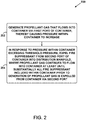
Figure 2 is a flowchart of an example method for expelling a fire suppressant from a container into a distribution manifold, according to an example. -
Figure 3 is a flowchart of another example method for use with the method shown inFigure 2 , according to an example. -
Figure 4 is a flowchart of another example method for use with the method shown inFigure 2 , according to an example. -
Figure 5 is a flowchart of another example method for use with the method shown inFigure 2 , according to an example. -
Figure 6 is a flowchart of another example method for use with the method shown inFigure 2 , according to an example. -
Figure 7 is a flowchart of another example method for use with the method shown inFigure 2 , according to an example. -
Figure 8 illustrates an example fire suppression system, according to an example. -
Figure 9 illustrates an example fire suppression system, according to an example. -
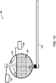
Figure 10 illustrates an example fire suppression system, according to an example. -
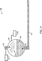
Figure 11 illustrates an example fire suppression system, according to an example. -
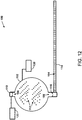
Figure 12 illustrates an example fire suppression system, according to an example. -
Figure 13 graphically depicts, with respect to time, a pressure within a container of an example fire suppression system, according to an example. - Within examples, a fire suppression system includes a container that holds a fire suppressant (i.e.., a liquid fire suppressant). Upon detection of a possible fire, the fire suppression system generates a propellant gas via a gas generator and flows the propellant gas into the container via a first port of the container. As the propellant gas enters the container, the pressure within the container increases. The container also includes a rupture disc that seals a second port of the container. The rupture disc is configured to rupture and release the fire suppressant into a distribution manifold via the second port when the pressure within the container exceeds a threshold pressure. The propellant gas continues to flow into the container until substantially all of the fire suppressant is expelled into the distribution manifold. The distribution manifold may distribute the fire suppressant to various areas for suppression of the possible fire.
- The fire suppression system has advantages when compared to conventional fire suppression systems. Whereas a conventional fire suppression system typically stores the energy to be used for expelling the fire suppressant within the container itself, the fire suppression system disclosed herein may store most of this energy outside of the container within one or more solid precursors of the propellant gas. Storing the energy in a solid form within the gas generator instead of as vapor pressure within the container allows for the container to have a reduced volume and a reduced wall thickness. Also, since the vapor pressure of the fire suppressant or another propellant gas that is pre-filled into the container is no longer the primary energy source for expelling the fire suppressant, fire suppressants having lower vapor pressures may be used.
- Using an energy source that is external to the container may also better regulate the pressure at which the fire suppressant is discharged into the distribution manifold. When vapor pressure stored inside the container is used to expel the fire suppressant, the discharge pressure will generally decrease as the fire suppressant is expelled from the container. This may result in not all of the fire suppressant being expelled from the container and also may result in some of the fire suppressant undesirably evaporating in the distribution manifold before the fire suppressant reaches the possible fire. In the current design, a large amount of externally provided propellant gas coupled with the regulatory function of the rupture disc results in substantially all of the fire suppressant being expelled into the distribution manifold at a relatively constant pressure. The discharge pressure of the present design is also be less dependent on temperature than conventional designs, because the pressure within the container during discharge will largely be dependent on the size of the rupture disc if the gas generator produces a large amount of propellant gas.
- By the term "about" or "substantially" with reference to amounts or measurement values described herein, it is meant that the recited characteristic, parameter, or value need not be achieved exactly, but that deviations or variations, including for example, tolerances, measurement error, measurement accuracy limitations and other factors known to those of skill in the art, may occur in amounts that do not preclude the effect the characteristic was intended to provide.
- Disclosed examples will now be described more fully hereinafter with reference to the accompanying Drawings, in which some, but not all of the disclosed examples are shown. Indeed, several different examples may be described and should not be construed as limited to the examples set forth herein. Rather, these examples are described so that this disclosure will be thorough and complete and will fully convey the scope of the disclosure to those skilled in the art.
-
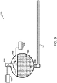
Figure 1 illustrates afire suppression system 100. Thefire suppression system 100 includes acontainer 102, afire suppressant 104, aport 106, aport 108, agas generator 110, adistribution manifold 114, arupture disc 116, and apropellant gas 118, and may include apressure gauge 120, and acontrol unit 122. - The
container 102 may take the form of a metal bottle or tank, however, any form that is suitable for containing pressurized liquids, vapors, and/or gases is possible. Thecontainer 102 contains or holds thefire suppressant 104. - The
fire suppressant 104 may take the form of Halon or any Halon replacement material that is known in the art, such as inert gases or halocarbons. Inside thecontainer 102, thefire suppressant 104 is primarily be in the liquid phase, however some of thefire suppressant 104 within thecontainer 102 may exist in the vapor phase as well. - The
gas generator 110 is configured to cause one or more solid precursors of a propellant gas 112 (shown inFigure 9 ) to react and produce thepropellant gas 112. Thegas generator 110 may take the form of a gas generator that can typically be found as part of an automobile supplemental restraint system (e.g., for deploying airbags). Thegas generator 110 is coupled to thecontainer 102 via theport 106. - The
distribution manifold 114 is coupled to thecontainer 102 via theport 108 and therupture disc 116. Thedistribution manifold 114 may include a network of pipes configured to distribute the expelledfire suppressant 104 to various areas of interest. - The
rupture disc 116 may include a membrane (e.g., a thin metal membrane) that is configured to rupture when exposed to a particular amount of pressure within thecontainer 102. As therupture disc 116 ruptures, thecontainer 102 is opened up to thedistribution manifold 114. - In some instances, the
container 102 may be filled with thepropellant gas 118, which may be the same gas as thepropellant gas 112 or a different gas than thepropellant gas 112. In many examples, thefire suppressant 104 may have a low vapor pressure. Therefore, thecontainer 102 may be charged with thepropellant gas 118 as a means for establishing a pressure for thepressure gauge 120 to monitor. In this way, thepressure gauge 120 may monitor the pressure within thecontainer 102 to detect possible leaks within the wall of thecontainer 102. - The
control unit 122 may take the form of a smoke detector or a heat detector, for example. Thecontrol unit 122 may be configured to detect the presence of conditions that indicate a possible fire. When thecontrol unit 122 detects such conditions (e.g., heat or smoke), thecontrol unit 122 may provide an input to thegas generator 110 that causes thegas generator 110 to begin generating thepropellant gas 112. - In other examples, the
control unit 122 may take the form of a user interface 122 (e.g., a control panel). For instance, a user may be alerted to the presence of a possible fire via the user's own senses and/or via an alarm provided by a smoke detector or a heat detector. Accordingly, the user may provide input to the user interface, and the user interface may responsively send an input to thegas generator 110 to cause thegas generator 110 to generate thepropellant gas 112. -
Methods Figures 2 ,3 ,4 ,5 ,6 , and7 present example methods that can be performed by thefire suppression system 100. In other examples, the methods 200-700 may be performed by any combination of one or more suitable components described herein. The methods 300-700 are methods that can be used in conjunction with themethod 200, for example. -
Figures 2-7 may include one or more operations, functions, or actions as illustrated by one or more ofblocks - In addition, for the methods 200-700, and other processes and methods disclosed herein, the flowcharts show functionality and operation of one possible implementation of present examples. In this regard, each block may represent a module, a segment, or a portion of program code, which includes one or more instructions executable by a processor for implementing specific logical functions or steps in a process. The program code may be stored on any type of computer readable medium, for example, such as a storage device including a disk or hard drive. The computer readable medium may include a non-transitory computer readable medium, for example, such as computer readable media that stores data for short periods of time like register memory, processor cache, or Random Access Memory (RAM). The computer readable medium may also include non-transitory media, such as secondary or persistent long term storage, like read-only memory (ROM), optical or magnetic disks, or compact-disc read-only memory (CD-ROM), for example. The computer readable media may also be any other volatile or nonvolatile storage system. The computer readable medium may be considered a computer readable storage medium, a tangible storage device, or other article of manufacture, for example.
- In addition, for the methods 200-700 and other processes and methods disclosed herein, each block in
Figures 2-7 may represent circuitry that is wired to perform the specific logical functions in the process. - Referring to
Figure 2 , themethod 200 is an example method for expelling a fire suppressant from a container into a distribution manifold. - At
block 202, themethod 200 includes generating a propellant gas that flows into the container via a first port of the container, thereby causing a pressure within the container to increase. In this context, the container includes the fire suppressant prior to the generation of the propellant gas. - As shown in
Figures 8-9 , for example, thegas generator 110 generates thepropellant gas 112 by initiating a chemical reaction of one or more precursors of thepropellant gas 112. Thepropellant gas 112 flows into thecontainer 102 via theport 106. As thepropellant gas 112 flows into thecontainer 102, the pressure within thecontainer 102 increasse. Thegas generator 110 may initiate generation of thepropellant gas 112 in response to receiving an input from thecontrol unit 122, as discussed below. As shown inFigure 8 , thecontainer 102 contains thefire suppressant 104 prior to the generation of thepropellant gas 112. - At
block 204, themethod 200 includes, in response to the pressure within the container exceeding a threshold pressure, expelling the fire suppressant from a second port of the container into the distribution manifold. In this context, the generated propellant gas continues to flow into the container via the first port at least until substantially all of the fire suppressant included within the container prior to the generation of the propellant gas is expelled from the container via the second port. - As shown in
Figure 10 , thepropellant gas 112 continues to flow into thecontainer 102 and the pressure within thecontainer 102 increases to exceed a predetermined threshold pressure. At or near the threshold pressure, therupture disc 116 ruptures and the pressure within thecontainer 102 begins to expel thefire suppressant 104 from thecontainer 102 via theport 108 into thedistribution manifold 114, as shown inFigure 11 . - In some examples, the threshold pressure may be a pressure within a range of 62,05 bar (900 pounds per square inch gauge (psig)) and 75,84 bar (1100 psig). More specifically, the threshold pressure may be substantially equal to 68,95 bar (1000 psig). That is, the
method 200 may further involve expelling thefire suppressant 104 in response to the pressure within thecontainer 102 exceeding a pressure within a range of 62,05 bar (900 psig) and 75,84 bar (1100 psig), or more specifically, themethod 200 may further involve expelling thefire suppressant 104 in response to the pressure within thecontainer 102 exceeding a pressure that is substantially equal to 68,95 bar (1000 psig). - As shown in
Figures 11 and12 , thepropellant gas 112 continues to flow into thecontainer 102 via theport 106 at least until substantially all of thefire suppressant 104 is expelled from thecontainer 102 via theport 108.Figure 12 shows that thepropellant gas 112 continues to flow into thecontainer 102 after thefire suppressant 104 has been fully or nearly expelled from thecontainer 102. -
Figure 3 is a block diagram of themethod 300. Atblock 206, themethod 300 includes receiving, at the gas generator, an input. Thegas generator 110 may receive the input from thecontrol unit 122, for example. Thecontrol unit 122 may include aheat detector 122, asmoke detector 122, or auser interface 122, but other examples are possible. - At
block 208, themethod 300 includes generating the propellant gas in response to receiving the input at the gas generator. For instance,Figure 8 shows thegas generator 110 beginning to generate thepropellant gas 112 in response to thegas generator 110 receiving an input from thecontrol unit 122. Thegas generator 110 may mix one or more solid precursors of thepropellant gas 112 in response to receiving the input. -
Figure 4 is a block diagram of themethod 400. Atblock 210, themethod 400 includes, after rupturing the disc, causing the pressure within the container to remain greater than or equal to the threshold pressure at least until substantially all of the fire suppressant included within the container prior to the generation of the propellant gas is expelled from the container. - As described above, the
gas generator 110 continues to produce thepropellant gas 112 and flow thepropellant gas 112 into thecontainer 102 at least until thefire suppressant 104 has been substantially expelled from thecontainer 102. The ruptureddisc 116 may perform a regulation function whereby thepropellant gas 112 flows into thecontainer 102 at a rate sufficient to maintain the pressure within thecontainer 102 at or above the threshold pressure at least until thefire suppressant 104 has been substantially expelled from thecontainer 102. -
Figure 5 is a block diagram of themethod 500. Atblock 212, themethod 500 includes monitoring, via a pressure gauge, the pressure within the container generated at least in part by the second propellant gas. In this context, a second propellant gas is included within the container prior to the generation of the propellant gas. - Referring to
Figure 1 , for example, thepropellant gas 118 may be filled into thecontainer 102 along with thefire suppressant 104 prior to sealing thecontainer 102. Thepressure gauge 120 may monitor the pressure within thecontainer 102 prior to, during, and/or after expulsion of thefire suppressant 104. The vapor pressure maintained within thecontainer 102 may correspond, at least in part, to thepropellant gas 118. -
Figure 6 is block diagram of themethod 600. Atblock 214, themethod 600 includes flowing the expelled fire suppressant through the distribution manifold in a liquid phase. Atblock 216, themethod 600 includes dispensing the expelled fire suppressant from the distribution manifold in the liquid phase. As shown inFigure 12 , the continuing generation of thepropellant gas 112 maintains a pressure within thecontainer 102 and thedistribution manifold 114 sufficient to keep thefire suppressant 104 from evaporating at least until thefire suppressant 104 reaches dispensing nozzles of thedistribution manifold 114. -
Figure 7 is a block diagram of themethod 700. Atblock 218, themethod 700 includes reducing the pressure within the container to be less than the threshold pressure after substantially all of the fire suppressant included within the container prior to the generation of the propellant gas is expelled from the container. This is discussed in more detail below with reference toFigure 13 . -
Figure 13 graphically depicts the pressure within thecontainer 102 with respect to time. At time t1 depicted byFigure 1 , the pressure remains somewhat constant at low pressure, as thegas generator 110 has not yet been activated. At time ti, the pressure within thecontainer 102 may primarily correspond to thepre-filled propellant gas 118. At time t2 depicted byFigure 8 , thegas generator 110 is activated and begins generating thepropellant gas 112, and the pressure within thecontainer 102 begins to increase. At time t3 depicted byFigure 9 , thepropellant gas 112 fills into thecontainer 102 and the pressure increases. At time t4 depicted byFigure 10 , therupture disc 116 ruptures in response to the pressure within thecontainer 102 exceeding a predetermined threshold pressure. The rupturedrupture disc 116 allows the pressure built up in thecontainer 102 to begin to expel some of thefire suppressant 104 out of theport 108. At time ts depicted byFigure 11 , thepropellant gas 112 continues to fill thecontainer 102 while thefire suppressant 104 continues to be expelled from thecontainer 102. The pressure remains somewhat constant at a high pressure during this time (e.g., near the predetermined threshold pressure). At time t6 depicted byFigure 12 , thegas generator 110 is no longer generating thepropellant gas 112, and the pressure begins to decrease as the remainder of the propellant gases and thefire suppressant 104 continue to exit thecontainer 102. - The description of the different advantageous arrangements has been presented for purposes of illustration and description, and is not intended to be exhaustive or limited to the examples in the form disclosed. Many modifications and variations will be apparent to those of ordinary skill in the art. Further, different advantageous examples may describe different advantages as compared to other advantageous examples. The example or examples selected are chosen and described in order to explain the principles of the examples, the practical application, and to enable others of ordinary skill in the art to understand the disclosure for various examples with various modifications as are suited to the particular use contemplated.
Claims (12)
- A method (200) for expelling a fire suppressant (104) in a liquid phase from a container (102) into a distribution manifold (114), the method (200) comprising:generating (202) a propellant gas (112) that flows into the container (102) via a first port (106) of the container (102), thereby causing a pressure within the container (102) to increase, wherein the container (102) includes the fire suppressant (104) in the liquid phase prior to the generation of the propellant gas (112); andin response to the pressure within the container (102) exceeding a threshold pressure (204), expelling the fire suppressant (104) from a second port (108) of the container (102) into the distribution manifold (114), wherein the generated propellant gas (112) continues to flow into the container (102) via the first port (106) at least until substantially all of the fire suppressant (104) included within the container (102) prior to the generation of the propellant gas (112) is expelled from the container (102) via the second port (108),wherein generating the propellant gas (112) comprises generating the propellant gas (112) via a gas generator (110) initiating a chemical reaction of one or more solid precursors of the propellant gas (112),wherein expelling the fire suppressant (104) from the second port (108) of the container (102) into the distribution manifold (114) comprises rupturing a rupture disc (116), that seals the second port (108), in response to the increased pressure within the container (102) exceeding the threshold pressure, andafter rupturing the rupture disc (116), causing the pressure within the container (102) to remain greater than or equal to the threshold pressure at least until substantially all of the fire suppressant (104) included within the container (102) prior to the generation of the propellant gas (112) is expelled from the container (102).
- The method (200) of claim 1, further comprising:receiving, at the gas generator (110), an input,wherein generating the propellant gas (112) comprises generating the propellant gas (112) in response to receiving the input at the gas generator (110).
- The method (200) of claim 2, wherein receiving the input comprises receiving the input from a heat detector (122), a smoke detector (122), or a user interface (122).
- The method (200) of any one of claims 1-3,
wherein prior to the generation of the propellant gas (112), a second propellant gas (118) is included within the container (102), the method (200) further comprising:
monitoring, via a pressure gauge (120), the pressure within the container (102) generated at least in part by the second propellant gas (118). - The method (200) of any one of claims 1-4, further comprising:flowing the expelled fire suppressant (104) through the distribution manifold (114) in a liquid phase; anddispensing the expelled fire suppressant (104) from the distribution manifold (114) in the liquid phase.
- The method (200) of any one of claims 1-5, further comprising reducing the pressure within the container (102) to be less than the threshold pressure after substantially all of the fire suppressant (104) included within the container (102) prior to the generation of the propellant gas (112) is expelled from the container (102).
- Afire suppression system (100) comprising:a container (102) including a fire suppressant (104) in a liquid phase, wherein the container (102) comprises a first port (106) and a second port (108);a gas generator (110) coupled to the first port (106), wherein the gas generator (110) is configured to generate and flow a propellant gas (112) into the container (102) via the first port (106), thereby causing a pressure within the container (102) to increase;one or more solid precursors of the propellant gas (112);
a distribution manifold (114) coupled to the second port (108); anda rupture disc (116) sealing the second port (108), wherein the rupture disc (116) is configured to (a) rupture in response to the increased pressure within the container (102) exceeding a threshold pressure and (b) in response to the rupture, release the fire suppressant (104) into the distribution manifold (114);wherein the gas generator (110) is configured to generate the propellant gas (112) by initiating a chemical reaction of the one or more precursors of the propellant gas (112); and
wherein the system is further configured to cause, after rupturing the rupture disc (116), the pressure within the container (102) to remain greater than or equal to the threshold pressure at least until substantially all of the fire suppressant (104) included within the container (102) prior to the generation of the propellant gas (112) is expelled from the container (102). - The fire suppression system (100) of claim 7, further comprising a control unit (122), wherein the control unit (122) is configured to (a) detect conditions indicative of a presence of a fire and (b) in response to the detected conditions, send an input to the gas generator (110) to cause the gas generator (110) to generate the propellant gas (112).
- The fire suppression system (100) of claim 8 or 9, further comprising a user interface (122) that is configured to (a) receive user input and (b) in response to receiving the user input, send a control input to the gas generator (110) to cause the gas generator (110) to generate the propellant gas (112).
- The fire suppression system (100) of any one of claims 7-9,
wherein the container (102) also includes a second propellant gas (118), the fire suppression system (100) further comprising:
a pressure gauge (120) configured to monitor the pressure within the container (102) generated at least in part by the second propellant gas (118). - The fire suppression system (100) of any one of claims 7-10, wherein at least 60% and no more than 80% of a total volume of the container (102) is filled with the fire suppressant (104).
- The fire suppression system (100) of any one of claims 7-11, wherein the disc (116) is configured to rupture in response to the pressure within the container (102) exceeding a pressure within a range of 62,05 bar to 75,84 bar.
Applications Claiming Priority (1)
| Application Number | Priority Date | Filing Date | Title |
|---|---|---|---|
| US15/258,726 US10238902B2 (en) | 2016-09-07 | 2016-09-07 | Expulsion of a fire suppressant from a container |
Publications (2)
| Publication Number | Publication Date |
|---|---|
| EP3292887A1 EP3292887A1 (en) | 2018-03-14 |
| EP3292887B1 true EP3292887B1 (en) | 2021-07-07 |
Family
ID=59523000
Family Applications (1)
| Application Number | Title | Priority Date | Filing Date |
|---|---|---|---|
| EP17184714.8A Active EP3292887B1 (en) | 2016-09-07 | 2017-08-03 | Expulsion of a fire suppressant from a container |
Country Status (6)
| Country | Link |
|---|---|
| US (1) | US10238902B2 (en) |
| EP (1) | EP3292887B1 (en) |
| JP (1) | JP7050438B2 (en) |
| CN (1) | CN107789776A (en) |
| CA (1) | CA2975134C (en) |
| GB (1) | GB2556369B (en) |
Families Citing this family (1)
| Publication number | Priority date | Publication date | Assignee | Title |
|---|---|---|---|---|
| WO2023218382A1 (en) * | 2022-05-12 | 2023-11-16 | Tyco Fire Products Lp | Dual-function suppression system for mobile vehicles |
Citations (1)
| Publication number | Priority date | Publication date | Assignee | Title |
|---|---|---|---|---|
| US20070158085A1 (en) * | 2005-11-04 | 2007-07-12 | Siemens S.A.S. | Fire extinguishing apparatus and method with gas generator and extinguishing agent |
Family Cites Families (45)
| Publication number | Priority date | Publication date | Assignee | Title |
|---|---|---|---|---|
| US2605848A (en) * | 1950-04-28 | 1952-08-05 | Carnoy Products Corp | Dry chemical fire extinguisher |
| US2804929A (en) * | 1955-11-07 | 1957-09-03 | Rohr Aircraft Corp | Fluid container and discharge control valve |
| US3012613A (en) * | 1959-06-24 | 1961-12-12 | Specialties Dev Corp | Fire preventing system |
| US3139934A (en) * | 1961-06-26 | 1964-07-07 | Du Pont | Fire extinguishing apparatus |
| US3773111A (en) * | 1971-04-05 | 1973-11-20 | B Dunn | Fire extinguishing apparatus |
| JPS576276Y2 (en) * | 1978-12-28 | 1982-02-05 | ||
| US4319640A (en) * | 1979-12-06 | 1982-03-16 | The United States Of America As Represented By The Secretary Of The Army | Gas generator-actuated fire suppressant mechanism |
| US4889189A (en) * | 1983-10-28 | 1989-12-26 | Rozniecki Edward J | Fire suppressant mechanism and method for sizing same |
| JP2703431B2 (en) * | 1991-09-26 | 1998-01-26 | 日本碍子株式会社 | Fire extinguisher in sodium-sulfur battery |
| US5423384A (en) * | 1993-06-24 | 1995-06-13 | Olin Corporation | Apparatus for suppressing a fire |
| US5449041A (en) * | 1993-06-24 | 1995-09-12 | Olin Corporation | Apparatus and method for suppressing a fire |
| US5393437A (en) | 1994-05-31 | 1995-02-28 | Chemguard, Inc. | Fire extinguishing material |
| JP3027058U (en) * | 1995-12-07 | 1996-07-30 | 建藏 吉田 | Nitrogen gas cylinder type pressurized water supply device |
| US5992528A (en) * | 1997-04-17 | 1999-11-30 | Autoliv Asp, Inc. | Inflator based fire suppression system |
| US5884710A (en) * | 1997-07-07 | 1999-03-23 | Autoliv Asp, Inc. | Liquid pyrotechnic fire extinguishing composition producing a large amount of water vapor |
| US6095251A (en) * | 1997-07-22 | 2000-08-01 | Primex Technologies, Inc. | Dual stage fire extinguisher |
| US6024889A (en) * | 1998-01-29 | 2000-02-15 | Primex Technologies, Inc. | Chemically active fire suppression composition |
| US6076468A (en) * | 1998-03-26 | 2000-06-20 | Atlantic Research Corporation | Solid propellant/water type hybrid gas generator |
| US6116348A (en) * | 1998-07-17 | 2000-09-12 | R-Amtech International, Inc. | Method and apparatus for fire extinguishing |
| US6257341B1 (en) * | 1998-09-22 | 2001-07-10 | Joseph Michael Bennett | Compact affordable inert gas fire extinguishing system |
| US6016874A (en) | 1998-09-22 | 2000-01-25 | Bennett; Joseph Michael | Compact affordable inert gas fire extinguishing system |
| WO2000048683A1 (en) * | 1999-02-19 | 2000-08-24 | Primex Aerospace Company | Fire suppression composition and device |
| ES2283909T3 (en) * | 1999-03-31 | 2007-11-01 | Aerojet-General Corporation | HYBRID EXTINGUISHER. |
| US6164383A (en) * | 1999-08-17 | 2000-12-26 | Thomas; Orrett H. | Fire extinguishing system for automotive vehicles |
| US6513602B1 (en) * | 2000-09-13 | 2003-02-04 | Universal Propolsion Company | Gas generating device |
| US6612243B1 (en) * | 2001-02-27 | 2003-09-02 | Aerojet - General Corporation | Fire extinguisher |
| SE0200425L (en) * | 2002-02-14 | 2003-04-15 | Dafo Brand Ab | Extinguishing media and systems with containers |
| EP1613400A4 (en) * | 2003-04-15 | 2008-05-14 | Aerojet General Co | Vehicle fire extinguisher |
| US20040216903A1 (en) * | 2003-04-15 | 2004-11-04 | Wierenga Paul H. | Hermetically sealed gas propellant cartridge for fire extinguishers |
| EP1484088B1 (en) * | 2003-06-04 | 2009-12-23 | E.S.P. S.r.l. | A portable aerosol fire-extinguisher |
| FR2864905B1 (en) * | 2004-01-09 | 2006-07-14 | Airbus France | FIRE EXTINGUISHING DEVICE |
| FR2870459B1 (en) * | 2004-05-19 | 2006-08-25 | Airbus France Sas | DEVICE FOR EXTINGUISHING FIRE BY INJECTION OF A GAS GENERATED BY THE COMBUSTION OF A PYROTECHNIC BLOCK |
| FR2879107B1 (en) * | 2004-12-09 | 2007-04-06 | Airbus France Sas | DEVICE FOR INCREASING THE EFFICIENCY OF PRESSURIZING GAS IN A BOTTLE OF EXTINGUISHER |
| WO2006138733A2 (en) * | 2005-06-17 | 2006-12-28 | Aerojet-General Corporation | Hybrid fire extinguisher for extended suppression times |
| US7614458B2 (en) * | 2006-04-10 | 2009-11-10 | Fireaway Llc | Ignition unit for aerosol fire-retarding delivery device |
| WO2007130498A2 (en) * | 2006-05-04 | 2007-11-15 | Fireaway Llc | Portable fire extinguishing apparatus and method |
| EP1902757B1 (en) * | 2006-09-21 | 2010-04-21 | Siemens S.A.S. | Propulsion device for an agent contained in a cavity |
| CA2703853C (en) * | 2007-10-30 | 2015-11-24 | Airbus Operations | Fluid ejection device with enhanced leaktightness |
| US8439072B2 (en) * | 2010-10-22 | 2013-05-14 | International Business Machines Corporation | Hydrocarbon gas delivery system |
| GB2486185A (en) | 2010-12-03 | 2012-06-13 | Niall Campbell Hastie | Pressurised Fire and Smoke Suppression System |
| US8973670B2 (en) | 2010-12-30 | 2015-03-10 | William Armand Enk, SR. | Fire suppression system |
| FR2972360B1 (en) * | 2011-03-10 | 2013-04-05 | Pyroalliance | FIRE EXTINGUISHING DEVICE OFFSET |
| MY172624A (en) * | 2011-08-25 | 2019-12-06 | Pyrogen Mfg Sdn Bhd | Fire extinguishing system |
| US9192798B2 (en) * | 2011-10-25 | 2015-11-24 | Kidde Technologies, Inc. | Automatic fire extinguishing system with gaseous and dry powder fire suppression agents |
| FR2992575B1 (en) * | 2012-06-29 | 2015-07-17 | Herakles | DEVICE FOR SPRAYING A LIQUID |
-
2016
- 2016-09-07 US US15/258,726 patent/US10238902B2/en active Active
-
2017
- 2017-08-01 CA CA2975134A patent/CA2975134C/en active Active
- 2017-08-03 EP EP17184714.8A patent/EP3292887B1/en active Active
- 2017-08-17 JP JP2017157505A patent/JP7050438B2/en active Active
- 2017-08-22 GB GB1713446.1A patent/GB2556369B/en active Active
- 2017-08-23 CN CN201710727077.2A patent/CN107789776A/en active Pending
Patent Citations (1)
| Publication number | Priority date | Publication date | Assignee | Title |
|---|---|---|---|---|
| US20070158085A1 (en) * | 2005-11-04 | 2007-07-12 | Siemens S.A.S. | Fire extinguishing apparatus and method with gas generator and extinguishing agent |
Also Published As
| Publication number | Publication date |
|---|---|
| CA2975134C (en) | 2021-08-24 |
| JP2018089349A (en) | 2018-06-14 |
| CA2975134A1 (en) | 2018-03-07 |
| JP7050438B2 (en) | 2022-04-08 |
| GB2556369B (en) | 2020-02-19 |
| GB201713446D0 (en) | 2017-10-04 |
| CN107789776A (en) | 2018-03-13 |
| US10238902B2 (en) | 2019-03-26 |
| US20180064975A1 (en) | 2018-03-08 |
| GB2556369A (en) | 2018-05-30 |
| EP3292887A1 (en) | 2018-03-14 |
Similar Documents
| Publication | Publication Date | Title |
|---|---|---|
| CA2792793C (en) | Automatic fire extinguishing system with gaseous and dry powder fire supression agents | |
| US20040216903A1 (en) | Hermetically sealed gas propellant cartridge for fire extinguishers | |
| CA2792656C (en) | N2/co2 fire extinguishing system propellant gas mixture | |
| AU2012244106B2 (en) | Automatic fire extinguishing system with internal dip tube | |
| JP2005185835A (en) | Fire extinguishing apparatus and method, especially fire extinguishing apparatus and method for cargo room of airplane | |
| EP2938959B1 (en) | Fog-generating device comprising a reagent and ignition means | |
| US20180221695A1 (en) | Silent fire suppression system | |
| EP2586501B1 (en) | An automatic fire extinguishing system having outlet dimensions sized relative to propellant gas pressure | |
| EP3292887B1 (en) | Expulsion of a fire suppressant from a container | |
| JP6813878B2 (en) | Fire extinguishing equipment and fire extinguishing method | |
| HU193261B (en) | Method and extinguisher for fire-fighting |
Legal Events
| Date | Code | Title | Description |
|---|---|---|---|
| PUAI | Public reference made under article 153(3) epc to a published international application that has entered the european phase |
Free format text: ORIGINAL CODE: 0009012 |
|
| STAA | Information on the status of an ep patent application or granted ep patent |
Free format text: STATUS: REQUEST FOR EXAMINATION WAS MADE |
|
| 17P | Request for examination filed |
Effective date: 20170803 |
|
| AK | Designated contracting states |
Kind code of ref document: A1 Designated state(s): AL AT BE BG CH CY CZ DE DK EE ES FI FR GB GR HR HU IE IS IT LI LT LU LV MC MK MT NL NO PL PT RO RS SE SI SK SM TR |
|
| AX | Request for extension of the european patent |
Extension state: BA ME |
|
| STAA | Information on the status of an ep patent application or granted ep patent |
Free format text: STATUS: EXAMINATION IS IN PROGRESS |
|
| 17Q | First examination report despatched |
Effective date: 20190110 |
|
| GRAP | Despatch of communication of intention to grant a patent |
Free format text: ORIGINAL CODE: EPIDOSNIGR1 |
|
| STAA | Information on the status of an ep patent application or granted ep patent |
Free format text: STATUS: GRANT OF PATENT IS INTENDED |
|
| INTG | Intention to grant announced |
Effective date: 20210128 |
|
| GRAS | Grant fee paid |
Free format text: ORIGINAL CODE: EPIDOSNIGR3 |
|
| GRAA | (expected) grant |
Free format text: ORIGINAL CODE: 0009210 |
|
| STAA | Information on the status of an ep patent application or granted ep patent |
Free format text: STATUS: THE PATENT HAS BEEN GRANTED |
|
| AK | Designated contracting states |
Kind code of ref document: B1 Designated state(s): AL AT BE BG CH CY CZ DE DK EE ES FI FR GB GR HR HU IE IS IT LI LT LU LV MC MK MT NL NO PL PT RO RS SE SI SK SM TR |
|
| REG | Reference to a national code |
Ref country code: GB Ref legal event code: FG4D |
|
| REG | Reference to a national code |
Ref country code: AT Ref legal event code: REF Ref document number: 1407979 Country of ref document: AT Kind code of ref document: T Effective date: 20210715 |
|
| REG | Reference to a national code |
Ref country code: DE Ref legal event code: R096 Ref document number: 602017041536 Country of ref document: DE |
|
| REG | Reference to a national code |
Ref country code: IE Ref legal event code: FG4D |
|
| REG | Reference to a national code |
Ref country code: LT Ref legal event code: MG9D |
|
| REG | Reference to a national code |
Ref country code: NL Ref legal event code: MP Effective date: 20210707 |
|
| REG | Reference to a national code |
Ref country code: AT Ref legal event code: MK05 Ref document number: 1407979 Country of ref document: AT Kind code of ref document: T Effective date: 20210707 |
|
| PG25 | Lapsed in a contracting state [announced via postgrant information from national office to epo] |
Ref country code: PT Free format text: LAPSE BECAUSE OF FAILURE TO SUBMIT A TRANSLATION OF THE DESCRIPTION OR TO PAY THE FEE WITHIN THE PRESCRIBED TIME-LIMIT Effective date: 20211108 Ref country code: NO Free format text: LAPSE BECAUSE OF FAILURE TO SUBMIT A TRANSLATION OF THE DESCRIPTION OR TO PAY THE FEE WITHIN THE PRESCRIBED TIME-LIMIT Effective date: 20211007 Ref country code: NL Free format text: LAPSE BECAUSE OF FAILURE TO SUBMIT A TRANSLATION OF THE DESCRIPTION OR TO PAY THE FEE WITHIN THE PRESCRIBED TIME-LIMIT Effective date: 20210707 Ref country code: ES Free format text: LAPSE BECAUSE OF FAILURE TO SUBMIT A TRANSLATION OF THE DESCRIPTION OR TO PAY THE FEE WITHIN THE PRESCRIBED TIME-LIMIT Effective date: 20210707 Ref country code: FI Free format text: LAPSE BECAUSE OF FAILURE TO SUBMIT A TRANSLATION OF THE DESCRIPTION OR TO PAY THE FEE WITHIN THE PRESCRIBED TIME-LIMIT Effective date: 20210707 Ref country code: HR Free format text: LAPSE BECAUSE OF FAILURE TO SUBMIT A TRANSLATION OF THE DESCRIPTION OR TO PAY THE FEE WITHIN THE PRESCRIBED TIME-LIMIT Effective date: 20210707 Ref country code: BG Free format text: LAPSE BECAUSE OF FAILURE TO SUBMIT A TRANSLATION OF THE DESCRIPTION OR TO PAY THE FEE WITHIN THE PRESCRIBED TIME-LIMIT Effective date: 20211007 Ref country code: AT Free format text: LAPSE BECAUSE OF FAILURE TO SUBMIT A TRANSLATION OF THE DESCRIPTION OR TO PAY THE FEE WITHIN THE PRESCRIBED TIME-LIMIT Effective date: 20210707 Ref country code: LT Free format text: LAPSE BECAUSE OF FAILURE TO SUBMIT A TRANSLATION OF THE DESCRIPTION OR TO PAY THE FEE WITHIN THE PRESCRIBED TIME-LIMIT Effective date: 20210707 Ref country code: RS Free format text: LAPSE BECAUSE OF FAILURE TO SUBMIT A TRANSLATION OF THE DESCRIPTION OR TO PAY THE FEE WITHIN THE PRESCRIBED TIME-LIMIT Effective date: 20210707 Ref country code: SE Free format text: LAPSE BECAUSE OF FAILURE TO SUBMIT A TRANSLATION OF THE DESCRIPTION OR TO PAY THE FEE WITHIN THE PRESCRIBED TIME-LIMIT Effective date: 20210707 |
|
| PG25 | Lapsed in a contracting state [announced via postgrant information from national office to epo] |
Ref country code: PL Free format text: LAPSE BECAUSE OF FAILURE TO SUBMIT A TRANSLATION OF THE DESCRIPTION OR TO PAY THE FEE WITHIN THE PRESCRIBED TIME-LIMIT Effective date: 20210707 Ref country code: LV Free format text: LAPSE BECAUSE OF FAILURE TO SUBMIT A TRANSLATION OF THE DESCRIPTION OR TO PAY THE FEE WITHIN THE PRESCRIBED TIME-LIMIT Effective date: 20210707 Ref country code: GR Free format text: LAPSE BECAUSE OF FAILURE TO SUBMIT A TRANSLATION OF THE DESCRIPTION OR TO PAY THE FEE WITHIN THE PRESCRIBED TIME-LIMIT Effective date: 20211008 |
|
| REG | Reference to a national code |
Ref country code: CH Ref legal event code: PL |
|
| REG | Reference to a national code |
Ref country code: DE Ref legal event code: R097 Ref document number: 602017041536 Country of ref document: DE |
|
| REG | Reference to a national code |
Ref country code: BE Ref legal event code: MM Effective date: 20210831 |
|
| PG25 | Lapsed in a contracting state [announced via postgrant information from national office to epo] |
Ref country code: LI Free format text: LAPSE BECAUSE OF NON-PAYMENT OF DUE FEES Effective date: 20210831 Ref country code: DK Free format text: LAPSE BECAUSE OF FAILURE TO SUBMIT A TRANSLATION OF THE DESCRIPTION OR TO PAY THE FEE WITHIN THE PRESCRIBED TIME-LIMIT Effective date: 20210707 Ref country code: CH Free format text: LAPSE BECAUSE OF NON-PAYMENT OF DUE FEES Effective date: 20210831 |
|
| PLBE | No opposition filed within time limit |
Free format text: ORIGINAL CODE: 0009261 |
|
| STAA | Information on the status of an ep patent application or granted ep patent |
Free format text: STATUS: NO OPPOSITION FILED WITHIN TIME LIMIT |
|
| PG25 | Lapsed in a contracting state [announced via postgrant information from national office to epo] |
Ref country code: SM Free format text: LAPSE BECAUSE OF FAILURE TO SUBMIT A TRANSLATION OF THE DESCRIPTION OR TO PAY THE FEE WITHIN THE PRESCRIBED TIME-LIMIT Effective date: 20210707 Ref country code: SK Free format text: LAPSE BECAUSE OF FAILURE TO SUBMIT A TRANSLATION OF THE DESCRIPTION OR TO PAY THE FEE WITHIN THE PRESCRIBED TIME-LIMIT Effective date: 20210707 Ref country code: RO Free format text: LAPSE BECAUSE OF FAILURE TO SUBMIT A TRANSLATION OF THE DESCRIPTION OR TO PAY THE FEE WITHIN THE PRESCRIBED TIME-LIMIT Effective date: 20210707 Ref country code: MC Free format text: LAPSE BECAUSE OF FAILURE TO SUBMIT A TRANSLATION OF THE DESCRIPTION OR TO PAY THE FEE WITHIN THE PRESCRIBED TIME-LIMIT Effective date: 20210707 Ref country code: LU Free format text: LAPSE BECAUSE OF NON-PAYMENT OF DUE FEES Effective date: 20210803 Ref country code: EE Free format text: LAPSE BECAUSE OF FAILURE TO SUBMIT A TRANSLATION OF THE DESCRIPTION OR TO PAY THE FEE WITHIN THE PRESCRIBED TIME-LIMIT Effective date: 20210707 Ref country code: CZ Free format text: LAPSE BECAUSE OF FAILURE TO SUBMIT A TRANSLATION OF THE DESCRIPTION OR TO PAY THE FEE WITHIN THE PRESCRIBED TIME-LIMIT Effective date: 20210707 Ref country code: AL Free format text: LAPSE BECAUSE OF FAILURE TO SUBMIT A TRANSLATION OF THE DESCRIPTION OR TO PAY THE FEE WITHIN THE PRESCRIBED TIME-LIMIT Effective date: 20210707 |
|
| 26N | No opposition filed |
Effective date: 20220408 |
|
| GBPC | Gb: european patent ceased through non-payment of renewal fee |
Effective date: 20211007 |
|
| PG25 | Lapsed in a contracting state [announced via postgrant information from national office to epo] |
Ref country code: IT Free format text: LAPSE BECAUSE OF FAILURE TO SUBMIT A TRANSLATION OF THE DESCRIPTION OR TO PAY THE FEE WITHIN THE PRESCRIBED TIME-LIMIT Effective date: 20210707 Ref country code: IE Free format text: LAPSE BECAUSE OF NON-PAYMENT OF DUE FEES Effective date: 20210803 Ref country code: GB Free format text: LAPSE BECAUSE OF NON-PAYMENT OF DUE FEES Effective date: 20211007 Ref country code: BE Free format text: LAPSE BECAUSE OF NON-PAYMENT OF DUE FEES Effective date: 20210831 |
|
| PG25 | Lapsed in a contracting state [announced via postgrant information from national office to epo] |
Ref country code: HU Free format text: LAPSE BECAUSE OF FAILURE TO SUBMIT A TRANSLATION OF THE DESCRIPTION OR TO PAY THE FEE WITHIN THE PRESCRIBED TIME-LIMIT; INVALID AB INITIO Effective date: 20170803 |
|
| P01 | Opt-out of the competence of the unified patent court (upc) registered |
Effective date: 20230503 |
|
| PG25 | Lapsed in a contracting state [announced via postgrant information from national office to epo] |
Ref country code: CY Free format text: LAPSE BECAUSE OF FAILURE TO SUBMIT A TRANSLATION OF THE DESCRIPTION OR TO PAY THE FEE WITHIN THE PRESCRIBED TIME-LIMIT Effective date: 20210707 |
|
| PGFP | Annual fee paid to national office [announced via postgrant information from national office to epo] |
Ref country code: FR Payment date: 20230825 Year of fee payment: 7 Ref country code: DE Payment date: 20230829 Year of fee payment: 7 |