EP3292772B1 - Inhalateur d'arôme sans combustion - Google Patents
Inhalateur d'arôme sans combustion Download PDFInfo
- Publication number
- EP3292772B1 EP3292772B1 EP15894111.2A EP15894111A EP3292772B1 EP 3292772 B1 EP3292772 B1 EP 3292772B1 EP 15894111 A EP15894111 A EP 15894111A EP 3292772 B1 EP3292772 B1 EP 3292772B1
- Authority
- EP
- European Patent Office
- Prior art keywords
- liquid surface
- surface forming
- forming location
- atomizer
- flavor inhaler
- Prior art date
- Legal status (The legal status is an assumption and is not a legal conclusion. Google has not performed a legal analysis and makes no representation as to the accuracy of the status listed.)
- Active
Links
Images

Classifications
-
- A—HUMAN NECESSITIES
- A24—TOBACCO; CIGARS; CIGARETTES; SIMULATED SMOKING DEVICES; SMOKERS' REQUISITES
- A24F—SMOKERS' REQUISITES; MATCH BOXES; SIMULATED SMOKING DEVICES
- A24F40/00—Electrically operated smoking devices; Component parts thereof; Manufacture thereof; Maintenance or testing thereof; Charging means specially adapted therefor
- A24F40/40—Constructional details, e.g. connection of cartridges and battery parts
- A24F40/46—Shape or structure of electric heating means
-
- A—HUMAN NECESSITIES
- A24—TOBACCO; CIGARS; CIGARETTES; SIMULATED SMOKING DEVICES; SMOKERS' REQUISITES
- A24F—SMOKERS' REQUISITES; MATCH BOXES; SIMULATED SMOKING DEVICES
- A24F40/00—Electrically operated smoking devices; Component parts thereof; Manufacture thereof; Maintenance or testing thereof; Charging means specially adapted therefor
- A24F40/05—Devices without heating means
-
- A—HUMAN NECESSITIES
- A61—MEDICAL OR VETERINARY SCIENCE; HYGIENE
- A61M—DEVICES FOR INTRODUCING MEDIA INTO, OR ONTO, THE BODY; DEVICES FOR TRANSDUCING BODY MEDIA OR FOR TAKING MEDIA FROM THE BODY; DEVICES FOR PRODUCING OR ENDING SLEEP OR STUPOR
- A61M11/00—Sprayers or atomisers specially adapted for therapeutic purposes
- A61M11/001—Particle size control
-
- A—HUMAN NECESSITIES
- A61—MEDICAL OR VETERINARY SCIENCE; HYGIENE
- A61M—DEVICES FOR INTRODUCING MEDIA INTO, OR ONTO, THE BODY; DEVICES FOR TRANSDUCING BODY MEDIA OR FOR TAKING MEDIA FROM THE BODY; DEVICES FOR PRODUCING OR ENDING SLEEP OR STUPOR
- A61M11/00—Sprayers or atomisers specially adapted for therapeutic purposes
- A61M11/04—Sprayers or atomisers specially adapted for therapeutic purposes operated by the vapour pressure of the liquid to be sprayed or atomised
- A61M11/041—Sprayers or atomisers specially adapted for therapeutic purposes operated by the vapour pressure of the liquid to be sprayed or atomised using heaters
- A61M11/042—Sprayers or atomisers specially adapted for therapeutic purposes operated by the vapour pressure of the liquid to be sprayed or atomised using heaters electrical
-
- A—HUMAN NECESSITIES
- A61—MEDICAL OR VETERINARY SCIENCE; HYGIENE
- A61M—DEVICES FOR INTRODUCING MEDIA INTO, OR ONTO, THE BODY; DEVICES FOR TRANSDUCING BODY MEDIA OR FOR TAKING MEDIA FROM THE BODY; DEVICES FOR PRODUCING OR ENDING SLEEP OR STUPOR
- A61M15/00—Inhalators
- A61M15/06—Inhaling appliances shaped like cigars, cigarettes or pipes
-
- A—HUMAN NECESSITIES
- A24—TOBACCO; CIGARS; CIGARETTES; SIMULATED SMOKING DEVICES; SMOKERS' REQUISITES
- A24F—SMOKERS' REQUISITES; MATCH BOXES; SIMULATED SMOKING DEVICES
- A24F40/00—Electrically operated smoking devices; Component parts thereof; Manufacture thereof; Maintenance or testing thereof; Charging means specially adapted therefor
- A24F40/10—Devices using liquid inhalable precursors
Definitions
- the present invention relates to a non-combustion type flavor inhaler having an atomizer that atomizes an aerosol source without burning.
- the non-combustion type flavor inhaler has a reservoir that stores an aerosol source, a capillary tube that sucks up the aerosol source from upstream toward downstream, and an atomizer that atomizes the aerosol source sucked up by the capillary tube.
- An upstream end of the capillary tube reaches the aerosol source stored in the reservoir, and the atomizer is disposed at a downstream end of the capillary tube (e.g., Patent Literatures 1 and 2).
- a first feature is summarized as a non-combustion type flavor inhaler comprising: a reservoir storing an aerosol source; a transfer unit transferring the aerosol source from upstream of the liquid surface forming location to a liquid surface forming location at which a liquid surface of the aerosol source is formed, the transfer unit being configured to form the liquid surface; a suction port arranged downstream of the liquid surface forming location; a first atomizer atomizing the aerosol source located upstream of the liquid surface forming location; and a second atomizer atomizing a droplet generated from the liquid surface formed at the liquid surface forming location, the droplet being located downstream of the liquid surface forming location.
- a second feature is summarized as the non-combustion type flavor inhaler according to the first feature, wherein the transfer unit is configured by a columnar member extending from upstream toward downstream, the columnar member holding the aerosol source such that the liquid surface is formed at the liquid surface forming location.
- a third feature is summarized as the non-combustion type flavor inhaler according to the first feature or the second feature, wherein the first atomizer is arranged around the transfer unit at the liquid surface forming location, and the second atomizer is arranged downstream of the liquid surface forming location.
- a fourth feature is summarized as the non-combustion type flavor inhaler according to any one of the first feature to the third feature, wherein the transfer unit transfers the aerosol source by a capillary phenomenon.
- a fifth feature is summarized as the non-combustion type flavor inhaler according to any one of the first feature to the fourth feature, wherein the transfer unit is formed by a tubular member transferring the aerosol source by a capillary phenomenon.
- a sixth feature is summarized as the non-combustion type flavor inhaler according to the fifth feature, wherein the tubular member has a liquid surface defining part to define the liquid surface at the liquid surface forming location, the tubular member transferring the aerosol source to at least the liquid surface forming location, the tubular member including a portion extending downstream of the liquid surface forming location.
- a seventh feature is summarized as the non-combustion type flavor inhaler according to the sixth feature, wherein the liquid surface defining part is configured by an opening disposed at the liquid surface forming location.
- an inner wall of the tubular member includes a step so that a hollow cross-sectional area on a downstream side of the liquid surface forming location is larger than a hollow cross-sectional area on the upstream side of the liquid surface forming location in an orthogonal cross section orthogonal to a direction from upstream toward downstream, and the liquid surface defining part is configured by the step.
- a ninth feature is summarized as the non-combustion type flavor inhaler according to the eighth feature, wherein the tubular member comprises: a first pipe extending upstream from the liquid surface forming location; and a second pipe extending downstream at least from the liquid surface forming location, the second pipe is arranged outside the first pipe in the orthogonal cross section, and the step is formed by an inner wall of the first pipe, a downstream end of the first pipe, and an inner wall of the second pipe.
- a tenth feature is summarized as the non-combustion type flavor inhaler according to the sixth feature, wherein a property of an inner wall of the tubular member is configured to change at the liquid surface forming location or on an upstream side of the liquid surface forming location.
- An eleventh feature is summarized as the non-combustion type flavor inhaler according to any one of the sixth feature to the tenth feature, wherein the second atomizer is arranged around the tubular member on a downstream side of the liquid surface forming location.
- a twelfth feature is summarized as the non-combustion type flavor inhaler according to any one of the first feature to the eleventh feature, wherein the first atomizer and the second atomizer are provided continuously over the liquid surface forming location.
- the aerosol source sucked up by the capillary tube reaches the downstream end of the capillary tube due to a capillary phenomenon. Therefore, a droplet with a large particle diameter may be scattered due to atomization of the aerosol source reaching the downstream end of the capillary tube.
- a non-combustion type flavor inhaler comprises: a reservoir storing an aerosol source; a transfer unit transferring the aerosol source from upstream of the liquid surface forming location to a liquid surface forming location at which a liquid surface of the aerosol source is formed, the transfer unit being configured to form the liquid surface; a suction port arranged downstream of the liquid surface forming location; a first atomizer atomizing the aerosol source located upstream of the liquid surface forming location; and a second atomizer atomizing a droplet generated from the liquid surface formed at the liquid surface forming location, the droplet being located downstream of the liquid surface forming location.
- the non-combustion type flavor inhaler includes the second atomizer that atomizes a droplet located downstream of the liquid surface forming location at which the liquid surface of the aerosol source is formed. This can suppress scattering of a droplet with a large particle diameter due to atomization of the aerosol source.
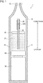
- Fig. 1 is a view showing a non-combustion type flavor inhaler 1 according to the embodiment.
- the non-combustion type flavor inhaler 1 is a device for inhaling a flavoring component without burning. It should be noted that, in the following description, the non-combustion type flavor inhaler 1 is simply referred to as a flavor inhaler 1.
- the flavor inhaler 1 includes a housing 10, a storage container 20, a tubular member 30, an atomizer 40, a power source 50, and a control circuit 60.
- the housing 10 accommodates each member forming the flavor inhaler 1.
- the housing 10 has an inlet 11 and a suction port 12.
- the inlet 11 is an opening to guide air into the housing 10.
- the suction port 12 is a portion to be held by a user's mouth, and is an opening to guide air into the user's mouth.
- the storage container 20 stores the aerosol source 21.
- the aerosol source 21 is made of a raw material that generates aerosol by atomization.
- the aerosol source 21 is liquid made of an alcohol such as glycerin or propylene glycol, water, or their mixtures.
- the aerosol source 21 preferably contains a flavoring component.
- the flavoring component may be an extracted component extracted from various types of natural materials.
- the extracted component may be a tobacco extract component, or may be a tobacco smoke condensate component.
- the flavoring component may be a component such as menthol or caffeine.
- the tubular member 30 is an example of a transfer unit that transfers the aerosol source 21 to the liquid surface forming location at which a liquid surface 21A of the aerosol source 21 is formed, from upstream of the liquid surface forming location, to form the liquid surface 21A. Further, the tubular member 30 is an example of a columnar member that extends from upstream toward downstream, and holds the aerosol source 21 such that the liquid surface 21A is formed at the liquid surface forming location.
- the tubular member 30 transfers the aerosol source 21 by a capillary phenomenon, and holds the aerosol source 21 such that the liquid surface 21A of the aerosol source 21 is formed at the liquid surface forming location. Details of the tubular member 30 around the liquid surface forming location will be described later (see Fig. 2 ).
- downstream and upstream mean downstream and upstream in a transfer of fluid.
- the fluid means the aerosol source 21, or the aerosol atomized by the atomizer 40.
- the transfer means transferring of the aerosol source 21 by a capillary phenomenon, or transferring of the aerosol source 21 or of the aerosol atomized by the atomizer 40, due to an inhalation action.
- the atomizer 40 atomizes the aerosol source 21 held by the tubular member 30, near the liquid surface 21A of the aerosol source 21.
- the atomizer 40 is formed by a coil-shaped heater wound around the tubular member 30. Details of the atomizer 40 around the liquid surface forming location will be described later (see Fig. 2 ).
- the power source 50 is a battery that accumulates electric power to be consumed by the flavor inhaler 1.
- the power source 50 is a lithium-ion battery, for example.
- the control circuit 60 controls the flavor inhaler 1.
- the control circuit 60 is configured by, for example, a CPU and a memory.
- the control circuit 60 is connected to an inhalation operation interface (such as an inhalation button) that can be operated by a user.
- an inhalation operation interface such as an inhalation button
- the control circuit 60 supplies a power output to the atomizer 40.
- the control circuit 60 stops the supply of the power output to the atomizer 40 in a time duration in which the inhalation operation interface is not being operated by the user.
- control circuit 60 is connected to a suction sensor that detects an inhalation action, and supplies the power output to the atomizer 40 in a time duration in which an inhalation action is being performed. On the other hand, the control circuit 60 stops the supply of the power output to the atomizer 40 in a time duration in which an inhalation action is not being performed.
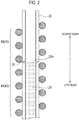
- FIG. 2 is a view showing a configuration around the liquid surface forming location according to the embodiment.
- the tubular member 30 has an opening 31 disposed at the liquid surface forming location, and has a portion extending downstream from the liquid surface forming location.
- the opening 31 constitutes a liquid surface defining part that defines the liquid surface 21A.
- an upstream portion from the opening 31 has a function of transferring the aerosol source 21 to the liquid surface forming location by a capillary phenomenon.
- a downstream portion from the opening 31 has a function of guiding a droplet scattered due to atomization, to a position where the droplet can be heated by a second atomizer 42.
- a plurality of openings 31 may be intermittently provided along a circumferential direction of the tubular member 30.
- a single opening 31 may be continuously provided over the entire circumference of the tubular member 30. That is, the tubular member 30 may be separated into two tubular members near the liquid surface forming location.
- the atomizer 40 includes a first atomizer 41 that atomizes the aerosol source 21 located upstream of the liquid surface forming location, and the second atomizer 42 that atomizes a droplet generated from the liquid surface formed at the liquid surface forming location and located downstream of the liquid surface forming location.
- the first atomizer 41 is arranged around the tubular member 30 at the liquid surface forming location
- the second atomizer 42 is arranged around the tubular member 30, on the downstream side of the liquid surface forming location.
- the first atomizer 41 and the second atomizer 42 are preferably provided continuously over the liquid surface forming location.
- the flavor inhaler 1 includes the second atomizer 42 that atomizes a droplet located downstream of the liquid surface forming location at which the liquid surface 21A of the aerosol source 21 is formed. This can suppress scattering of a droplet with a large particle diameter due to atomization of the aerosol source 21.
- the tubular member 30 extends downstream of the liquid surface forming location, and has the opening 31 disposed at the liquid surface forming location.
- the opening 31 constitutes a liquid surface defining part that defines the liquid surface 21A.
- the second atomizer 42 is arranged around the tubular member 30, on the downstream side of the liquid surface forming location. Therefore, the second atomizer 42 can be easily disposed at a position where it is easy to atomize a droplet located downstream of the liquid surface forming location.
- the first atomizer 41 and the second atomizer 42 are continuously provided over the liquid surface forming location. Therefore, it is easy to arrange and configure the atomizer 40 configured by the first atomizer 41 and the second atomizer 42.
- the liquid surface defining part that defines the liquid surface 21A is constituted by the opening 31 disposed at the liquid surface forming location.
- a liquid surface defining part that defines a liquid surface 21A is constituted by a step provided on an inner wall of a tubular member 30.
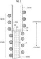
- FIG. 3 is a view showing a configuration around the liquid surface forming location according to Modified Example 1.
- the tubular member 30 includes a first pipe 32 extending upstream from the liquid surface forming location, and a second pipe 33 extending downstream at least from the liquid surface forming location.
- the second pipe 33 is arranged outside the first pipe 32 in an orthogonal cross section orthogonal to a direction from upstream toward downstream.
- the second pipe 33 may extend from upstream toward downstream of the liquid surface forming location.
- the first pipe 32 and the second pipe 33 may overlap each other at the liquid surface forming location.
- a liquid surface defining part that defines the liquid surface 21A is constituted by a step 34 formed by an inner wall 32A of the first pipe 32, a downstream end 32B of the first pipe 32, and an inner wall 33A of the second pipe 33.
- the inner wall of the tubular member 30 has the step 34 having a larger hollow cross-sectional area on the downstream side of the liquid surface forming location than a hollow cross-sectional area on the upstream side of the liquid surface forming location. That is, the liquid surface forming location is provided at a boundary of different hollow cross-sectional areas.
- the first pipe 32 has a function of transferring the aerosol source 21 to the liquid surface forming location by a capillary phenomenon.
- the second pipe 33 has a function of guiding a droplet scattered due to atomization, to a position where the droplet can be heated by the second atomizer 42.
- a first atomizer 41 is arranged around the first pipe 32 and the second pipe 33 at the liquid surface forming location, and a second atomizer 42 is arranged around the second pipe 33, on the downstream side of the liquid surface forming location.
- the first atomizer 41 and the second atomizer 42 are preferably provided continuously over the liquid surface forming location.
- the step 34 is provided as the liquid surface defining part instead of the opening 31, but similar effects to the embodiment can be obtained. Further, since the opening 31 is unnecessary, no droplet leaks from the opening 31.
- the liquid surface defining part that defines the liquid surface 21A is constituted by the opening 31 disposed at the liquid surface forming location.
- a liquid surface defining part that defines a liquid surface 21A is constituted by a step provided on an inner wall of a tubular member 30.
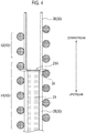
- Fig. 4 is a view showing a configuration around the liquid surface forming location according to Modified Example 2.
- the tubular member 30 includes a first portion 35 extending upstream from the liquid surface forming location, and a second portion 36 extending downstream from the liquid surface forming location.
- a hollow cross-sectional area of the second portion 36 is larger than a hollow cross-sectional area of the first portion 35.
- the liquid surface defining part that defines the liquid surface 21A is constituted by a step 34 formed by a boundary between the first portion 35 and the second portion 36.
- the inner wall of the tubular member 30 has the step 34 having a larger hollow cross-sectional area on the downstream side of the liquid surface forming location than a hollow cross-sectional area on the upstream side of the liquid surface forming location.
- the first portion 35 has a function of transferring the aerosol source 21 to the liquid surface forming location by a capillary phenomenon.
- the second portion 36 has a function of guiding a droplet scattered due to atomization, to a position where the droplet can be heated by a second atomizer 42.
- the first atomizer 41 is arranged around the first portion 35 and the second portion 36 at the liquid surface forming location, and the second atomizer 42 is arranged around the second portion 36, on the downstream side of the liquid surface forming location.
- the first atomizer 41 and the second atomizer 42 are preferably provided continuously over the liquid surface forming location.
- the step 34 is provided as the liquid surface defining part instead of the opening 31, but similar effects to the embodiment can be obtained. Further, since the opening 31 is unnecessary, no droplet leaks from the opening 31.
- the liquid surface defining part that defines the liquid surface 21A is constituted by the opening 31 disposed at the liquid surface forming location.
- a liquid surface defining part that defines a liquid surface 21A is constituted by a step provided on an inner wall of a tubular member 30.
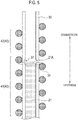
- FIG. 5 is a view showing a configuration around the liquid surface forming location according to Modified Example 3.
- the inner wall of the tubular member 30 has a recess 37 provided at the liquid surface forming location.
- the liquid surface defining part that defines the liquid surface 21A is constituted by a step 34 that is formed by an upstream portion of the recess 37.
- the inner wall of the tubular member 30 has the step 34 having a larger hollow cross-sectional area on the downstream side of the liquid surface forming location than a hollow cross-sectional area on the upstream side of the liquid surface forming location.
- a plurality of recesses 37 may be intermittently provided along a circumferential direction of the tubular member 30.
- a single recess 37 may be continuously provided over the entire circumference of the tubular member 30.
- the upstream portion from the recess 37 has a function of transferring the aerosol source 21 to the liquid surface forming location by a capillary phenomenon.
- a downstream portion from the recess 37 has a function of guiding the a droplet scattered due to atomization, to a position where the droplet can be heated by the second atomizer 42.
- the first atomizer 41 is arranged around the tubular member 30 at the liquid surface forming location, and the second atomizer 42 is arranged around the tubular member 30, on the downstream side of the liquid surface forming location.
- the first atomizer 41 and the second atomizer 42 are preferably provided continuously over the liquid surface forming location.
- the step 34 is provided as the liquid surface defining part instead of the opening 31, but similar effects to the embodiment can be obtained. Further, since the opening 31 is unnecessary, no droplet leaks from the opening 31.
- the liquid surface defining part that defines the liquid surface 21A is constituted by the opening 31 disposed at the liquid surface forming location.
- a property of an inner wall of a tubular member 30 is changed at the liquid surface forming location or on an upstream side of the liquid surface forming location.
- FIG. 6 is a view showing a configuration around a liquid surface forming location according to Modified Example 4.
- the tubular member 30 includes a first portion 301 extending upstream from the liquid surface forming location, a second portion 302 continuous with the first portion 301 and extending downstream from the liquid surface forming location.
- the property of the inner wall of the tubular member 30 is changed at the liquid surface forming location. That is, a property of an inner wall of the second portion 302 is different from a property of an inner wall of the first portion 301.
- the property of the inner wall of the tubular member 30 is changed at the liquid surface forming location, but the property may be changed on the upstream side of the liquid surface forming location.
- the property of the inner wall is a property that affects the capillary phenomenon, for example, wettability of the inner wall against the aerosol source 21.
- wettability of the inner wall of the second portion 302 against the aerosol source 21 is poor as compared to wettability of the inner wall of the first portion 301 against the aerosol source 21.
- the inner wall of the second portion 302 constitutes a liquid surface defining part that defines the liquid surface 21A.
- wettability of the inner wall of the tubular member 30 against the aerosol source 21 depends on a material and a surface roughness of the inner wall of the first portion 301 and the inner wall of the second portion 302.
- the material and the surface roughness of the inner wall of the first portion 301 and the inner wall of the second portion 302 can be changed.
- the first portion 301 has a function of transferring the aerosol source 21 to the liquid surface forming location by a capillary phenomenon.
- the second portion 302 has a function of guiding a droplet scattered due to atomization, to a position where the droplet can be heated by the second atomizer 42.
- the first atomizer 41 is arranged around the first portion 301 and the second portion 302 at the liquid surface forming location, and the second atomizer 42 is arranged around the second portion 302, on the downstream side of the liquid surface forming location.
- the first atomizer 41 and the second atomizer 42 are preferably provided continuously over the liquid surface forming location.
- the liquid surface defining part is constituted by a change in the property of the inner wall of the tubular member 30, but similar effects to the embodiment can be obtained. Further, since the opening 31 is unnecessary, no droplet leaks from the opening 31.
- the tubular member 30 has been exemplified as a transfer unit that forms the liquid surface 21A of the aerosol source 21 at the liquid surface forming location.
- the transfer unit is a fibrous member formed by twisting glass fibers or the like.
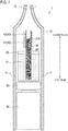
- Fig. 7 is a view showing a flavor inhaler 1 according to Modified Example 5. However, in Fig. 7 , only a part of the flavor inhaler 1 is shown, and a storage container 20, a power source 50, a control circuit 60, and the like are omitted.
- the flavor inhaler 1 has a fibrous member 80 and a holding member 90 instead of the tubular member 30.
- the fibrous member 80 is an example of a transfer unit that transfers an aerosol source 21 to a liquid surface forming location at which a liquid surface 21A of the aerosol source 21 is formed, from upstream of the liquid surface forming location, to form the liquid surface 21A.
- the fibrous member 80 is formed by twisting glass fibers or the like. A capillary phenomenon occurs due to a space between the glass fibers. Therefore, it should be noted that the fibrous member 80 is an example of a columnar member that transfers the aerosol source 21 by a capillary phenomenon, and holds the aerosol source 21 such that the liquid surface 21A of the aerosol source 21 is formed at the liquid surface forming location.
- a liquid surface defining part that defines the liquid surface 21A is constituted by the downstream end of the fibrous member 80.
- the holding member 90 is a member to maintain a shape of the fibrous member 80. Specifically, the holding member 90 has a tubular shape, and the fibrous member 80 is disposed inside the holding member 90.
- the holding member 90 preferably extends downstream of the liquid surface forming location (the downstream end of the fibrous member 80). It should to be noted that a cavity of the holding member 90 has a size that does not cause a capillary phenomenon.
- the first atomizer 41 is arranged around the holding member 90 at the liquid surface forming location, and the second atomizer 42 is arranged around the holding member 90, on the downstream side of the liquid surface forming location.
- the first atomizer 41 and the second atomizer 42 are preferably provided continuously over the liquid surface forming location.
- the holding member 90 may be omitted.
- the first atomizer 41 is arranged around the fibrous member 80 at the liquid surface forming location.
- the second atomizer 42 only needs to be arranged downstream of the liquid surface forming location.
- the second atomizer 42 may be arranged near the suction port 12 on an inner wall of a housing 10.
- the fibrous member 80 is used instead of the tubular member 30, but effects of the embodiment can be obtained.
- a hollow cross-sectional area (cross-sectional area of the fibrous member 80) of the holding member 90 is larger than a hollow cross-sectional area of the tubular member 30, the fibrous member 80 can hold a larger amount of the aerosol source 21 than that in the embodiment.
- the first atomizer 41 and the second atomizer 42 are continuously provided over the liquid surface forming location.
- the first atomizer 41 and the second atomizer 42 may be separate members discontinuous with each other.
- the coil-shaped heater wound around the tubular member 30 or the like has been exemplified as the first atomizer and the second atomizer.
- the first atomizer only needs to have a function of atomizing the aerosol source located upstream of the liquid surface forming location.
- the second atomizer only needs to atomize a droplet located downstream of the liquid surface forming location.
- the first atomizer and the second atomizer may be a heater type atomizer, or may be an ultrasonic type atomizer.
- the type of the first atomizer may be different from the type of the second atomizer.
- the tubular member 30 has a capillary tube that transfers the aerosol source 21 to the liquid surface forming location by a capillary phenomenon, and a guide tube that guides a droplet scattered due to atomization, to a position where the droplet can be heated by the second atomizer 42.
- the capillary tube and the guide tube may be separate members, or may be a same member.
- the capillary tube and the guide tube may or may not be in contact with each other.
- the guide tube may have a capillary function. It should be noted that, even in such a case, the liquid surface 21A is formed at the liquid surface forming location due to the presence of the liquid surface defining part. Further, as in the embodiment ( Fig. 2 ), the tubular member 30 may be a member provided with the opening 31 at the liquid surface forming location of one capillary tube.
- the non-combustion type flavor inhaler capable of suppressing scattering of a droplet having a large particle diameter due to atomization of the aerosol source.
Claims (12)
- Inhalateur d'arôme de type non-combustion (1) comprenant :un réservoir (20) stockant une source d'aérosol (21) ;une unité de transfert (30) transférant la source d'aérosol (21) de l'amont de l'emplacement de formation de surface de liquide à un emplacement de formation de surface de liquide auquel une surface de liquide (21A) de la source d'aérosol (21) est formée, l'unité de transfert (30) étant configurée pour former la surface de liquide (21A) ;un orifice d'aspiration (12) agencé en aval de l'emplacement de formation de surface de liquide ;un premier atomiseur (41) atomisant la source d'aérosol (21) située en amont de l'emplacement de formation de surface de liquide ; etun second atomiseur (42) atomisant une gouttelette générée à partir de la surface de liquide (21A) formée à l'emplacement de formation de surface de liquide, la gouttelette étant située en aval de l'emplacement de formation de surface de liquide.
- Inhalateur d'arôme de type non-combustion (1) selon la revendication 1, dans lequel l'unité de transfert (30) est configurée par un organe colonnaire (30) s'étendant d'amont en aval, l'organe colonnaire (30) tenant la source d'aérosol (21) de telle sorte que la surface de liquide (21A) est formée à l'emplacement de formation de surface de liquide.
- Inhalateur d'arôme de type non-combustion (1) selon la revendication 1 ou 2, dans lequel le premier atomiseur (41) est agencé autour de l'unité de transfert (30) à l'emplacement de formation de surface de liquide, et
le second atomiseur (42) est agencé en aval de l'emplacement de formation de surface de liquide. - Inhalateur d'arôme de type non-combustion (1) selon l'une quelconque des revendications 1 à 3, dans lequel l'unité de transfert (30) transfère la source d'aérosol (21) par un phénomène capillaire.
- Inhalateur d'arôme de type non-combustion (1) selon l'une quelconque des revendications 1 à 4, dans lequel l'unité de transfert (30) est formée par un organe tubulaire (30) transférant la source d'aérosol (21) par un phénomène capillaire.
- Inhalateur d'arôme de type non-combustion (1) selon la revendication 5, dans lequel l'organe tubulaire (30) a une partie de définition de surface de liquide (31, 34) pour définir la surface de liquide (21A) à l'emplacement de formation de surface de liquide, l'organe tubulaire (30) transférant la source d'aérosol (21) à au moins l'emplacement de formation de surface de liquide, l'organe tubulaire (30) incluant une portion s'étendant en aval de l'emplacement de formation de surface de liquide.
- Inhalateur d'arôme de type non-combustion (1) selon la revendication 6, dans lequel la partie de définition de surface de liquide (31, 34) est configurée par une ouverture (31) disposée à l'emplacement de formation de surface de liquide.
- Inhalateur d'arôme de type non-combustion (1) selon la revendication 6, dans lequel une paroi interne de l'organe tubulaire (30) inclut un palier (34) de sorte qu'une aire en coupe creuse d'un côté aval de l'emplacement de formation de surface de liquide est plus grande qu'une aire en coupe creuse du côté amont de l'emplacement de formation de surface de liquide dans une coupe orthogonale, qui est orthogonale à une direction d'amont en aval, et
la partie de définition de surface de liquide (31, 34) est configurée par le palier (34). - Inhalateur d'arôme de type non-combustion (1) selon la revendication 8, dans lequel
l'organe tubulaire (30) comprend :un premier tuyau (32) s'étendant en amont de l'emplacement de formation de surface de liquide ; etun second tuyau (33) s'étendant en aval au moins de l'emplacement de formation de surface de liquide, le second tuyau (33) est agencé à l'extérieur du premier tuyau (32) dans la coupe orthogonale, etle palier (34) est formé par une paroi interne du premier tuyau (32), une extrémité aval du premier tuyau (32), et une paroi interne du second tuyau (33). - Inhalateur d'arôme de type non-combustion (1) selon la revendication 6, dans lequel une propriété d'une paroi interne de l'organe tubulaire (30) est configurée pour changer à l'emplacement de formation de surface de liquide ou d'un côté amont de l'emplacement de formation de surface de liquide.
- Inhalateur d'arôme de type non-combustion (1) selon l'une quelconque des revendications 6 à 10, dans lequel le second atomiseur (42) est agencé autour de l'organe tubulaire (30) d'un côté aval de l'emplacement de formation de surface de liquide.
- Inhalateur d'arôme de type non-combustion (1) selon l'une quelconque des revendications 1 à 11, dans lequel le premier atomiseur (41) et le second atomiseur (42) sont agencés en continu sur l'emplacement de formation de surface de liquide.
Applications Claiming Priority (1)
| Application Number | Priority Date | Filing Date | Title |
|---|---|---|---|
| PCT/JP2015/065659 WO2016194076A1 (fr) | 2015-05-29 | 2015-05-29 | Inhalateur d'arôme sans combustion |
Publications (4)
| Publication Number | Publication Date |
|---|---|
| EP3292772A1 EP3292772A1 (fr) | 2018-03-14 |
| EP3292772A4 EP3292772A4 (fr) | 2019-01-09 |
| EP3292772B1 true EP3292772B1 (fr) | 2020-02-19 |
| EP3292772B8 EP3292772B8 (fr) | 2020-04-01 |
Family
ID=57440282
Family Applications (1)
| Application Number | Title | Priority Date | Filing Date |
|---|---|---|---|
| EP15894111.2A Active EP3292772B8 (fr) | 2015-05-29 | 2015-05-29 | Inhalateur d'arôme sans combustion |
Country Status (5)
| Country | Link |
|---|---|
| US (1) | US10569032B2 (fr) |
| EP (1) | EP3292772B8 (fr) |
| JP (1) | JP6391818B2 (fr) |
| TW (1) | TW201641029A (fr) |
| WO (1) | WO2016194076A1 (fr) |
Families Citing this family (5)
| Publication number | Priority date | Publication date | Assignee | Title |
|---|---|---|---|---|
| EA034513B1 (ru) * | 2015-02-27 | 2020-02-14 | Джапан Тобакко Инк. | Ароматизирующий ингалятор несгораемого типа |
| TWI627911B (zh) * | 2016-12-30 | 2018-07-01 | 日本煙草產業股份有限公司 | 加熱型香味吸嚐器 |
| CN109426171B (zh) * | 2017-09-04 | 2021-10-15 | 卓尔悦欧洲控股有限公司 | 电子烟的控制方法、烟弹组件及电子烟 |
| WO2021053214A1 (fr) * | 2019-09-20 | 2021-03-25 | Nerudia Limited | Appareil de substitution pour fumeur |
| EP3794969A1 (fr) * | 2019-09-20 | 2021-03-24 | Nerudia Limited | Appareil de substitution du tabac |
Family Cites Families (15)
| Publication number | Priority date | Publication date | Assignee | Title |
|---|---|---|---|---|
| US4268460A (en) * | 1977-12-12 | 1981-05-19 | Warner-Lambert Company | Nebulizer |
| US5144962A (en) * | 1989-12-01 | 1992-09-08 | Philip Morris Incorporated | Flavor-delivery article |
| US6386463B1 (en) * | 1996-05-13 | 2002-05-14 | Universidad De Sevilla | Fuel injection nozzle and method of use |
| US6501052B2 (en) * | 2000-12-22 | 2002-12-31 | Chrysalis Technologies Incorporated | Aerosol generator having multiple heating zones and methods of use thereof |
| US7147170B2 (en) * | 2002-09-06 | 2006-12-12 | Philip Morris Usa Inc. | Aerosol generating device and method of use thereof |
| DE60335401D1 (de) | 2002-09-06 | 2011-01-27 | Philip Morris Usa Inc | Aerosolerzeugungsvorrichtungen und verfahren zur erzeugung von aerosolen mit gesteuerten teilchengrössen |
| EP2113178A1 (fr) | 2008-04-30 | 2009-11-04 | Philip Morris Products S.A. | Système de fumée chauffé électriquement avec une portion de stockage liquide |
| KR101540192B1 (ko) * | 2011-08-19 | 2015-07-28 | 니뽄 다바코 산교 가부시키가이샤 | 에어로졸 흡인기 |
| UA112883C2 (uk) | 2011-12-08 | 2016-11-10 | Філіп Морріс Продактс С.А. | Пристрій для утворення аерозолю з капілярним примежовим шаром |
| ES2688362T3 (es) * | 2011-12-08 | 2018-11-02 | Philip Morris Products S.A. | Dispositivo generador de aerosol con tobera de flujo de aire |
| UA113744C2 (xx) | 2011-12-08 | 2017-03-10 | Пристрій для утворення аерозолю з внутрішнім нагрівачем | |
| US20150196055A1 (en) * | 2013-04-15 | 2015-07-16 | Kimree Hi-Tech Inc. | Electronic cigarette |
| WO2015091258A1 (fr) * | 2013-12-19 | 2015-06-25 | Philip Morris Products S.A. | Système de génération d'aérosol pour générer et contrôler la quantité de particules de sel de nicotine |
| CA3114677A1 (fr) * | 2014-05-12 | 2015-11-19 | Loto Labs, Inc. | Dispositif de vaporisateur ameliore |
| RU2701846C2 (ru) * | 2014-12-15 | 2019-10-01 | Филип Моррис Продактс С.А. | Образующая аэрозоль система, использующая эффект вентури для доставки субстрата к нагревательному элементу |
-
2015
- 2015-05-29 EP EP15894111.2A patent/EP3292772B8/fr active Active
- 2015-05-29 WO PCT/JP2015/065659 patent/WO2016194076A1/fr active Application Filing
- 2015-05-29 JP JP2017521341A patent/JP6391818B2/ja active Active
-
2016
- 2016-03-01 TW TW105106098A patent/TW201641029A/zh unknown
-
2017
- 2017-11-28 US US15/824,547 patent/US10569032B2/en active Active
Non-Patent Citations (1)
| Title |
|---|
| None * |
Also Published As
| Publication number | Publication date |
|---|---|
| JP6391818B2 (ja) | 2018-09-19 |
| US20180078718A1 (en) | 2018-03-22 |
| US10569032B2 (en) | 2020-02-25 |
| EP3292772A1 (fr) | 2018-03-14 |
| JPWO2016194076A1 (ja) | 2017-10-26 |
| TW201641029A (zh) | 2016-12-01 |
| EP3292772A4 (fr) | 2019-01-09 |
| EP3292772B8 (fr) | 2020-04-01 |
| WO2016194076A1 (fr) | 2016-12-08 |
Similar Documents
| Publication | Publication Date | Title |
|---|---|---|
| US10569032B2 (en) | Non-combustion type flavor inhaler | |
| US10881137B2 (en) | Flavor inhaler | |
| EP4056059B1 (fr) | Clearomiseur de cigarette électronique rechargeable | |
| US11000071B2 (en) | Electronic smoking device with additive reservoir | |
| EP3135136B1 (fr) | Réservoir de liquide avec deux volumes de stockage et atomiseur/partie de réservoir de liquide ainsi que dispositif à fumer électronique comprenant un réservoir de liquide | |
| EP3135133B1 (fr) | Dispositif à fumer électronique et réservoir d'additif pour dispositif à fumer électronique | |
| US20220142257A1 (en) | Aerosol delivery device | |
| EP3753595A1 (fr) | Dispositif de distribution d'aérosols | |
| EP3827676B1 (fr) | Composant de distribution d'aérosols | |
| EP3753432A1 (fr) | Dispositif de distribution d'aérosols | |
| EP3753430A1 (fr) | Dispositif de distribution d'aérosols | |
| EP3986184B1 (fr) | Dispositif de distribution d'aérosol | |
| WO2020254668A1 (fr) | Dispositif de distribution d'aérosol | |
| US20230021316A1 (en) | Aerosol delivery component | |
| US20230172265A1 (en) | Aerosol delivery component | |
| EP3753431A1 (fr) | Dispositif de distribution d'aérosols |
Legal Events
| Date | Code | Title | Description |
|---|---|---|---|
| STAA | Information on the status of an ep patent application or granted ep patent |
Free format text: STATUS: THE INTERNATIONAL PUBLICATION HAS BEEN MADE |
|
| PUAI | Public reference made under article 153(3) epc to a published international application that has entered the european phase |
Free format text: ORIGINAL CODE: 0009012 |
|
| STAA | Information on the status of an ep patent application or granted ep patent |
Free format text: STATUS: REQUEST FOR EXAMINATION WAS MADE |
|
| 17P | Request for examination filed |
Effective date: 20171130 |
|
| AK | Designated contracting states |
Kind code of ref document: A1 Designated state(s): AL AT BE BG CH CY CZ DE DK EE ES FI FR GB GR HR HU IE IS IT LI LT LU LV MC MK MT NL NO PL PT RO RS SE SI SK SM TR |
|
| AX | Request for extension of the european patent |
Extension state: BA ME |
|
| DAV | Request for validation of the european patent (deleted) | ||
| DAX | Request for extension of the european patent (deleted) | ||
| A4 | Supplementary search report drawn up and despatched |
Effective date: 20181207 |
|
| RIC1 | Information provided on ipc code assigned before grant |
Ipc: A61M 11/00 20060101ALI20181203BHEP Ipc: A61M 15/06 20060101ALI20181203BHEP Ipc: A24F 47/00 20060101AFI20181203BHEP Ipc: A61M 11/04 20060101ALI20181203BHEP |
|
| GRAP | Despatch of communication of intention to grant a patent |
Free format text: ORIGINAL CODE: EPIDOSNIGR1 |
|
| STAA | Information on the status of an ep patent application or granted ep patent |
Free format text: STATUS: GRANT OF PATENT IS INTENDED |
|
| INTG | Intention to grant announced |
Effective date: 20191004 |
|
| GRAS | Grant fee paid |
Free format text: ORIGINAL CODE: EPIDOSNIGR3 |
|
| GRAA | (expected) grant |
Free format text: ORIGINAL CODE: 0009210 |
|
| STAA | Information on the status of an ep patent application or granted ep patent |
Free format text: STATUS: THE PATENT HAS BEEN GRANTED |
|
| AK | Designated contracting states |
Kind code of ref document: B1 Designated state(s): AL AT BE BG CH CY CZ DE DK EE ES FI FR GB GR HR HU IE IS IT LI LT LU LV MC MK MT NL NO PL PT RO RS SE SI SK SM TR |
|
| REG | Reference to a national code |
Ref country code: CH Ref legal event code: EP |
|
| REG | Reference to a national code |
Ref country code: DE Ref legal event code: R096 Ref document number: 602015047554 Country of ref document: DE |
|
| REG | Reference to a national code |
Ref country code: CH Ref legal event code: PK Free format text: BERICHTIGUNG B8 |
|
| REG | Reference to a national code |
Ref country code: AT Ref legal event code: REF Ref document number: 1233942 Country of ref document: AT Kind code of ref document: T Effective date: 20200315 |
|
| REG | Reference to a national code |
Ref country code: IE Ref legal event code: FG4D |
|
| REG | Reference to a national code |
Ref country code: NL Ref legal event code: MP Effective date: 20200219 |
|
| PG25 | Lapsed in a contracting state [announced via postgrant information from national office to epo] |
Ref country code: RS Free format text: LAPSE BECAUSE OF FAILURE TO SUBMIT A TRANSLATION OF THE DESCRIPTION OR TO PAY THE FEE WITHIN THE PRESCRIBED TIME-LIMIT Effective date: 20200219 Ref country code: FI Free format text: LAPSE BECAUSE OF FAILURE TO SUBMIT A TRANSLATION OF THE DESCRIPTION OR TO PAY THE FEE WITHIN THE PRESCRIBED TIME-LIMIT Effective date: 20200219 Ref country code: NO Free format text: LAPSE BECAUSE OF FAILURE TO SUBMIT A TRANSLATION OF THE DESCRIPTION OR TO PAY THE FEE WITHIN THE PRESCRIBED TIME-LIMIT Effective date: 20200519 |
|
| REG | Reference to a national code |
Ref country code: LT Ref legal event code: MG4D |
|
| PG25 | Lapsed in a contracting state [announced via postgrant information from national office to epo] |
Ref country code: IS Free format text: LAPSE BECAUSE OF FAILURE TO SUBMIT A TRANSLATION OF THE DESCRIPTION OR TO PAY THE FEE WITHIN THE PRESCRIBED TIME-LIMIT Effective date: 20200619 Ref country code: BG Free format text: LAPSE BECAUSE OF FAILURE TO SUBMIT A TRANSLATION OF THE DESCRIPTION OR TO PAY THE FEE WITHIN THE PRESCRIBED TIME-LIMIT Effective date: 20200519 Ref country code: GR Free format text: LAPSE BECAUSE OF FAILURE TO SUBMIT A TRANSLATION OF THE DESCRIPTION OR TO PAY THE FEE WITHIN THE PRESCRIBED TIME-LIMIT Effective date: 20200520 Ref country code: SE Free format text: LAPSE BECAUSE OF FAILURE TO SUBMIT A TRANSLATION OF THE DESCRIPTION OR TO PAY THE FEE WITHIN THE PRESCRIBED TIME-LIMIT Effective date: 20200219 Ref country code: HR Free format text: LAPSE BECAUSE OF FAILURE TO SUBMIT A TRANSLATION OF THE DESCRIPTION OR TO PAY THE FEE WITHIN THE PRESCRIBED TIME-LIMIT Effective date: 20200219 Ref country code: LV Free format text: LAPSE BECAUSE OF FAILURE TO SUBMIT A TRANSLATION OF THE DESCRIPTION OR TO PAY THE FEE WITHIN THE PRESCRIBED TIME-LIMIT Effective date: 20200219 |
|
| PG25 | Lapsed in a contracting state [announced via postgrant information from national office to epo] |
Ref country code: NL Free format text: LAPSE BECAUSE OF FAILURE TO SUBMIT A TRANSLATION OF THE DESCRIPTION OR TO PAY THE FEE WITHIN THE PRESCRIBED TIME-LIMIT Effective date: 20200219 |
|
| PG25 | Lapsed in a contracting state [announced via postgrant information from national office to epo] |
Ref country code: SM Free format text: LAPSE BECAUSE OF FAILURE TO SUBMIT A TRANSLATION OF THE DESCRIPTION OR TO PAY THE FEE WITHIN THE PRESCRIBED TIME-LIMIT Effective date: 20200219 Ref country code: EE Free format text: LAPSE BECAUSE OF FAILURE TO SUBMIT A TRANSLATION OF THE DESCRIPTION OR TO PAY THE FEE WITHIN THE PRESCRIBED TIME-LIMIT Effective date: 20200219 Ref country code: DK Free format text: LAPSE BECAUSE OF FAILURE TO SUBMIT A TRANSLATION OF THE DESCRIPTION OR TO PAY THE FEE WITHIN THE PRESCRIBED TIME-LIMIT Effective date: 20200219 Ref country code: RO Free format text: LAPSE BECAUSE OF FAILURE TO SUBMIT A TRANSLATION OF THE DESCRIPTION OR TO PAY THE FEE WITHIN THE PRESCRIBED TIME-LIMIT Effective date: 20200219 Ref country code: PT Free format text: LAPSE BECAUSE OF FAILURE TO SUBMIT A TRANSLATION OF THE DESCRIPTION OR TO PAY THE FEE WITHIN THE PRESCRIBED TIME-LIMIT Effective date: 20200712 Ref country code: CZ Free format text: LAPSE BECAUSE OF FAILURE TO SUBMIT A TRANSLATION OF THE DESCRIPTION OR TO PAY THE FEE WITHIN THE PRESCRIBED TIME-LIMIT Effective date: 20200219 Ref country code: SK Free format text: LAPSE BECAUSE OF FAILURE TO SUBMIT A TRANSLATION OF THE DESCRIPTION OR TO PAY THE FEE WITHIN THE PRESCRIBED TIME-LIMIT Effective date: 20200219 Ref country code: LT Free format text: LAPSE BECAUSE OF FAILURE TO SUBMIT A TRANSLATION OF THE DESCRIPTION OR TO PAY THE FEE WITHIN THE PRESCRIBED TIME-LIMIT Effective date: 20200219 Ref country code: ES Free format text: LAPSE BECAUSE OF FAILURE TO SUBMIT A TRANSLATION OF THE DESCRIPTION OR TO PAY THE FEE WITHIN THE PRESCRIBED TIME-LIMIT Effective date: 20200219 |
|
| REG | Reference to a national code |
Ref country code: AT Ref legal event code: MK05 Ref document number: 1233942 Country of ref document: AT Kind code of ref document: T Effective date: 20200219 |
|
| REG | Reference to a national code |
Ref country code: DE Ref legal event code: R097 Ref document number: 602015047554 Country of ref document: DE |
|
| PLBE | No opposition filed within time limit |
Free format text: ORIGINAL CODE: 0009261 |
|
| STAA | Information on the status of an ep patent application or granted ep patent |
Free format text: STATUS: NO OPPOSITION FILED WITHIN TIME LIMIT |
|
| 26N | No opposition filed |
Effective date: 20201120 |
|
| PG25 | Lapsed in a contracting state [announced via postgrant information from national office to epo] |
Ref country code: CH Free format text: LAPSE BECAUSE OF NON-PAYMENT OF DUE FEES Effective date: 20200531 Ref country code: AT Free format text: LAPSE BECAUSE OF FAILURE TO SUBMIT A TRANSLATION OF THE DESCRIPTION OR TO PAY THE FEE WITHIN THE PRESCRIBED TIME-LIMIT Effective date: 20200219 Ref country code: IT Free format text: LAPSE BECAUSE OF FAILURE TO SUBMIT A TRANSLATION OF THE DESCRIPTION OR TO PAY THE FEE WITHIN THE PRESCRIBED TIME-LIMIT Effective date: 20200219 Ref country code: MC Free format text: LAPSE BECAUSE OF FAILURE TO SUBMIT A TRANSLATION OF THE DESCRIPTION OR TO PAY THE FEE WITHIN THE PRESCRIBED TIME-LIMIT Effective date: 20200219 Ref country code: LI Free format text: LAPSE BECAUSE OF NON-PAYMENT OF DUE FEES Effective date: 20200531 |
|
| PG25 | Lapsed in a contracting state [announced via postgrant information from national office to epo] |
Ref country code: SI Free format text: LAPSE BECAUSE OF FAILURE TO SUBMIT A TRANSLATION OF THE DESCRIPTION OR TO PAY THE FEE WITHIN THE PRESCRIBED TIME-LIMIT Effective date: 20200219 Ref country code: PL Free format text: LAPSE BECAUSE OF FAILURE TO SUBMIT A TRANSLATION OF THE DESCRIPTION OR TO PAY THE FEE WITHIN THE PRESCRIBED TIME-LIMIT Effective date: 20200219 |
|
| REG | Reference to a national code |
Ref country code: BE Ref legal event code: MM Effective date: 20200531 |
|
| PG25 | Lapsed in a contracting state [announced via postgrant information from national office to epo] |
Ref country code: LU Free format text: LAPSE BECAUSE OF NON-PAYMENT OF DUE FEES Effective date: 20200529 |
|
| PG25 | Lapsed in a contracting state [announced via postgrant information from national office to epo] |
Ref country code: IE Free format text: LAPSE BECAUSE OF NON-PAYMENT OF DUE FEES Effective date: 20200529 |
|
| PG25 | Lapsed in a contracting state [announced via postgrant information from national office to epo] |
Ref country code: BE Free format text: LAPSE BECAUSE OF NON-PAYMENT OF DUE FEES Effective date: 20200531 |
|
| PG25 | Lapsed in a contracting state [announced via postgrant information from national office to epo] |
Ref country code: TR Free format text: LAPSE BECAUSE OF FAILURE TO SUBMIT A TRANSLATION OF THE DESCRIPTION OR TO PAY THE FEE WITHIN THE PRESCRIBED TIME-LIMIT Effective date: 20200219 Ref country code: MT Free format text: LAPSE BECAUSE OF FAILURE TO SUBMIT A TRANSLATION OF THE DESCRIPTION OR TO PAY THE FEE WITHIN THE PRESCRIBED TIME-LIMIT Effective date: 20200219 Ref country code: CY Free format text: LAPSE BECAUSE OF FAILURE TO SUBMIT A TRANSLATION OF THE DESCRIPTION OR TO PAY THE FEE WITHIN THE PRESCRIBED TIME-LIMIT Effective date: 20200219 |
|
| PG25 | Lapsed in a contracting state [announced via postgrant information from national office to epo] |
Ref country code: MK Free format text: LAPSE BECAUSE OF FAILURE TO SUBMIT A TRANSLATION OF THE DESCRIPTION OR TO PAY THE FEE WITHIN THE PRESCRIBED TIME-LIMIT Effective date: 20200219 Ref country code: AL Free format text: LAPSE BECAUSE OF FAILURE TO SUBMIT A TRANSLATION OF THE DESCRIPTION OR TO PAY THE FEE WITHIN THE PRESCRIBED TIME-LIMIT Effective date: 20200219 |
|
| PGFP | Annual fee paid to national office [announced via postgrant information from national office to epo] |
Ref country code: FR Payment date: 20221222 Year of fee payment: 9 |
|
| P01 | Opt-out of the competence of the unified patent court (upc) registered |
Effective date: 20230530 |
|
| PGFP | Annual fee paid to national office [announced via postgrant information from national office to epo] |
Ref country code: DE Payment date: 20220620 Year of fee payment: 9 |
|
| PGFP | Annual fee paid to national office [announced via postgrant information from national office to epo] |
Ref country code: GB Payment date: 20230524 Year of fee payment: 9 |