EP3292323B1 - Method and device for controlling the torque of a vehicle powertrain in the event of unavailability of information from the gearbox computer - Google Patents
Method and device for controlling the torque of a vehicle powertrain in the event of unavailability of information from the gearbox computer Download PDFInfo
- Publication number
- EP3292323B1 EP3292323B1 EP16721193.7A EP16721193A EP3292323B1 EP 3292323 B1 EP3292323 B1 EP 3292323B1 EP 16721193 A EP16721193 A EP 16721193A EP 3292323 B1 EP3292323 B1 EP 3292323B1
- Authority
- EP
- European Patent Office
- Prior art keywords
- computer
- ratio
- torque
- setpoint
- engaged
- Prior art date
- Legal status (The legal status is an assumption and is not a legal conclusion. Google has not performed a legal analysis and makes no representation as to the accuracy of the status listed.)
- Active
Links
- 238000000034 method Methods 0.000 title claims description 17
- 238000012544 monitoring process Methods 0.000 claims 3
- 238000011194 good manufacturing practice Methods 0.000 description 27
- 230000006870 function Effects 0.000 description 17
- 230000005540 biological transmission Effects 0.000 description 11
- 238000003860 storage Methods 0.000 description 11
- 230000008878 coupling Effects 0.000 description 6
- 238000010168 coupling process Methods 0.000 description 6
- 238000005859 coupling reaction Methods 0.000 description 6
- 239000007858 starting material Substances 0.000 description 5
- 238000004146 energy storage Methods 0.000 description 4
- 238000004891 communication Methods 0.000 description 3
- 230000009977 dual effect Effects 0.000 description 2
- 239000000126 substance Substances 0.000 description 2
- 241000287107 Passer Species 0.000 description 1
- 241001652065 Trigonopeltastes delta Species 0.000 description 1
- 230000004913 activation Effects 0.000 description 1
- 238000010276 construction Methods 0.000 description 1
- 238000009795 derivation Methods 0.000 description 1
- 238000006073 displacement reaction Methods 0.000 description 1
- 239000000446 fuel Substances 0.000 description 1
- 238000004519 manufacturing process Methods 0.000 description 1
- 230000007246 mechanism Effects 0.000 description 1
- 238000009987 spinning Methods 0.000 description 1
- 230000001960 triggered effect Effects 0.000 description 1
Images

Classifications
-
- F—MECHANICAL ENGINEERING; LIGHTING; HEATING; WEAPONS; BLASTING
- F16—ENGINEERING ELEMENTS AND UNITS; GENERAL MEASURES FOR PRODUCING AND MAINTAINING EFFECTIVE FUNCTIONING OF MACHINES OR INSTALLATIONS; THERMAL INSULATION IN GENERAL
- F16H—GEARING
- F16H61/00—Control functions within control units of change-speed- or reversing-gearings for conveying rotary motion ; Control of exclusively fluid gearing, friction gearing, gearings with endless flexible members or other particular types of gearing
- F16H61/12—Detecting malfunction or potential malfunction, e.g. fail safe; Circumventing or fixing failures
-
- B—PERFORMING OPERATIONS; TRANSPORTING
- B60—VEHICLES IN GENERAL
- B60K—ARRANGEMENT OR MOUNTING OF PROPULSION UNITS OR OF TRANSMISSIONS IN VEHICLES; ARRANGEMENT OR MOUNTING OF PLURAL DIVERSE PRIME-MOVERS IN VEHICLES; AUXILIARY DRIVES FOR VEHICLES; INSTRUMENTATION OR DASHBOARDS FOR VEHICLES; ARRANGEMENTS IN CONNECTION WITH COOLING, AIR INTAKE, GAS EXHAUST OR FUEL SUPPLY OF PROPULSION UNITS IN VEHICLES
- B60K6/00—Arrangement or mounting of plural diverse prime-movers for mutual or common propulsion, e.g. hybrid propulsion systems comprising electric motors and internal combustion engines ; Control systems therefor, i.e. systems controlling two or more prime movers, or controlling one of these prime movers and any of the transmission, drive or drive units Informative references: mechanical gearings with secondary electric drive F16H3/72; arrangements for handling mechanical energy structurally associated with the dynamo-electric machine H02K7/00; machines comprising structurally interrelated motor and generator parts H02K51/00; dynamo-electric machines not otherwise provided for in H02K see H02K99/00
- B60K6/20—Arrangement or mounting of plural diverse prime-movers for mutual or common propulsion, e.g. hybrid propulsion systems comprising electric motors and internal combustion engines ; Control systems therefor, i.e. systems controlling two or more prime movers, or controlling one of these prime movers and any of the transmission, drive or drive units Informative references: mechanical gearings with secondary electric drive F16H3/72; arrangements for handling mechanical energy structurally associated with the dynamo-electric machine H02K7/00; machines comprising structurally interrelated motor and generator parts H02K51/00; dynamo-electric machines not otherwise provided for in H02K see H02K99/00 the prime-movers consisting of electric motors and internal combustion engines, e.g. HEVs
- B60K6/50—Architecture of the driveline characterised by arrangement or kind of transmission units
- B60K6/52—Driving a plurality of drive axles, e.g. four-wheel drive
-
- B—PERFORMING OPERATIONS; TRANSPORTING
- B60—VEHICLES IN GENERAL
- B60K—ARRANGEMENT OR MOUNTING OF PROPULSION UNITS OR OF TRANSMISSIONS IN VEHICLES; ARRANGEMENT OR MOUNTING OF PLURAL DIVERSE PRIME-MOVERS IN VEHICLES; AUXILIARY DRIVES FOR VEHICLES; INSTRUMENTATION OR DASHBOARDS FOR VEHICLES; ARRANGEMENTS IN CONNECTION WITH COOLING, AIR INTAKE, GAS EXHAUST OR FUEL SUPPLY OF PROPULSION UNITS IN VEHICLES
- B60K6/00—Arrangement or mounting of plural diverse prime-movers for mutual or common propulsion, e.g. hybrid propulsion systems comprising electric motors and internal combustion engines ; Control systems therefor, i.e. systems controlling two or more prime movers, or controlling one of these prime movers and any of the transmission, drive or drive units Informative references: mechanical gearings with secondary electric drive F16H3/72; arrangements for handling mechanical energy structurally associated with the dynamo-electric machine H02K7/00; machines comprising structurally interrelated motor and generator parts H02K51/00; dynamo-electric machines not otherwise provided for in H02K see H02K99/00
- B60K6/20—Arrangement or mounting of plural diverse prime-movers for mutual or common propulsion, e.g. hybrid propulsion systems comprising electric motors and internal combustion engines ; Control systems therefor, i.e. systems controlling two or more prime movers, or controlling one of these prime movers and any of the transmission, drive or drive units Informative references: mechanical gearings with secondary electric drive F16H3/72; arrangements for handling mechanical energy structurally associated with the dynamo-electric machine H02K7/00; machines comprising structurally interrelated motor and generator parts H02K51/00; dynamo-electric machines not otherwise provided for in H02K see H02K99/00 the prime-movers consisting of electric motors and internal combustion engines, e.g. HEVs
- B60K6/50—Architecture of the driveline characterised by arrangement or kind of transmission units
- B60K6/54—Transmission for changing ratio
- B60K6/547—Transmission for changing ratio the transmission being a stepped gearing
-
- B—PERFORMING OPERATIONS; TRANSPORTING
- B60—VEHICLES IN GENERAL
- B60W—CONJOINT CONTROL OF VEHICLE SUB-UNITS OF DIFFERENT TYPE OR DIFFERENT FUNCTION; CONTROL SYSTEMS SPECIALLY ADAPTED FOR HYBRID VEHICLES; ROAD VEHICLE DRIVE CONTROL SYSTEMS FOR PURPOSES NOT RELATED TO THE CONTROL OF A PARTICULAR SUB-UNIT
- B60W10/00—Conjoint control of vehicle sub-units of different type or different function
- B60W10/04—Conjoint control of vehicle sub-units of different type or different function including control of propulsion units
- B60W10/06—Conjoint control of vehicle sub-units of different type or different function including control of propulsion units including control of combustion engines
-
- B—PERFORMING OPERATIONS; TRANSPORTING
- B60—VEHICLES IN GENERAL
- B60W—CONJOINT CONTROL OF VEHICLE SUB-UNITS OF DIFFERENT TYPE OR DIFFERENT FUNCTION; CONTROL SYSTEMS SPECIALLY ADAPTED FOR HYBRID VEHICLES; ROAD VEHICLE DRIVE CONTROL SYSTEMS FOR PURPOSES NOT RELATED TO THE CONTROL OF A PARTICULAR SUB-UNIT
- B60W10/00—Conjoint control of vehicle sub-units of different type or different function
- B60W10/04—Conjoint control of vehicle sub-units of different type or different function including control of propulsion units
- B60W10/08—Conjoint control of vehicle sub-units of different type or different function including control of propulsion units including control of electric propulsion units, e.g. motors or generators
-
- B—PERFORMING OPERATIONS; TRANSPORTING
- B60—VEHICLES IN GENERAL
- B60W—CONJOINT CONTROL OF VEHICLE SUB-UNITS OF DIFFERENT TYPE OR DIFFERENT FUNCTION; CONTROL SYSTEMS SPECIALLY ADAPTED FOR HYBRID VEHICLES; ROAD VEHICLE DRIVE CONTROL SYSTEMS FOR PURPOSES NOT RELATED TO THE CONTROL OF A PARTICULAR SUB-UNIT
- B60W10/00—Conjoint control of vehicle sub-units of different type or different function
- B60W10/10—Conjoint control of vehicle sub-units of different type or different function including control of change-speed gearings
- B60W10/11—Stepped gearings
-
- B—PERFORMING OPERATIONS; TRANSPORTING
- B60—VEHICLES IN GENERAL
- B60W—CONJOINT CONTROL OF VEHICLE SUB-UNITS OF DIFFERENT TYPE OR DIFFERENT FUNCTION; CONTROL SYSTEMS SPECIALLY ADAPTED FOR HYBRID VEHICLES; ROAD VEHICLE DRIVE CONTROL SYSTEMS FOR PURPOSES NOT RELATED TO THE CONTROL OF A PARTICULAR SUB-UNIT
- B60W20/00—Control systems specially adapted for hybrid vehicles
- B60W20/50—Control strategies for responding to system failures, e.g. for fault diagnosis, failsafe operation or limp mode
-
- B—PERFORMING OPERATIONS; TRANSPORTING
- B60—VEHICLES IN GENERAL
- B60W—CONJOINT CONTROL OF VEHICLE SUB-UNITS OF DIFFERENT TYPE OR DIFFERENT FUNCTION; CONTROL SYSTEMS SPECIALLY ADAPTED FOR HYBRID VEHICLES; ROAD VEHICLE DRIVE CONTROL SYSTEMS FOR PURPOSES NOT RELATED TO THE CONTROL OF A PARTICULAR SUB-UNIT
- B60W50/00—Details of control systems for road vehicle drive control not related to the control of a particular sub-unit, e.g. process diagnostic or vehicle driver interfaces
- B60W50/02—Ensuring safety in case of control system failures, e.g. by diagnosing, circumventing or fixing failures
- B60W50/029—Adapting to failures or work around with other constraints, e.g. circumvention by avoiding use of failed parts
-
- B—PERFORMING OPERATIONS; TRANSPORTING
- B60—VEHICLES IN GENERAL
- B60W—CONJOINT CONTROL OF VEHICLE SUB-UNITS OF DIFFERENT TYPE OR DIFFERENT FUNCTION; CONTROL SYSTEMS SPECIALLY ADAPTED FOR HYBRID VEHICLES; ROAD VEHICLE DRIVE CONTROL SYSTEMS FOR PURPOSES NOT RELATED TO THE CONTROL OF A PARTICULAR SUB-UNIT
- B60W50/00—Details of control systems for road vehicle drive control not related to the control of a particular sub-unit, e.g. process diagnostic or vehicle driver interfaces
- B60W50/08—Interaction between the driver and the control system
- B60W50/14—Means for informing the driver, warning the driver or prompting a driver intervention
-
- B—PERFORMING OPERATIONS; TRANSPORTING
- B60—VEHICLES IN GENERAL
- B60K—ARRANGEMENT OR MOUNTING OF PROPULSION UNITS OR OF TRANSMISSIONS IN VEHICLES; ARRANGEMENT OR MOUNTING OF PLURAL DIVERSE PRIME-MOVERS IN VEHICLES; AUXILIARY DRIVES FOR VEHICLES; INSTRUMENTATION OR DASHBOARDS FOR VEHICLES; ARRANGEMENTS IN CONNECTION WITH COOLING, AIR INTAKE, GAS EXHAUST OR FUEL SUPPLY OF PROPULSION UNITS IN VEHICLES
- B60K17/00—Arrangement or mounting of transmissions in vehicles
- B60K17/34—Arrangement or mounting of transmissions in vehicles for driving both front and rear wheels, e.g. four wheel drive vehicles
- B60K17/356—Arrangement or mounting of transmissions in vehicles for driving both front and rear wheels, e.g. four wheel drive vehicles having fluid or electric motor, for driving one or more wheels
-
- B—PERFORMING OPERATIONS; TRANSPORTING
- B60—VEHICLES IN GENERAL
- B60W—CONJOINT CONTROL OF VEHICLE SUB-UNITS OF DIFFERENT TYPE OR DIFFERENT FUNCTION; CONTROL SYSTEMS SPECIALLY ADAPTED FOR HYBRID VEHICLES; ROAD VEHICLE DRIVE CONTROL SYSTEMS FOR PURPOSES NOT RELATED TO THE CONTROL OF A PARTICULAR SUB-UNIT
- B60W2510/00—Input parameters relating to a particular sub-units
- B60W2510/10—Change speed gearings
- B60W2510/1005—Transmission ratio engaged
-
- B—PERFORMING OPERATIONS; TRANSPORTING
- B60—VEHICLES IN GENERAL
- B60W—CONJOINT CONTROL OF VEHICLE SUB-UNITS OF DIFFERENT TYPE OR DIFFERENT FUNCTION; CONTROL SYSTEMS SPECIALLY ADAPTED FOR HYBRID VEHICLES; ROAD VEHICLE DRIVE CONTROL SYSTEMS FOR PURPOSES NOT RELATED TO THE CONTROL OF A PARTICULAR SUB-UNIT
- B60W2710/00—Output or target parameters relating to a particular sub-units
- B60W2710/10—Change speed gearings
- B60W2710/1005—Transmission ratio engaged
-
- F—MECHANICAL ENGINEERING; LIGHTING; HEATING; WEAPONS; BLASTING
- F16—ENGINEERING ELEMENTS AND UNITS; GENERAL MEASURES FOR PRODUCING AND MAINTAINING EFFECTIVE FUNCTIONING OF MACHINES OR INSTALLATIONS; THERMAL INSULATION IN GENERAL
- F16H—GEARING
- F16H61/00—Control functions within control units of change-speed- or reversing-gearings for conveying rotary motion ; Control of exclusively fluid gearing, friction gearing, gearings with endless flexible members or other particular types of gearing
- F16H61/12—Detecting malfunction or potential malfunction, e.g. fail safe; Circumventing or fixing failures
- F16H2061/1224—Adapting to failures or work around with other constraints, e.g. circumvention by avoiding use of failed parts
-
- F—MECHANICAL ENGINEERING; LIGHTING; HEATING; WEAPONS; BLASTING
- F16—ENGINEERING ELEMENTS AND UNITS; GENERAL MEASURES FOR PRODUCING AND MAINTAINING EFFECTIVE FUNCTIONING OF MACHINES OR INSTALLATIONS; THERMAL INSULATION IN GENERAL
- F16H—GEARING
- F16H59/00—Control inputs to control units of change-speed-, or reversing-gearings for conveying rotary motion
- F16H59/68—Inputs being a function of gearing status
- F16H59/70—Inputs being a function of gearing status dependent on the ratio established
-
- Y—GENERAL TAGGING OF NEW TECHNOLOGICAL DEVELOPMENTS; GENERAL TAGGING OF CROSS-SECTIONAL TECHNOLOGIES SPANNING OVER SEVERAL SECTIONS OF THE IPC; TECHNICAL SUBJECTS COVERED BY FORMER USPC CROSS-REFERENCE ART COLLECTIONS [XRACs] AND DIGESTS
- Y02—TECHNOLOGIES OR APPLICATIONS FOR MITIGATION OR ADAPTATION AGAINST CLIMATE CHANGE
- Y02T—CLIMATE CHANGE MITIGATION TECHNOLOGIES RELATED TO TRANSPORTATION
- Y02T10/00—Road transport of goods or passengers
- Y02T10/60—Other road transportation technologies with climate change mitigation effect
- Y02T10/62—Hybrid vehicles
Definitions
- the invention relates to vehicles comprising a powertrain (or GMP) coupled to a gearbox, and more precisely the control of the torque which is produced by the GMP (see for example US5033328A or US2012 / 302399A ).
- “gearbox” means equipment which variably transforms the torque produced by the GMP into torque for means of displacement (such as wheels) of a vehicle as a function of the ratio (or speed). engaged which is imposed on it by a dedicated computer at the request of another computer supervising the operation of the GMP. Consequently, it could be, for example, an automatic gearbox (or BVA) or a piloted manual gearbox (BVMP or DCT (dual clutch gearbox)), as soon as it receives its commands from a dedicated computer which does not directly decide on the report it must initiate but receives reporting instructions to be engaged from the computer supervising the operation of the GMP.
- BVA automatic gearbox
- BVMP or DCT dual clutch gearbox
- the computer which supervises the operation of the GMP, determines a torque setpoint, defining the torque that the GMP must produce, in particular as a function of first and second information which is provided by the gearbox dedicated computer.
- the first information is representative of the report which is actually engaged in the gearbox and the second information is representative of a target report which is defined by the very last report instruction to be engaged provided by the computer supervising the operation of the GMP.
- the computer supervising the operation of the GMP can no longer determine the torque setpoint. This can result in a loss of the torque produced by the GMP, which can prove dangerous for the passengers of the vehicle (especially in a phase of overtaking or clearing a dangerous situation).
- the invention therefore aims in particular to improve the situation.
- This method is characterized by the fact that it comprises a step in which, in the absence of the first and second information, the first computer determines the torque setpoint as a function of two gear setpoints to be engaged previously supplied to the first and second previous moments chosen to replace the first and second information respectively.
- this first computer can continue to develop torque settings and thus allow the GMP to substantially maintain its nominal performance.
- the invention also provides a control device intended to equip a first computer supervising the operation of a vehicle powertrain capable of producing a torque as a function of a determined torque setpoint, and coupled to a gearbox whose ratios are controlled, as a function of a gear setpoint to be engaged provided by the first computer, by a second computer providing the latter with first information representative of the ratio actually engaged and a second information representative of a target ratio useful for determining said torque setpoint.
- This device is characterized by the fact that it is arranged, in the absence of the first and second information, to determine the torque setpoint as a function of two gear setpoints to be engaged previously supplied at the first and second previous moments chosen to replace first and second information respectively.
- the invention also provides a computer, on the one hand, intended for supervise the operation of a vehicle powertrain capable of producing a torque according to a determined torque setpoint and coupled to a gearbox whose gears are controlled, according to a gear setpoint to be engaged, by a second computer supplying a first item of information representative of the ratio actually engaged and a second item of information representative of a target ratio useful for determining the torque setpoint, and, on the other hand, comprising a control device of the type of that presented above before.
- the invention also provides a vehicle, possibly of the automobile type, and comprising, on the one hand, a powertrain capable of producing a torque as a function of a determined torque setpoint and coupled to a gearbox whose ratios are controlled , as a function of a gear setpoint to be engaged, by a computer providing first information representative of the gear actually engaged and a second information representative of a target gear useful for determining the torque setpoint, and, on the other hand , another computer of the type presented above and suitable for determining the torque setpoint.
- the object of the invention is to propose a control method, and an associated DC control device, intended to control the torque which is produced by a powertrain (or GMP) of a vehicle V.
- vehicle V is of the automobile type.
- it is a car.
- the invention is not limited to this type of vehicle. It relates in fact to any vehicle having a powertrain intended to produce torque, by example for spinning wheels or a propeller. Consequently, the invention relates in particular to land vehicles (cars, motorcycles, utility vehicles, coaches (or buses), trucks, road vehicles, construction equipment, handling equipment, trains), river or maritime vehicles, and aircraft.
- the powertrain (or GMP) is of the hybrid type, and therefore comprises at least one heat engine MT, coupled to a gearbox BV, and at least one non-thermal MM motor.
- heat engine is understood here to mean an engine consuming fuel or chemicals. Consequently, in the aeronautical field, it may in particular be a reactor, a turbojet engine or a chemical engine.
- driving machine is understood here to mean a non-thermal machine or engine intended to supply torque for moving a vehicle, either alone or in addition to a thermal engine. Consequently, it may for example be an electric motor, a hydraulic machine, a pneumatic machine or a flywheel. It will be noted that this motive machine MM is not coupled to the heat engine MT.
- the invention is not limited to hybrid GMPs. It also relates to traditional GMPs, that is to say comprising at least one MT heat engine coupled to a BV gearbox, provided that the transmission report setpoints are done in a computer external to the computer which is dedicated to the gearbox.
- the motor machine MM is of the electric type. But as indicated above, this driving machine could be of another type.
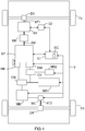
- a vehicle V comprising a transmission chain comprising, for example, a powertrain (or GMP), here of the hybrid type, a first computer C1 suitable for supervising (or managing) the operation of the GMP, an EM clutch, a BV gearbox, a second computer C2 dedicated to the BV gearbox, a coupling / decoupling means MC for the motor engine MM of the GMP, and a DC control device according to the invention.
- a powertrain or GMP
- GMP powertrain
- the GMP (here hybrid type) includes in particular a heat engine MT, a motor shaft AM, an electric machine ME, at least one motive machine MM (here an electric motor), first means of energy storage (here electric) MS1, second electrical energy storage means MS2 to which an electrical power supply network (not shown) is coupled.
- the motor machine MM is coupled to the first energy storage means MS1 which are, for example, of the low voltage type (for example around 220 V). As illustrated, this coupling can be done via an ON / DC type DC inverter.
- the transmission chain also includes a starter DM and, here, first AT1 and second AT2 transmission shafts, by way of nonlimiting example.
- the first transmission shaft AT1 is responsible for rotating the wheels of the front axle TV of the vehicle V (preferably via a front differential DV), while the second transmission shaft AT2 is responsible for driving the rotation the rear axle wheels TR of vehicle V (preferably via a rear differential DR).
- the reverse is also possible.
- the heat engine MT comprises a crankshaft (not shown) which is fixedly secured to an AM engine shaft in order to drive the latter (AM) in rotation.
- the gearbox BV comprises at least one input shaft (or primary) intended to receive the torque produced by the heat engine MT via the clutch EM, and an output shaft intended to receive this torque via the drive shaft input in order to communicate it to the first transmission shaft AT1 to which it is coupled and which is indirectly coupled to the front wheels (here) of the vehicle V via the front differential DV.
- the clutch EM comprises a flywheel fixedly attached to the engine shaft AM and a clutch disc fixedly attached to the input shaft of the gearbox BV.
- the gearbox BV can be an automatic gearbox (or BVA) or a piloted manual gearbox (BVMP or DCT (dual clutch transmission)), since it receives its commands from the second computer C2 dedicated to it and which does not decide directly from the report that must engage but receives report instructions to initiate the re c part of the first computer C1 which supervises the operation of the GMP.
- BVA automatic gearbox
- BVMP piloted manual gearbox
- DCT dual clutch transmission
- the ME electric machine is coupled to the MT heat engine, for example via a front strap. It is, for example, an alternator-starter responsible for launching the thermal engine MT in order to allow it to start, including in the presence of a stop control system and automatic restart (or “stop and start ”), and to produce a torque intended to be transmitted to the first transmission shaft AT1 via the clutch EM and the gearbox BV.
- This torque production is done thanks to the energy which is stored in the first storage means MS1, as well as thanks to the energy which is supplied directly by the motor machine MM, if the latter is controlled in generator mode, and without requesting the energy present in the first storage means MS1 (this is called power derivation).
- the coupling / decoupling means MC is here responsible for coupling / decoupling the motor machine MM to / from the second transmission shaft AT2, on the order of the first computer C1, in order to communicate the torque that it produces, thanks to the stored energy. in the first storage means MS1, to the second transmission shaft AT2 which is indirectly coupled to the rear wheels (here) of the vehicle V via the rear differential DR.
- This coupling / decoupling means MC is for example a dog clutch mechanism or else a clutch or a hydraulic torque converter.
- the starter DM is responsible for starting the thermal engine MT when the driver makes an activation request by means of a start key or button (or “push”).
- This DM starter is coupled to the second storage means MS2, preferably via a CV converter of the DC / DC type.
- the latter can also be coupled, as shown without limitation, to the inverter ON and to the first electrical energy storage means MS1.
- the second storage means MS2 are arranged in the form of a very low voltage type battery (for example 12 V, 24 V or 48 V).
- the electrical supply network (or on-board network) is responsible for supplying electrical energy to the electrical and electronic equipment of vehicle V. It is connected to the second storage means MS2.
- the operations of the heat engine MT, of the motive machine MM, of the coupling / decoupling means MC, of the electric machine ME and of the starter DM can be controlled by the first computer C1.
- the latter (C1) is particularly responsible for frequently determining a torque DC set point, which defines the torque must produce GMP, and a ratio setpoint to engage c re, which defines the next report that BV gearbox will have engage and which is a function of the torque setpoint cc and intended for the second computer C2.
- Each torque setpoint cc is determined by the first computer C1 as a function of first i1 and second i2 information which is supplied by the second computer C2 (dedicated to the gearbox BV).
- Each first item of information i1 is representative of the ratio which is actually engaged in the gearbox BV at the instant t considered.
- Every second information I2 is representative of a target ratio which is defined by the latest ratio setpoint to initiate re c which has been supplied by the first computer C1. It (i2) therefore represents the next gear to be engaged in the BV gearbox.
- the second computer C2 is responsible for generating commands to engage in the gearbox the gearbox ratio which is defined by the latest ratio setpoint to initiate re c provided by the first computer C1. It is also responsible for frequently supplying the first computer C1 with first i1 and second i2 information.
- the invention proposes in particular to implement, within vehicle V, a method intended to control the torque which is produced by the GMP of this vehicle V, when the first computer C1 does not have the first i1 and second i2 information.
- This implementation can be done by means of a DC control device which can, as illustrated without limitation on the figure 1 , to be installed in the first C1 computer. But this is not compulsory. Indeed, it could be external to the first computer C1, while being coupled to the latter (C1). In the latter case, it can itself be arranged in the form of a dedicated computer comprising a possible dedicated program, for example. Consequently, a DC control device according to the invention can be produced in the form of software modules (or computer modules (or “software”)), or else electronic circuits (or “hardware”), or else '' a combination of electronic circuits and software modules.
- the (control) method according to the invention comprises a step which is triggered each time the first computer C1 does not have the first i1 and second i2 information which should normally be supplied to it by the second computer C2. This situation results from a communication failure between the first C1 and second C2 computers, which comes either from the fact that the second computer C2 does not send the first i1 and second i2 information, or from the fact that the first computer C1 does not can no longer receive or read the first i1 and second i2 information.
- the first computer C1 determines at a time t the torque setpoint cc as a function of two setpoints of report to engage c re (t- ⁇ t1) and c re (t- ⁇ t2), previously supplied respectively to the first t- ⁇ t1 and second t- ⁇ t2 chosen previous moments, replacing respectively the first i1 and second i2 information.
- the DC (control) device will use the report setpoint to engage c re (t- ⁇ t1) that it had supplied ⁇ t1 milliseconds earlier to the second computer C2 in place of the first information i1 of which it does not have, and the report setpoint to be engaged c re (t- ⁇ t2) which it had supplied ⁇ t2 milliseconds earlier to the second computer C2 in place of the second information i2 which it does not have, to determine the new torque setpoint cc.
- the first computer C1 (and more precisely its DC device) in a way simulates an operation of the GMP in nominal situation, which amounts to carrying out a piloting of the reports in "open loop". He can therefore continue to develop torque settings that meet the driver's wishes and thus allow the GMP to significantly maintain its nominal performance. Thus, the driver has all the performance of vehicle V despite the failure.
- the device DC stored in storage means a history report instructions to initiate re c he provided to the second computer C2, corresponding times when he respectively provided.
- the storage means can store ten or twenty final instructions to report to initiate re c provided (note that these values are calibrated and are therefore only examples).
- These storage means can be part of the DC device or else of the first computer C1.
- these storage means can, for example, be produced in the form of a memory, possibly of the software type.
- first t- ⁇ t1 and second t- ⁇ t2 previous instants can advantageously result from the fact that in nominal operation, when the ratio setpoint to be engaged c re evolves, its taking into account by the second computer C2 translates all of first by switching from the target gear to the new value of the gear setpoint to be engaged.
- This first step lasts approximately ⁇ t1 milliseconds and can vary from one vehicle model to another model.
- the second computer C2 controls the various actuators of the BV gearbox to mechanically move the ratio defined by the new ratio setpoint to initiate re c, then gives the second information i2 its new value.
- This second step lasts approximately ⁇ t2 milliseconds and can vary from one vehicle model to another model.
- the first prior chosen instant t-.DELTA.t1 may depend on the time required for the second computer C2 to take into account a new report setpoint to engage c re provided by the first computer C1 and replace a target ratio value in course by this new gear setpoint to be engaged c re .
- the second previous instant chosen t- ⁇ t2 can be a function of the time required for the second computer C2 to drive the actuators of the gearbox. BV to mechanically move the ratio defined by the new ratio setpoint to initiate re c, then a new value to the second information i2.
- the first anterior instant chosen ⁇ t1 may be between approximately -150 ms relative to the instant t current and approximately -30 ms relative to the instant t current (it will be noted that these values are calibratable and therefore are not only examples). In this case, we can, for example, choose it equal to -50 ms with respect to the current time t.
- the second prior instant chosen t- ⁇ t2 can be between approximately -1200 ms relative to an instant t current and approximately -400 ms relative to an instant t current (it will be noted that these values are calibratable and are not so only examples). In this case, we can, for example, choose it equal to -500 ms relative to the current time t.
- the first computer C1 (and more precisely its DC device) can advantageously inform the driver of vehicle V of a fault which has occurred in the latter (V), so that he goes to a service after-sales service to have your vehicle V checked.
- the first computer C1 (and more precisely its DC device) can inform the driver by means of a text message or a thumbnail displayed on a screen of the vehicle V and / or a broadcast audio message. by at least one speaker from vehicle V.
- the screen may be, for example, that of the instrument panel of vehicle V, or that of the central instrument panel which is installed in or on the dashboard of vehicle V, or it may be a part of the windshield of vehicle V which is used by a head-up display device.
- the text message or the audible message may, for example, be "possible problem of torque management, please have your vehicle serviced” or "problem detected, please have your vehicle serviced”.
- the thumbnail can, for example, be the one intended for the "service” indicator.
- the first computer C1 (and more precisely its DC device) detects that it does not have the first i1 and second i2 information.
- the first computer C1 recovers at the instant t in the aforementioned storage means the two set points of report to be engaged c re (t- ⁇ t1) and c re (t - ⁇ t2) that it previously supplied to the first t- ⁇ t1 and second t- ⁇ t2 previous moments.
- the first computer C1 (and more precisely its DC device) replaces the first information i1 by the report setpoint to be engaged c re (t- ⁇ t1) recovered and the second information i2 by the report setpoint to engage c re (t- ⁇ t2) recovered.
- the first computer C1 determines a new torque setpoint cc as a function of these two ratio setpoints to be engaged c re (t- ⁇ t1) and c re (t - ⁇ t2).
- the invention makes it possible to guarantee the safety of the passengers of the vehicle because the latter remains usable, possibly in a slightly degraded manner, even when there is a communication failure.
Description
L'invention concerne les véhicules comportant un groupe motopropulseur (ou GMP) couplé à une boîte de vitesses, et plus précisément le contrôle du couple qui est produit par le GMP (voir par exemple
On entend dans ce qui suit par « boîte de vitesses » un équipement transformant de façon variable le couple produit par le GMP en couple pour des moyens de déplacement (comme par exemple des roues) d'un véhicule en fonction du rapport (ou vitesse) engagé qui lui est imposé par un calculateur dédié à la demande d'un autre calculateur supervisant le fonctionnement du GMP. Par conséquent, il pourra s'agir, par exemple, d'une boîte de vitesses automatique (ou BVA) ou d'une boîte de vitesses manuelle pilotée (BVMP ou DCT (boîte à double embrayage)), dès lors qu'elle reçoit ses commandes d'un calculateur dédié qui ne décide pas directement du rapport qu'elle doit engager mais reçoit des consignes de rapport à engager de la part du calculateur supervisant le fonctionnement du GMP.In what follows, “gearbox” means equipment which variably transforms the torque produced by the GMP into torque for means of displacement (such as wheels) of a vehicle as a function of the ratio (or speed). engaged which is imposed on it by a dedicated computer at the request of another computer supervising the operation of the GMP. Consequently, it could be, for example, an automatic gearbox (or BVA) or a piloted manual gearbox (BVMP or DCT (dual clutch gearbox)), as soon as it receives its commands from a dedicated computer which does not directly decide on the report it must initiate but receives reporting instructions to be engaged from the computer supervising the operation of the GMP.
Comme le sait l'homme de l'art, dans les véhicules du type précité, le calculateur, qui supervise le fonctionnement du GMP, détermine une consigne de couple, définissant le couple que doit produire le GMP, notamment en fonction de première et seconde informations qui sont fournies par le calculateur dédié à la boîte de vitesses. La première information est représentative du rapport qui est effectivement engagé dans la boîte de vitesses et la seconde information est représentative d'un rapport cible qui est défini par la toute dernière consigne de rapport à engager fournie par le calculateur supervisant le fonctionnement du GMP.As those skilled in the art know, in vehicles of the aforementioned type, the computer, which supervises the operation of the GMP, determines a torque setpoint, defining the torque that the GMP must produce, in particular as a function of first and second information which is provided by the gearbox dedicated computer. The first information is representative of the report which is actually engaged in the gearbox and the second information is representative of a target report which is defined by the very last report instruction to be engaged provided by the computer supervising the operation of the GMP.
En cas de défaillance des communications entre le calculateur dédié à la boîte de vitesses et le calculateur supervisant le fonctionnement du GMP, soit parce que le calculateur dédié à la boîte de vitesses n'envoie pas les première et seconde informations, soit parce que le calculateur supervisant le fonctionnement du GMP n'arrive plus à recevoir ou à lire les première et seconde informations, le calculateur supervisant le fonctionnement du GMP ne peut plus déterminer la consigne de couple. Il peut en résulter une perte du couple produit par le GMP, ce qui peut s'avérer dangereux pour les passagers du véhicule (notamment dans une phase de dépassement ou de dégagement d'une situation dangereuse).In the event of a communication failure between the computer dedicated to the gearbox and the computer supervising the operation of the GMP, either because the computer dedicated to the gearbox does not send the first and second information, or because the computer supervising the GMP operation can no longer receive or read the first and second information, the computer supervising the operation of the GMP can no longer determine the torque setpoint. This can result in a loss of the torque produced by the GMP, which can prove dangerous for the passengers of the vehicle (especially in a phase of overtaking or clearing a dangerous situation).
L'invention a donc notamment pour but d'améliorer la situation.The invention therefore aims in particular to improve the situation.
Elle propose notamment à cet effet un procédé, destiné à contrôler le couple qui est produit par un groupe motopropulseur de véhicule et qui est fonction d'une consigne de couple déterminée par un premier calculateur supervisant le fonctionnement du groupe motopropulseur, ce dernier étant couplé à une boîte de vitesses dont les rapports sont pilotés, en fonction d'une consigne de rapport à engager fournie par le premier calculateur, par un second calculateur qui fournit à ce dernier une première information représentative du rapport effectivement engagé et une seconde information représentative d'un rapport cible utiles à la détermination de la consigne de couple.It proposes in particular for this purpose a method, intended to control the torque which is produced by a vehicle powertrain and which is a function of a torque setpoint determined by a first computer supervising the operation of the powertrain, the latter being coupled to a gearbox whose reports are controlled, as a function of a gear setpoint to be engaged provided by the first computer, by a second computer which provides the latter with first information representative of the gear actually engaged and a second information representative of a target report useful for determining the torque setpoint.
Ce procédé se caractérise par le fait qu'il comprend une étape dans laquelle, en l'absence des première et seconde informations, le premier calculateur détermine la consigne de couple en fonction de deux consignes de rapport à engager précédemment fournies à des premier et second instants antérieurs choisis en remplacement respectivement des première et seconde informations.This method is characterized by the fact that it comprises a step in which, in the absence of the first and second information, the first computer determines the torque setpoint as a function of two gear setpoints to be engaged previously supplied to the first and second previous moments chosen to replace the first and second information respectively.
Grâce à ce remplacement des première et seconde informations par deux consignes de rapport à engager précédemment fournies au second calculateur (dédié à la boîte de vitesses) par le premier calculateur (supervisant le fonctionnement du GMP), ce premier calculateur peut continuer d'élaborer des consignes de couple et ainsi permettre au GMP de conserver sensiblement ses performances nominales.Thanks to this replacement of the first and second information by two reporting instructions to be engaged previously supplied to the second computer (dedicated to the gearbox) by the first computer (supervising the operation of the GMP), this first computer can continue to develop torque settings and thus allow the GMP to substantially maintain its nominal performance.
Le procédé selon l'invention peut comporter d'autres caractéristiques qui peuvent être prises séparément ou en combinaison, et notamment :
- le premier instant antérieur choisi peut être fonction d'une durée nécessaire au second calculateur pour prendre en compte une nouvelle valeur de consigne de rapport à engager fournie par le premier calculateur et remplacer une valeur de rapport cible en cours par cette nouvelle valeur de consigne de rapport à engager. Par ailleurs, le second instant antérieur choisi peut être fonction d'une durée nécessaire au second calculateur pour piloter des actionneurs de la boîte de vitesses pour passer mécaniquement le rapport défini par la nouvelle consigne de rapport à engager, puis donner une nouvelle valeur à la seconde information ;
- le premier instant antérieur choisi peut, par exemple, être compris entre environ -150 ms par rapport à un instant t courant et environ -30 ms par rapport à un instant t courant ;
- le second instant antérieur choisi peut, par exemple, être compris entre environ -1200 ms par rapport à un instant t courant et environ -400 ms par rapport à un instant t courant ;
- dans l'étape on peut informer un conducteur du véhicule d'un défaut ;
- on peut informer le conducteur au moyen d'un message textuel ou d'une imagette affiché(e) sur un écran du véhicule et/ou d'un message sonore diffusé par au moins un haut-parleur du véhicule.

-
- the first previous instant chosen may be a function of a necessary duration to the second computer to take into account a new gear setpoint value to be engaged provided by the first computer and to replace a target current gear value by this new gear setpoint value to be engaged. Furthermore, the second previous instant chosen may be a function of the duration necessary for the second computer to drive actuators of the gearbox to mechanically pass the gear defined by the new gear setpoint to be engaged, then give a new value to the second information;
- the first anterior instant chosen may, for example, be between approximately −150 ms relative to a current instant t and approximately −30 ms relative to a current instant t;
- the second previous instant chosen may, for example, be between approximately -1200 ms relative to a current instant t and approximately -400 ms relative to a current instant t;
- in the stage, a driver of the vehicle can be informed of a fault;
- the driver can be informed by means of a text message or a thumbnail displayed on a vehicle screen and / or an audio message broadcast by at least one vehicle speaker.
-
L'invention propose également un dispositif de contrôle destiné à équiper un premier calculateur supervisant le fonctionnement d'un groupe motopropulseur de véhicule propre à produire un couple en fonction d'une consigne de couple déterminée, et couplé à une boîte de vitesses dont les rapports sont pilotés, en fonction d'une consigne de rapport à engager fournie par le premier calculateur, par un second calculateur fournissant à ce dernier une première information représentative du rapport effectivement engagé et une seconde information représentative d'un rapport cible utiles à la détermination de ladite consigne de couple.The invention also provides a control device intended to equip a first computer supervising the operation of a vehicle powertrain capable of producing a torque as a function of a determined torque setpoint, and coupled to a gearbox whose ratios are controlled, as a function of a gear setpoint to be engaged provided by the first computer, by a second computer providing the latter with first information representative of the ratio actually engaged and a second information representative of a target ratio useful for determining said torque setpoint.
Ce dispositif se caractérise par le fait qu'il est agencé, en l'absence des première et seconde informations, pour déterminer la consigne de couple en fonction de deux consignes de rapport à engager précédemment fournies à des premier et second instants antérieurs choisis en remplacement respectivement des première et seconde informations.This device is characterized by the fact that it is arranged, in the absence of the first and second information, to determine the torque setpoint as a function of two gear setpoints to be engaged previously supplied at the first and second previous moments chosen to replace first and second information respectively.
L'invention propose également un calculateur, d'une part, destiné à superviser le fonctionnement d'un groupe motopropulseur de véhicule propre à produire un couple en fonction d'une consigne de couple déterminée et couplé à une boîte de vitesses dont les rapports sont pilotés, en fonction d'une consigne de rapport à engager, par un second calculateur fournissant une première information représentative du rapport effectivement engagé et une seconde information représentative d'un rapport cible utiles à la détermination de la consigne de couple, et, d'autre part, comprenant un dispositif de contrôle du type de celui présenté ci-avant.The invention also provides a computer, on the one hand, intended for supervise the operation of a vehicle powertrain capable of producing a torque according to a determined torque setpoint and coupled to a gearbox whose gears are controlled, according to a gear setpoint to be engaged, by a second computer supplying a first item of information representative of the ratio actually engaged and a second item of information representative of a target ratio useful for determining the torque setpoint, and, on the other hand, comprising a control device of the type of that presented above before.
L'invention propose également un véhicule, éventuellement de type automobile, et comprenant, d'une part, un groupe motopropulseur propre à produire un couple en fonction d'une consigne de couple déterminée et couplé à une boîte de vitesses dont les rapports sont pilotés, en fonction d'une consigne de rapport à engager, par un calculateur fournissant une première information représentative du rapport effectivement engagé et une seconde information représentative d'un rapport cible utiles à la détermination de la consigne de couple, et, d'autre part, un autre calculateur du type de celui présenté ci-avant et propre à déterminer la consigne de couple.The invention also provides a vehicle, possibly of the automobile type, and comprising, on the one hand, a powertrain capable of producing a torque as a function of a determined torque setpoint and coupled to a gearbox whose ratios are controlled , as a function of a gear setpoint to be engaged, by a computer providing first information representative of the gear actually engaged and a second information representative of a target gear useful for determining the torque setpoint, and, on the other hand , another computer of the type presented above and suitable for determining the torque setpoint.
D'autres caractéristiques et avantages de l'invention apparaîtront à l'examen de la description détaillée ci-après, et des dessins annexés, sur lesquels :
- la
figure 1 illustre schématiquement et fonctionnellement un exemple de véhicule à groupe motopropulseur hybride, et comportant un calculateur muni d'un exemple de réalisation d'un dispositif de contrôle selon l'invention, et - la
figure 2 illustre schématiquement un exemple d'algorithme mettant en œuvre un procédé de contrôle selon l'invention.
- the
figure 1 schematically and functionally illustrates an example of a vehicle with a hybrid powertrain, and comprising a computer provided with an exemplary embodiment of a control device according to the invention, and - the
figure 2 schematically illustrates an example of an algorithm implementing a control method according to the invention.
L'invention a pour but de proposer un procédé de contrôle, et un dispositif de contrôle DC associé, destinés à contrôler le couple qui est produit par un groupe motopropulseur (ou GMP) d'un véhicule V.The object of the invention is to propose a control method, and an associated DC control device, intended to control the torque which is produced by a powertrain (or GMP) of a vehicle V.
On considère dans ce qui suit, à titre d'exemple non limitatif, que le véhicule V est de type automobile. Il s'agit par exemple d'une voiture. Mais l'invention n'est pas limitée à ce type de véhicule. Elle concerne en effet tout véhicule ayant un groupe motopropulseur destiné à produire du couple, par exemple pour faire tourner des roues ou une hélice. Par conséquent, l'invention concerne notamment les véhicules terrestres (voitures, motocyclettes, véhicules utilitaires, cars (ou bus), camions, engins de voirie, engins de chantier, engins de manutention, trains), les véhicules fluviaux ou maritimes, et les aéronefs.It is considered in what follows, by way of nonlimiting example, that vehicle V is of the automobile type. For example, it is a car. However, the invention is not limited to this type of vehicle. It relates in fact to any vehicle having a powertrain intended to produce torque, by example for spinning wheels or a propeller. Consequently, the invention relates in particular to land vehicles (cars, motorcycles, utility vehicles, coaches (or buses), trucks, road vehicles, construction equipment, handling equipment, trains), river or maritime vehicles, and aircraft.
Par ailleurs, on considère dans ce qui suit, à titre d'exemple non limitatif, que le groupe motopropulseur (ou GMP) est de type hybride, et donc comprend au moins un moteur thermique MT, couplé à une boîte de vitesses BV, et au moins une machine motrice MM non thermique. On entend ici par « moteur thermique » un moteur consommant du carburant ou des produits chimiques. Par conséquent, dans le domaine aéronautique il pourra notamment s'agir d'un réacteur, d'un turboréacteur ou d'un moteur chimique. Par ailleurs, on entend ici par « machine motrice » une machine ou un moteur non thermique destiné(e) à fournir du couple pour déplacer un véhicule, soit seul(e), soit en complément d'un moteur thermique. Par conséquent, il pourra par exemple s'agir d'un moteur électrique, d'une machine hydraulique, d'une machine pneumatique ou d'un volant d'inertie. On notera que cette machine motrice MM n'est pas couplée au moteur thermique MT.Furthermore, it is considered in what follows, by way of nonlimiting example, that the powertrain (or GMP) is of the hybrid type, and therefore comprises at least one heat engine MT, coupled to a gearbox BV, and at least one non-thermal MM motor. The term “heat engine” is understood here to mean an engine consuming fuel or chemicals. Consequently, in the aeronautical field, it may in particular be a reactor, a turbojet engine or a chemical engine. Furthermore, the term “driving machine” is understood here to mean a non-thermal machine or engine intended to supply torque for moving a vehicle, either alone or in addition to a thermal engine. Consequently, it may for example be an electric motor, a hydraulic machine, a pneumatic machine or a flywheel. It will be noted that this motive machine MM is not coupled to the heat engine MT.
Mais l'invention n'est pas limitée aux GMPs hybrides. Elle concerne également les GMPs traditionnels, c'est-à-dire comprenant au moins un moteur thermique MT couplé à une boîte de vitesses BV, sous réserve que l'élaboration des consignes de rapport de boîte se fasse dans un calculateur externe au calculateur qui est dédié à la boîte de vitesses.However, the invention is not limited to hybrid GMPs. It also relates to traditional GMPs, that is to say comprising at least one MT heat engine coupled to a BV gearbox, provided that the transmission report setpoints are done in a computer external to the computer which is dedicated to the gearbox.
On considère dans ce qui suit, à titre d'exemple non limitatif, que la machine motrice MM est de type électrique. Mais comme indiqué ci-avant cette machine motrice pourrait être d'un autre type.It is considered in what follows, by way of nonlimiting example, that the motor machine MM is of the electric type. But as indicated above, this driving machine could be of another type.
On a schématiquement représenté sur la
Le GMP (ici de type hybride) comprend notamment un moteur thermique MT, un arbre moteur AM, une machine électrique ME, au moins une machine motrice MM (ici un moteur électrique), des premiers moyens de stockage d'énergie (ici électrique) MS1, des seconds moyens de stockage d'énergie électrique MS2 auquel est couplé un réseau d'alimentation électrique (non représenté).The GMP (here hybrid type) includes in particular a heat engine MT, a motor shaft AM, an electric machine ME, at least one motive machine MM (here an electric motor), first means of energy storage (here electric) MS1, second electrical energy storage means MS2 to which an electrical power supply network (not shown) is coupled.
La machine motrice MM est couplée aux premiers moyens de stockage d'énergie MS1 qui sont, par exemple, de type basse tension (par exemple d'environ 220 V). Comme illustré, ce couplage peut se faire via un onduleur ON de type DC/DC.The motor machine MM is coupled to the first energy storage means MS1 which are, for example, of the low voltage type (for example around 220 V). As illustrated, this coupling can be done via an ON / DC type DC inverter.
La chaîne de transmission comprend également un démarreur DM et, ici, des premier AT1 et second AT2 arbres de transmission, à titre d'exemple non limitatif.The transmission chain also includes a starter DM and, here, first AT1 and second AT2 transmission shafts, by way of nonlimiting example.
Par exemple, le premier arbre de transmission AT1 est chargé d'entraîner en rotation les roues du train avant TV du véhicule V (de préférence via un différentiel avant DV), tandis que le second arbre de transmission AT2 est chargé d'entraîner en rotation les roues du train arrière TR du véhicule V (de préférence via un différentiel arrière DR). Mais l'inverse est également possible.For example, the first transmission shaft AT1 is responsible for rotating the wheels of the front axle TV of the vehicle V (preferably via a front differential DV), while the second transmission shaft AT2 is responsible for driving the rotation the rear axle wheels TR of vehicle V (preferably via a rear differential DR). But the reverse is also possible.
Le moteur thermique MT comprend un vilebrequin (non représenté) qui est solidarisé fixement à un arbre moteur AM afin d'entraîner ce dernier (AM) en rotation.The heat engine MT comprises a crankshaft (not shown) which is fixedly secured to an AM engine shaft in order to drive the latter (AM) in rotation.
La boîte de vitesses BV comprend au moins un arbre d'entrée (ou primaire) destiné à recevoir le couple produit par le moteur thermique MT via l'embrayage EM, et un arbre de sortie destiné à recevoir ce couple via l'arbre d'entrée afin de le communiquer au premier arbre de transmission AT1 auquel il est couplé et qui est couplé indirectement aux roues (ici) avant du véhicule V via le différentiel avant DV. Par exemple, l'embrayage EM comprend un volant moteur solidarisé fixement à l'arbre moteur AM et un disque d'embrayage solidarisé fixement à l'arbre d'entrée de la boîte de vitesses BV.The gearbox BV comprises at least one input shaft (or primary) intended to receive the torque produced by the heat engine MT via the clutch EM, and an output shaft intended to receive this torque via the drive shaft input in order to communicate it to the first transmission shaft AT1 to which it is coupled and which is indirectly coupled to the front wheels (here) of the vehicle V via the front differential DV. For example, the clutch EM comprises a flywheel fixedly attached to the engine shaft AM and a clutch disc fixedly attached to the input shaft of the gearbox BV.
On notera que la boîte de vitesses BV peut être une boîte de vitesses automatique (ou BVA) ou une boîte de vitesses manuelle pilotée (BVMP ou DCT (boîte à double embrayage)), dès lors qu'elle reçoit ses commandes du second calculateur C2 qui lui est dédié et qui ne décide pas directement du rapport qu'elle doit engager mais reçoit des consignes de rapport à engager cre de la part du premier calculateur C1 qui supervise le fonctionnement du GMP.It will be noted that the gearbox BV can be an automatic gearbox (or BVA) or a piloted manual gearbox (BVMP or DCT (dual clutch transmission)), since it receives its commands from the second computer C2 dedicated to it and which does not decide directly from the report that must engage but receives report instructions to initiate the re c part of the first computer C1 which supervises the operation of the GMP.
La machine électrique ME est couplée au moteur thermique MT, par exemple via une courroie de façade. Il s'agit, par exemple, d'un alterno-démarreur chargé de lancer le moteur thermique MT afin de lui permettre de démarrer, y compris en présence d'un système de contrôle d'arrêt et de redémarrage automatique (ou « stop and start »), et de produire un couple destiné à être transmis au premier arbre de transmission AT1 via l'embrayage EM et la boîte de vitesses BV. Cette production de couple se fait grâce à l'énergie qui est stockée dans les premiers moyens de stockage MS1, ainsi que grâce à l'énergie qui est fournie directement par la machine motrice MM, si celle-ci est pilotée en mode générateur, et sans solliciter l'énergie présente dans les premiers moyens de stockage MS1 (on parle alors de dérivation de puissance).The ME electric machine is coupled to the MT heat engine, for example via a front strap. It is, for example, an alternator-starter responsible for launching the thermal engine MT in order to allow it to start, including in the presence of a stop control system and automatic restart (or "stop and start ”), and to produce a torque intended to be transmitted to the first transmission shaft AT1 via the clutch EM and the gearbox BV. This torque production is done thanks to the energy which is stored in the first storage means MS1, as well as thanks to the energy which is supplied directly by the motor machine MM, if the latter is controlled in generator mode, and without requesting the energy present in the first storage means MS1 (this is called power derivation).
Le moyen de couplage/découplage MC est ici chargé de coupler/ découpler la machine motrice MM au/du second arbre de transmission AT2, sur ordre du premier calculateur C1, afin de communiquer le couple qu'il produit, grâce à l'énergie stockée dans les premiers moyens de stockage MS1, au second arbre de transmission AT2 qui est couplé indirectement aux roues (ici) arrière du véhicule V via le différentiel arrière DR. Ce moyen de couplage/découplage MC est par exemple un mécanisme à crabots ou bien un embrayage ou encore un convertisseur de couple hydraulique.The coupling / decoupling means MC is here responsible for coupling / decoupling the motor machine MM to / from the second transmission shaft AT2, on the order of the first computer C1, in order to communicate the torque that it produces, thanks to the stored energy. in the first storage means MS1, to the second transmission shaft AT2 which is indirectly coupled to the rear wheels (here) of the vehicle V via the rear differential DR. This coupling / decoupling means MC is for example a dog clutch mechanism or else a clutch or a hydraulic torque converter.
Le démarreur DM est chargé de lancer le moteur thermique MT lorsque le conducteur effectue une demande d'activation au moyen d'une clé ou d'un bouton (ou « push ») de démarrage. Ce démarreur DM est couplé aux seconds moyens de stockage MS2, de préférence via un convertisseur CV de type DC/DC. Ce dernier (CV) peut être également couplé, comme illustré non limitativement, à l'onduleur ON et aux premiers moyens de stockage d'énergie électrique MS1. Par exemple, les seconds moyens de stockage MS2 sont agencés sous la forme d'une batterie de type très basse tension (par exemple 12 V, 24 V ou 48V).The starter DM is responsible for starting the thermal engine MT when the driver makes an activation request by means of a start key or button (or “push”). This DM starter is coupled to the second storage means MS2, preferably via a CV converter of the DC / DC type. The latter (CV) can also be coupled, as shown without limitation, to the inverter ON and to the first electrical energy storage means MS1. For example, the second storage means MS2 are arranged in the form of a very low voltage type battery (for example 12 V, 24 V or 48 V).
Le réseau d'alimentation électrique (ou réseau de bord) est chargé d'alimenter en énergie électrique des équipements électriques et électroniques du véhicule V. Il est connecté aux seconds moyens de stockage MS2.The electrical supply network (or on-board network) is responsible for supplying electrical energy to the electrical and electronic equipment of vehicle V. It is connected to the second storage means MS2.
Les fonctionnements du moteur thermique MT, de la machine motrice MM, des moyens de couplage/découplage MC, de la machine électrique ME et du démarreur DM peuvent être contrôlés par le premier calculateur C1. Ce dernier (C1) est notamment chargé de déterminer fréquemment une consigne de couple cc, qui définit le couple que doit produire le GMP, et une consigne de rapport à engager cre, qui définit le prochain rapport que la boîte de vitesses BV va devoir engager et qui est fonction de la consigne de couple cc et destinée au second calculateur C2.The operations of the heat engine MT, of the motive machine MM, of the coupling / decoupling means MC, of the electric machine ME and of the starter DM can be controlled by the first computer C1. The latter (C1) is particularly responsible for frequently determining a torque DC set point, which defines the torque must produce GMP, and a ratio setpoint to engage c re, which defines the next report that BV gearbox will have engage and which is a function of the torque setpoint cc and intended for the second computer C2.
Chaque consigne de couple cc est déterminée par le premier calculateur C1 en fonction de première i1 et seconde i2 informations qui sont fournies par le second calculateur C2 (dédié à la boîte de vitesses BV). Chaque première information i1 est représentative du rapport qui est effectivement engagé dans la boîte de vitesses BV à l'instant t considéré. Chaque seconde information i2 est représentative d'un rapport cible qui est défini par la toute dernière consigne de rapport à engager cre qui a été fournie par le premier calculateur C1. Elle (i2) représente donc le prochain rapport qui sera engagé dans la boîte de vitesses BV.Each torque setpoint cc is determined by the first computer C1 as a function of first i1 and second i2 information which is supplied by the second computer C2 (dedicated to the gearbox BV). Each first item of information i1 is representative of the ratio which is actually engaged in the gearbox BV at the instant t considered. Every second information I2 is representative of a target ratio which is defined by the latest ratio setpoint to initiate re c which has been supplied by the first computer C1. It (i2) therefore represents the next gear to be engaged in the BV gearbox.
Le second calculateur C2 est chargé de produire des commandes destinées à engager dans la boîte de vitesses BV le rapport qui est défini par la dernière consigne de rapport à engager cre fournie par le premier calculateur C1. Il est également chargé de fournir fréquemment au premier calculateur C1 des première i1 et seconde i2 informations.The second computer C2 is responsible for generating commands to engage in the gearbox the gearbox ratio which is defined by the latest ratio setpoint to initiate re c provided by the first computer C1. It is also responsible for frequently supplying the first computer C1 with first i1 and second i2 information.
Comme indiqué plus haut, l'invention propose notamment de mettre en œuvre, au sein du véhicule V, un procédé destiné à contrôler le couple qui est produit par le GMP de ce véhicule V, lorsque le premier calculateur C1 ne dispose pas des première i1 et seconde i2 informations.As indicated above, the invention proposes in particular to implement, within vehicle V, a method intended to control the torque which is produced by the GMP of this vehicle V, when the first computer C1 does not have the first i1 and second i2 information.
Cette mise en œuvre peut se faire au moyen d'un dispositif de contrôle DC qui peut, comme illustré non limitativement sur la
Le procédé (de contrôle), selon l'invention, comprend une étape qui est déclenchée chaque fois que le premier calculateur C1 ne dispose pas des première i1 et seconde i2 informations qui doivent normalement lui être fournies par le second calculateur C2. Cette situation résulte d'une défaillance des communications entre les premier C1 et second C2 calculateurs, laquelle provient soit du fait que le second calculateur C2 n'envoie pas les première i1 et seconde i2 informations, soit du fait que le premier calculateur C1 n'arrive plus à recevoir ou à lire les première i1 et seconde i2 informations.The (control) method according to the invention comprises a step which is triggered each time the first computer C1 does not have the first i1 and second i2 information which should normally be supplied to it by the second computer C2. This situation results from a communication failure between the first C1 and second C2 computers, which comes either from the fact that the second computer C2 does not send the first i1 and second i2 information, or from the fact that the first computer C1 does not can no longer receive or read the first i1 and second i2 information.
Durant l'étape du procédé, en l'absence des première i1 et seconde i2 informations le premier calculateur C1 (et plus précisément son dispositif (de contrôle) DC) détermine à un instant t la consigne de couple cc en fonction de deux consignes de rapport à engager cre(t-Δt1) et cre(t-Δt2), précédemment fournies respectivement à des premier t-Δt1 et second t-Δt2 instants antérieurs choisis, en remplacement respectivement des première i1 et seconde i2 informations. En d'autres termes, le dispositif (de contrôle) DC va utiliser la consigne de rapport à engager cre(t-Δt1) qu'il avait fournie Δt1 millisecondes plus tôt au second calculateur C2 à la place de la première information i1 dont il ne dispose pas, et la consigne de rapport à engager cre(t-Δt2) qu'il avait fournie Δt2 millisecondes plus tôt au second calculateur C2 à la place de la seconde information i2 dont il ne dispose pas, pour déterminer la nouvelle consigne de couple cc.During the step of the method, in the absence of the first i1 and second i2 information, the first computer C1 (and more precisely its DC (control) device) determines at a time t the torque setpoint cc as a function of two setpoints of report to engage c re (t-Δt1) and c re (t-Δt2), previously supplied respectively to the first t-Δt1 and second t-Δt2 chosen previous moments, replacing respectively the first i1 and second i2 information. In other words, the DC (control) device will use the report setpoint to engage c re (t-Δt1) that it had supplied Δt1 milliseconds earlier to the second computer C2 in place of the first information i1 of which it does not have, and the report setpoint to be engaged c re (t-Δt2) which it had supplied Δt2 milliseconds earlier to the second computer C2 in place of the second information i2 which it does not have, to determine the new torque setpoint cc.
Grâce à ce remplacement (ou cette reconfiguration) le premier calculateur C1 (et plus précisément son dispositif DC) simule en quelque sorte un fonctionnement du GMP en situation nominale, ce qui revient à effectuer un pilotage des rapports en « boucle ouverte ». Il peut donc continuer d'élaborer des consignes de couple répondant à la volonté du conducteur et ainsi permettre au GMP de conserver sensiblement ses performances nominales. Ainsi, le conducteur dispose de toutes les performances du véhicule V malgré la défaillance.Thanks to this replacement (or this reconfiguration) the first computer C1 (and more precisely its DC device) in a way simulates an operation of the GMP in nominal situation, which amounts to carrying out a piloting of the reports in "open loop". He can therefore continue to develop torque settings that meet the driver's wishes and thus allow the GMP to significantly maintain its nominal performance. Thus, the driver has all the performance of vehicle V despite the failure.
Pour que l'invention puisse être mise en œuvre, il faut que le dispositif DC stocke dans des moyens de stockage un historique de consignes de rapport à engager cre qu'il a fournies au second calculateur C2, en correspondance des instants où il les a respectivement fournies. Par exemple, les moyens de stockage peuvent stocker les dix ou vingt dernières consignes de rapport à engager cre fournies (on notera que ces valeurs sont calibrables et ne sont donc que des exemples). Ces moyens de stockage peuvent faire partie du dispositif DC ou bien du premier calculateur C1. Par ailleurs, ces moyens de stockage peuvent, par exemple, être réalisés sous la forme d'une mémoire, éventuellement de type logiciel.For that the invention may be implemented, it is necessary that the device DC stored in storage means a history report instructions to initiate re c he provided to the second computer C2, corresponding times when he respectively provided. For example, the storage means can store ten or twenty final instructions to report to initiate re c provided (note that these values are calibrated and are therefore only examples). These storage means can be part of the DC device or else of the first computer C1. Furthermore, these storage means can, for example, be produced in the form of a memory, possibly of the software type.
Le choix des premier t-Δt1 et second t-Δt2 instants antérieurs peut avantageusement résulter du fait qu'en fonctionnement nominal, lorsque la consigne de rapport à engager cre évolue, sa prise en compte par le second calculateur C2 se traduit tout d'abord par le passage du rapport cible à la nouvelle valeur de la consigne de rapport à engager. Cette première étape dure environ Δt1 millisecondes et peut varier d'un modèle de véhicule à un autre modèle. Puis, dans une seconde étape le second calculateur C2 pilote les différents actionneurs de la boîte de vitesses BV pour passer mécaniquement le rapport défini par la nouvelle consigne de rapport à engager cre, puis donne à la seconde information i2 sa nouvelle valeur. Cette seconde étape dure environ Δt2 millisecondes et peut varier d'un modèle de véhicule à un autre modèle.The choice of the first t-Δt1 and second t-Δt2 previous instants can advantageously result from the fact that in nominal operation, when the ratio setpoint to be engaged c re evolves, its taking into account by the second computer C2 translates all of first by switching from the target gear to the new value of the gear setpoint to be engaged. This first step lasts approximately Δt1 milliseconds and can vary from one vehicle model to another model. Then, in a second step the second computer C2 controls the various actuators of the BV gearbox to mechanically move the ratio defined by the new ratio setpoint to initiate re c, then gives the second information i2 its new value. This second step lasts approximately Δt2 milliseconds and can vary from one vehicle model to another model.
Par conséquent le premier instant antérieur choisi t-Δt1 peut être fonction de la durée nécessaire au second calculateur C2 pour prendre en compte une nouvelle valeur de consigne de rapport à engager cre fournie par le premier calculateur C1 et remplacer une valeur de rapport cible en cours par cette nouvelle valeur de consigne de rapport à engager cre. De même, le second instant antérieur choisi t-Δt2 peut être fonction de la durée nécessaire au second calculateur C2 pour piloter des actionneurs de la boîte de vitesses BV pour passer mécaniquement le rapport défini par la nouvelle consigne de rapport à engager cre, puis donner une nouvelle valeur à la seconde information i2.Therefore the first prior chosen instant t-.DELTA.t1 may depend on the time required for the second computer C2 to take into account a new report setpoint to engage c re provided by the first computer C1 and replace a target ratio value in course by this new gear setpoint to be engaged c re . Likewise, the second previous instant chosen t-Δt2 can be a function of the time required for the second computer C2 to drive the actuators of the gearbox. BV to mechanically move the ratio defined by the new ratio setpoint to initiate re c, then a new value to the second information i2.
Par exemple, le premier instant antérieur choisi Δt1 peut être compris entre environ -150 ms par rapport à l'instant t courant et environ -30 ms par rapport à l'instant t courant (on notera que ces valeurs sont calibrables et ne sont donc que des exemples). Dans ce cas, on peut, par exemple, le choisir égal à -50 ms par rapport à l'instant t courant.For example, the first anterior instant chosen Δt1 may be between approximately -150 ms relative to the instant t current and approximately -30 ms relative to the instant t current (it will be noted that these values are calibratable and therefore are not only examples). In this case, we can, for example, choose it equal to -50 ms with respect to the current time t.
Egalement par exemple, le second instant antérieur choisi t-Δt2 peut être compris entre environ -1200 ms par rapport à un instant t courant et environ -400 ms par rapport à un instant t courant (on notera que ces valeurs sont calibrables et ne sont donc que des exemples). Dans ce cas, on peut, par exemple, le choisir égal à -500 ms par rapport à l'instant t courant.Also for example, the second prior instant chosen t-Δt2 can be between approximately -1200 ms relative to an instant t current and approximately -400 ms relative to an instant t current (it will be noted that these values are calibratable and are not so only examples). In this case, we can, for example, choose it equal to -500 ms relative to the current time t.
On notera que dans l'étape du procédé le premier calculateur C1 (et plus précisément son dispositif DC) peut avantageusement informer le conducteur du véhicule V d'un défaut survenu dans ce dernier (V), afin qu'il se rende dans un service après-vente pour faire vérifier son véhicule V.It will be noted that in the process step the first computer C1 (and more precisely its DC device) can advantageously inform the driver of vehicle V of a fault which has occurred in the latter (V), so that he goes to a service after-sales service to have your vehicle V checked.
Par exemple, le premier calculateur C1 (et plus précisément son dispositif DC) peuvent informer le conducteur au moyen d'un message textuel ou d'une imagette affiché(e) sur un écran du véhicule V et/ou d'un message sonore diffusé par au moins un haut-parleur du véhicule V.For example, the first computer C1 (and more precisely its DC device) can inform the driver by means of a text message or a thumbnail displayed on a screen of the vehicle V and / or a broadcast audio message. by at least one speaker from vehicle V.
L'écran peut être, par exemple, celui du combiné du tableau de bord du véhicule V, ou celui du combiné central qui est installé dans ou sur la planche de bord du véhicule V, ou bien il peut s'agir d'une partie du pare-brise du véhicule V qui est utilisée par un dispositif d'affichage tête haute.The screen may be, for example, that of the instrument panel of vehicle V, or that of the central instrument panel which is installed in or on the dashboard of vehicle V, or it may be a part of the windshield of vehicle V which is used by a head-up display device.
Le message textuel ou le message sonore peut, par exemple, être « problème possible de gestion du couple, veuillez faire réviser votre véhicule » ou« problème détecté, veuillez faire réviser votre véhicule ».The text message or the audible message may, for example, be "possible problem of torque management, please have your vehicle serviced" or "problem detected, please have your vehicle serviced".
L'imagette peut, par exemple, être celle qui est destinée au voyant « service ».The thumbnail can, for example, be the one intended for the "service" indicator.
On a schématiquement illustré sur la
Dans une sous-étape 10, le premier calculateur C1 (et plus précisément son dispositif DC) détecte qu'il ne dispose pas des première i1 et seconde i2 informations.In a sub-step 10, the first computer C1 (and more precisely its DC device) detects that it does not have the first i1 and second i2 information.
Dans une sous-étape 20, le premier calculateur C1 (et plus précisément son dispositif DC) récupère à l'instant t dans les moyens de stockage précités les deux consignes de rapport à engager cre(t-Δt1) et cre(t-Δt2) qu'il a précédemment fournies aux premier t-Δt1 et second t-Δt2 instants antérieurs.In a sub-step 20, the first computer C1 (and more precisely its DC device) recovers at the instant t in the aforementioned storage means the two set points of report to be engaged c re (t-Δt1) and c re (t -Δt2) that it previously supplied to the first t-Δt1 and second t-Δt2 previous moments.
Dans une sous-étape 30, le premier calculateur C1 (et plus précisément son dispositif DC) remplace la première information i1 par la consigne de rapport à engager cre(t-Δt1) récupérée et la seconde information i2 par la consigne de rapport à engager cre(t-Δt2) récupérée.In a sub-step 30, the first computer C1 (and more precisely its DC device) replaces the first information i1 by the report setpoint to be engaged c re (t-Δt1) recovered and the second information i2 by the report setpoint to engage c re (t-Δt2) recovered.
Enfin, dans une sous-étape 40, le premier calculateur C1 (et plus précisément son dispositif DC) détermine une nouvelle consigne de couple cc en fonction de ces deux consignes de rapport à engager cre(t-Δt1) et cre(t-Δt2).Finally, in a sub-step 40, the first computer C1 (and more precisely its DC device) determines a new torque setpoint cc as a function of these two ratio setpoints to be engaged c re (t-Δt1) and c re (t -Δt2).
L'invention permet de garantir la sécurité des passagers du véhicule du fait que ce dernier demeure utilisable, éventuellement de façon légèrement dégradée, alors même qu'il existe une défaillance de communication.The invention makes it possible to guarantee the safety of the passengers of the vehicle because the latter remains usable, possibly in a slightly degraded manner, even when there is a communication failure.
Claims (10)
- A method for controlling the torque produced by a powertrain of a vehicle (V), said torque being a function of a torque setpoint determined by a first computer (C1) monitoring the operation of said powertrain, and said powertrain being coupled to a gearbox (BV), the ratios of which are controlled, as a function of a ratio setpoint to be engaged, provided by said first computer (C1), by a second computer (C2) providing to the latter (C1) a first item of information representative of the ratio effectively engaged and a second item of information representative of a target ratio, that can be used for the determining of said torque setpoint, characterized in that it includes a step in which, in the absence of said first and second items of information, said first computer (C1) determines said torque setpoint as a function of two ratio setpoints to be engaged previously provided at first and second earlier times selected as a replacement respectively of said first and second items of information.
- The method according to Claim 1, characterized in that said selected first previous time is a function of a duration necessary for said second computer (C2) for taking into account a new ratio setpoint value to be engaged, provided by said first computer (C1) and to replace a current target ratio value by this new ratio setpoint value to be engaged, and in that said selected second previous time is a function of a duration necessary for the second computer (C2) for driving actuators of said gearbox (BV) for shifting mechanically the ratio defined by said new ratio setpoint to be engaged, then giving a new value to said second item of information.
- The method according to one of Claims 1 and 2, characterized in that said first selected earlier time is comprised between approximately -150 ms in relation to a current time t, and approximately -30 ms in relation to a current time t.
- The method according to one of Claims 1 to 3, characterized in that said selected second earlier time is comprised between approximately -1200 ms in relation to a current time t and approximately -400 ms in relation to a current time t.
- The method according to one of Claims 1 to 4, characterized in that in said step, a driver of said vehicle (V) is informed of a fault.
- The method according to Claim 5, characterized in that said driver is informed by means of a textual message or a thumbnail image displayed on a screen of said vehicle (V) and/or a sound message broadcast by at least one speaker of said vehicle (V).
- A control device (DC) for a first computer (C1) monitoring the operation of a powertrain of a vehicle (V) able to produce a torque as a function of a determined torque setpoint, and coupled to a gearbox (BV), the ratios of which are controlled, as a function of a ratio setpoint to be engaged provided by said first computer (C1), by a second computer (C2) providing to the latter (C1) a first item of information representative of the ratio effectively engaged, and a second item of information representative of a target ratio, that can be used for the determining of said torque setpoint, characterized in that it is arranged, in the absence of said first and second items of information, for determining said torque setpoint as a function of two ratio setpoints to be engaged, previously provided at first and second earlier times selected as a replacement respectively for said first and second items of information.
- A computer (C1) for monitoring the operation of a powertrain of a vehicle (V) suitable to produce a torque as a function of a determined torque setpoint and coupled to a gearbox (BV), the ratios of which are controlled, as a function of a ratio setpoint to be engaged, by a second computer (C2) providing a first item of information representative of the ratio effectively engaged, and a second item of information representative of a target ratio, which can be used for the determining of said torque setpoint, characterized in that it includes a control device (DC) according to Claim 7.
- A vehicle (V) including a powertrain able to produce a torque as a function of a determined torque setpoint and coupled to a gearbox (BV), the ratios of which are controlled, as a function of a ratio setpoint to be engaged, by a computer (C2) providing a first item of information representative of the ratio effectively engaged, and a second item of information representative of a target ratio, which can be used in the determining of said torque setpoint, characterized in that it further includes a computer (C1) according to Claim 8 and suitable to determine said torque setpoint.
- The vehicle according to Claim 9, characterized in that it is of the automobile type.
Applications Claiming Priority (2)
| Application Number | Priority Date | Filing Date | Title |
|---|---|---|---|
| FR1554064A FR3035947B1 (en) | 2015-05-06 | 2015-05-06 | METHOD AND DEVICE FOR CONTROLLING THE TORQUE OF A VEHICLE GMP IN CASE OF UNAVAILABLE INFORMATION OF THE COMPUTER DEDICATED TO THE GEARBOX |
| PCT/FR2016/050837 WO2016177946A1 (en) | 2015-05-06 | 2016-04-12 | Method and device for controlling the torque of a vehicle powertrain in the event of unavailability of information from the gearbox computer |
Publications (2)
| Publication Number | Publication Date |
|---|---|
| EP3292323A1 EP3292323A1 (en) | 2018-03-14 |
| EP3292323B1 true EP3292323B1 (en) | 2020-03-18 |
Family
ID=53496829
Family Applications (1)
| Application Number | Title | Priority Date | Filing Date |
|---|---|---|---|
| EP16721193.7A Active EP3292323B1 (en) | 2015-05-06 | 2016-04-12 | Method and device for controlling the torque of a vehicle powertrain in the event of unavailability of information from the gearbox computer |
Country Status (4)
| Country | Link |
|---|---|
| EP (1) | EP3292323B1 (en) |
| CN (1) | CN107580563B (en) |
| FR (1) | FR3035947B1 (en) |
| WO (1) | WO2016177946A1 (en) |
Families Citing this family (1)
| Publication number | Priority date | Publication date | Assignee | Title |
|---|---|---|---|---|
| FR3061692B1 (en) * | 2017-01-06 | 2019-05-24 | Peugeot Citroen Automobiles Sa | METHOD AND DEVICE FOR MONITORING THE COUPLES OF A VEHICLE GMP IN CASE OF UNAVAILABILITY OF THE COUPLING CONDITION OF A MOTOR MACHINE |
Family Cites Families (7)
| Publication number | Priority date | Publication date | Assignee | Title |
|---|---|---|---|---|
| JPH0242268A (en) * | 1988-08-01 | 1990-02-13 | Nissan Motor Co Ltd | Total control device of power train |
| CN101982360A (en) * | 2010-11-08 | 2011-03-02 | 苏州海格新能源汽车电控系统科技有限公司 | Coordination method of dynamic torque of hybrid electric vehicle |
| WO2012133059A1 (en) * | 2011-03-25 | 2012-10-04 | アイシン精機株式会社 | Transmission control device for hybrid vehicle |
| JP5733022B2 (en) * | 2011-05-24 | 2015-06-10 | スズキ株式会社 | Twin clutch automatic transmission control system |
| CN103112347B (en) * | 2011-11-16 | 2017-03-01 | 爱信Ai株式会社 | The speed-change control device of drive device for hybrid vehicle |
| US8942876B2 (en) * | 2013-02-13 | 2015-01-27 | Ford Global Technologies, Llc | Method and system for controlling a user requested shift in a hybrid vehicle |
| CN104029675B (en) * | 2013-03-04 | 2017-07-11 | 上海汽车集团股份有限公司 | Hybrid vehicle and its dynamical system method for controlling torque |
-
2015
- 2015-05-06 FR FR1554064A patent/FR3035947B1/en not_active Expired - Fee Related
-
2016
- 2016-04-12 WO PCT/FR2016/050837 patent/WO2016177946A1/en unknown
- 2016-04-12 CN CN201680026035.XA patent/CN107580563B/en active Active
- 2016-04-12 EP EP16721193.7A patent/EP3292323B1/en active Active
Non-Patent Citations (1)
| Title |
|---|
| None * |
Also Published As
| Publication number | Publication date |
|---|---|
| FR3035947A1 (en) | 2016-11-11 |
| EP3292323A1 (en) | 2018-03-14 |
| CN107580563B (en) | 2020-08-04 |
| WO2016177946A1 (en) | 2016-11-10 |
| CN107580563A (en) | 2018-01-12 |
| FR3035947B1 (en) | 2018-10-26 |
Similar Documents
| Publication | Publication Date | Title |
|---|---|---|
| EP2861892B1 (en) | Method and device for controlling the engaged gear of an automatic gearbox of a vehicle according to an acceleration requested by a speed control system | |
| EP2928716B1 (en) | Method for controlling the coupling/decoupling of a traction machine of a motor vehicle | |
| EP3292323B1 (en) | Method and device for controlling the torque of a vehicle powertrain in the event of unavailability of information from the gearbox computer | |
| EP3074257B1 (en) | Method and system for starting a combustion engine | |
| EP2850342B1 (en) | Method and device for controlling a speed preselection mechanism of a vehicle gearbox so as to limit the amplification of undesirable frequencies | |
| FR3070347B1 (en) | MONITORING TIMES OF TRIGGERING BY A THERMAL MOTOR AND NON-THERMAL MOTOR MACHINE OF A HYBRID VEHICLE | |
| EP3589510B1 (en) | Device controlling couplings/uncouplings of a prime mover of a vehicle during a change in transmission ratio | |
| FR3061692A1 (en) | METHOD AND DEVICE FOR MONITORING THE COUPLES OF A VEHICLE GMP IN CASE OF UNAVAILABILITY OF THE COUPLING CONDITION OF A MOTOR MACHINE | |
| FR3014522A1 (en) | METHOD AND DEVICE FOR MONITORING THE PRESELECTION OF A REPORT OF A DOUBLE-CLUTCH GEARBOX TO LIMIT INDUCED NOISE | |
| FR2992041A1 (en) | Method for checking use of electric motor and thermal motor of power unit of hybrid vehicle i.e. car, involves determining motor to be utilized according to current operating mode of power unit, and current speed of vehicle | |
| WO2014057184A1 (en) | Method and device for controlling the acceleration to be applied to a vehicle in case of reactivation of a speed regulation function | |
| EP3678910B1 (en) | Control method for delivery of a complementary torque from a non-combustion power source of a hybrid vehicle depending on an acceleration potential | |
| EP2608994B1 (en) | Method for monitoring the operation of a vehicle | |
| FR3070344A1 (en) | DEVICE AND METHOD FOR CONTROLLING THE DECELERATION INTENSITY OF A HYBRID VEHICLE INDUCED BY A NON-THERMAL MACHINE | |
| FR3017849A1 (en) | METHOD AND DEVICE FOR MONITORING ENERGY RECOVERY ACQUIRED BY A MACHINE OF A HYBRID VEHICLE AFTER DECOUPLING THE CHAIN OF TRANSMISSION | |
| FR2998850A1 (en) | Method for providing information relative to training or diagnosis phase for driver of e.g. car, involves providing information if phase is determined so as to convince driver to wait till end of phase to require vehicle displacement | |
| FR3001259A1 (en) | Device for checking engine torque provided by internal combustion engine of car, has control unit determining target torque instruction, where instruction profile of engine torque passing torque regime is determined | |
| WO2013117844A1 (en) | Method and system for the semi-automated management of a hybrid drive system | |
| WO2019092336A1 (en) | Method for controlling starting of a thermal combustion engine for a motor vehicle | |
| FR3104104A1 (en) | GMP VEHICLE WITH EARLY COUPLING CHECK, AND ASSOCIATED CHECK-IN PROCESS | |
| FR3034736A1 (en) | METHOD AND DEVICE FOR SECURING THE REACTIVATION OF A HYBRID POWER PACKAGE OF A VEHICLE IN THE EVENT OF THE THERMAL ENGINE RESTART FAILURE | |
| FR3034485A1 (en) | METHOD AND APPARATUS FOR PREDICTING REPORTING CHANGE OF A DRIVER SELECTIVE REPORTING VEHICLE GEARBOX | |
| EP3198135A1 (en) | Method and device for controlling the reactivation of a vehicle power train according to the speed of the vehicle | |
| FR3016592A1 (en) | METHOD AND DEVICE FOR MONITORING THE PRESELECTION OF A GEARBOX RATIO OF A HYBRID VEHICLE, FOR LIMITING INDUCED NOISE DURING A PURE ELECTRICAL MODE | |
| FR2956440A1 (en) | Drive train open-loop controlling method for motor vehicle, involves determining control setpoint of drive train, and calibrating modular algorithms depending on type of engine that includes drive train of motor vehicle |
Legal Events
| Date | Code | Title | Description |
|---|---|---|---|
| STAA | Information on the status of an ep patent application or granted ep patent |
Free format text: STATUS: THE INTERNATIONAL PUBLICATION HAS BEEN MADE |
|
| PUAI | Public reference made under article 153(3) epc to a published international application that has entered the european phase |
Free format text: ORIGINAL CODE: 0009012 |
|
| STAA | Information on the status of an ep patent application or granted ep patent |
Free format text: STATUS: REQUEST FOR EXAMINATION WAS MADE |
|
| 17P | Request for examination filed |
Effective date: 20171107 |
|
| AK | Designated contracting states |
Kind code of ref document: A1 Designated state(s): AL AT BE BG CH CY CZ DE DK EE ES FI FR GB GR HR HU IE IS IT LI LT LU LV MC MK MT NL NO PL PT RO RS SE SI SK SM TR |
|
| AX | Request for extension of the european patent |
Extension state: BA ME |
|
| DAV | Request for validation of the european patent (deleted) | ||
| DAX | Request for extension of the european patent (deleted) | ||
| RIC1 | Information provided on ipc code assigned before grant |
Ipc: B60W 50/14 20120101ALI20190903BHEP Ipc: B60W 10/06 20060101ALI20190903BHEP Ipc: B60W 20/50 20160101ALI20190903BHEP Ipc: B60W 10/11 20120101ALI20190903BHEP Ipc: B60W 50/029 20120101ALI20190903BHEP Ipc: B60K 6/52 20071001ALI20190903BHEP Ipc: B60K 6/547 20071001ALI20190903BHEP Ipc: B60W 10/08 20060101ALI20190903BHEP Ipc: F16H 61/12 20100101AFI20190903BHEP |
|
| GRAP | Despatch of communication of intention to grant a patent |
Free format text: ORIGINAL CODE: EPIDOSNIGR1 |
|
| STAA | Information on the status of an ep patent application or granted ep patent |
Free format text: STATUS: GRANT OF PATENT IS INTENDED |
|
| INTG | Intention to grant announced |
Effective date: 20191016 |
|
| GRAS | Grant fee paid |
Free format text: ORIGINAL CODE: EPIDOSNIGR3 |
|
| GRAA | (expected) grant |
Free format text: ORIGINAL CODE: 0009210 |
|
| STAA | Information on the status of an ep patent application or granted ep patent |
Free format text: STATUS: THE PATENT HAS BEEN GRANTED |
|
| AK | Designated contracting states |
Kind code of ref document: B1 Designated state(s): AL AT BE BG CH CY CZ DE DK EE ES FI FR GB GR HR HU IE IS IT LI LT LU LV MC MK MT NL NO PL PT RO RS SE SI SK SM TR |
|
| REG | Reference to a national code |
Ref country code: GB Ref legal event code: FG4D Free format text: NOT ENGLISH Ref country code: DE Ref legal event code: R084 Ref document number: 602016031995 Country of ref document: DE |
|
| REG | Reference to a national code |
Ref country code: DE Ref legal event code: R096 Ref document number: 602016031995 Country of ref document: DE |
|
| REG | Reference to a national code |
Ref country code: AT Ref legal event code: REF Ref document number: 1246258 Country of ref document: AT Kind code of ref document: T Effective date: 20200415 Ref country code: IE Ref legal event code: FG4D Free format text: LANGUAGE OF EP DOCUMENT: FRENCH |
|
| REG | Reference to a national code |
Ref country code: GB Ref legal event code: 746 Effective date: 20200505 |
|
| PG25 | Lapsed in a contracting state [announced via postgrant information from national office to epo] |
Ref country code: FI Free format text: LAPSE BECAUSE OF FAILURE TO SUBMIT A TRANSLATION OF THE DESCRIPTION OR TO PAY THE FEE WITHIN THE PRESCRIBED TIME-LIMIT Effective date: 20200318 Ref country code: RS Free format text: LAPSE BECAUSE OF FAILURE TO SUBMIT A TRANSLATION OF THE DESCRIPTION OR TO PAY THE FEE WITHIN THE PRESCRIBED TIME-LIMIT Effective date: 20200318 Ref country code: NO Free format text: LAPSE BECAUSE OF FAILURE TO SUBMIT A TRANSLATION OF THE DESCRIPTION OR TO PAY THE FEE WITHIN THE PRESCRIBED TIME-LIMIT Effective date: 20200618 |
|
| REG | Reference to a national code |
Ref country code: NL Ref legal event code: MP Effective date: 20200318 |
|
| PG25 | Lapsed in a contracting state [announced via postgrant information from national office to epo] |
Ref country code: HR Free format text: LAPSE BECAUSE OF FAILURE TO SUBMIT A TRANSLATION OF THE DESCRIPTION OR TO PAY THE FEE WITHIN THE PRESCRIBED TIME-LIMIT Effective date: 20200318 Ref country code: BG Free format text: LAPSE BECAUSE OF FAILURE TO SUBMIT A TRANSLATION OF THE DESCRIPTION OR TO PAY THE FEE WITHIN THE PRESCRIBED TIME-LIMIT Effective date: 20200618 Ref country code: GR Free format text: LAPSE BECAUSE OF FAILURE TO SUBMIT A TRANSLATION OF THE DESCRIPTION OR TO PAY THE FEE WITHIN THE PRESCRIBED TIME-LIMIT Effective date: 20200619 Ref country code: LV Free format text: LAPSE BECAUSE OF FAILURE TO SUBMIT A TRANSLATION OF THE DESCRIPTION OR TO PAY THE FEE WITHIN THE PRESCRIBED TIME-LIMIT Effective date: 20200318 Ref country code: SE Free format text: LAPSE BECAUSE OF FAILURE TO SUBMIT A TRANSLATION OF THE DESCRIPTION OR TO PAY THE FEE WITHIN THE PRESCRIBED TIME-LIMIT Effective date: 20200318 |
|
| REG | Reference to a national code |
Ref country code: LT Ref legal event code: MG4D |
|
| PG25 | Lapsed in a contracting state [announced via postgrant information from national office to epo] |
Ref country code: NL Free format text: LAPSE BECAUSE OF FAILURE TO SUBMIT A TRANSLATION OF THE DESCRIPTION OR TO PAY THE FEE WITHIN THE PRESCRIBED TIME-LIMIT Effective date: 20200318 |
|
| PG25 | Lapsed in a contracting state [announced via postgrant information from national office to epo] |
Ref country code: CZ Free format text: LAPSE BECAUSE OF FAILURE TO SUBMIT A TRANSLATION OF THE DESCRIPTION OR TO PAY THE FEE WITHIN THE PRESCRIBED TIME-LIMIT Effective date: 20200318 Ref country code: RO Free format text: LAPSE BECAUSE OF FAILURE TO SUBMIT A TRANSLATION OF THE DESCRIPTION OR TO PAY THE FEE WITHIN THE PRESCRIBED TIME-LIMIT Effective date: 20200318 Ref country code: SK Free format text: LAPSE BECAUSE OF FAILURE TO SUBMIT A TRANSLATION OF THE DESCRIPTION OR TO PAY THE FEE WITHIN THE PRESCRIBED TIME-LIMIT Effective date: 20200318 Ref country code: IS Free format text: LAPSE BECAUSE OF FAILURE TO SUBMIT A TRANSLATION OF THE DESCRIPTION OR TO PAY THE FEE WITHIN THE PRESCRIBED TIME-LIMIT Effective date: 20200718 Ref country code: SM Free format text: LAPSE BECAUSE OF FAILURE TO SUBMIT A TRANSLATION OF THE DESCRIPTION OR TO PAY THE FEE WITHIN THE PRESCRIBED TIME-LIMIT Effective date: 20200318 Ref country code: LT Free format text: LAPSE BECAUSE OF FAILURE TO SUBMIT A TRANSLATION OF THE DESCRIPTION OR TO PAY THE FEE WITHIN THE PRESCRIBED TIME-LIMIT Effective date: 20200318 Ref country code: EE Free format text: LAPSE BECAUSE OF FAILURE TO SUBMIT A TRANSLATION OF THE DESCRIPTION OR TO PAY THE FEE WITHIN THE PRESCRIBED TIME-LIMIT Effective date: 20200318 Ref country code: PT Free format text: LAPSE BECAUSE OF FAILURE TO SUBMIT A TRANSLATION OF THE DESCRIPTION OR TO PAY THE FEE WITHIN THE PRESCRIBED TIME-LIMIT Effective date: 20200812 |
|
| RAP2 | Party data changed (patent owner data changed or rights of a patent transferred) |
Owner name: PSA AUTOMOBILES SA |
|
| REG | Reference to a national code |
Ref country code: AT Ref legal event code: MK05 Ref document number: 1246258 Country of ref document: AT Kind code of ref document: T Effective date: 20200318 |
|
| REG | Reference to a national code |
Ref country code: CH Ref legal event code: PL |
|
| REG | Reference to a national code |
Ref country code: DE Ref legal event code: R097 Ref document number: 602016031995 Country of ref document: DE |
|
| PG25 | Lapsed in a contracting state [announced via postgrant information from national office to epo] |
Ref country code: MC Free format text: LAPSE BECAUSE OF FAILURE TO SUBMIT A TRANSLATION OF THE DESCRIPTION OR TO PAY THE FEE WITHIN THE PRESCRIBED TIME-LIMIT Effective date: 20200318 |
|
| PLBE | No opposition filed within time limit |
Free format text: ORIGINAL CODE: 0009261 |
|
| STAA | Information on the status of an ep patent application or granted ep patent |
Free format text: STATUS: NO OPPOSITION FILED WITHIN TIME LIMIT |
|
| PG25 | Lapsed in a contracting state [announced via postgrant information from national office to epo] |
Ref country code: DK Free format text: LAPSE BECAUSE OF FAILURE TO SUBMIT A TRANSLATION OF THE DESCRIPTION OR TO PAY THE FEE WITHIN THE PRESCRIBED TIME-LIMIT Effective date: 20200318 Ref country code: LU Free format text: LAPSE BECAUSE OF NON-PAYMENT OF DUE FEES Effective date: 20200412 Ref country code: CH Free format text: LAPSE BECAUSE OF NON-PAYMENT OF DUE FEES Effective date: 20200430 Ref country code: IT Free format text: LAPSE BECAUSE OF FAILURE TO SUBMIT A TRANSLATION OF THE DESCRIPTION OR TO PAY THE FEE WITHIN THE PRESCRIBED TIME-LIMIT Effective date: 20200318 Ref country code: AT Free format text: LAPSE BECAUSE OF FAILURE TO SUBMIT A TRANSLATION OF THE DESCRIPTION OR TO PAY THE FEE WITHIN THE PRESCRIBED TIME-LIMIT Effective date: 20200318 Ref country code: LI Free format text: LAPSE BECAUSE OF NON-PAYMENT OF DUE FEES Effective date: 20200430 Ref country code: ES Free format text: LAPSE BECAUSE OF FAILURE TO SUBMIT A TRANSLATION OF THE DESCRIPTION OR TO PAY THE FEE WITHIN THE PRESCRIBED TIME-LIMIT Effective date: 20200318 |
|
| REG | Reference to a national code |
Ref country code: BE Ref legal event code: MM Effective date: 20200430 |
|
| 26N | No opposition filed |
Effective date: 20201221 |
|
| PG25 | Lapsed in a contracting state [announced via postgrant information from national office to epo] |
Ref country code: PL Free format text: LAPSE BECAUSE OF FAILURE TO SUBMIT A TRANSLATION OF THE DESCRIPTION OR TO PAY THE FEE WITHIN THE PRESCRIBED TIME-LIMIT Effective date: 20200318 Ref country code: BE Free format text: LAPSE BECAUSE OF NON-PAYMENT OF DUE FEES Effective date: 20200430 |
|
| PG25 | Lapsed in a contracting state [announced via postgrant information from national office to epo] |
Ref country code: IE Free format text: LAPSE BECAUSE OF NON-PAYMENT OF DUE FEES Effective date: 20200412 |
|
| PG25 | Lapsed in a contracting state [announced via postgrant information from national office to epo] |
Ref country code: SI Free format text: LAPSE BECAUSE OF FAILURE TO SUBMIT A TRANSLATION OF THE DESCRIPTION OR TO PAY THE FEE WITHIN THE PRESCRIBED TIME-LIMIT Effective date: 20200318 |
|
| PG25 | Lapsed in a contracting state [announced via postgrant information from national office to epo] |
Ref country code: TR Free format text: LAPSE BECAUSE OF FAILURE TO SUBMIT A TRANSLATION OF THE DESCRIPTION OR TO PAY THE FEE WITHIN THE PRESCRIBED TIME-LIMIT Effective date: 20200318 Ref country code: MT Free format text: LAPSE BECAUSE OF FAILURE TO SUBMIT A TRANSLATION OF THE DESCRIPTION OR TO PAY THE FEE WITHIN THE PRESCRIBED TIME-LIMIT Effective date: 20200318 Ref country code: CY Free format text: LAPSE BECAUSE OF FAILURE TO SUBMIT A TRANSLATION OF THE DESCRIPTION OR TO PAY THE FEE WITHIN THE PRESCRIBED TIME-LIMIT Effective date: 20200318 |
|
| PG25 | Lapsed in a contracting state [announced via postgrant information from national office to epo] |
Ref country code: MK Free format text: LAPSE BECAUSE OF FAILURE TO SUBMIT A TRANSLATION OF THE DESCRIPTION OR TO PAY THE FEE WITHIN THE PRESCRIBED TIME-LIMIT Effective date: 20200318 Ref country code: AL Free format text: LAPSE BECAUSE OF FAILURE TO SUBMIT A TRANSLATION OF THE DESCRIPTION OR TO PAY THE FEE WITHIN THE PRESCRIBED TIME-LIMIT Effective date: 20200318 |
|
| PGFP | Annual fee paid to national office [announced via postgrant information from national office to epo] |
Ref country code: FR Payment date: 20230321 Year of fee payment: 8 |
|
| PGFP | Annual fee paid to national office [announced via postgrant information from national office to epo] |
Ref country code: GB Payment date: 20230321 Year of fee payment: 8 |
|
| PGFP | Annual fee paid to national office [announced via postgrant information from national office to epo] |
Ref country code: DE Payment date: 20230321 Year of fee payment: 8 |
|
| REG | Reference to a national code |
Ref country code: DE Ref legal event code: R081 Ref document number: 602016031995 Country of ref document: DE Owner name: STELLANTIS AUTO SAS, FR Free format text: FORMER OWNER: PSA AUTOMOBILES S.A., POISSY, FR |