EP3292235B1 - Gripper opener for a weaving machine - Google Patents
Gripper opener for a weaving machine Download PDFInfo
- Publication number
- EP3292235B1 EP3292235B1 EP16722083.9A EP16722083A EP3292235B1 EP 3292235 B1 EP3292235 B1 EP 3292235B1 EP 16722083 A EP16722083 A EP 16722083A EP 3292235 B1 EP3292235 B1 EP 3292235B1
- Authority
- EP
- European Patent Office
- Prior art keywords
- gripper
- opener
- strip
- shaped
- guide
- Prior art date
- Legal status (The legal status is an assumption and is not a legal conclusion. Google has not performed a legal analysis and makes no representation as to the accuracy of the status listed.)
- Active
Links
Images







Classifications
-
- D—TEXTILES; PAPER
- D03—WEAVING
- D03D—WOVEN FABRICS; METHODS OF WEAVING; LOOMS
- D03D47/00—Looms in which bulk supply of weft does not pass through shed, e.g. shuttleless looms, gripper shuttle looms, dummy shuttle looms
- D03D47/12—Looms in which bulk supply of weft does not pass through shed, e.g. shuttleless looms, gripper shuttle looms, dummy shuttle looms wherein single picks of weft thread are inserted, i.e. with shedding between each pick
- D03D47/20—Constructional features of the thread-engaging device on the inserters
Definitions
- the invention relates to a gripper opener for opening a gripper clamp of a gripper in a weaving machine.
- a gripper opener for opening a gripper clamp of a gripper is disclosed for example in EP 0 309 700 A1 .
- the gripper opener comprises an opener element having an operating surface adapted for cooperating with the gripper clamp for opening the gripper clamp.
- the opener element is mounted movable along a movement direction of the gripper by means of an adjustment device and is moveable by means of the adjustment device along the movement direction for an adjustment of an opening position.
- WO 97/40218 A1 As described in WO 97/40218 A1 , due to the contact with the gripper clamp, the opener element is subject to wear. In order to increase the life time of the opener element, WO 97/40218 A1 proposes to mount the opener element adjustable in position perpendicular to the movement direction in order to move the opener element away from the movement path of the gripper.
- EP 1 491 670 A1 shows a gripper opener comprising a strip-shaped opener element having four shaped edges, each shaped edge is capable of progressively engaging with a gripper opener lever for opening a gripper clamp.
- the gripper opener further comprises a guide with a guiding channel, wherein the strip-shaped opener element is mounted in the guiding channel movably along a movement direction of the gripper so that one of the shaped edges is presented to contact the gripper clamp for opening the gripper clamp.
- a gripper opener for opening a gripper clamp of a gripper in a weaving machine comprising a strip-shaped opener element and a guide with a guiding channel
- the guide can be arranged on the weaving machine with the guiding channel extending in parallel to a movement direction of the gripper
- the strip-shaped opener element is provided with an upper side, a lower side, a first lateral side and a second lateral side, wherein the first lateral side and the second lateral side extend between the upper side and the lower side
- the strip-shaped opener element has a first operating surface provided at the first lateral side, wherein the first operating surface is adapted for cooperating with the gripper clamp for opening the gripper clamp
- the strip-shaped opener element is arrangeable in the guiding channel movably along the longitudinal direction of the guiding channel and presents the first operating surface of the opener element to make contact with the gripper clamp for opening the gripper clamp
- the strip-shaped opener element is provided at the upper side with a first
- the tongue-and-groove connection allows for a reliable guidance of the strip-shaped opener element perpendicular to the longitudinal direction.
- the first operating surface Due to the contact with the gripper clamp to be opened, the first operating surface is subjected to wear. At the end of the life time of the first operating surface, the strip-shaped opener element can be flipped or turned and thereby brought into a different orientation and reused with a different orientation.
- the strip-shaped opener element can be mounted in the first orientation in the guiding channel presenting the first operating surface. Due to the symmetric, central arrangement of the first coupling element and the second coupling element, the strip-shaped opener element can be dismounted, brought into a second orientation by rotating it by 180° about the longitudinal direction, a normal direction perpendicular to the upper side and/or a third axis perpendicular to the longitudinal direction and the normal direction, and re-mounted in the second orientation in the guide surface, wherein in each orientation one of the first coupling element and the second coupling element cooperates with the counter element.
- only one counter element is provided. In other embodiments, two counter elements are provided at opposing sides of the guiding channel, which cooperate with the first coupling element and the second coupling element.
- a respective strip-shaped opener element can be manufactured at low costs. Further, as the strip-shaped opener element can be mounted and used with different orientations, the maintenance costs are low.
- the strip-shaped opener element has four operating surfaces, wherein at each lateral side two operating surfaces are provided.
- the strip-shaped opener element can be used four times, this is with four different orientations, wherein in each orientation one operating surface is presented and in each orientation at least one of the first coupling element or the second coupling element cooperates with the counter element of the guide.
- the operating surfaces are different in design, wherein by choosing an orientation of the strip-shaped opener element with respect to the guide an opening profile of the gripper clamp is influenced.
- the strip-shaped opener element has two orthogonal lines of symmetry.
- the operating surfaces are at least within tolerances identical in design and an orientation of the strip-shaped opener element with respect to the guide does not influence an opening profile of the gripper clamp.
- the first coupling element and the second coupling element both are tongues, wherein corresponding grooves are provided at the guiding channel for receiving the tongues.
- the first coupling element and the second coupling element are in the form of a groove each extending in the longitudinal direction
- the counter element is a tongue, in particular a tongue protruding from an edge of an opening of the guiding channel.
- two tongues are provided protruding from opposing edges of the opening of the guiding channel.
- the tongue extends uninterrupted over a distance allowing for a sufficient displacement of the strip-shaped opener element along the tongue.
- the counter element comprises two distinct tongue parts for providing two distinct guiding areas in the longitudinal direction.
- the strip-shaped opener element is manually positioned in the longitudinal direction for an adjustment of an opening position of a gripper clamp.
- a hydraulic or a pneumatic drive is provided for positioning the strip-shaped opener element.
- the gripper opener comprises a drive motor drivingly coupled to the strip-shaped opener element and operable to displace the strip-shaped opener element along the longitudinal direction.
- a coupling mechanism for coupling the drive motor and the strip-shaped opener element is chosen suitably by the person skilled in the art.
- the drive motor is coupled to the strip-shaped opener element via a crank and a rod.
- the gripper opener comprises a support plate, wherein the guide is fixable to a frame of the weaving machine via the support plate.
- the gripper and the support plate can be designed as a preassembled submodule allowing for a simple arrangement on the weaving machine.
- the guide in preferred embodiments is arranged on the support plate adjustable in position in at least one of the movement direction of the gripper and a transversal direction perpendicular to the movement direction of the gripper.
- an opening profile of a gripper clamp in particular an opening amount, can be adapted to weaving conditions.
- at least one drive mechanism is provided for adjusting a position of the guide on the support plate.
- the guide is arranged on the support plate manually adjustable in position. This allows for a cost-efficient design by reducing the number of drive mechanisms.
- connection between the support plate and the guide comprises at least one slotted hole and a pin-shaped element extending through the slotted hole.
- the slotted hole allows for a reliable relative positioning of the support plate and the guide within limits.
- the slotted hole is arranged at a slanted angle with respect to the longitudinal direction of the guiding channel.
- the support plate carries only the gripper opener.
- additional elements are arranged on the support plate.
- a suction-unit is mounted on the frame of the weaving machine. The suction-unit in one embodiment is used to remove dust and/or to keep taut ends of weft threads that are released by the receiving gripper, so that these ends would not bound back into the warp threads.
- the guide and the strip-shaped opener element when mounted to a weaving machine are positioned underneath the support plate between the frame of the weaving machine and the support plate.
- the support plate is provided with a removeable cover for allowing access to the guide and/or the strip-shaped opener element positioned underneath the support plate.
- a stop bar is provided that can be arranged fixed in position on the weaving machine, so that the gripper is guided sandwiched between the guide with the strip-shaped opener element and the stop bar.
- a weaving machine comprising a gripper with a gripper clamp and a gripper opener as described above is provided.
- the weaving machine shown in FIGS. 1 and 2 comprises two rapiers 1, each bearing at its free end a gripper 2, 3.
- the gripper 2 is further named bringer gripper and the gripper 3 is further named receiver gripper.
- the bringer gripper 2 receives a weft thread 4 which is presented to the bringer gripper 2 by a presenting device 19.
- a weft thread supply is stored on a spool 17 from which a weft thread 4 to be inserted is to be removed and wound on a prewinder 18 before being inserted into the shed.
- the rapiers 1 are driven by drive wheels 6 and are guided around these drive wheels 6 by guides 7.
- the rapiers 1 move into and out again from the shed and as a result the bringer gripper 2 and the receiver gripper 3 meet centrally in the shed.
- the receiver gripper 3 receives the weft thread 4 and pulls the weft thread 4 to the opposite side, this is the side opposite to the insertion side.
- the inserted weft thread is beaten-up by a reed 11 against the fabric 13.
- the reed 11 is mounted on a sley 10 and moves in reciprocating manner.
- the warp threads 12 are selectively raised and lowered by means of so-called healds 9.
- the shed is changed after the weft thread 4 has been inserted.
- a gripper clamp mounted on the bringer gripper 2 is closed. Similar, the receiver gripper 3 also is provided with a gripper clamp holding the weft thread 4 during transport, which is opened when the receiver gripper 3 has reached the opposite side. Closing the gripper clamp of the bringer gripper 2 when receiving a weft thread 4 and when entering the shed is controlled by a gripper opener 5. Opening the gripper clamp of the receiver gripper 3 in the region outside the shed on the opposite side is controlled by a gripper opener 20.
- a gripper opener 5, 20 used for opening the gripper clamp comprises an opener element 22 located away from the fabric 13 with respect to the movement path of the gripper 2, 3, or an opener element 22 located towards the fabric 13 with respect to the movement path of the gripper 2, 3 in order to allow that the opener element 22 makes contact with the gripper clamp.
- FIGS. 3 and 4 show diagrammatically a gripper opener 20 arranged on the opposite side and comprising a strip-shaped opener element 22 arranged away from a fabric 13 with respect to the movement path of the receiver gripper 3.
- the receiver gripper 3 comprises a moveable gripper clamp 14 with a protruding contact element 15 that can cooperate with the opener element 22 of the gripper opener 20 in order to open or close the gripper clamp 14 of the receiver gripper 3.
- the protruding contact element 15 is, for example, provided at a lever that is part of the gripper clamp 14.
- the gripper opener 20 comprises a guide 21 with a guiding channel 26, which is arranged on the weaving machine so that the guiding channel 26 extends in parallel to the movement direction of the gripper 2, 3.
- the strip-shaped opener element 22 is mounted in the guiding channel 26 presenting a first operating surface 61, which first operating surface 61 is adapted for cooperating with the gripper clamp 14 of the receiver gripper 3, more particular the protruding contact element 15 (shown in FIG. 5 ) for opening the gripper clamp 14 of the receiver gripper 3.
- the strip-shaped opener element 22 is received in the guiding channel 26 movably along the longitudinal direction of the guiding channel 26, wherein the opener element 22 is movable along the longitudinal direction for an adjustment of an opening position for the gripper clamp.
- a drive motor 23 is provided in order to move the strip-shaped opener element 22, in the embodiment shown in FIGS. 3 and 4 .
- the drive motor 23 is coupled to the strip-shaped opener element 22 via a crank 24 and a rod 25.
- An encoder 68 can be provided at the drive motor 23 to determine the angular position of the drive motor 23.
- the drive motor 23 and/or the encoder 68 are coupled to a control unit (not shown) via an electric cable 69.
- FIG. 6 The guide 21, the strip-shaped opener element 22, the drive motor 23 and the coupling mechanism 16 comprising the crank 24 and the rod 25 are shown in FIG. 6 .
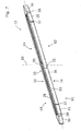
- the strip-shaped opener element 22 is shown in FIG. 7 in a perspective view. Further the strip-shaped opener element 22 together with the guide 21 is shown in different ways in FIGS. 8 to 11 .
- FIGS. 12 and 13 show the embodiments of FIGS. 3 and 4 in dismantled state.
- the strip-shaped opener element 22 is provided with an upper side 30, a lower side 31, a first lateral side 32 and an opposing second lateral side 33, wherein the first lateral side 32 and the second lateral side 33 extend between the upper side 30 and the lower side 31.
- the strip-shaped opener element 22 shown has two orthogonal lines of symmetry 82 and 83 diagrammatically indicated by broken lines in FIG. 7 .
- the strip-shaped opener element 22 has four operating surfaces 61, 62, 63, 64 and can be used in four different orientations.
- two operating surfaces of the opener element 22 are provided, more particularly two operating surfaces 61, 62 at the lateral side 32 and two operating surfaces 63, 64 at the lateral side 33.
- Each operating surface 61, 62, 63, 64 is adapted for cooperating with the gripper clamp of the gripper 2, 3 (shown in FIG. 2 ) for opening the gripper clamp of the gripper 2, 3.
- the operating surfaces 61, 62, 63, 64 are identical in design.
- the strip-shaped opener element 22 shown is provided at each lateral side 32, 33 with five surface parts 34, 35, 36 arranged at different angles with respect to a longitudinal direction and with four transition regions 37, 38 arranged between the surface parts 34, 35, 36.
- three surface parts 34, 35, 36 and the associated transition regions 37, 38 form an operating surface 61, 62; 63, 64, wherein a central surface part 34 is used by both operating surfaces 61, 62; 63, 64.
- a comparatively long straight central surface part 34 is provided.
- Such a central surface part 34 is advantageous for controlling an opening amount of the gripper clamp.
- surface parts 36 with a comparatively high angle of inclination are provided at the distal ends of the lateral side 32, 33.
- Such surface parts 36 are advantageous in order to open the gripper clamp quickly.
- surface parts 35 having a smaller angle of inclination than the surface parts 36 at the distal ends are provided, which is advantageous for stabilizing the movement of the gripper clamp during opening or closing.
- first coupling element 28 in the form of a groove is provided at the upper side 30 .
- second coupling element 79 (shown in FIG. 10 ), which is identical in construction to the first coupling element 28, hence, also in the form of a groove, is provided at the lower side 31 .
- the first coupling element 28 and the second coupling element 79 are arranged centrally in a direction perpendicular to the longitudinal direction at the upper side 30 and the lower side 31, respectively. Further, the first coupling element 28 and the second coupling element 79 are positioned in mirror symmetry to one another. Finally, the first coupling element 28 and the second coupling element 79 each have a plane of symmetry perpendicular to the upper side 30 and the lower side 31.
- a through hole 39 is provided for coupling the strip-shaped opener element 22 to the rod 25 shown in FIG. 8 .
- FIG. 9 is a top view of the guide 21 and the strip-shaped opener element 22.
- FIGS. 10 and 11 are cross sections along plane A-A and plane B-B in FIG. 9 , respectively.
- the guide 21 is provided with a counter element 27 in the form of a tongue protruding from an edge of the opening of the guiding channel 26 of the guide 21.
- the strip-shaped opener element 22 is mountable in the guiding channel 26 movably along the longitudinal direction of the guiding channel 26.
- the opener element 22 can present one of the four operating surfaces 61, 62, 63, 64 of the opener element 22 to contact the gripper clamp, for example for opening the gripper clamp 14 of the receiver gripper 3 shown in FIG. 5 .
- the first coupling element 28 this is the groove, provided on the upper side 30, or the second coupling element 79, this is the groove, provided on the lower side 31 is connected to the counter element 27, this is the tongue, provided at the guide 21 to form a tongue-and-groove connection for guiding the strip-shaped opener element 22 in the guiding channel 26 perpendicular to the longitudinal direction.
- the guide 21 comprises a main body 70 and a bottom element 71, which is detachable from the main body 70 for mounting and dismounting the strip-shaped opener element 22.
- the main body 70 and the bottom element 71 together form a U-shaped guiding channel 26.
- the counter element 27 is provided at the main body 70 at an edge of the opening of the guiding channel 26.
- a counter element 27 is provided at the bottom element 71, which is inserted in the groove provided at the coupling element 79 at a side of the strip-shaped opener element 22 facing the bottom element 71.
- the main body 70 is provided with a cut out 72 (shown in FIG. 9 ).
- the cut out 72 also separates the tongue provided as the counter element 27 at the main body 70 in two distinct tongue parts providing two distinct guiding areas 84 and 85 in the longitudinal direction of the guiding channel at two sides of the through hole 39.
- the guide 21 is provided with mounting blocks 86 having bores 42 for receiving pin-shaped elements 41 (shown in FIGS. 3 and 4 ).
- the guide 21 is arranged on a frame 60 of the weaving machine with the guiding channel 26 extending in parallel to a movement direction of the gripper 2, 3 (shown in FIG. 2 ).
- the gripper opener 20 comprises a support plate 29 attached using bolts 66 via a support block 47 to the frame 60.
- the guide 21 is fixeable to the frame 60 of the weaving machine via the support plate 29.
- the support plate 29 shown in FIGS. 3 and 4 is provided with two slotted holes 40, which are arranged at a slanted angle with respect to the longitudinal direction of the guiding channel 26.
- the guide 21 is fixed to the support plate 29 by means of two pin-shaped elements 41 each extending through one slotted hole 40 and are received in a bore 42 (shown in FIG. 6 ).
- the guide 21 is manually adjustable in position with respect to the support plate 29 in the movement direction of the gripper 2, 3 (shown in FIG. 2 ) and a transversal direction perpendicular to the movement direction of the gripper 2, 3 within the limits defined by the slotted holes 40.
- Both slotted holes 40 are arranged in parallel with respect to each other, hence, the longitudinal direction of the guiding channel 26 remains arranged in parallel to the movement direction of the gripper 2, 3 when adjusting a position of the guide 21.
- the guide 21 is fixed at the support plate 29 in a desired position.
- Butterfly nuts or wing nuts are provided at the pin-shaped elements 41 for fastening or loosening the pin-shaped elements 41.
- the butterfly nuts or wing nuts allow for a simple handling.
- the guide 21 and the strip-shaped opener element 22 are positioned underneath the support plate 29 between the frame 60 of the weaving machine and the support plate 29.
- the support plate 29 is provided with a removeable cover 43.
- the gripper opener 20 shown in FIGS. 3 and 4 further comprises a stop bar 44, which is arranged fixed in position on the frame 60 of the weaving machine.
- the stop bar 44 and the strip-shaped opener element 22 are arranged at the opposite sides of the movement path of the receiver gripper 3 (shown in FIG. 2 ), so that the receiver gripper 3 is guided sandwiched between the strip-shaped opener element 22 and the stop bar 44.
- the stop bar 44 limits an evasive movement of the receiver gripper 3 away from the strip-shaped opener element 22.
- a suction-unit 45 is provided.
- the suction-unit 45 is attached to the frame 60 in the region of the strip-shaped opener element 22.
- a blowing device 46 is provided to blow dust away from the gripper clamp.
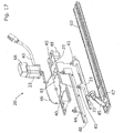
- FIGS. 14 and 15 are a perspective view of a second embodiment of a gripper opener 20, while FIGS. 16 and 17 show a dismantled state.
- the gripper opener 20 is similar to the gripper opener 20 shown in FIGS. 3 to 13 and the same reference numbers will be used for identical or like elements.
- the guide 21 is fixed to the support plate 29 by means of two pin-shaped elements 41 each extending through one associated slotted hole 40 provided at the support plate 29.
- the support plate 29 is attached to the frame 60 movable in position in the movement direction of the gripper 2, 3 (shown in FIG. 2 ).
- slotted holes 80, 81 are provided at the support plate 29 that extend after mounting the support plate 29 in parallel to the movement direction of the gripper 2, 3.
- a blowing device 46 can be provided on the support plate 29 in order to blow away dust from the gripper clamp.
- the suction-unit 45 is fixed via the support 67 to the frame 60 of the weaving machine. Hence, the suction-unit 45 is not moved with the support plate 29 when adjusting the position of the support plate 29.
- the support plate 29 is fixed via a support profile 48 to the frame 60.
- a stop bar 44 is fixed to the support profile 48, so that a gripper 2, 3 can be guided between the stop bar 44 and the strip-shaped opener element 22.
- the support plate 29 is also fixed to the frame 60 in a determined length position with respect to the frame 60 via at least one support block 49 and bolts 65.
- a gripper opener 20 is shown that cooperates with a gripper clamp 14 of the receiver gripper 3.
- the embodiments shown for the gripper opener 20 can of course also be applied for a gripper opener 5 that cooperates with a gripper clamp 14 of the bringer gripper 2.
Landscapes
- Engineering & Computer Science (AREA)
- Textile Engineering (AREA)
- Looms (AREA)
Description
- The invention relates to a gripper opener for opening a gripper clamp of a gripper in a weaving machine.
- A gripper opener for opening a gripper clamp of a gripper is disclosed for example in
EP 0 309 700 A1 - As described in
WO 97/40218 A1 WO 97/40218 A1 -
EP 1 491 670 A1 - It is an object of the invention to provide a gripper opener and a weaving machine having low manufacturing costs and low maintenance costs.
- This object is solved by the gripper opener with the features of
claim 1 and the gripper weaving machine with the features ofclaim 13. - According to a first aspect a gripper opener for opening a gripper clamp of a gripper in a weaving machine comprising a strip-shaped opener element and a guide with a guiding channel is provided, wherein the guide can be arranged on the weaving machine with the guiding channel extending in parallel to a movement direction of the gripper, wherein the strip-shaped opener element is provided with an upper side, a lower side, a first lateral side and a second lateral side, wherein the first lateral side and the second lateral side extend between the upper side and the lower side, wherein the strip-shaped opener element has a first operating surface provided at the first lateral side, wherein the first operating surface is adapted for cooperating with the gripper clamp for opening the gripper clamp, wherein the strip-shaped opener element is arrangeable in the guiding channel movably along the longitudinal direction of the guiding channel and presents the first operating surface of the opener element to make contact with the gripper clamp for opening the gripper clamp, wherein the strip-shaped opener element is provided at the upper side with a first coupling element and is provided at the lower side with a second coupling element, which is identical in construction to the first coupling element, wherein the first coupling element and the second coupling element are arranged centrally in a direction perpendicular to the longitudinal direction at the upper side and the lower side, respectively, and positioned in mirror symmetry to one another, wherein the guide is provided with at least one counter element, and wherein at least one of the first coupling element and the second coupling element forms a tongue-and-groove connection with the at least one counter element for guiding the strip-shaped opener element in the guiding channel perpendicular to the longitudinal direction.
- The tongue-and-groove connection allows for a reliable guidance of the strip-shaped opener element perpendicular to the longitudinal direction.
- Due to the contact with the gripper clamp to be opened, the first operating surface is subjected to wear. At the end of the life time of the first operating surface, the strip-shaped opener element can be flipped or turned and thereby brought into a different orientation and reused with a different orientation.
- For example, the strip-shaped opener element can be mounted in the first orientation in the guiding channel presenting the first operating surface. Due to the symmetric, central arrangement of the first coupling element and the second coupling element, the strip-shaped opener element can be dismounted, brought into a second orientation by rotating it by 180° about the longitudinal direction, a normal direction perpendicular to the upper side and/or a third axis perpendicular to the longitudinal direction and the normal direction, and re-mounted in the second orientation in the guide surface, wherein in each orientation one of the first coupling element and the second coupling element cooperates with the counter element.
- In one embodiment, only one counter element is provided. In other embodiments, two counter elements are provided at opposing sides of the guiding channel, which cooperate with the first coupling element and the second coupling element.
- A respective strip-shaped opener element can be manufactured at low costs. Further, as the strip-shaped opener element can be mounted and used with different orientations, the maintenance costs are low.
- In preferred embodiments, the strip-shaped opener element has four operating surfaces, wherein at each lateral side two operating surfaces are provided. With such a design, the strip-shaped opener element can be used four times, this is with four different orientations, wherein in each orientation one operating surface is presented and in each orientation at least one of the first coupling element or the second coupling element cooperates with the counter element of the guide.
- In one embodiment, the operating surfaces are different in design, wherein by choosing an orientation of the strip-shaped opener element with respect to the guide an opening profile of the gripper clamp is influenced.
- In preferred embodiments, the strip-shaped opener element has two orthogonal lines of symmetry. Hence, the operating surfaces are at least within tolerances identical in design and an orientation of the strip-shaped opener element with respect to the guide does not influence an opening profile of the gripper clamp.
- In one embodiment, the first coupling element and the second coupling element both are tongues, wherein corresponding grooves are provided at the guiding channel for receiving the tongues. In preferred embodiments, the first coupling element and the second coupling element are in the form of a groove each extending in the longitudinal direction, and the counter element is a tongue, in particular a tongue protruding from an edge of an opening of the guiding channel. In one embodiment, two tongues are provided protruding from opposing edges of the opening of the guiding channel. In one embodiment, the tongue extends uninterrupted over a distance allowing for a sufficient displacement of the strip-shaped opener element along the tongue.
- In preferred embodiments, the counter element comprises two distinct tongue parts for providing two distinct guiding areas in the longitudinal direction. Thereby, a reliable guidance is provided, while a risk of jamming or the like due to tolerances is minimized.
- In one embodiment, the strip-shaped opener element is manually positioned in the longitudinal direction for an adjustment of an opening position of a gripper clamp. In other embodiments, a hydraulic or a pneumatic drive is provided for positioning the strip-shaped opener element. In preferred embodiments, the gripper opener comprises a drive motor drivingly coupled to the strip-shaped opener element and operable to displace the strip-shaped opener element along the longitudinal direction. A coupling mechanism for coupling the drive motor and the strip-shaped opener element is chosen suitably by the person skilled in the art. In preferred embodiments, the drive motor is coupled to the strip-shaped opener element via a crank and a rod.
- In preferred embodiments, the gripper opener comprises a support plate, wherein the guide is fixable to a frame of the weaving machine via the support plate. The gripper and the support plate can be designed as a preassembled submodule allowing for a simple arrangement on the weaving machine.
- The guide in preferred embodiments is arranged on the support plate adjustable in position in at least one of the movement direction of the gripper and a transversal direction perpendicular to the movement direction of the gripper. By adjusting the position of the guide, an opening profile of a gripper clamp, in particular an opening amount, can be adapted to weaving conditions. In one embodiment, at least one drive mechanism is provided for adjusting a position of the guide on the support plate. In preferred embodiments, the guide is arranged on the support plate manually adjustable in position. This allows for a cost-efficient design by reducing the number of drive mechanisms.
- In preferred embodiments, the connection between the support plate and the guide comprises at least one slotted hole and a pin-shaped element extending through the slotted hole. The slotted hole allows for a reliable relative positioning of the support plate and the guide within limits. Preferably, the slotted hole is arranged at a slanted angle with respect to the longitudinal direction of the guiding channel.
- In one embodiment, the support plate carries only the gripper opener. In other embodiments, additional elements are arranged on the support plate. For example, in one embodiment, a suction-unit is mounted on the frame of the weaving machine. The suction-unit in one embodiment is used to remove dust and/or to keep taut ends of weft threads that are released by the receiving gripper, so that these ends would not bound back into the warp threads.
- In one embodiment, when mounted to a weaving machine the guide and the strip-shaped opener element are positioned underneath the support plate between the frame of the weaving machine and the support plate.
- In this case, in preferred embodiments, the support plate is provided with a removeable cover for allowing access to the guide and/or the strip-shaped opener element positioned underneath the support plate.
- In preferred embodiments, a stop bar is provided that can be arranged fixed in position on the weaving machine, so that the gripper is guided sandwiched between the guide with the strip-shaped opener element and the stop bar. By means of the stop bar, an unintended evasive movement of the gripper clamp in contact with the strip-shaped opener element is avoided.
- According to a second aspect, a weaving machine comprising a gripper with a gripper clamp and a gripper opener as described above is provided.
- Further characteristics and advantages of the invention will emerge from the following description of the embodiments schematically illustrated in the drawings. Throughout the drawings, the same elements will be denoted by the same reference numerals.
-
FIG. 1 is a perspective view of a gripper weaving machine. -
FIG. 2 is a view in the direction of the arrow II ofFIG. 1 . -
FIG. 3 is a perspective view of the gripper opener from the back, this means towards the fabric. -
FIG. 4 is a perspective view of a gripper opener ofFIG. 3 from the front, this means away from the fabric. -
FIG. 5 is a schematic view of a receiver gripper. -
FIG. 6 is a perspective view of parts of a second embodiment of a gripper opener. -
FIG. 7 is a perspective view of a strip-shaped opener element of a gripper opener according to the invention. -
FIG. 8 is a sectional view of the strip-shaped opener element ofFIG. 6 . -
FIG. 9 is a top view of a part ofFIG. 6 . -
FIG. 10 is a cross section along plane A-A inFIG. 9 . -
FIG. 11 is a cross section along plane B-B inFIG. 9 . -
FIG. 12 is the embodiment ofFIG. 3 in dismantled state. -
FIG. 13 is the embodiment ofFIG. 4 in dismantled state. -
FIG. 14 is a perspective view of a third embodiment of a gripper opener from the back side. -
FIG. 15 is a perspective view of the gripper opener ofFIG. 14 from the front side. -
FIG. 16 is the embodiment ofFIG. 14 in dismantled state. -
FIG. 17 is the embodiment ofFIG. 15 in dismantled state. - The weaving machine shown in
FIGS. 1 and 2 comprises tworapiers 1, each bearing at its free end agripper gripper 2 is further named bringer gripper and thegripper 3 is further named receiver gripper. At the insertion side of a shed formed ofwarp threads 12, thebringer gripper 2 receives a weft thread 4 which is presented to thebringer gripper 2 by a presentingdevice 19. A weft thread supply is stored on aspool 17 from which a weft thread 4 to be inserted is to be removed and wound on a prewinder 18 before being inserted into the shed. Usually, there areseveral spools 17 and several prewinders 18 from which the weft threads are presented in a pre-selectable pattern by the presentingdevice 19 to thebringer gripper 2. - The
rapiers 1 are driven bydrive wheels 6 and are guided around thesedrive wheels 6 byguides 7. Therapiers 1 move into and out again from the shed and as a result thebringer gripper 2 and thereceiver gripper 3 meet centrally in the shed. Thereupon thereceiver gripper 3 receives the weft thread 4 and pulls the weft thread 4 to the opposite side, this is the side opposite to the insertion side. Next the inserted weft thread is beaten-up by areed 11 against thefabric 13. Thereed 11 is mounted on asley 10 and moves in reciprocating manner. - In order to form a shed, the
warp threads 12 are selectively raised and lowered by means of so-called healds 9. The shed is changed after the weft thread 4 has been inserted. - When the
bringer gripper 2 receives a weft thread 4 presented to it, a gripper clamp mounted on thebringer gripper 2 is closed. Similar, thereceiver gripper 3 also is provided with a gripper clamp holding the weft thread 4 during transport, which is opened when thereceiver gripper 3 has reached the opposite side. Closing the gripper clamp of thebringer gripper 2 when receiving a weft thread 4 and when entering the shed is controlled by agripper opener 5. Opening the gripper clamp of thereceiver gripper 3 in the region outside the shed on the opposite side is controlled by agripper opener 20. - The
gripper openers FIG. 3 ) having an operating surface adapted to contact the gripper clamp for opening the gripper clamp. Depending on the design of the gripper clamp of thegripper gripper opener opener element 22 located away from thefabric 13 with respect to the movement path of thegripper opener element 22 located towards thefabric 13 with respect to the movement path of thegripper opener element 22 makes contact with the gripper clamp. -
FIGS. 3 and4 show diagrammatically agripper opener 20 arranged on the opposite side and comprising a strip-shapedopener element 22 arranged away from afabric 13 with respect to the movement path of thereceiver gripper 3. In an embodiment, as known inWO 02/077343 FIG. 5 , thereceiver gripper 3 comprises amoveable gripper clamp 14 with a protrudingcontact element 15 that can cooperate with theopener element 22 of thegripper opener 20 in order to open or close thegripper clamp 14 of thereceiver gripper 3. The protrudingcontact element 15 is, for example, provided at a lever that is part of thegripper clamp 14. - The
gripper opener 20 comprises aguide 21 with a guidingchannel 26, which is arranged on the weaving machine so that the guidingchannel 26 extends in parallel to the movement direction of thegripper opener element 22 is mounted in the guidingchannel 26 presenting afirst operating surface 61, which first operatingsurface 61 is adapted for cooperating with thegripper clamp 14 of thereceiver gripper 3, more particular the protruding contact element 15 (shown inFIG. 5 ) for opening thegripper clamp 14 of thereceiver gripper 3. The strip-shapedopener element 22 is received in the guidingchannel 26 movably along the longitudinal direction of the guidingchannel 26, wherein theopener element 22 is movable along the longitudinal direction for an adjustment of an opening position for the gripper clamp. In order to move the strip-shapedopener element 22, in the embodiment shown inFIGS. 3 and4 adrive motor 23 is provided. As shown in more detail inFIG. 6 thedrive motor 23 is coupled to the strip-shapedopener element 22 via a crank 24 and arod 25. Anencoder 68 can be provided at thedrive motor 23 to determine the angular position of thedrive motor 23. Thedrive motor 23 and/or theencoder 68 are coupled to a control unit (not shown) via anelectric cable 69. - The
guide 21, the strip-shapedopener element 22, thedrive motor 23 and thecoupling mechanism 16 comprising thecrank 24 and therod 25 are shown inFIG. 6 . The strip-shapedopener element 22 is shown inFIG. 7 in a perspective view. Further the strip-shapedopener element 22 together with theguide 21 is shown in different ways inFIGS. 8 to 11 .FIGS. 12 and13 show the embodiments ofFIGS. 3 and4 in dismantled state. - As can be best seen in
FIG. 7 , the strip-shapedopener element 22 is provided with anupper side 30, alower side 31, a firstlateral side 32 and an opposing secondlateral side 33, wherein the firstlateral side 32 and the secondlateral side 33 extend between theupper side 30 and thelower side 31. - The strip-shaped
opener element 22 shown has two orthogonal lines ofsymmetry FIG. 7 . - The strip-shaped
opener element 22 has four operatingsurfaces lateral side opener element 22 are provided, more particularly two operatingsurfaces lateral side 32 and two operatingsurfaces lateral side 33. Each operatingsurface gripper 2, 3 (shown inFIG. 2 ) for opening the gripper clamp of thegripper opener element 22 shown is provided at eachlateral side surface parts transition regions surface parts surface parts transition regions surface central surface part 34 is used by both operatingsurfaces - In the embodiment shown, a comparatively long straight
central surface part 34 is provided. Such acentral surface part 34 is advantageous for controlling an opening amount of the gripper clamp. In addition, at the distal ends of thelateral side surface parts 36 with a comparatively high angle of inclination are provided.Such surface parts 36 are advantageous in order to open the gripper clamp quickly. Between the straightcentral surface part 34 and thesurface parts 36 at the distal ends, in the embodiment shownsurface parts 35 having a smaller angle of inclination than thesurface parts 36 at the distal ends are provided, which is advantageous for stabilizing the movement of the gripper clamp during opening or closing. - At the upper side 30 a
first coupling element 28 in the form of a groove is provided. At the lower side 31 a second coupling element 79 (shown inFIG. 10 ), which is identical in construction to thefirst coupling element 28, hence, also in the form of a groove, is provided. Thefirst coupling element 28 and thesecond coupling element 79 are arranged centrally in a direction perpendicular to the longitudinal direction at theupper side 30 and thelower side 31, respectively. Further, thefirst coupling element 28 and thesecond coupling element 79 are positioned in mirror symmetry to one another. Finally, thefirst coupling element 28 and thesecond coupling element 79 each have a plane of symmetry perpendicular to theupper side 30 and thelower side 31. - At a center of the strip-shaped
opener element 22, a throughhole 39 is provided for coupling the strip-shapedopener element 22 to therod 25 shown inFIG. 8 . -
FIG. 9 is a top view of theguide 21 and the strip-shapedopener element 22.FIGS. 10 and 11 are cross sections along plane A-A and plane B-B inFIG. 9 , respectively. As shown inFIGS. 10 and 11 , theguide 21 is provided with acounter element 27 in the form of a tongue protruding from an edge of the opening of the guidingchannel 26 of theguide 21. The strip-shapedopener element 22 is mountable in the guidingchannel 26 movably along the longitudinal direction of the guidingchannel 26. Hereby theopener element 22 can present one of the four operatingsurfaces opener element 22 to contact the gripper clamp, for example for opening thegripper clamp 14 of thereceiver gripper 3 shown inFIG. 5 . Depending on the orientation of the strip-shapedopener element 22, thefirst coupling element 28, this is the groove, provided on theupper side 30, or thesecond coupling element 79, this is the groove, provided on thelower side 31 is connected to thecounter element 27, this is the tongue, provided at theguide 21 to form a tongue-and-groove connection for guiding the strip-shapedopener element 22 in the guidingchannel 26 perpendicular to the longitudinal direction. - In the embodiment shown, the
guide 21 comprises amain body 70 and abottom element 71, which is detachable from themain body 70 for mounting and dismounting the strip-shapedopener element 22. Themain body 70 and thebottom element 71 together form aU-shaped guiding channel 26. As can be seen inFIGS. 10 and 11 , thecounter element 27 is provided at themain body 70 at an edge of the opening of the guidingchannel 26. In alternative or in addition, acounter element 27 is provided at thebottom element 71, which is inserted in the groove provided at thecoupling element 79 at a side of the strip-shapedopener element 22 facing thebottom element 71. - In order to avoid interference with the
rod 25, themain body 70 is provided with a cut out 72 (shown inFIG. 9 ). The cut out 72 also separates the tongue provided as thecounter element 27 at themain body 70 in two distinct tongue parts providing twodistinct guiding areas hole 39. - As can be best seen in
FIG. 6 , theguide 21 is provided with mountingblocks 86 havingbores 42 for receiving pin-shaped elements 41 (shown inFIGS. 3 and4 ). - As shown in
FIGS. 3 and4 , theguide 21 is arranged on aframe 60 of the weaving machine with the guidingchannel 26 extending in parallel to a movement direction of thegripper 2, 3 (shown inFIG. 2 ). In the embodiment shown, thegripper opener 20 comprises asupport plate 29 attached usingbolts 66 via asupport block 47 to theframe 60. Theguide 21 is fixeable to theframe 60 of the weaving machine via thesupport plate 29. - The
support plate 29 shown inFIGS. 3 and4 is provided with two slottedholes 40, which are arranged at a slanted angle with respect to the longitudinal direction of the guidingchannel 26. Theguide 21 is fixed to thesupport plate 29 by means of two pin-shapedelements 41 each extending through one slottedhole 40 and are received in a bore 42 (shown inFIG. 6 ). Theguide 21 is manually adjustable in position with respect to thesupport plate 29 in the movement direction of thegripper 2, 3 (shown inFIG. 2 ) and a transversal direction perpendicular to the movement direction of thegripper holes 40 are arranged in parallel with respect to each other, hence, the longitudinal direction of the guidingchannel 26 remains arranged in parallel to the movement direction of thegripper guide 21. By fastening the pin-shapedelements 41 theguide 21 is fixed at thesupport plate 29 in a desired position. Butterfly nuts or wing nuts are provided at the pin-shapedelements 41 for fastening or loosening the pin-shapedelements 41. The butterfly nuts or wing nuts allow for a simple handling. - As best can be seen in
FIGS. 3 and4 , in the shown embodiment, theguide 21 and the strip-shapedopener element 22 are positioned underneath thesupport plate 29 between theframe 60 of the weaving machine and thesupport plate 29. In order to allow an operator access to elements that are positioned underneath thesupport plate 29, such as theguide 21, the strip-shapedopener element 22 and/or arod 25, without the necessity of dismounting theguide 21 from thesupport plate 29, thesupport plate 29 is provided with aremoveable cover 43. - The
gripper opener 20 shown inFIGS. 3 and4 further comprises astop bar 44, which is arranged fixed in position on theframe 60 of the weaving machine. Thestop bar 44 and the strip-shapedopener element 22 are arranged at the opposite sides of the movement path of the receiver gripper 3 (shown inFIG. 2 ), so that thereceiver gripper 3 is guided sandwiched between the strip-shapedopener element 22 and thestop bar 44. Thestop bar 44 limits an evasive movement of thereceiver gripper 3 away from the strip-shapedopener element 22. - In the embodiment shown in
FIGS. 3 and4 , further a suction-unit 45 is provided. The suction-unit 45 is attached to theframe 60 in the region of the strip-shapedopener element 22. Further ablowing device 46 is provided to blow dust away from the gripper clamp. -
FIGS. 14 and15 are a perspective view of a second embodiment of agripper opener 20, whileFIGS. 16 and17 show a dismantled state. Thegripper opener 20 is similar to thegripper opener 20 shown inFIGS. 3 to 13 and the same reference numbers will be used for identical or like elements. This allows the strip-shapedopener element 22, which is driven by thedrive motor 23 for a displacement along the longitudinal direction of a guidingchannel 26, to be arranged on theframe 60 in the direction towards the shed formed of warp threads 12 (shown inFIG. 1 ) or away from thefabric 13. - The
guide 21 is fixed to thesupport plate 29 by means of two pin-shapedelements 41 each extending through one associated slottedhole 40 provided at thesupport plate 29. Thesupport plate 29 is attached to theframe 60 movable in position in the movement direction of thegripper 2, 3 (shown inFIG. 2 ). For this purpose, slottedholes support plate 29 that extend after mounting thesupport plate 29 in parallel to the movement direction of thegripper device 46 can be provided on thesupport plate 29 in order to blow away dust from the gripper clamp. - In
FIGS. 14 to 17 , the suction-unit 45 is fixed via thesupport 67 to theframe 60 of the weaving machine. Hence, the suction-unit 45 is not moved with thesupport plate 29 when adjusting the position of thesupport plate 29. Thesupport plate 29 is fixed via asupport profile 48 to theframe 60. Astop bar 44 is fixed to thesupport profile 48, so that agripper stop bar 44 and the strip-shapedopener element 22. Thesupport plate 29 is also fixed to theframe 60 in a determined length position with respect to theframe 60 via at least onesupport block 49 andbolts 65. - In the embodiment shown in
FIGS. 3 to 17 agripper opener 20 is shown that cooperates with agripper clamp 14 of thereceiver gripper 3. The embodiments shown for thegripper opener 20 can of course also be applied for agripper opener 5 that cooperates with agripper clamp 14 of thebringer gripper 2. - The invention is not limited to the embodiments described by way of example and illustrated in the drawings. Variant embodiments concerning shapes and dimensions that fall under the claims and combinations of the described and illustrated embodiments are also possible.
Claims (15)
- A gripper opener for opening a gripper clamp (14) of a gripper (2, 3) of a weaving machine comprising a strip-shaped opener element (22) and a guide (21) with a guiding channel (26), wherein the guide (21) can be arranged on the weaving machine with the guiding channel (26) extending in parallel to a movement direction of the gripper (2, 3), wherein the strip-shaped opener element (22) is provided with an upper side (30), a lower side (31), a first lateral side (32) and a second lateral side (33), wherein the first lateral side (32) and the second lateral side (33) extend between the upper side (30) and the lower side (31), wherein the strip-shaped opener element (22) has a first operating surface (61) provided at the first lateral side (32), wherein the first operating surface (61) is adapted for cooperating with the gripper clamp (14) for opening the gripper clamp (14), and wherein the strip-shaped opener element (22) is arrangeable in the guiding channel (26) movably along the longitudinal direction of the guiding channel (26) and presents the first operating surface (61) of the opener element (22) to make contact with the gripper clamp (14) for opening the gripper clamp (14), characterized in that the strip-shaped opener element (22) is provided at the upper side (30) with a first coupling element (28) and is provided at the lower side (31) with a second coupling element (79), which is identical in construction to the first coupling element (28), wherein the first coupling element (28) and the second coupling element (79) are arranged centrally in a direction perpendicular to the longitudinal direction at the upper side (30) and the lower side (31), respectively, and positioned in mirror symmetry to one another, wherein the guide (21) is provided with at least one counter element (27), and wherein one of the first coupling element (28) and the second coupling element (79) forms a tongue-and-groove connection with the at least one counter element (27) for guiding the strip-shaped opener element (22) in the guiding channel (26) perpendicular to the longitudinal direction.
- The gripper opener according to claim 1, characterized in that the strip-shaped opener element (22) has four operating surfaces (61, 62, 63, 64), wherein at each lateral side (32, 33) two operating surfaces are provided.
- The gripper opener according to claim 1 or 2, characterized in that the strip-shaped opener element (22) has two orthogonal lines of symmetry (82, 83).
- The gripper opener according to claim 1, 2 or 3, characterized in that the first coupling element (28) and the second coupling element (79) each are in the form of a groove extending in the longitudinal direction, and the counter element (27) is a tongue, in particular a tongue protruding from an edge of an opening of the guiding channel (26).
- The gripper opener according to claim 4, characterized in that the counter element (27) comprises two distinct tongue parts for providing two distinct guiding areas (84, 85) in the longitudinal direction.
- The gripper opener according to any one of claims 1 to 5, characterized in that the gripper opener (5, 20) comprises a drive motor (23) drivingly coupled to the strip-shaped opener element (22) and operable to displace the strip-shaped opener element (22) along longitudinal direction, wherein in particular the drive motor (23) is coupled to the strip-shaped opener element (22) via a crank (24) and a rod (25).
- The gripper opener according to any one of claims 1 to 6, characterized in that the gripper opener (20) comprises a support plate (29), wherein the guide (21) is fixable to a frame (60) of the weaving machine via the support plate (29).
- The gripper opener according to claim 7, characterized in that the guide (21) is arranged on the support plate (29) adjustable in position in at least one of the movement direction of the gripper (2, 3) and a transversal direction perpendicular to a movement direction of the gripper (2, 3), wherein in particular the guide (21) is arranged on the support plate (29) manually adjustable in position.
- The gripper opener according to claim 8, characterized in that the connection between the support plate (29) and the guide (21) comprises at least one slotted hole (40) and a pin-shaped element (41) extending through the slotted hole (40).
- The gripper opener according to claim 9, characterized in that the slotted hole (40) is arranged at a slanted angle with respect to the longitudinal direction of the guiding channel (26).
- The gripper opener according to any one of claims 7 to 10, characterized in that when mounted to a weaving machine the guide (21) and the strip-shaped opener element (22) are positioned underneath the support plate (29) between the frame (60) of the weaving machine and the support plate (29).
- The gripper opener according to claim 11, characterized in that the support plate (29) is provided with a removeable cover (43) for allowing access to the guide (21) and/or the strip-shaped opener element (22) positioned underneath the support plate (29).
- A weaving machine comprising a gripper (2, 3) with a gripper clamp (14) and a gripper opener (5, 20) according to any one of claims 1 to 12.
- The weaving machine according to claim 13, characterized in that a suction-unit (45) is mounted on the frame (60) of the weaving machine.
- The weaving machine according to any one of claims 13 or 14, characterized in that a stop bar (44) is provided that can be arranged fixed in position on the weaving machine, so that the gripper (2, 3) is guided sandwiched between the guide (21) with the strip-shaped opener element (22) and the stop bar (44).
Applications Claiming Priority (2)
| Application Number | Priority Date | Filing Date | Title |
|---|---|---|---|
| BE20150142A BE1023036A1 (en) | 2015-05-07 | 2015-05-07 | GRIPPER OPERATOR FOR A WEAVING MACHINE |
| PCT/EP2016/059247 WO2016177601A1 (en) | 2015-05-07 | 2016-04-26 | Gripper opener for a weaving machine |
Publications (2)
| Publication Number | Publication Date |
|---|---|
| EP3292235A1 EP3292235A1 (en) | 2018-03-14 |
| EP3292235B1 true EP3292235B1 (en) | 2019-06-05 |
Family
ID=54014445
Family Applications (1)
| Application Number | Title | Priority Date | Filing Date |
|---|---|---|---|
| EP16722083.9A Active EP3292235B1 (en) | 2015-05-07 | 2016-04-26 | Gripper opener for a weaving machine |
Country Status (4)
| Country | Link |
|---|---|
| EP (1) | EP3292235B1 (en) |
| CN (1) | CN107580638B (en) |
| BE (1) | BE1023036A1 (en) |
| WO (1) | WO2016177601A1 (en) |
Families Citing this family (1)
| Publication number | Priority date | Publication date | Assignee | Title |
|---|---|---|---|---|
| EP4008818B1 (en) * | 2020-12-07 | 2024-07-17 | Picanol | Method for adjusting a gripper movement stroke and drive mechanism for moving a gripper |
Family Cites Families (6)
| Publication number | Priority date | Publication date | Assignee | Title |
|---|---|---|---|---|
| DE3812966A1 (en) | 1987-10-02 | 1989-04-20 | Textilma Ag | GRIPPER WEAVING MACHINE |
| WO1997040218A1 (en) * | 1996-04-19 | 1997-10-30 | Picanol N.V. | Device for opening a gripper clip of a mechanical loom gripper |
| DE10114755A1 (en) | 2001-03-21 | 2002-09-26 | Picanol Nv | Gripper clip for gripper loom, has pivoted gripper finger with guide surfaces at its end to restrain transverse motion |
| ITMI20030293U1 (en) | 2003-06-26 | 2004-12-27 | Promatech Spa | PERFECTED MOTORIZED OPENER |
| BE1018116A3 (en) * | 2008-05-07 | 2010-05-04 | Picanol Nv | TAKE-UP MEASURER, MEASURING MEASURE AND DEVICE FOR A GRIJPER-WOVEN MACHINE. |
| CN102978790A (en) * | 2012-10-26 | 2013-03-20 | 苏州市德明纺织机械配件有限公司 | Weft conveying opener |
-
2015
- 2015-05-07 BE BE20150142A patent/BE1023036A1/en not_active IP Right Cessation
-
2016
- 2016-04-26 EP EP16722083.9A patent/EP3292235B1/en active Active
- 2016-04-26 WO PCT/EP2016/059247 patent/WO2016177601A1/en not_active Ceased
- 2016-04-26 CN CN201680026539.1A patent/CN107580638B/en active Active
Non-Patent Citations (1)
| Title |
|---|
| None * |
Also Published As
| Publication number | Publication date |
|---|---|
| CN107580638B (en) | 2020-02-18 |
| EP3292235A1 (en) | 2018-03-14 |
| CN107580638A (en) | 2018-01-12 |
| WO2016177601A1 (en) | 2016-11-10 |
| BE1023036A1 (en) | 2016-11-09 |
Similar Documents
| Publication | Publication Date | Title |
|---|---|---|
| EP2449158B1 (en) | Device and method for catching and stretching weft threads in weaving machines | |
| US20180291538A1 (en) | Weaving Machine with an Apparatus as well as Method for Holding, Feeding and Inserting Weft Threads in a Loom Shed | |
| WO2016177601A1 (en) | Gripper opener for a weaving machine | |
| JP7017991B2 (en) | Weft operation device without pseudo selvage in gripper loom | |
| EP2732086B1 (en) | Device and method for clamping a weft thread | |
| KR20000005448A (en) | Device for opening a gripper clip of a mechanical loom gripper | |
| EP0309700B1 (en) | Gripper loom | |
| US5092374A (en) | Guide and support devices for weft inserters in shuttleless looms | |
| CN102471957B (en) | Gripper head of a weaving machine | |
| WO2007137544A1 (en) | Method and apparatus for forming a selvedge on a gripper weaving machine | |
| DE3224708C2 (en) | Device for the inevitable actuation of the clamping device of weft thread insertion organs on shuttleless looms | |
| BE1023036B1 (en) | GRIPPER OPERATOR FOR A WEAVING MACHINE | |
| US3951179A (en) | Device for severing a thread in a textile machine | |
| CN1871387B (en) | Device for selecting and feeding weft yarns to a gripper of a rapier weaving machine | |
| DE10349645A1 (en) | Method for selecting and delivering weft threads and rapier loom with a device for selecting and delivering weft threads | |
| EP3155155B1 (en) | Selvedge forming device for a weft thread | |
| EP4172393B1 (en) | Rapier weaving machine with guiding device and method for converting a rapier weaving machine | |
| DE1535249B1 (en) | TECHNICAL DEVICE FOR WEAVING MACHINES | |
| EP2184389B1 (en) | Weft insertion method and weft insertion device of rapier loom | |
| EP1927691B1 (en) | Weft holding device and method for a rapier weaving machine | |
| EP3507404B1 (en) | Device and method for catching and stretching weft threads | |
| DD243304B1 (en) | DEVICE FOR SHEET POSITIONING ON GRIPPER WEAVING MACHINES | |
| EP3433403B1 (en) | Gripper for a gripper weaving machine | |
| DE1535249C (en) | Shedding device for looms | |
| JP2016040424A (en) | Weft control device for air jet loom |
Legal Events
| Date | Code | Title | Description |
|---|---|---|---|
| STAA | Information on the status of an ep patent application or granted ep patent |
Free format text: STATUS: THE INTERNATIONAL PUBLICATION HAS BEEN MADE |
|
| PUAI | Public reference made under article 153(3) epc to a published international application that has entered the european phase |
Free format text: ORIGINAL CODE: 0009012 |
|
| STAA | Information on the status of an ep patent application or granted ep patent |
Free format text: STATUS: REQUEST FOR EXAMINATION WAS MADE |
|
| 17P | Request for examination filed |
Effective date: 20171107 |
|
| AK | Designated contracting states |
Kind code of ref document: A1 Designated state(s): AL AT BE BG CH CY CZ DE DK EE ES FI FR GB GR HR HU IE IS IT LI LT LU LV MC MK MT NL NO PL PT RO RS SE SI SK SM TR |
|
| AX | Request for extension of the european patent |
Extension state: BA ME |
|
| DAV | Request for validation of the european patent (deleted) | ||
| DAX | Request for extension of the european patent (deleted) | ||
| GRAP | Despatch of communication of intention to grant a patent |
Free format text: ORIGINAL CODE: EPIDOSNIGR1 |
|
| STAA | Information on the status of an ep patent application or granted ep patent |
Free format text: STATUS: GRANT OF PATENT IS INTENDED |
|
| INTG | Intention to grant announced |
Effective date: 20190129 |
|
| GRAS | Grant fee paid |
Free format text: ORIGINAL CODE: EPIDOSNIGR3 |
|
| GRAA | (expected) grant |
Free format text: ORIGINAL CODE: 0009210 |
|
| STAA | Information on the status of an ep patent application or granted ep patent |
Free format text: STATUS: THE PATENT HAS BEEN GRANTED |
|
| AK | Designated contracting states |
Kind code of ref document: B1 Designated state(s): AL AT BE BG CH CY CZ DE DK EE ES FI FR GB GR HR HU IE IS IT LI LT LU LV MC MK MT NL NO PL PT RO RS SE SI SK SM TR |
|
| REG | Reference to a national code |
Ref country code: GB Ref legal event code: FG4D |
|
| REG | Reference to a national code |
Ref country code: CH Ref legal event code: EP |
|
| REG | Reference to a national code |
Ref country code: AT Ref legal event code: REF Ref document number: 1140065 Country of ref document: AT Kind code of ref document: T Effective date: 20190615 |
|
| REG | Reference to a national code |
Ref country code: IE Ref legal event code: FG4D |
|
| REG | Reference to a national code |
Ref country code: DE Ref legal event code: R096 Ref document number: 602016014829 Country of ref document: DE |
|
| REG | Reference to a national code |
Ref country code: NL Ref legal event code: MP Effective date: 20190605 |
|
| REG | Reference to a national code |
Ref country code: LT Ref legal event code: MG4D |
|
| PG25 | Lapsed in a contracting state [announced via postgrant information from national office to epo] |
Ref country code: FI Free format text: LAPSE BECAUSE OF FAILURE TO SUBMIT A TRANSLATION OF THE DESCRIPTION OR TO PAY THE FEE WITHIN THE PRESCRIBED TIME-LIMIT Effective date: 20190605 Ref country code: AL Free format text: LAPSE BECAUSE OF FAILURE TO SUBMIT A TRANSLATION OF THE DESCRIPTION OR TO PAY THE FEE WITHIN THE PRESCRIBED TIME-LIMIT Effective date: 20190605 Ref country code: NO Free format text: LAPSE BECAUSE OF FAILURE TO SUBMIT A TRANSLATION OF THE DESCRIPTION OR TO PAY THE FEE WITHIN THE PRESCRIBED TIME-LIMIT Effective date: 20190905 Ref country code: HR Free format text: LAPSE BECAUSE OF FAILURE TO SUBMIT A TRANSLATION OF THE DESCRIPTION OR TO PAY THE FEE WITHIN THE PRESCRIBED TIME-LIMIT Effective date: 20190605 Ref country code: SE Free format text: LAPSE BECAUSE OF FAILURE TO SUBMIT A TRANSLATION OF THE DESCRIPTION OR TO PAY THE FEE WITHIN THE PRESCRIBED TIME-LIMIT Effective date: 20190605 Ref country code: LT Free format text: LAPSE BECAUSE OF FAILURE TO SUBMIT A TRANSLATION OF THE DESCRIPTION OR TO PAY THE FEE WITHIN THE PRESCRIBED TIME-LIMIT Effective date: 20190605 Ref country code: ES Free format text: LAPSE BECAUSE OF FAILURE TO SUBMIT A TRANSLATION OF THE DESCRIPTION OR TO PAY THE FEE WITHIN THE PRESCRIBED TIME-LIMIT Effective date: 20190605 |
|
| PG25 | Lapsed in a contracting state [announced via postgrant information from national office to epo] |
Ref country code: LV Free format text: LAPSE BECAUSE OF FAILURE TO SUBMIT A TRANSLATION OF THE DESCRIPTION OR TO PAY THE FEE WITHIN THE PRESCRIBED TIME-LIMIT Effective date: 20190605 Ref country code: BG Free format text: LAPSE BECAUSE OF FAILURE TO SUBMIT A TRANSLATION OF THE DESCRIPTION OR TO PAY THE FEE WITHIN THE PRESCRIBED TIME-LIMIT Effective date: 20190905 Ref country code: RS Free format text: LAPSE BECAUSE OF FAILURE TO SUBMIT A TRANSLATION OF THE DESCRIPTION OR TO PAY THE FEE WITHIN THE PRESCRIBED TIME-LIMIT Effective date: 20190605 Ref country code: GR Free format text: LAPSE BECAUSE OF FAILURE TO SUBMIT A TRANSLATION OF THE DESCRIPTION OR TO PAY THE FEE WITHIN THE PRESCRIBED TIME-LIMIT Effective date: 20190906 |
|
| REG | Reference to a national code |
Ref country code: AT Ref legal event code: MK05 Ref document number: 1140065 Country of ref document: AT Kind code of ref document: T Effective date: 20190605 |
|
| PG25 | Lapsed in a contracting state [announced via postgrant information from national office to epo] |
Ref country code: PT Free format text: LAPSE BECAUSE OF FAILURE TO SUBMIT A TRANSLATION OF THE DESCRIPTION OR TO PAY THE FEE WITHIN THE PRESCRIBED TIME-LIMIT Effective date: 20191007 Ref country code: SK Free format text: LAPSE BECAUSE OF FAILURE TO SUBMIT A TRANSLATION OF THE DESCRIPTION OR TO PAY THE FEE WITHIN THE PRESCRIBED TIME-LIMIT Effective date: 20190605 Ref country code: EE Free format text: LAPSE BECAUSE OF FAILURE TO SUBMIT A TRANSLATION OF THE DESCRIPTION OR TO PAY THE FEE WITHIN THE PRESCRIBED TIME-LIMIT Effective date: 20190605 Ref country code: AT Free format text: LAPSE BECAUSE OF FAILURE TO SUBMIT A TRANSLATION OF THE DESCRIPTION OR TO PAY THE FEE WITHIN THE PRESCRIBED TIME-LIMIT Effective date: 20190605 Ref country code: RO Free format text: LAPSE BECAUSE OF FAILURE TO SUBMIT A TRANSLATION OF THE DESCRIPTION OR TO PAY THE FEE WITHIN THE PRESCRIBED TIME-LIMIT Effective date: 20190605 Ref country code: CZ Free format text: LAPSE BECAUSE OF FAILURE TO SUBMIT A TRANSLATION OF THE DESCRIPTION OR TO PAY THE FEE WITHIN THE PRESCRIBED TIME-LIMIT Effective date: 20190605 Ref country code: NL Free format text: LAPSE BECAUSE OF FAILURE TO SUBMIT A TRANSLATION OF THE DESCRIPTION OR TO PAY THE FEE WITHIN THE PRESCRIBED TIME-LIMIT Effective date: 20190605 |
|
| PG25 | Lapsed in a contracting state [announced via postgrant information from national office to epo] |
Ref country code: IS Free format text: LAPSE BECAUSE OF FAILURE TO SUBMIT A TRANSLATION OF THE DESCRIPTION OR TO PAY THE FEE WITHIN THE PRESCRIBED TIME-LIMIT Effective date: 20191005 Ref country code: SM Free format text: LAPSE BECAUSE OF FAILURE TO SUBMIT A TRANSLATION OF THE DESCRIPTION OR TO PAY THE FEE WITHIN THE PRESCRIBED TIME-LIMIT Effective date: 20190605 |
|
| REG | Reference to a national code |
Ref country code: DE Ref legal event code: R097 Ref document number: 602016014829 Country of ref document: DE |
|
| PLBE | No opposition filed within time limit |
Free format text: ORIGINAL CODE: 0009261 |
|
| STAA | Information on the status of an ep patent application or granted ep patent |
Free format text: STATUS: NO OPPOSITION FILED WITHIN TIME LIMIT |
|
| PG25 | Lapsed in a contracting state [announced via postgrant information from national office to epo] |
Ref country code: PL Free format text: LAPSE BECAUSE OF FAILURE TO SUBMIT A TRANSLATION OF THE DESCRIPTION OR TO PAY THE FEE WITHIN THE PRESCRIBED TIME-LIMIT Effective date: 20190605 Ref country code: DK Free format text: LAPSE BECAUSE OF FAILURE TO SUBMIT A TRANSLATION OF THE DESCRIPTION OR TO PAY THE FEE WITHIN THE PRESCRIBED TIME-LIMIT Effective date: 20190605 |
|
| 26N | No opposition filed |
Effective date: 20200306 |
|
| PG25 | Lapsed in a contracting state [announced via postgrant information from national office to epo] |
Ref country code: SI Free format text: LAPSE BECAUSE OF FAILURE TO SUBMIT A TRANSLATION OF THE DESCRIPTION OR TO PAY THE FEE WITHIN THE PRESCRIBED TIME-LIMIT Effective date: 20190605 |
|
| PG25 | Lapsed in a contracting state [announced via postgrant information from national office to epo] |
Ref country code: MC Free format text: LAPSE BECAUSE OF FAILURE TO SUBMIT A TRANSLATION OF THE DESCRIPTION OR TO PAY THE FEE WITHIN THE PRESCRIBED TIME-LIMIT Effective date: 20190605 |
|
| REG | Reference to a national code |
Ref country code: CH Ref legal event code: PL |
|
| PG25 | Lapsed in a contracting state [announced via postgrant information from national office to epo] |
Ref country code: LU Free format text: LAPSE BECAUSE OF NON-PAYMENT OF DUE FEES Effective date: 20200426 Ref country code: FR Free format text: LAPSE BECAUSE OF NON-PAYMENT OF DUE FEES Effective date: 20200430 Ref country code: LI Free format text: LAPSE BECAUSE OF NON-PAYMENT OF DUE FEES Effective date: 20200430 Ref country code: CH Free format text: LAPSE BECAUSE OF NON-PAYMENT OF DUE FEES Effective date: 20200430 |
|
| GBPC | Gb: european patent ceased through non-payment of renewal fee |
Effective date: 20200426 |
|
| PG25 | Lapsed in a contracting state [announced via postgrant information from national office to epo] |
Ref country code: GB Free format text: LAPSE BECAUSE OF NON-PAYMENT OF DUE FEES Effective date: 20200426 Ref country code: IE Free format text: LAPSE BECAUSE OF NON-PAYMENT OF DUE FEES Effective date: 20200426 |
|
| PG25 | Lapsed in a contracting state [announced via postgrant information from national office to epo] |
Ref country code: MT Free format text: LAPSE BECAUSE OF FAILURE TO SUBMIT A TRANSLATION OF THE DESCRIPTION OR TO PAY THE FEE WITHIN THE PRESCRIBED TIME-LIMIT Effective date: 20190605 Ref country code: CY Free format text: LAPSE BECAUSE OF FAILURE TO SUBMIT A TRANSLATION OF THE DESCRIPTION OR TO PAY THE FEE WITHIN THE PRESCRIBED TIME-LIMIT Effective date: 20190605 |
|
| PG25 | Lapsed in a contracting state [announced via postgrant information from national office to epo] |
Ref country code: MK Free format text: LAPSE BECAUSE OF FAILURE TO SUBMIT A TRANSLATION OF THE DESCRIPTION OR TO PAY THE FEE WITHIN THE PRESCRIBED TIME-LIMIT Effective date: 20190605 |
|
| P01 | Opt-out of the competence of the unified patent court (upc) registered |
Effective date: 20230519 |
|
| PGFP | Annual fee paid to national office [announced via postgrant information from national office to epo] |
Ref country code: DE Payment date: 20250422 Year of fee payment: 10 |
|
| PGFP | Annual fee paid to national office [announced via postgrant information from national office to epo] |
Ref country code: IT Payment date: 20250430 Year of fee payment: 10 |
|
| PGFP | Annual fee paid to national office [announced via postgrant information from national office to epo] |
Ref country code: TR Payment date: 20250418 Year of fee payment: 10 |
|
| PGFP | Annual fee paid to national office [announced via postgrant information from national office to epo] |
Ref country code: BE Payment date: 20260210 Year of fee payment: 11 |