EP3292035B1 - Compact steering - Google Patents
Compact steering Download PDFInfo
- Publication number
- EP3292035B1 EP3292035B1 EP16747910.4A EP16747910A EP3292035B1 EP 3292035 B1 EP3292035 B1 EP 3292035B1 EP 16747910 A EP16747910 A EP 16747910A EP 3292035 B1 EP3292035 B1 EP 3292035B1
- Authority
- EP
- European Patent Office
- Prior art keywords
- knob
- rotation
- degrees
- knobs
- input device
- Prior art date
- Legal status (The legal status is an assumption and is not a legal conclusion. Google has not performed a legal analysis and makes no representation as to the accuracy of the status listed.)
- Active
Links
- 230000007246 mechanism Effects 0.000 description 15
- 230000008878 coupling Effects 0.000 description 6
- 238000010168 coupling process Methods 0.000 description 6
- 238000005859 coupling reaction Methods 0.000 description 6
- 238000006073 displacement reaction Methods 0.000 description 2
- 210000004247 hand Anatomy 0.000 description 2
- 238000007373 indentation Methods 0.000 description 2
- 230000000414 obstructive effect Effects 0.000 description 2
- 238000004904 shortening Methods 0.000 description 2
- 210000003127 knee Anatomy 0.000 description 1
- 238000002372 labelling Methods 0.000 description 1
- 230000003134 recirculating effect Effects 0.000 description 1
- 210000000707 wrist Anatomy 0.000 description 1
Images


Classifications
-
- B—PERFORMING OPERATIONS; TRANSPORTING
- B62—LAND VEHICLES FOR TRAVELLING OTHERWISE THAN ON RAILS
- B62D—MOTOR VEHICLES; TRAILERS
- B62D1/00—Steering controls, i.e. means for initiating a change of direction of the vehicle
- B62D1/02—Steering controls, i.e. means for initiating a change of direction of the vehicle vehicle-mounted
- B62D1/22—Alternative steering-control elements, e.g. for teaching purposes
-
- B—PERFORMING OPERATIONS; TRANSPORTING
- B62—LAND VEHICLES FOR TRAVELLING OTHERWISE THAN ON RAILS
- B62D—MOTOR VEHICLES; TRAILERS
- B62D1/00—Steering controls, i.e. means for initiating a change of direction of the vehicle
- B62D1/02—Steering controls, i.e. means for initiating a change of direction of the vehicle vehicle-mounted
- B62D1/04—Hand wheels
-
- B—PERFORMING OPERATIONS; TRANSPORTING
- B62—LAND VEHICLES FOR TRAVELLING OTHERWISE THAN ON RAILS
- B62D—MOTOR VEHICLES; TRAILERS
- B62D1/00—Steering controls, i.e. means for initiating a change of direction of the vehicle
- B62D1/02—Steering controls, i.e. means for initiating a change of direction of the vehicle vehicle-mounted
- B62D1/12—Hand levers
- B62D1/14—Tillers, i.e. hand levers operating on steering columns
Definitions
- Embodiments of the disclosure relate to a vehicle steering device.
- a role of a conventional steering mechanism in a vehicle is to turn wheels of the vehicle using a steering wheel typically positioned in front of a driver and operated by one or two hands by the driver.
- Rotation of the steering wheel is typically transferred via a steering column to a wheel-guiding mechanism that points the wheels in a desired direction responsive to the steering wheel rotation.
- the steering column may comprise universal joints to allow it to deviate from a straight line while maintaining its ability to transfer rotational motion from the steering wheel to the wheel-guiding mechanism.
- Modern automobiles typically use a rack and pinion wheel-guiding mechanism, in which rotating the steering wheel rotates a pinion gear coupled to a rack, which is a linear gear that meshes with the pinion and converts rotation of the pinion into linear motion of the rack along the transverse axis of the car (side to side motion).
- Other wheel-guiding mechanisms include the recirculating ball mechanism.
- a conventional steering mechanism may comprise a power assisted steering (PAS) system, in which hydraulic or electric actuators add controlled energy to the steering mechanism.
- PAS power assisted steering
- the driver needs to provide less effort in order to turn the steered wheels when driving at typical speeds, and reduce considerably the physical effort necessary to turn the wheels when a vehicle is stopped or moving slowly.
- the steering wheel has been a favoured steering device due to a number of advantages, including precision, feedback, and stability.
- a steering wheel with several turns from lock to lock allows for much more precision for control for a range of turn angles for the front wheel, from making large angle changes when parallel parking to making fine, to small angle changes while speeding down a highway.
- a steering wheel mechanically coupled to the wheels provides direct mechanical feedback allowing that the driver to "feel" forces affecting the turning of the front wheels.
- a steering wheel can only be moved by means of rotation, thus it is relatively resistant to registering unintended movement due to inertial motion that a driver experiences relative to the steering wheel during driving.
- the invention provides a vehicle steering input device as defined by the appended claims, hereinafter also referred to as a "Twist Controller", that is more compact than a steering wheel while providing the precision, feedback and/or stability advantages that a steering wheel provides.
- the knobs are mechanically coupled to the steering column, by way of example via gears.
- direction of rotation for example clockwise or counter clockwise rotation, is to be understood to be with reference to each knob being viewed along the respective axis of rotation from a distal end of the respective knob.
- the angle defined by the first and second axes of rotation may be referred to herein as an "interknob angle”.
- first and second rotatable knobs around their respective axes of rotation being offset by 90 degrees between each other, and the offset remaining 90 degrees regardless of angular displacement of the knobs around their respective axes of rotation, if a reference point on the first knob is at a 12 o'clock position, then an equivalent reference point on the second knob is at a 3 o'clock position, and if the respective reference point of the first knob is rotated to a 2 o'clock position, then the equivalent reference point on the second knob is simultaneously rotated to a 5 o'clock position.
- the Twist Controller is operable to apply feedback torque to the first and second knobs responsive to force applied to the steering mechanism.
- the Twist Controller is operative to apply the feedback torque through mechanical coupling of the knobs with the steering column.
- the Twist Controller comprises an electrical feedback actuator that applies torque to the first and/or second knobs responsive to force applied to the steering mechanism.
- rotation of one or more rotatable knobs does not result in translational motion of the same or the other rotatable knob.
- a distance (which may be referred to herein as an "interknob distance") between the respective distal ends of the first and second knobs is about the width of a driver's shoulders or less, less than 60 centimeters (cm), less than 45 cm, less than 30 cm, less than 25 cm, less than 20 cm, less than 15 cm, or less than 10 cm.
- adjectives such as “substantially” and “about” modifying a condition or relationship characteristic of a feature or features of an embodiment of the disclosure are understood to mean that the condition or characteristic is defined to within tolerances that are acceptable for operation of the embodiment for an application for which it is intended.
- the word “or” in the description and claims is considered to be the inclusive “or” rather than the exclusive or, and indicates at least one of, or any combination of items it conjoins.
- Non-limiting examples of embodiments of the disclosure are described below with reference to figures attached hereto that are listed following this paragraph.
- Identical features that appear in more than one figure are generally labeled with a same label in all the figures in which they appear.
- a label labeling an icon representing a given feature of an embodiment of the disclosure in a figure may be used to reference the given feature.
- Dimensions of features shown in the figures are chosen for convenience and clarity of presentation and are not necessarily shown to scale.
- Twist Controller 100 comprises a left knob 102 and a right knob 112.
- Twist Controller 100 comprises shaft 103 that connects left knob 102 to body 130 and shaft 113 that connects right knob 112 to body 130.
- Left knob 102 is rotatable around axis AL and right knob 112 is rotatable around axis AR.
- Twist Controller 100 may be configured such that rotation of one or both of knobs 102, 112 around their respective axes of rotation is operable to control steering of a vehicle to which Twist Controller 100 is installed.
- Twist Controller 100 may be comprised in an automobile 500 (see Fig. 5 ), and Twist Controller may be configured so that when a driver of the automobile rotates one or both knobs 102, 112 in a CW direction, automobile 500 is steered to turn right, and when the driver rotates one or both of knobs 102, 112 in a CCW direction, automobile is steered to turn left.
- knobs 102 and 112 are rotationally coupled such that when one knob is rotated, the other knob rotates in a same rotational direction and rotational distance.
- the relationship between the rotational directions is schematically represented by arrow CA for knob 102 and arrow CB for knob 112.
- Twist Controller is configured so that rotating one knob 90 degrees in the CW direction causes the other knob to rotate 90 degrees in the CW direction.
- a 90 degree CCW rotation of one knob causes the other knob to also rotate 90 degrees in the CCW direction.
- knobs 102 and 112 are operatively coupled to a steering column 200 such that CW rotation of knobs 102 and/or 112 causes rotation of steering column 200 in one rotational direction, and CCW rotation of knobs 102 and/or 112 causes rotation of steering column 200 in the other rotational direction.
- CW rotation of knobs 102 and/or 112 causes rotation of steering column 200 in one rotational direction
- CCW rotation of knobs 102 and/or 112 causes rotation of steering column 200 in the other rotational direction.
- Embodiments of the rotational coupling between knob 102, knob 112 and steering column 200 is described further hereinbelow.
- movement of knobs 102, 112 during operation of the twist controller is restricted to rotation around rotational axes AL and AR, respectively.
- rotation of knobs 102, 112 does not result in translational motion of AL or AR with respect to body 130 and/or steering column 200.
- Twist Controller 100 is configured such that axes AL and AR define an angle X, which may be referred to hereinafter as interknob angle X.
- interknob angle X is between 180 degrees and 10 degrees.
- interknob angle X is between 170 degrees and 10 degrees, between 160 degrees and 20 degrees, between 150 degrees and 30 degrees, between 140 degrees and 40 degrees, between 130 degrees and 50 degrees, between 120 degrees and 60 degrees, or between 110 degrees and 70 degrees.
- interknob angle X is about 90 degrees.
- the interknob angle X may be adjustable for an individual driver's optimal comfort.
- Twist Controller 100 and its components are dimensioned such that an interknob distance D between the distal ends of the two knobs is about the width of a driver's shoulders or less.
- interknob distance D is less than 60 centimeters (cm), less than 45 cm, less than 30 cm, less than 25 cm, less than 20 cm, less than 15 cm, or less than 10 cm.
- the distal end of knob 102 is a point 20 (shown in Fig. 2B ) where axis AL crosses an outer surface of knob 102 and the distal end of knob 112 is a point 22 (shown in Fig. 2B ) where axis AR crosses an outer surface of knob 112.
- length L of the knob measured as the distance between the distal end of a knob 102 or 112 and body 130 of the Twist Controller is adjustable.
- the length of shaft 103, 113 may be adjustable.
- shaft 103 and knob 102 may be configured so that shaft 103 is slidable into knob 102 to shorten knob length L.
- shortening knob length L for the two knobs results in a shortened interknob distance D.
- shortening knob length L for the knobs results in a shortened interknob distance D as well.
- a distance between shafts 103 and 113 at body 130 is less than interknob distance D between the handle tips, and the relationship between the two distances is a function of interknob angle X and knob length L.
- length L may be about 30 cm or less, less than 20 cm, less than 10 cm, less than 5 cm or less than 2 cm.
- a width of knobs 102, 112 which may be defined as a longest distance traversed through a knob by a line intersecting perpendicularly with the respective knobs' axis of rotation, may be about 10 cm or less, less than 8 cm, less than 6 cm, or less than 4 cm.
- each of knobs 102, 112 are shaped and dimensioned to be easily held and rotated with a user's hand or fingers.
- knobs 102, 112 may have a substantially flattened shape as shown in Figs. 1A-1B , or alternatively a substantially rounded shape.
- Knobs 102, 112 may comprise ribbing, a series of indentations and/or a rubber-like surface for improved grip.
- a distal portion 109 of alternative knob 102' has a rounded shape relative to a proximal portion 107 of knob 102' and the proximal portion has a flattened shape relative the distal portion.
- rounded shape of distal portion 109 is advantageously shaped to be comfortably gripped within a user's hand palm, while the flattened shape of proximal portion 107 is advantageously shaped for applying torque on knob 102' with the user's fingers.
- Fig. 1C also shows a distal portion 119 of alternative knob 112' that is rounded relative to a proximal portion 117 of knob 112', with proximal portion being more flat relative to the distal portion.
- each rotatable knob 102, 112 has mirror symmetry along at least one plane of symmetry.
- each rotatable knob 102, 112 has mirror symmetry along two planes of symmetry.
- each knob 102, 112 is shaped having order 2 rotational symmetry such that the knob has a same appearance after being rotated 180 degrees around the rotation axis.
- knob 102 and knob 112 have the same shape as each other or are enantiomorphs to each other.
- FIGS. 2A-2B , 3 and 4A-4E schematically illustrate various embodiments of rotational coupling between knob 102, knob 112 and steering column 200.
- Figs. 2A and 2B which shows Twist Controller 100 without outer body 130, and schematically illustrates an optional internal mechanism within body 130 for providing rotational coupling between knob 102, knob 112 and steering column 200.
- left knob 102 is connected to distal end 104 of shaft 103, and a proximal end 105 of shaft 103 is connected to a bevel gear 106, such that rotation of left knob 102 results in rotation of bevel gear 106.
- right knob 112 is connected to a distal end 114 of shaft 113, and a proximal end 115 of shaft 113 is connected to a bevel gear 116, such that rotation of right knob 102 results in rotation of bevel gear 116.
- Bevel gears 106 and 116 are operatively coupled to a central bevel gear 125 that is connected to a steering column 200, such that rotation of one or both of knobs 102 and 112 results in rotation of steering column 200. Because knob 102 and knob 112 are each rotationally coupled through respective bevel gears to steering column 200 rotation of one of knobs 102 or 112 results in rotation of the other knob in a same rotational direction and rotation of steering column 200 in an opposite rotational direction.
- the relationship between the rotational directions is schematically represented by arrow CA for knob 102, arrow CB for knob 112 and arrow CC for steering column 200.
- steering column 200 may comprise or be operatively connected to additional gear mechanisms (not shown in Figs.
- the additional gear mechanisms may be configured to have a reducing gear ratio in order to reduce torque required by a driver's hands for steering.
- the radius of bevel gears 106 and 116 may be small relative to bevel gear 125 to have the reducing gear ratio.
- Twist Controller is substantially the same as Twist Controller 100 as shown in Figs. 1A-1B and 2A-2B , with the exception that it comprises an additional gear between the bevel gear connected to the shaft and the bevel gear connected to the steering column.
- bevel gear 106 is operatively coupled to intermediate gear 108, which is operatively coupled to bevel gear 125'
- bevel gear 116 is operatively coupled to intermediate gear 118, which is operatively coupled to bevel gear 125'.
- Twist Controller 100 is operable to provide torque feedback to knob 102 and knob 112.
- knob 102 and knob 112 mechanically coupled to steering column 200 is operable to provide torque feedback responsive to a change in the steering of the vehicle.
- Twist Controller 100 may comprise an electrical torque actuator (not shown) responsive to the steering of the vehicle operable to apply torque to knob 102 and/or knob 112.
- FIGS. 4A-4D show knob 102 viewed along rotational axis AL from the knob's distal end towards bevel gear 106 (not shown) and knob 112 viewed along rotational axis AR from the knob's distal end towards bevel gear 116 (not shown).
- knobs 102, 112 are identically shaped, and each knob is indicated with corresponding reference points PL, PR at equivalent locations on the knob.
- the rotational position of a given reference point may be characterized as being between 0 degrees and 360 degrees, with 0 degrees being defined as the point where the given reference point is vertically highest from the ground, 180 degrees being defined as the point where the given reference is lowest, and 360 degrees being a full revolution.
- an orientation of knobs 102, 112 around their respective axes AL, AR of rotation are offset by 90 degrees, and the offset remains 90 degrees regardless of angular displacement of the knobs around their respective axes of rotation.
- Figs. 4A-4E shows and exemplary sequence of coordinated rotation of knob 102 and knob 112, with the 90 degree offset between knob 102 and knob 112 being maintained at various rotational positions.
- Fig. 4A shows reference point PL on knob 102 is at a 315 degree (or a -45 degree) position and reference point PR on knob 112 at a 45 degree position.
- Figs. 4A-4B if the knob 102 gets rotated CW so that reference point PL is rotated from a 315 degree position to a 0 degrees position, then knob 112 simultaneously rotates such that the reference point PR moves CW from a 45 degree position to a 90 degrees position.
- Figs. 4A-4E shows and exemplary sequence of coordinated rotation of knob 102 and knob 112, with the 90 degree offset between knob 102 and knob 112 being maintained at various rotational positions.
- Fig. 4A shows reference point PL on knob 102 is at a 315 degree (or a -45 degree) position and reference point PR on knob 11
- knob 112 when knob 102 gets rotated so that reference point PL is rotated CW from a 0 degree position to a 45 degrees position, then knob 112 simultaneously rotates such that the reference point PR moves from a 90 degree position to a 135 degrees position.
- knob 102 gets rotated so that reference point PL is rotated CW from a 45 degree position to a 90 degrees position, then knob 112 simultaneously rotates such that the reference point PR moves from a 135 degree position to a 180 degrees position.
- Figs. 4B-4C when knob 102 gets rotated so that reference point PL is rotated CW from a 0 degree position to a 45 degrees position, then knob 112 simultaneously rotates such that the reference point PR moves from a 90 degree position to a 135 degrees position.
- knob 102 gets rotated so that reference point PL is rotated CW from a 90 degree position to a 135 degrees position, then knob 112 simultaneously rotates such that the reference point PR moves from a 180 degree position to a 245 degrees position.
- knob 102 and knob 112 are shaped having order 2 rotational symmetry such that the knob has a same appearance after being rotated 180 degrees around the rotation axis, and is flattened in shape. Due to the shape of knob 102, knob 102 is positioned to be advantageously rotated by a driver when reference point PL of knob 102 is positioned between the -45 degree and 45 degree positions or between about the 135 degree and 225 degree positions. The above is also the case for knob 112.
- knob 112 when knob 102 is rotated by the user's left hand from the knob's -45 degree position to 45 degree position ( Fig. 4A to Fig. 4C ), knob 112 becomes positioned to be in the 135 degree position, and thus positioned to be advantageously rotated by the user's right hand.
- knob 112 After knob 112 is rotated from the knob's 135 degree position to 225 degree position ( Fig. 4C to Fig. 4E ), knob 102 becomes positioned to be in the 135 degree position, and thus positioned to be advantageously rotated by the user's left hand.
- the other knob is advantageously positioned for easy rotation by the other hand.
- Twist Controller 100 is dimensioned to be less obstructive to a driver compared to a typical steering wheel.
- Twist Controller 100 compared to a typical steering wheel, is less obstructive of the driver's view of dashboard 510 and it's components, by way of example dials 512, 514 and flatscreen display 516, and is less likely to strike a driver's knees when the driver is entering or exiting automobile 500.
- orientation of Twist Controller 100 with respect to dashboard 510 may be adjustable in order to improve drive comfort while using the Twist Controller to steer automobile 500, or to improve clearance to allow the driver to more easily exit and enter the vehicle.
- Twist Controller 100 may be configured to be made further unobtrusive when not in use, by way of example when vehicle 500 is not being driven or when vehicle 500 is being controlled by a computer-based autonomous driving system.
- the knobs may be configured to be shortened or collapsed to be flat against dashboard 510 when not in use.
- Twist controller 100 may be kept inside an indentation or a compartment within dashboard 510 when not in use, and slid or ejected out, beyond the surface of dashboard 510, when use of the Twist Controller is needed or desired by the driver.
- the location for mounting Twist Controller 100 in the present disclosure is not limited to the mounting location as shown in figure 5 , especially in an embodiment where the Twist Controller comprises an electronic rotation controller configured to register rotation of one or both knobs to control powered rotation of the steering column responsive to knob rotation, and thus it is not required to be mechanically coupled to a steering column.
- Twist Controller 100 may be mounted on the driver's seat or the ceiling.
- Twist Controller 100 may be a stand-alone device that is operatively connectable to vehicle 500 through a wire or wireless connection.
Description
- Embodiments of the disclosure relate to a vehicle steering device.
- A role of a conventional steering mechanism in a vehicle is to turn wheels of the vehicle using a steering wheel typically positioned in front of a driver and operated by one or two hands by the driver. Rotation of the steering wheel is typically transferred via a steering column to a wheel-guiding mechanism that points the wheels in a desired direction responsive to the steering wheel rotation. The steering column may comprise universal joints to allow it to deviate from a straight line while maintaining its ability to transfer rotational motion from the steering wheel to the wheel-guiding mechanism. Modern automobiles typically use a rack and pinion wheel-guiding mechanism, in which rotating the steering wheel rotates a pinion gear coupled to a rack, which is a linear gear that meshes with the pinion and converts rotation of the pinion into linear motion of the rack along the transverse axis of the car (side to side motion). Other wheel-guiding mechanisms include the recirculating ball mechanism. A conventional steering mechanism may comprise a power assisted steering (PAS) system, in which hydraulic or electric actuators add controlled energy to the steering mechanism. When using a steering mechanism comprising a PAS, the driver needs to provide less effort in order to turn the steered wheels when driving at typical speeds, and reduce considerably the physical effort necessary to turn the wheels when a vehicle is stopped or moving slowly.
- The steering wheel has been a favoured steering device due to a number of advantages, including precision, feedback, and stability. A steering wheel with several turns from lock to lock allows for much more precision for control for a range of turn angles for the front wheel, from making large angle changes when parallel parking to making fine, to small angle changes while speeding down a highway. A steering wheel mechanically coupled to the wheels provides direct mechanical feedback allowing that the driver to "feel" forces affecting the turning of the front wheels. A steering wheel can only be moved by means of rotation, thus it is relatively resistant to registering unintended movement due to inertial motion that a driver experiences relative to the steering wheel during driving.
-
US 3,176,537 discloses a steering mechanism according to the preamble of claim 1. - The invention provides a vehicle steering input device as defined by the appended claims, hereinafter also referred to as a "Twist Controller", that is more compact than a steering wheel while providing the precision, feedback and/or stability advantages that a steering wheel provides.
- Optionally, the knobs are mechanically coupled to the steering column, by way of example via gears. As used herein, direction of rotation, for example clockwise or counter clockwise rotation, is to be understood to be with reference to each knob being viewed along the respective axis of rotation from a distal end of the respective knob. The angle defined by the first and second axes of rotation may be referred to herein as an "interknob angle". In one example of the orientation of the first and second rotatable knobs around their respective axes of rotation being offset by 90 degrees between each other, and the offset remaining 90 degrees regardless of angular displacement of the knobs around their respective axes of rotation, if a reference point on the first knob is at a 12 o'clock position, then an equivalent reference point on the second knob is at a 3 o'clock position, and if the respective reference point of the first knob is rotated to a 2 o'clock position, then the equivalent reference point on the second knob is simultaneously rotated to a 5 o'clock position.
- In an embodiment of the disclosure, the Twist Controller is operable to apply feedback torque to the first and second knobs responsive to force applied to the steering mechanism. Optionally, the Twist Controller is operative to apply the feedback torque through mechanical coupling of the knobs with the steering column. Alternative or additionally, the Twist Controller comprises an electrical feedback actuator that applies torque to the first and/or second knobs responsive to force applied to the steering mechanism.
- In an embodiment of the disclosure, rotation of one or more rotatable knobs does not result in translational motion of the same or the other rotatable knob.
- In an embodiment of the disclosure, a distance (which may be referred to herein as an "interknob distance") between the respective distal ends of the first and second knobs is about the width of a driver's shoulders or less, less than 60 centimeters (cm), less than 45 cm, less than 30 cm, less than 25 cm, less than 20 cm, less than 15 cm, or less than 10 cm.
- In the discussion, unless otherwise stated, adjectives such as "substantially" and "about" modifying a condition or relationship characteristic of a feature or features of an embodiment of the disclosure, are understood to mean that the condition or characteristic is defined to within tolerances that are acceptable for operation of the embodiment for an application for which it is intended. Unless otherwise indicated, the word "or" in the description and claims is considered to be the inclusive "or" rather than the exclusive or, and indicates at least one of, or any combination of items it conjoins.
- Non-limiting examples of embodiments of the disclosure are described below with reference to figures attached hereto that are listed following this paragraph. Identical features that appear in more than one figure are generally labeled with a same label in all the figures in which they appear. A label labeling an icon representing a given feature of an embodiment of the disclosure in a figure may be used to reference the given feature. Dimensions of features shown in the figures are chosen for convenience and clarity of presentation and are not necessarily shown to scale.
-
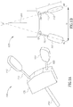
Fig. 1A shows a schematic illustration of a Twist Controller in accordance with an embodiment of the disclosure; -
Fig. 1B shows a top view of the Twist Controller shown inFig. 1A ; -
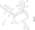
Fig. 1C shows an alternative Twist Controller comprising alternative knobs; -
Fig. 2A shows a schematic illustration of a Twist Controller in accordance with an embodiment of the disclosure; -
Fig. 2B shows a top view of the Twist Controller shown inFig. 2A ; -
Fig. 3 shows a schematic illustration of an alternative Twist Controller in accordance with an embodiment of the disclosure; -
Figs. 4A-4E shows a schematic illustration of a first rotatable knob and second rotatable knob of a Twist Controller in accordance with an embodiment of the disclosure being rotated, as viewed along each rotatable knob's respective axis of rotation; and -
Fig. 5 shows a schematic illustration of a Twist Controller in accordance with an embodiment of the disclosure installed in a vehicle. - Reference is made to
figs. 1A and 1B , which show schematic illustration of a TwistController 100 in accordance with an embodiment of the disclosure. Twist Controller 100 comprises aleft knob 102 and aright knob 112. Optionally, Twist Controller 100 comprisesshaft 103 that connectsleft knob 102 tobody 130 andshaft 113 that connectsright knob 112 tobody 130.Left knob 102 is rotatable around axis AL andright knob 112 is rotatable around axis AR. In an embodiment of the invention, Twist Controller 100 may be configured such that rotation of one or both ofknobs Fig. 5 ), and Twist Controller may be configured so that when a driver of the automobile rotates one or bothknobs automobile 500 is steered to turn right, and when the driver rotates one or both ofknobs - In an embodiment of the disclosure,
knobs knob 102 and arrow CB forknob 112. By way of example, Twist Controller is configured so that rotating one knob 90 degrees in the CW direction causes the other knob to rotate 90 degrees in the CW direction. Alternatively, a 90 degree CCW rotation of one knob causes the other knob to also rotate 90 degrees in the CCW direction. In an embodiment of the disclosure,knobs steering column 200 such that CW rotation ofknobs 102 and/or 112 causes rotation ofsteering column 200 in one rotational direction, and CCW rotation ofknobs 102 and/or 112 causes rotation ofsteering column 200 in the other rotational direction. Embodiments of the rotational coupling betweenknob 102,knob 112 andsteering column 200 is described further hereinbelow. - In an embodiment of the invention, movement of
knobs knobs body 130 and/orsteering column 200. - In an embodiment of the disclosure,
Twist Controller 100 is configured such that axes AL and AR define an angle X, which may be referred to hereinafter as interknob angle X. Optionally, interknob angle X is between 180 degrees and 10 degrees. Optionally, interknob angle X is between 170 degrees and 10 degrees, between 160 degrees and 20 degrees, between 150 degrees and 30 degrees, between 140 degrees and 40 degrees, between 130 degrees and 50 degrees, between 120 degrees and 60 degrees, or between 110 degrees and 70 degrees. Optionally, interknob angle X is about 90 degrees. Optionally, the interknob angle X may be adjustable for an individual driver's optimal comfort. - The use of knobs rather than a wheel for controlling steering allows for a Twist Controller in accordance with an embodiment of the disclosure to be compact relative to a conventional steering wheel. In an embodiment of the disclosure,
Twist Controller 100 and its components are dimensioned such that an interknob distance D between the distal ends of the two knobs is about the width of a driver's shoulders or less. Optionally, interknob distance D is less than 60 centimeters (cm), less than 45 cm, less than 30 cm, less than 25 cm, less than 20 cm, less than 15 cm, or less than 10 cm. Optionally, the distal end ofknob 102 is a point 20 (shown inFig. 2B ) where axis AL crosses an outer surface ofknob 102 and the distal end ofknob 112 is a point 22 (shown inFig. 2B ) where axis AR crosses an outer surface ofknob 112. - In an embodiment of the disclosure, length L of the knob, measured as the distance between the distal end of a
knob body 130 of the Twist Controller is adjustable. Optionally the length ofshaft shaft 103 andknob 102 may be configured so thatshaft 103 is slidable intoknob 102 to shorten knob length L. It will be appreciated that, in an embodiment of the disclosure, for a given interknob angle X, shortening knob length L for the two knobs results in a shortened interknob distance D. As such, shortening knob length L for the knobs results in a shortened interknob distance D as well. It will also be appreciated that, in an embodiment of the disclosure, a distance betweenshafts body 130 is less than interknob distance D between the handle tips, and the relationship between the two distances is a function of interknob angle X and knob length L. Optionally, length L may be about 30 cm or less, less than 20 cm, less than 10 cm, less than 5 cm or less than 2 cm. Optionally, a width ofknobs - In an embodiment of the disclosure, each of
knobs Figs. 1A-1B , or alternatively a substantially rounded shape. Optionally,Knobs - Reference is now made to
Fig. 1C . In an embodiment of the disclosure, adistal portion 109 of alternative knob 102' has a rounded shape relative to aproximal portion 107 of knob 102' and the proximal portion has a flattened shape relative the distal portion. As shown inFig. 1C , rounded shape ofdistal portion 109 is advantageously shaped to be comfortably gripped within a user's hand palm, while the flattened shape ofproximal portion 107 is advantageously shaped for applying torque on knob 102' with the user's fingers.Fig. 1C also shows adistal portion 119 of alternative knob 112' that is rounded relative to aproximal portion 117 of knob 112', with proximal portion being more flat relative to the distal portion. - In an embodiment of the disclosure, each
rotatable knob rotatable knob - In an embodiment of the disclosure, each
knob - In an embodiment of the disclosure,
knob 102 andknob 112 have the same shape as each other or are enantiomorphs to each other. -
Figs. 2A-2B ,3 and4A-4E schematically illustrate various embodiments of rotational coupling betweenknob 102,knob 112 andsteering column 200. - Reference is made to
Figs. 2A and 2B , which showsTwist Controller 100 withoutouter body 130, and schematically illustrates an optional internal mechanism withinbody 130 for providing rotational coupling betweenknob 102,knob 112 andsteering column 200. In an embodiment of the disclosure,left knob 102 is connected todistal end 104 ofshaft 103, and aproximal end 105 ofshaft 103 is connected to abevel gear 106, such that rotation ofleft knob 102 results in rotation ofbevel gear 106. Moreover,right knob 112 is connected to adistal end 114 ofshaft 113, and aproximal end 115 ofshaft 113 is connected to abevel gear 116, such that rotation ofright knob 102 results in rotation ofbevel gear 116. Bevel gears 106 and 116 are operatively coupled to acentral bevel gear 125 that is connected to asteering column 200, such that rotation of one or both ofknobs steering column 200. Becauseknob 102 andknob 112 are each rotationally coupled through respective bevel gears tosteering column 200 rotation of one ofknobs steering column 200 in an opposite rotational direction. The relationship between the rotational directions is schematically represented by arrow CA forknob 102, arrow CB forknob 112 and arrow CC forsteering column 200. In an embodiment of the disclosure,steering column 200 may comprise or be operatively connected to additional gear mechanisms (not shown inFigs. 2A-2B ) to reverse the rotational direction of the steering column so that is remains the same direction asknobs Figs. 2A-2B ), the radius ofbevel gears bevel gear 125 to have the reducing gear ratio. - Reference is made to
Fig. 3 , which schematically illustrates analternative Twist Controller 300 shown withoutouter body 130. Twist Controller is substantially the same asTwist Controller 100 as shown inFigs. 1A-1B and2A-2B , with the exception that it comprises an additional gear between the bevel gear connected to the shaft and the bevel gear connected to the steering column. As shown inFig. 3 ,bevel gear 106 is operatively coupled tointermediate gear 108, which is operatively coupled to bevel gear 125', andbevel gear 116 is operatively coupled tointermediate gear 118, which is operatively coupled to bevel gear 125'. As such, rotation of one ofknobs steering column 200 in a same rotational direction. The relationship between the rotational directions is schematically represented by arrow CA forknob 102, arrow CB forknob 112 and arrow CC' forsteering column 200. - In an embodiment of the disclosure,
Twist Controller 100 is operable to provide torque feedback toknob 102 andknob 112. With reference toFigs. 2A- 2B and3 , it will be appreciated that just as rotation ofknob 102 orknob 112 causes rotation ofsteering column 200 due to mechanical coupling via bevel gears, rotation ofsteering column 200 will cause rotation ofknobs knob 102 andknob 112 mechanically coupled tosteering column 200 is operable to provide torque feedback responsive to a change in the steering of the vehicle. Alternatively or additionally, even in an embodiment where the coupling ofknobs Twist Controller 100 may comprise an electrical torque actuator (not shown) responsive to the steering of the vehicle operable to apply torque toknob 102 and/orknob 112. - Reference is made to
Figs. 4A-4D , which showknob 102 viewed along rotational axis AL from the knob's distal end towards bevel gear 106 (not shown) andknob 112 viewed along rotational axis AR from the knob's distal end towards bevel gear 116 (not shown). - Assume that knobs 102, 112 are identically shaped, and each knob is indicated with corresponding reference points PL, PR at equivalent locations on the knob. The rotational position of a given reference point may be characterized as being between 0 degrees and 360 degrees, with 0 degrees being defined as the point where the given reference point is vertically highest from the ground, 180 degrees being defined as the point where the given reference is lowest, and 360 degrees being a full revolution.
- In an embodiment of the disclosure, an orientation of
knobs -
Figs. 4A-4E shows and exemplary sequence of coordinated rotation ofknob 102 andknob 112, with the 90 degree offset betweenknob 102 andknob 112 being maintained at various rotational positions.Fig. 4A shows reference point PL onknob 102 is at a 315 degree (or a -45 degree) position and reference point PR onknob 112 at a 45 degree position. As shown inFigs. 4A-4B , if theknob 102 gets rotated CW so that reference point PL is rotated from a 315 degree position to a 0 degrees position, thenknob 112 simultaneously rotates such that the reference point PR moves CW from a 45 degree position to a 90 degrees position. As shown inFigs. 4B-4C , whenknob 102 gets rotated so that reference point PL is rotated CW from a 0 degree position to a 45 degrees position, thenknob 112 simultaneously rotates such that the reference point PR moves from a 90 degree position to a 135 degrees position. As shown inFigs. 4C-4D , whenknob 102 gets rotated so that reference point PL is rotated CW from a 45 degree position to a 90 degrees position, thenknob 112 simultaneously rotates such that the reference point PR moves from a 135 degree position to a 180 degrees position. As shown inFigs. 4D-4E , whenknob 102 gets rotated so that reference point PL is rotated CW from a 90 degree position to a 135 degrees position, thenknob 112 simultaneously rotates such that the reference point PR moves from a 180 degree position to a 245 degrees position. - A human hand held out, with the radial styloid as a reference point for determining angular position and 0 degrees being the highest vertical point, is configured to easily rotate between about -45 degree and about 45 degree positions. As shown in
Figs. 4A-4E ,knob 102 andknob 112 are shaped having order 2 rotational symmetry such that the knob has a same appearance after being rotated 180 degrees around the rotation axis, and is flattened in shape. Due to the shape ofknob 102,knob 102 is positioned to be advantageously rotated by a driver when reference point PL ofknob 102 is positioned between the -45 degree and 45 degree positions or between about the 135 degree and 225 degree positions. The above is also the case forknob 112. - In an embodiment of the disclosure, when
knob 102 is rotated by the user's left hand from the knob's -45 degree position to 45 degree position (Fig. 4A to Fig. 4C ),knob 112 becomes positioned to be in the 135 degree position, and thus positioned to be advantageously rotated by the user's right hand. Afterknob 112 is rotated from the knob's 135 degree position to 225 degree position (Fig. 4C to Fig. 4E ),knob 102 becomes positioned to be in the 135 degree position, and thus positioned to be advantageously rotated by the user's left hand. As a result, each time a driver completes a rotation of one knob within the anatomical range of easy wrist rotation, the other knob is advantageously positioned for easy rotation by the other hand. - Reference is now made to
Fig. 5 , which schematically showsautomobile 500 comprisingTwist Controller 100. In an embodiment of the disclosure,Twist Controller 100 is dimensioned to be less obstructive to a driver compared to a typical steering wheel. By way of example,Twist Controller 100, compared to a typical steering wheel, is less obstructive of the driver's view ofdashboard 510 and it's components, by way of example dials 512, 514 andflatscreen display 516, and is less likely to strike a driver's knees when the driver is entering or exitingautomobile 500. In an embodiment of the disclosure, orientation ofTwist Controller 100 with respect todashboard 510 may be adjustable in order to improve drive comfort while using the Twist Controller to steerautomobile 500, or to improve clearance to allow the driver to more easily exit and enter the vehicle. In an embodiment of the disclosure,Twist Controller 100 may be configured to be made further unobtrusive when not in use, by way of example whenvehicle 500 is not being driven or whenvehicle 500 is being controlled by a computer-based autonomous driving system. Optionally, the knobs may be configured to be shortened or collapsed to be flat againstdashboard 510 when not in use. Optionally,Twist controller 100 may be kept inside an indentation or a compartment withindashboard 510 when not in use, and slid or ejected out, beyond the surface ofdashboard 510, when use of the Twist Controller is needed or desired by the driver. The location for mountingTwist Controller 100 in the present disclosure is not limited to the mounting location as shown infigure 5 , especially in an embodiment where the Twist Controller comprises an electronic rotation controller configured to register rotation of one or both knobs to control powered rotation of the steering column responsive to knob rotation, and thus it is not required to be mechanically coupled to a steering column. By way of example,Twist Controller 100 may be mounted on the driver's seat or the ceiling. Alternatively,Twist Controller 100 may be a stand-alone device that is operatively connectable tovehicle 500 through a wire or wireless connection. - Descriptions of embodiments of the disclosure in the present application are provided by way of example and are not intended to limit the scope of the disclosure. The described embodiments comprise different features, not all of which are required in all embodiments of the disclosure. Some embodiments utilize only some of the features or possible combinations of the features. Variations of embodiments of the disclosure that are described, and embodiments of the disclosure comprising different combinations of features noted in the described embodiments, will occur to persons of the art. The scope of the disclosure is limited only by the claims.
Claims (15)
- A vehicle steering input device (100) comprising:a first knob (102) configured to be rotatable around a first axis of rotation (AL) and operatively coupled to a steering column (200) so that rotating the first knob results in rotation of the steering column; anda second knob (112) configured to be rotatable around a second axis of rotation (AR) and operatively coupled to rotate the steering column so that rotating the second knob results in rotating the steering column,wherein the first and second rotatable knobs are operatively coupled so that rotating one knob in a clockwise or counter clockwise direction results in rotating the other knob in a same direction;
characterized in that the first axis of rotation and the second axis of rotation define an angle (X). - The vehicle steering input device according to claim 1, wherein the angle (X) formed between the first and second axes of rotation (AL, AR) is between 180 degrees and 10 degrees.
- The vehicle steering input device according to claim 1 or claim 2, wherein the angle (X) is between 170 degrees and 10 degrees, between 160 degrees and 20 degrees, between 150 degrees and 30 degrees, between 140 degrees and 40 degrees, between 130 degrees and 50 degrees, between 120 degrees and 60 degrees, between 110 degrees and 70 degrees, or about 90 degrees.
- The vehicle steering input device according to any one of the preceding claims, wherein the orientation of the first and second knobs (102, 112) around their respective axes of rotation (AL, AR) are offset by 90 degrees with respect to each other, and the offset remains 90 degrees regardless of the angular position of the first and second rotatable knobs about their respective axes of rotation.
- The vehicle steering input device according to any one of the preceding claims, wherein rotation of the first and second knobs (102, 112) are mechanically coupled to rotation of the steering column (200).
- The vehicle steering input device according to any one of the preceding claims, further comprising an electronic rotation controller configured to register rotation of one or both knobs (102, 112) and control powered rotation of the steering column (200) responsive to knob rotation.
- The vehicle steering input device according to any one of the preceding claims, further comprising an electrical feedback actuator that applies torque to the first and/or second knobs (102, 112) responsive to force applied to the steering column (200).
- The vehicle steering input device according to any one of the preceding claims, wherein for at least one of the first and second knobs (102, 112), a distal portion (109, 119) of the knob is characterized by a rounded shape relative to a proximal portion (107, 117) of the knob.
- A vehicle steering input device (100) comprising:a first knob (102) configured to be rotatable around a first axis of rotation (AL) and operatively coupled to a steering column (200) so that rotating the first knob results in rotation of the steering column; anda second knob (112) configured to be rotatable around a second axis of rotation (AR) and operatively coupled to rotate the steering column so that rotating the second knob results in rotating the steering column,wherein the first and second knobs are operatively coupled so that rotating one knob in a clockwise or counter clockwise direction results in rotating the other knob in a same direction;
characterized in that the orientation of the first and second knobs around their respective axes of rotation are offset by 90 degrees with respect to each other, and the offset remains 90 degrees regardless of the angular position of the first and second rotatable knobs about their respective axes of rotation. - The vehicle steering input device according to claim 9, wherein the first axis of rotation (AL) and the second axis of rotation (AR) define an angle (X).
- The vehicle steering input device according to claim 9 or claim 10, wherein an angle (X) formed between the first and second axes of rotation (AL, AR) is between 180 degrees and 10 degrees.
- The vehicle steering input device according to any one of claims 9-11, wherein rotation of the first and second knobs (102, 112) are mechanically coupled to rotation of the steering column (200).
- The vehicle steering input device according to any one of claims 9-12, further comprising an electronic rotation controller configured to register rotation of one or both knobs (102, 112) and control powered rotation of the steering column (200) responsive to knob rotation.
- The vehicle steering input device according to any one of claims 9-13, further comprising an electrical feedback actuator that applies torque to the first and/or second knobs (102, 112) responsive to force applied to the steering column (200).
- The vehicle steering input device according to any one of claims 9-14, wherein for at least one of the first and second knobs (102, 112), a distal portion (109, 119) of the knob is characterized by a rounded shape relative to a proximal portion (107, 117) of the knob and the proximal portion of the knob has a flattened shape relative the distal portion.
Applications Claiming Priority (1)
| Application Number | Priority Date | Filing Date | Title |
|---|---|---|---|
| PCT/IB2016/054014 WO2018007848A1 (en) | 2016-07-05 | 2016-07-05 | Compact steering |
Publications (2)
| Publication Number | Publication Date |
|---|---|
| EP3292035A1 EP3292035A1 (en) | 2018-03-14 |
| EP3292035B1 true EP3292035B1 (en) | 2018-09-05 |
Family
ID=56609880
Family Applications (1)
| Application Number | Title | Priority Date | Filing Date |
|---|---|---|---|
| EP16747910.4A Active EP3292035B1 (en) | 2016-07-05 | 2016-07-05 | Compact steering |
Country Status (5)
| Country | Link |
|---|---|
| US (1) | US10457316B2 (en) |
| EP (1) | EP3292035B1 (en) |
| JP (1) | JP2019520264A (en) |
| CN (1) | CN109415076B (en) |
| WO (1) | WO2018007848A1 (en) |
Families Citing this family (2)
| Publication number | Priority date | Publication date | Assignee | Title |
|---|---|---|---|---|
| US10919558B2 (en) * | 2017-12-19 | 2021-02-16 | Mando Corporation | Steering apparatus for vehicle |
| DE102020118867B3 (en) * | 2020-07-16 | 2022-01-05 | Bayerische Motoren Werke Aktiengesellschaft | Steering device for a vehicle and a vehicle equipped therewith |
Family Cites Families (11)
| Publication number | Priority date | Publication date | Assignee | Title |
|---|---|---|---|---|
| US3176537A (en) | 1961-09-14 | 1965-04-06 | Gen Motors Corp | Steering mechanism |
| US3282124A (en) * | 1963-11-22 | 1966-11-01 | Gen Motors Corp | Steering control arrangement |
| US3312123A (en) | 1965-03-11 | 1967-04-04 | Ford Motor Co | Vehicle steering control |
| FR1493060A (en) * | 1966-07-13 | 1967-08-25 | Steering device for motor vehicle, ensuring the safety of the driver in the event of an accident | |
| FR1493360A (en) | 1966-09-21 | 1967-08-25 | Petkus Landmaschinenwerk Veb | scrubber, especially for harvest obtained with the combine harvester |
| US5755142A (en) * | 1996-07-30 | 1998-05-26 | Jacoby; Byron H. | Steering mechanism |
| US7726692B2 (en) * | 2003-12-01 | 2010-06-01 | Honda Motor Co., Ltd. | Steering handle and steering system |
| DE102004046321A1 (en) * | 2004-09-17 | 2006-04-06 | Takata-Petri Ag | steering wheel |
| CN101287636B (en) * | 2005-10-12 | 2011-02-02 | 纳尔迪-个人股份公司 | Steering apparatus |
| US8960043B2 (en) * | 2010-03-29 | 2015-02-24 | Toyota Jidosha Kabushiki Kaisha | Steering device |
| CN203318484U (en) * | 2013-05-06 | 2013-12-04 | 东风商用车有限公司 | Double-steering-wheel steering transmission device of coach passenger car |
-
2016
- 2016-07-05 US US15/549,160 patent/US10457316B2/en active Active
- 2016-07-05 CN CN201680087439.XA patent/CN109415076B/en active Active
- 2016-07-05 EP EP16747910.4A patent/EP3292035B1/en active Active
- 2016-07-05 WO PCT/IB2016/054014 patent/WO2018007848A1/en active Application Filing
- 2016-07-05 JP JP2018569127A patent/JP2019520264A/en active Pending
Also Published As
| Publication number | Publication date |
|---|---|
| CN109415076A (en) | 2019-03-01 |
| US10457316B2 (en) | 2019-10-29 |
| CN109415076B (en) | 2020-05-05 |
| JP2019520264A (en) | 2019-07-18 |
| WO2018007848A1 (en) | 2018-01-11 |
| EP3292035A1 (en) | 2018-03-14 |
| US20190111963A1 (en) | 2019-04-18 |
Similar Documents
| Publication | Publication Date | Title |
|---|---|---|
| JP5131523B2 (en) | Vehicle steering system | |
| EP2086782B1 (en) | Vehicle control systems and methods | |
| EP3292035B1 (en) | Compact steering | |
| EP3293600A2 (en) | Three-axis motion joystick | |
| WO2005054032A1 (en) | Steering handle and steering device | |
| US6695092B2 (en) | Steering actuator system | |
| EP0376457A2 (en) | Steering gear for the roadwheels of a vehicle | |
| US8376379B2 (en) | Steering apparatus for vehicle | |
| CN112722059A (en) | Torque feedback assembly for a vehicle steering column | |
| JP4252888B2 (en) | Steering handle for vehicles | |
| KR100580534B1 (en) | Motor driven steering column system using gear change tilt- telescopic mode in vehicle | |
| JPH09164968A (en) | Omnidirectional moving vehicle and its control method | |
| WO1993009971A1 (en) | Steering linkage | |
| JP4191643B2 (en) | Vehicle steering system | |
| JP4432596B2 (en) | Rack and pinion steering system | |
| JP2005246987A (en) | Steering operation device for vehicle | |
| US11945531B2 (en) | Steering device | |
| JP2002120588A (en) | Shift switch device for automobile | |
| JP2003327148A (en) | Steering gear for vehicle | |
| KR200340027Y1 (en) | steering column for vehicle having auto-tilting and telescopic device | |
| CN108137082A (en) | For the steering gear of vehicle | |
| JPH0741665Y2 (en) | Self-propelled steering wheel device | |
| JPH0733706U (en) | Portable tire replacement aid | |
| JP2004230937A (en) | Adjusting device of rotation neutral position of steering wheel in automobile | |
| JPH0236786Y2 (en) |
Legal Events
| Date | Code | Title | Description |
|---|---|---|---|
| STAA | Information on the status of an ep patent application or granted ep patent |
Free format text: STATUS: UNKNOWN |
|
| STAA | Information on the status of an ep patent application or granted ep patent |
Free format text: STATUS: THE INTERNATIONAL PUBLICATION HAS BEEN MADE |
|
| PUAI | Public reference made under article 153(3) epc to a published international application that has entered the european phase |
Free format text: ORIGINAL CODE: 0009012 |
|
| STAA | Information on the status of an ep patent application or granted ep patent |
Free format text: STATUS: REQUEST FOR EXAMINATION WAS MADE |
|
| GRAP | Despatch of communication of intention to grant a patent |
Free format text: ORIGINAL CODE: EPIDOSNIGR1 |
|
| STAA | Information on the status of an ep patent application or granted ep patent |
Free format text: STATUS: GRANT OF PATENT IS INTENDED |
|
| 17P | Request for examination filed |
Effective date: 20170908 |
|
| AK | Designated contracting states |
Kind code of ref document: A1 Designated state(s): AL AT BE BG CH CY CZ DE DK EE ES FI FR GB GR HR HU IE IS IT LI LT LU LV MC MK MT NL NO PL PT RO RS SE SI SK SM TR |
|
| AX | Request for extension of the european patent |
Extension state: BA ME |
|
| INTG | Intention to grant announced |
Effective date: 20180223 |
|
| GRAS | Grant fee paid |
Free format text: ORIGINAL CODE: EPIDOSNIGR3 |
|
| GRAA | (expected) grant |
Free format text: ORIGINAL CODE: 0009210 |
|
| STAA | Information on the status of an ep patent application or granted ep patent |
Free format text: STATUS: THE PATENT HAS BEEN GRANTED |
|
| DAV | Request for validation of the european patent (deleted) | ||
| DAX | Request for extension of the european patent (deleted) | ||
| AK | Designated contracting states |
Kind code of ref document: B1 Designated state(s): AL AT BE BG CH CY CZ DE DK EE ES FI FR GB GR HR HU IE IS IT LI LT LU LV MC MK MT NL NO PL PT RO RS SE SI SK SM TR |
|
| REG | Reference to a national code |
Ref country code: GB Ref legal event code: FG4D |
|
| REG | Reference to a national code |
Ref country code: CH Ref legal event code: EP |
|
| REG | Reference to a national code |
Ref country code: AT Ref legal event code: REF Ref document number: 1037453 Country of ref document: AT Kind code of ref document: T Effective date: 20180915 |
|
| REG | Reference to a national code |
Ref country code: IE Ref legal event code: FG4D |
|
| REG | Reference to a national code |
Ref country code: DE Ref legal event code: R096 Ref document number: 602016005381 Country of ref document: DE |
|
| REG | Reference to a national code |
Ref country code: NL Ref legal event code: MP Effective date: 20180905 |
|
| REG | Reference to a national code |
Ref country code: LT Ref legal event code: MG4D |
|
| PG25 | Lapsed in a contracting state [announced via postgrant information from national office to epo] |
Ref country code: FI Free format text: LAPSE BECAUSE OF FAILURE TO SUBMIT A TRANSLATION OF THE DESCRIPTION OR TO PAY THE FEE WITHIN THE PRESCRIBED TIME-LIMIT Effective date: 20180905 Ref country code: LT Free format text: LAPSE BECAUSE OF FAILURE TO SUBMIT A TRANSLATION OF THE DESCRIPTION OR TO PAY THE FEE WITHIN THE PRESCRIBED TIME-LIMIT Effective date: 20180905 Ref country code: RS Free format text: LAPSE BECAUSE OF FAILURE TO SUBMIT A TRANSLATION OF THE DESCRIPTION OR TO PAY THE FEE WITHIN THE PRESCRIBED TIME-LIMIT Effective date: 20180905 Ref country code: NO Free format text: LAPSE BECAUSE OF FAILURE TO SUBMIT A TRANSLATION OF THE DESCRIPTION OR TO PAY THE FEE WITHIN THE PRESCRIBED TIME-LIMIT Effective date: 20181205 Ref country code: GR Free format text: LAPSE BECAUSE OF FAILURE TO SUBMIT A TRANSLATION OF THE DESCRIPTION OR TO PAY THE FEE WITHIN THE PRESCRIBED TIME-LIMIT Effective date: 20181206 Ref country code: SE Free format text: LAPSE BECAUSE OF FAILURE TO SUBMIT A TRANSLATION OF THE DESCRIPTION OR TO PAY THE FEE WITHIN THE PRESCRIBED TIME-LIMIT Effective date: 20180905 Ref country code: BG Free format text: LAPSE BECAUSE OF FAILURE TO SUBMIT A TRANSLATION OF THE DESCRIPTION OR TO PAY THE FEE WITHIN THE PRESCRIBED TIME-LIMIT Effective date: 20181205 |
|
| REG | Reference to a national code |
Ref country code: AT Ref legal event code: MK05 Ref document number: 1037453 Country of ref document: AT Kind code of ref document: T Effective date: 20180905 |
|
| PG25 | Lapsed in a contracting state [announced via postgrant information from national office to epo] |
Ref country code: HR Free format text: LAPSE BECAUSE OF FAILURE TO SUBMIT A TRANSLATION OF THE DESCRIPTION OR TO PAY THE FEE WITHIN THE PRESCRIBED TIME-LIMIT Effective date: 20180905 Ref country code: LV Free format text: LAPSE BECAUSE OF FAILURE TO SUBMIT A TRANSLATION OF THE DESCRIPTION OR TO PAY THE FEE WITHIN THE PRESCRIBED TIME-LIMIT Effective date: 20180905 Ref country code: AL Free format text: LAPSE BECAUSE OF FAILURE TO SUBMIT A TRANSLATION OF THE DESCRIPTION OR TO PAY THE FEE WITHIN THE PRESCRIBED TIME-LIMIT Effective date: 20180905 |
|
| PG25 | Lapsed in a contracting state [announced via postgrant information from national office to epo] |
Ref country code: CZ Free format text: LAPSE BECAUSE OF FAILURE TO SUBMIT A TRANSLATION OF THE DESCRIPTION OR TO PAY THE FEE WITHIN THE PRESCRIBED TIME-LIMIT Effective date: 20180905 Ref country code: IS Free format text: LAPSE BECAUSE OF FAILURE TO SUBMIT A TRANSLATION OF THE DESCRIPTION OR TO PAY THE FEE WITHIN THE PRESCRIBED TIME-LIMIT Effective date: 20190105 Ref country code: EE Free format text: LAPSE BECAUSE OF FAILURE TO SUBMIT A TRANSLATION OF THE DESCRIPTION OR TO PAY THE FEE WITHIN THE PRESCRIBED TIME-LIMIT Effective date: 20180905 Ref country code: PL Free format text: LAPSE BECAUSE OF FAILURE TO SUBMIT A TRANSLATION OF THE DESCRIPTION OR TO PAY THE FEE WITHIN THE PRESCRIBED TIME-LIMIT Effective date: 20180905 Ref country code: NL Free format text: LAPSE BECAUSE OF FAILURE TO SUBMIT A TRANSLATION OF THE DESCRIPTION OR TO PAY THE FEE WITHIN THE PRESCRIBED TIME-LIMIT Effective date: 20180905 Ref country code: IT Free format text: LAPSE BECAUSE OF FAILURE TO SUBMIT A TRANSLATION OF THE DESCRIPTION OR TO PAY THE FEE WITHIN THE PRESCRIBED TIME-LIMIT Effective date: 20180905 Ref country code: RO Free format text: LAPSE BECAUSE OF FAILURE TO SUBMIT A TRANSLATION OF THE DESCRIPTION OR TO PAY THE FEE WITHIN THE PRESCRIBED TIME-LIMIT Effective date: 20180905 Ref country code: AT Free format text: LAPSE BECAUSE OF FAILURE TO SUBMIT A TRANSLATION OF THE DESCRIPTION OR TO PAY THE FEE WITHIN THE PRESCRIBED TIME-LIMIT Effective date: 20180905 |
|
| PG25 | Lapsed in a contracting state [announced via postgrant information from national office to epo] |
Ref country code: SM Free format text: LAPSE BECAUSE OF FAILURE TO SUBMIT A TRANSLATION OF THE DESCRIPTION OR TO PAY THE FEE WITHIN THE PRESCRIBED TIME-LIMIT Effective date: 20180905 Ref country code: SK Free format text: LAPSE BECAUSE OF FAILURE TO SUBMIT A TRANSLATION OF THE DESCRIPTION OR TO PAY THE FEE WITHIN THE PRESCRIBED TIME-LIMIT Effective date: 20180905 Ref country code: PT Free format text: LAPSE BECAUSE OF FAILURE TO SUBMIT A TRANSLATION OF THE DESCRIPTION OR TO PAY THE FEE WITHIN THE PRESCRIBED TIME-LIMIT Effective date: 20190105 |
|
| REG | Reference to a national code |
Ref country code: DE Ref legal event code: R097 Ref document number: 602016005381 Country of ref document: DE |
|
| PLBE | No opposition filed within time limit |
Free format text: ORIGINAL CODE: 0009261 |
|
| STAA | Information on the status of an ep patent application or granted ep patent |
Free format text: STATUS: NO OPPOSITION FILED WITHIN TIME LIMIT |
|
| PG25 | Lapsed in a contracting state [announced via postgrant information from national office to epo] |
Ref country code: ES Free format text: LAPSE BECAUSE OF FAILURE TO SUBMIT A TRANSLATION OF THE DESCRIPTION OR TO PAY THE FEE WITHIN THE PRESCRIBED TIME-LIMIT Effective date: 20180905 Ref country code: DK Free format text: LAPSE BECAUSE OF FAILURE TO SUBMIT A TRANSLATION OF THE DESCRIPTION OR TO PAY THE FEE WITHIN THE PRESCRIBED TIME-LIMIT Effective date: 20180905 |
|
| 26N | No opposition filed |
Effective date: 20190606 |
|
| PG25 | Lapsed in a contracting state [announced via postgrant information from national office to epo] |
Ref country code: SI Free format text: LAPSE BECAUSE OF FAILURE TO SUBMIT A TRANSLATION OF THE DESCRIPTION OR TO PAY THE FEE WITHIN THE PRESCRIBED TIME-LIMIT Effective date: 20180905 |
|
| PG25 | Lapsed in a contracting state [announced via postgrant information from national office to epo] |
Ref country code: MC Free format text: LAPSE BECAUSE OF FAILURE TO SUBMIT A TRANSLATION OF THE DESCRIPTION OR TO PAY THE FEE WITHIN THE PRESCRIBED TIME-LIMIT Effective date: 20180905 |
|
| REG | Reference to a national code |
Ref country code: CH Ref legal event code: PL |
|
| PG25 | Lapsed in a contracting state [announced via postgrant information from national office to epo] |
Ref country code: TR Free format text: LAPSE BECAUSE OF FAILURE TO SUBMIT A TRANSLATION OF THE DESCRIPTION OR TO PAY THE FEE WITHIN THE PRESCRIBED TIME-LIMIT Effective date: 20180905 |
|
| REG | Reference to a national code |
Ref country code: BE Ref legal event code: MM Effective date: 20190731 |
|
| PG25 | Lapsed in a contracting state [announced via postgrant information from national office to epo] |
Ref country code: LI Free format text: LAPSE BECAUSE OF NON-PAYMENT OF DUE FEES Effective date: 20190731 Ref country code: CH Free format text: LAPSE BECAUSE OF NON-PAYMENT OF DUE FEES Effective date: 20190731 Ref country code: LU Free format text: LAPSE BECAUSE OF NON-PAYMENT OF DUE FEES Effective date: 20190705 Ref country code: BE Free format text: LAPSE BECAUSE OF NON-PAYMENT OF DUE FEES Effective date: 20190731 |
|
| PG25 | Lapsed in a contracting state [announced via postgrant information from national office to epo] |
Ref country code: IE Free format text: LAPSE BECAUSE OF NON-PAYMENT OF DUE FEES Effective date: 20190705 |
|
| PG25 | Lapsed in a contracting state [announced via postgrant information from national office to epo] |
Ref country code: CY Free format text: LAPSE BECAUSE OF FAILURE TO SUBMIT A TRANSLATION OF THE DESCRIPTION OR TO PAY THE FEE WITHIN THE PRESCRIBED TIME-LIMIT Effective date: 20180905 |
|
| PG25 | Lapsed in a contracting state [announced via postgrant information from national office to epo] |
Ref country code: MT Free format text: LAPSE BECAUSE OF FAILURE TO SUBMIT A TRANSLATION OF THE DESCRIPTION OR TO PAY THE FEE WITHIN THE PRESCRIBED TIME-LIMIT Effective date: 20180905 Ref country code: HU Free format text: LAPSE BECAUSE OF FAILURE TO SUBMIT A TRANSLATION OF THE DESCRIPTION OR TO PAY THE FEE WITHIN THE PRESCRIBED TIME-LIMIT; INVALID AB INITIO Effective date: 20160705 |
|
| PG25 | Lapsed in a contracting state [announced via postgrant information from national office to epo] |
Ref country code: MK Free format text: LAPSE BECAUSE OF FAILURE TO SUBMIT A TRANSLATION OF THE DESCRIPTION OR TO PAY THE FEE WITHIN THE PRESCRIBED TIME-LIMIT Effective date: 20180905 |
|
| PGFP | Annual fee paid to national office [announced via postgrant information from national office to epo] |
Ref country code: FR Payment date: 20230620 Year of fee payment: 8 |
|
| PGFP | Annual fee paid to national office [announced via postgrant information from national office to epo] |
Ref country code: GB Payment date: 20230618 Year of fee payment: 8 |
|
| PGFP | Annual fee paid to national office [announced via postgrant information from national office to epo] |
Ref country code: DE Payment date: 20230628 Year of fee payment: 8 |