EP3291929B1 - Method and apparatus for curling an article - Google Patents
Method and apparatus for curling an article Download PDFInfo
- Publication number
- EP3291929B1 EP3291929B1 EP16722998.8A EP16722998A EP3291929B1 EP 3291929 B1 EP3291929 B1 EP 3291929B1 EP 16722998 A EP16722998 A EP 16722998A EP 3291929 B1 EP3291929 B1 EP 3291929B1
- Authority
- EP
- European Patent Office
- Prior art keywords
- curl
- rollers
- radius
- article
- groove
- Prior art date
- Legal status (The legal status is an assumption and is not a legal conclusion. Google has not performed a legal analysis and makes no representation as to the accuracy of the status listed.)
- Active
Links
Images


Classifications
-
- B—PERFORMING OPERATIONS; TRANSPORTING
- B21—MECHANICAL METAL-WORKING WITHOUT ESSENTIALLY REMOVING MATERIAL; PUNCHING METAL
- B21D—WORKING OR PROCESSING OF SHEET METAL OR METAL TUBES, RODS OR PROFILES WITHOUT ESSENTIALLY REMOVING MATERIAL; PUNCHING METAL
- B21D51/00—Making hollow objects
- B21D51/16—Making hollow objects characterised by the use of the objects
- B21D51/26—Making hollow objects characterised by the use of the objects cans or tins; Closing same in a permanent manner
- B21D51/2615—Edge treatment of cans or tins
- B21D51/2623—Curling
-
- B—PERFORMING OPERATIONS; TRANSPORTING
- B31—MAKING ARTICLES OF PAPER, CARDBOARD OR MATERIAL WORKED IN A MANNER ANALOGOUS TO PAPER; WORKING PAPER, CARDBOARD OR MATERIAL WORKED IN A MANNER ANALOGOUS TO PAPER
- B31F—MECHANICAL WORKING OR DEFORMATION OF PAPER, CARDBOARD OR MATERIAL WORKED IN A MANNER ANALOGOUS TO PAPER
- B31F1/00—Mechanical deformation without removing material, e.g. in combination with laminating
- B31F1/008—Shaping of tube ends, e.g. flanging, belling, closing, rim-rolling or corrugating; Fixing elements to tube ends
- B31F1/0087—Rim-rolling
Definitions
- the present invention relates generally to the field of forming or processing an article, such as a beverage container or can. More specifically, the invention relates to an apparatus and method for forming a curl on an article.
- Containers used, for example, for packaging liquid products often include a container body that terminates at the top end with a radially outwardly, downwardly, and inwardly directed curl.
- a container body that terminates at the top end with a radially outwardly, downwardly, and inwardly directed curl.
- the purpose of the curl is to support the valve cup and a gasket to seal against and strengthen the area where a connection is made to the valve cup.
- WO 86/03471 asserts that formation of an outwardly extending curl as the upper rim of a pail or drum having a cylindrical wall by curling the peripheral edge through greater than 360° relative to the cylindrical wall forms a strong curl able to support, with the aid of a gasket, a leak proof seal during dangerous goods testing.
- the lugs When used with a lug-cover lid, the lugs may be clenched beneath the curl through a re-entrant portion enhancing the security of the seal.
- Methods of forming the curl in a two-stage operation by forming primary and then secondary curl components, and an alternative lug configuration are also disclosed.
- US 7464573 B2 forming the basis for the preamble of the independent claims, discloses an apparatus for providing a curl on a top edge of a can that comprises a forming head; and a forming turret with a push ram to load the can into the forming head.
- the forming head includes a plurality of independent rollers mounted on a common head.
- the plurality of rollers includes a first set of rollers configured to form an inner portion of a curl and a second set of rollers configured to form an outer portion of the curl.
- an apparatus for forming a curl on an article comprises a first forming tooling having a first set of rollers mounted on a common head.
- the first set of rollers has a respective groove having a first groove radius.
- the first set of rollers are configured to form a first curl having a first curl radius on an open end of the article.
- the apparatus further comprises a first rotating turret configured to load the article into the first forming tooling.
- the article has a welded seam.
- the apparatus further comprises a second forming tooling having a second set of rollers mounted on a common head.
- the second set of rollers has a respective groove having a second groove radius. The second groove radius is larger than the first groove radius.
- the second set of rollers are configured to form a modified curl having a second curl radius near the top of the modified curl and maintain the first curl radius near the bottom of the modified curl.
- the apparatus further comprises a second rotating turret configured to load the article into the second forming tooling.
- the apparatus further comprises a first transfer star wheel configured to transfer the article from the first rotating turret to the second rotating turret.
- a method of forming a curl in a top edge of an article comprises feeding an article into a first rotating turret and loading the article into a first forming tooling having a first set of rollers.
- the method further comprises using the first set of rollers to form a curl in the top edge of the article.
- the curl has a first radius.
- the method further comprises transferring the article having the curl to a second rotating turret and loading the article having the curl into a second forming tooling having a second set of rollers.
- the method further comprises using the second set of rollers to modify the curl.
- the modified curl has a second radius near the top of the modified curl , the second radius being larger than the first radius, the first radius being generally maintained near the bottom of the modified curl.
- systems and methods are described for improving the integrity of containers that include a curl at the top end of the container.
- FIG. 1 illustrates an exemplary article 105 for forming a curl thereon.
- the article 105 may be a can, any suitable food or beverage container, jar, bottle, or any other suitable article.
- the article 105 has an open end, opposite closed end, and a sidewall extending from the closed end. Alternatively, the article 105 may be open at both ends. A top, lid, or other closure may be added to the article 105 after the curling process.
- Curling describes a process by which the open end of a can 105 is formed into a rounded, flat, or other shape.
- a curling process that may be used with the present invention is described in U.S. Patent No. 7,464,573 .
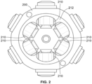
- a forming head or tooling 200 as shown, for example, in FIGs. 1 and 2 , may provide a curl comprising a rounded section and/or a flat section.
- the forming tooling 200 may include a first set of rollers 210 as shown, for example, in FIGs. 1 , 2 , 3a, 3b .
- each of the plurality of rollers 210 is generally the same on the forming tooling 200, it is contemplated that two or more different kinds of rollers may be used on a single forming tooling and/or the position of the rollers on the forming tooling may be non-uniform (e.g., alternating positions, staggered, etc.).
- Curling may turn the open edge of the can 105 greater than 90° from its normal (initial) orientation.
- curling may comprise turning the open edge of the can 105 greater than, equal to, or less than 90°.
- cans 105 may be fed into a first continuously rotating turret (e.g., turret 410a of FIG. 4 ), either from an infeed track or from a preceding process turret, which may be part of a machine line 411.
- FIG. 4 illustrates a turret star wheel 402a passing a can 105 to a first continuously rotating forming turret 410a of a can curling process according to one embodiment. While the first rotating turret 410a is rotating with the can 105 inserted into a first forming station therein, the can 105 is loaded into a first forming tooling (e.g., forming tooling 200 of FIG.
- each of the sets of rollers includes a respective pilot with an extended portion and a groove.
- the groove is generally concave and has a groove radius, as shown, for example, in FIGs. 5a-5d .
- the first set of rollers includes a respective first groove having a first groove radius.
- the first set of rollers is used to form a preliminary first curl having a first curl radius on an end of the can 105.
- the curl radius is generally measured from a straight sidewall 105A of the container 105 (see FIG. 1 ) to a midpoint measured horizontally between the straight sidewall 105A and the outer portion of the curl (see, e.g., FIGs. 5a-5d below).
- the can 105 is withdrawn from the first forming tooling.
- the can 105 is then transferred from the first rotating turret 410a onto a second rotating turret 410b via a transfer star wheel 402b (see FIG. 4 ).
- the second rotating turret 410b is rotating with the can 105 inserted into a second forming station thereon, the can 105 is loaded into a second forming tooling having a second set of rollers mounted on a common head.
- the second set of rollers has a respective second concave groove having a larger groove radius than the first groove radius of the first set of rollers.
- the second set of rollers (and the second grooves thereon) is used to modify the first curl formed by the first set of rollers into a second, modified curl having a second curl radius, which is larger than the first curl radius of the first curl.
- the container 105 is less susceptible to cracking or splitting because less material is displaced and placed under tension.
- the can is then withdrawn from the second forming tooling and may then be transferred from the second rotating turret 410b onto another process turret (not shown) or to a discharge track or star wheel 402c, in the direction illustrated by the arrows in FIG. 4 .
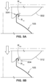
- FIGs. 5a-5d One example of a multiple stage process for forming a curl on an article in accordance with the present disclosure is shown in FIGs. 5a-5d .
- a can 105 positioned in a first rotating turret e.g., turret 410a of FIG. 4
- the first set of rollers 502 has a first groove radius R 1G .
- the first groove radius R 1G may range from about 0.01 to about 0.04 inches.
- the resulting first curl 504 has a first curl radius R 1C that is smaller than a final curl radius R FC (see FIG. 5d ) such that less can material is displaced and less tension is created as the can material moves outward and is tucked inward, thereby lessening the chances for a crack or split in the can material.
- the resulting can 105 is then withdrawn from the first forming tooling and transferred, via the first star wheel 402b, to a second rotating turret 410b, where the can 105 is loaded into a second forming station and then into a second forming tooling having a second set of rollers 512, a portion of which is shown in FIG. 5b .
- the second set of rollers 512 has a second groove radius R 2G that is larger than the first groove radius R 1G , as shown in FIG. 5b.
- FIG. 5b shows the can 105 and first curl 504 prior to modification by the second set of rollers 512.
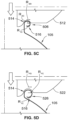
- the first curl 504 is modified into a second modified curl 506, as shown in FIG. 5c .
- the curl radius near the bottom 516 of the modified curl 506 may also be modified (e.g., slightly expand from its originally formed state of FIG. 5a ) during the process shown in FIGs. 5b-5c .
- the first curl radius R 1C near the bottom 516 of the modified curl 506 is smaller than the second curl radius R 2C near the top 514 of the modified curl 506.
- the resulting can is then withdrawn from the second forming station.
- the can 105 may then be transferred to a discharge star wheel.
- the can may be transferred to a third rotating process turret (not shown) into a third forming station via a third star wheel (e.g., star wheel 402c).
- the can may then be loaded into a third forming tooling having a third set of rollers 522.
- the third forming tooling is the final forming tooling.
- any suitable number of process turrets and forming toolings may be used.
- the third set of rollers 522 has a final groove radius R FG that forms a final curl 526 to the desired/specified dimensions.
- the final groove radius R FG is larger than the first groove radius R 1G .
- the groove radius increases as the can moves down the process line. In this way, the tension applied to the can material can be minimized, since less material is displaced during each stage of the process, thereby resulting in less cracking and/or splitting of the can material.
- the groove radius of the third set of rollers (or a set of rollers further down the process line, such as the final set of rollers) may have multiple radii.
- the groove radius may have a combination of larger and smaller radii, one or more straight sections, combinations thereof, or the like such that the final curl conforms to desired/specified dimensions.
- a final curl radius R FC near the top of the resulting, final curl 526 which contacts the third set of rollers 522, expands to generally fit within the final groove radius R FG of the third set of rollers 522.
- the first curl radius R 1C near the bottom 516 of the final curl 526 remains smaller than the final curl radius R FC near the top 514 of the final curl 526.
- the shapes of the curls shown in the illustrated embodiments are generally circular or oval, it is contemplated that other shapes may also be formed, as shown, for example, in FIGs. 6a and 6b .
- the term "radius,” as used herein may still be applied in a corresponding way to non-circular or non-oval geometries and would be measured accordingly, e.g., as the distance between the straight sidewall 105A of the container 105 and the midpoint between the straight sidewall 105A of the container 105A and the outer portion of the curl.
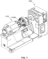
- curling machines are constructed as modules 700, as shown, for example, in FIG. 7 .
- the use of can curling modules allows for the machine line 411 to be assembled/changed to provide as many can curling stages as is required and to allow for the addition of additional stages such as flanging, necking, trimming, expansion, threading, and/or base reforming/reprofiling, which may be added/removed as desired.
- the turret star wheels 402, 410 may be composed of two segments, which are connected to a drive shaft by way of a timing plate. These timing plates are individually adjustable with respect to the respective turret drive shaft in a manner which allows their angular rotational position with respect to the turret drive shaft to be adjusted and then fixed to the degree that the two segments of the turret star wheel which are mounted thereon, are positioned/timed with respect to the transfer star wheels on either side thereof, so that a smooth, continuous, incident-free transfer of cans between the turret star wheels and the respective transfer star wheels, can take place.
- the infeed star wheels, discharge star wheels, and/or the transfer star wheels 402, 410 may be arranged to hold the cans 105 in position using suction.
- the star wheels 402, 410 may have a vacuum port formed in a channel portion(s) that are fluidly communicating with a source of vacuum (negative pneumatic pressure) via a suitable manifold. The vacuum is delivered to the vacuum ports, and the surface area of the cans 105, which are exposed to the suction, is increased to a degree that the cans 105 are stably held in position as each can 105 passes below the transfer star wheel axis of rotation.
- the forming rotating turrets 410 may comprise a positioning star wheel 410S at the straight wall 105A of the can 105, and the forming (curling) tooling 200 (see FIGs. 1 , 2 ) at the open end of the can 105.
- the positioning star wheels 410S help keep the can 105 oriented and aligned with the forming tooling 200 to enable proper curling (forming) of the can 105.
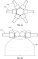
- the forming tooling (head) 200 may comprises multiple independent rollers mounted on a common head 212, as shown, for example, in FIG. 8 .
- the rollers are mounted on bearings 240 (see FIG. 1 ) and are free spinning.
- the rollers 210 are independent such that each roller 210 can spin independently, that is, separately from the other rollers 210 in the forming tooling 200. Further, each roller in each set of rollers 210 may be adjusted, replaced, altered or repositioned to change the angle of the roller relative to the remaining rollers and/or a neck 105N of the can 105.
- the forming tooling 200 is coaxial with the can 105.
- the forming tooling 200 rotates relative to the can 105 so that the rollers 120 are made to travel around the perimeter of the opening of the can 105.
- the forming tooling 200 may have multiple sets of rollers. One set of rollers may be shaped to form the inner portion of the curl 108, and another set of rollers may be shaped to form the outer portion of the curl 108.
- the can 105 is moved by, e.g., a push ram assembly such that the open edge of the can 105 is positioned adjacent to the groove in the roller.
- the rollers 210 spin on opposite sides of the neck 105N of the can 105, thus turning an edge of the neck 105N into a curl 108.
- the turret 210 is continuously moving with the can 105 and the can 105 is moving axially into the forming tooling 200 and, thus, between the rotating rollers to form the curl 108.
Landscapes
- Engineering & Computer Science (AREA)
- Mechanical Engineering (AREA)
- Containers Having Bodies Formed In One Piece (AREA)
- Specific Conveyance Elements (AREA)
- Making Paper Articles (AREA)
- Shaping Of Tube Ends By Bending Or Straightening (AREA)
- Shaping Metal By Deep-Drawing, Or The Like (AREA)
Applications Claiming Priority (2)
| Application Number | Priority Date | Filing Date | Title |
|---|---|---|---|
| US201562156666P | 2015-05-04 | 2015-05-04 | |
| PCT/US2016/030595 WO2016179187A1 (en) | 2015-05-04 | 2016-05-03 | Method and apparatus for curling an article |
Publications (2)
| Publication Number | Publication Date |
|---|---|
| EP3291929A1 EP3291929A1 (en) | 2018-03-14 |
| EP3291929B1 true EP3291929B1 (en) | 2023-07-19 |
Family
ID=55971209
Family Applications (1)
| Application Number | Title | Priority Date | Filing Date |
|---|---|---|---|
| EP16722998.8A Active EP3291929B1 (en) | 2015-05-04 | 2016-05-03 | Method and apparatus for curling an article |
Country Status (9)
| Country | Link |
|---|---|
| US (1) | US10300521B2 (enExample) |
| EP (1) | EP3291929B1 (enExample) |
| JP (1) | JP6707562B2 (enExample) |
| KR (1) | KR102472179B1 (enExample) |
| CN (1) | CN107530759B (enExample) |
| AU (1) | AU2016257874B2 (enExample) |
| ES (1) | ES2955929T3 (enExample) |
| PL (1) | PL3291929T3 (enExample) |
| WO (1) | WO2016179187A1 (enExample) |
Families Citing this family (6)
| Publication number | Priority date | Publication date | Assignee | Title |
|---|---|---|---|---|
| WO2020243511A1 (en) | 2019-05-31 | 2020-12-03 | Berry Global, Inc. | Brim-forming machine and method of use |
| JP7800434B2 (ja) * | 2020-09-16 | 2026-01-16 | 東洋製罐株式会社 | カップおよびその製造方法 |
| WO2022168941A1 (ja) * | 2021-02-05 | 2022-08-11 | ユニバーサル製缶株式会社 | 金属製カップの製造方法 |
| JP2022137003A (ja) * | 2021-03-08 | 2022-09-21 | アルテミラ製缶株式会社 | 金属製カップの製造方法 |
| JP2022158428A (ja) * | 2021-04-02 | 2022-10-17 | アルテミラ製缶株式会社 | 金属製容器 |
| KR102718723B1 (ko) | 2024-04-11 | 2024-10-16 | 조상근 | 디퓨저용 댐퍼팬 컬링 결합 장치 |
Family Cites Families (12)
| Publication number | Priority date | Publication date | Assignee | Title |
|---|---|---|---|---|
| DE7621025U1 (de) * | 1976-07-02 | 1976-11-25 | Alcan Aluminiumwerke Gmbh, 3400 Goettingen | Werkzeug zum boerdeln des randes zylindrischer hohler werkstuecke, insbesondere von dosenrohlingen |
| CH617107A5 (en) * | 1977-05-13 | 1980-05-14 | Styner & Bienz Ag | Method and tool for the production of the aperture bead on the funnel-shaped end of an aerosol |
| GB2092492B (en) * | 1981-02-05 | 1985-07-03 | American Can Co | Improvements relating to can manufacture |
| NZ214466A (en) * | 1984-12-07 | 1988-07-28 | Rheem Australia Pty Ltd | Forming curl top drum: curl rolls more than 360 o |
| JPH0332432A (ja) * | 1989-06-28 | 1991-02-13 | Toyo Seikan Kaisha Ltd | 缶体のフランジ部の形成方法と工具 |
| JP2707974B2 (ja) * | 1994-06-23 | 1998-02-04 | 東洋製罐株式会社 | シームレス缶の整形方法 |
| RU2073575C1 (ru) * | 1995-03-01 | 1997-02-20 | Научно-производственный центр "Волгоагротехника" при Саратовском государственном агроинженерном университете | Закаточное устройство |
| GB9506962D0 (en) * | 1995-04-04 | 1995-05-24 | Carnaudmetalbox Technology Plc | Containers |
| JP3712717B2 (ja) * | 2003-09-09 | 2005-11-02 | 京都空罐工業株式会社 | 二重構造ドラム缶及びその製造方法 |
| JP4692144B2 (ja) * | 2005-08-12 | 2011-06-01 | Jfeスチール株式会社 | 2ピース缶及びその製造方法、並びに2ピース缶用鋼板 |
| US7464573B2 (en) * | 2006-03-31 | 2008-12-16 | Belvac Production Machinery, Inc. | Apparatus for curling an article |
| KR101505780B1 (ko) * | 2014-06-17 | 2015-03-25 | 유일한 | 금속제 캔의 제조장치 |
-
2016
- 2016-05-03 AU AU2016257874A patent/AU2016257874B2/en active Active
- 2016-05-03 US US15/567,754 patent/US10300521B2/en active Active
- 2016-05-03 CN CN201680022573.1A patent/CN107530759B/zh active Active
- 2016-05-03 KR KR1020177033217A patent/KR102472179B1/ko active Active
- 2016-05-03 EP EP16722998.8A patent/EP3291929B1/en active Active
- 2016-05-03 WO PCT/US2016/030595 patent/WO2016179187A1/en not_active Ceased
- 2016-05-03 JP JP2017557431A patent/JP6707562B2/ja active Active
- 2016-05-03 ES ES16722998T patent/ES2955929T3/es active Active
- 2016-05-03 PL PL16722998.8T patent/PL3291929T3/pl unknown
Also Published As
| Publication number | Publication date |
|---|---|
| AU2016257874B2 (en) | 2021-05-13 |
| EP3291929A1 (en) | 2018-03-14 |
| JP6707562B2 (ja) | 2020-06-10 |
| ES2955929T3 (es) | 2023-12-11 |
| AU2016257874A1 (en) | 2017-11-30 |
| WO2016179187A1 (en) | 2016-11-10 |
| JP2018522736A (ja) | 2018-08-16 |
| CN107530759B (zh) | 2020-03-03 |
| CN107530759A (zh) | 2018-01-02 |
| US10300521B2 (en) | 2019-05-28 |
| PL3291929T3 (pl) | 2023-12-04 |
| KR20170141727A (ko) | 2017-12-26 |
| KR102472179B1 (ko) | 2022-11-29 |
| US20180133782A1 (en) | 2018-05-17 |
Similar Documents
| Publication | Publication Date | Title |
|---|---|---|
| EP3291929B1 (en) | Method and apparatus for curling an article | |
| US4808053A (en) | Apparatus for making a necked-in container with a double seam on container cover | |
| CA1277259C (en) | Drawn can body methods, apparatus and products | |
| EP2001618B1 (en) | Apparatus for curling an article | |
| US20150013416A1 (en) | Manufacturing method and manufacturing apparatus of screw-threaded bottle-can | |
| US10894630B2 (en) | Pressure can end compatible with standard can seamer | |
| WO2007123714A1 (en) | Apparatus for can expansion | |
| US5069052A (en) | Method for roll forming and apparatus for carrying out the method | |
| US20190351473A1 (en) | Method and apparatus for forming a can shell using a draw-stretch process | |
| CZ20032070A3 (cs) | Způsob a zařízení ke zúžení otevřeného konce nádobky | |
| US3332211A (en) | Cap applying apparatus | |
| US5054637A (en) | Can end for a tubular container | |
| US10518926B2 (en) | Reverse pressure can end | |
| JP4301668B2 (ja) | 金属容器および金属容器の製造方法 | |
| KR101413597B1 (ko) | 플라스틱 용기의 성형방법 | |
| EP4234250A2 (en) | Mandrel for printing necked cans | |
| WO2020251793A1 (en) | Reverse pressure can end | |
| JP4606266B2 (ja) | キャッピング装置 | |
| JP2004223614A (ja) | ネジ付き缶詰の製造方法 | |
| US11548054B2 (en) | Double seam modification tooling apparatus and double seam modification process | |
| JP6689687B2 (ja) | 缶の製造方法 | |
| CA1206382A (en) | Inclined axes spin flanging head and method for using same | |
| WO2016074996A1 (en) | Closures with an annular removal element | |
| JP2007191165A (ja) | キャッピング装置及びキャッピング方法 | |
| JP2012035315A (ja) | 缶巻き締め装置及び缶巻き締め方法 |
Legal Events
| Date | Code | Title | Description |
|---|---|---|---|
| STAA | Information on the status of an ep patent application or granted ep patent |
Free format text: STATUS: THE INTERNATIONAL PUBLICATION HAS BEEN MADE |
|
| PUAI | Public reference made under article 153(3) epc to a published international application that has entered the european phase |
Free format text: ORIGINAL CODE: 0009012 |
|
| STAA | Information on the status of an ep patent application or granted ep patent |
Free format text: STATUS: REQUEST FOR EXAMINATION WAS MADE |
|
| 17P | Request for examination filed |
Effective date: 20171201 |
|
| AK | Designated contracting states |
Kind code of ref document: A1 Designated state(s): AL AT BE BG CH CY CZ DE DK EE ES FI FR GB GR HR HU IE IS IT LI LT LU LV MC MK MT NL NO PL PT RO RS SE SI SK SM TR |
|
| AX | Request for extension of the european patent |
Extension state: BA ME |
|
| DAV | Request for validation of the european patent (deleted) | ||
| DAX | Request for extension of the european patent (deleted) | ||
| STAA | Information on the status of an ep patent application or granted ep patent |
Free format text: STATUS: EXAMINATION IS IN PROGRESS |
|
| 17Q | First examination report despatched |
Effective date: 20210720 |
|
| GRAP | Despatch of communication of intention to grant a patent |
Free format text: ORIGINAL CODE: EPIDOSNIGR1 |
|
| STAA | Information on the status of an ep patent application or granted ep patent |
Free format text: STATUS: GRANT OF PATENT IS INTENDED |
|
| INTG | Intention to grant announced |
Effective date: 20230203 |
|
| GRAS | Grant fee paid |
Free format text: ORIGINAL CODE: EPIDOSNIGR3 |
|
| GRAA | (expected) grant |
Free format text: ORIGINAL CODE: 0009210 |
|
| STAA | Information on the status of an ep patent application or granted ep patent |
Free format text: STATUS: THE PATENT HAS BEEN GRANTED |
|
| P01 | Opt-out of the competence of the unified patent court (upc) registered |
Effective date: 20230524 |
|
| AK | Designated contracting states |
Kind code of ref document: B1 Designated state(s): AL AT BE BG CH CY CZ DE DK EE ES FI FR GB GR HR HU IE IS IT LI LT LU LV MC MK MT NL NO PL PT RO RS SE SI SK SM TR |
|
| REG | Reference to a national code |
Ref country code: GB Ref legal event code: FG4D |
|
| REG | Reference to a national code |
Ref country code: CH Ref legal event code: EP |
|
| REG | Reference to a national code |
Ref country code: DE Ref legal event code: R096 Ref document number: 602016081137 Country of ref document: DE |
|
| REG | Reference to a national code |
Ref country code: IE Ref legal event code: FG4D |
|
| REG | Reference to a national code |
Ref country code: NL Ref legal event code: FP |
|
| REG | Reference to a national code |
Ref country code: LT Ref legal event code: MG9D |
|
| REG | Reference to a national code |
Ref country code: ES Ref legal event code: FG2A Ref document number: 2955929 Country of ref document: ES Kind code of ref document: T3 Effective date: 20231211 |
|
| PG25 | Lapsed in a contracting state [announced via postgrant information from national office to epo] |
Ref country code: GR Free format text: LAPSE BECAUSE OF FAILURE TO SUBMIT A TRANSLATION OF THE DESCRIPTION OR TO PAY THE FEE WITHIN THE PRESCRIBED TIME-LIMIT Effective date: 20231020 |
|
| PG25 | Lapsed in a contracting state [announced via postgrant information from national office to epo] |
Ref country code: IS Free format text: LAPSE BECAUSE OF FAILURE TO SUBMIT A TRANSLATION OF THE DESCRIPTION OR TO PAY THE FEE WITHIN THE PRESCRIBED TIME-LIMIT Effective date: 20231119 |
|
| PG25 | Lapsed in a contracting state [announced via postgrant information from national office to epo] |
Ref country code: SE Free format text: LAPSE BECAUSE OF FAILURE TO SUBMIT A TRANSLATION OF THE DESCRIPTION OR TO PAY THE FEE WITHIN THE PRESCRIBED TIME-LIMIT Effective date: 20230719 Ref country code: RS Free format text: LAPSE BECAUSE OF FAILURE TO SUBMIT A TRANSLATION OF THE DESCRIPTION OR TO PAY THE FEE WITHIN THE PRESCRIBED TIME-LIMIT Effective date: 20230719 Ref country code: PT Free format text: LAPSE BECAUSE OF FAILURE TO SUBMIT A TRANSLATION OF THE DESCRIPTION OR TO PAY THE FEE WITHIN THE PRESCRIBED TIME-LIMIT Effective date: 20231120 Ref country code: NO Free format text: LAPSE BECAUSE OF FAILURE TO SUBMIT A TRANSLATION OF THE DESCRIPTION OR TO PAY THE FEE WITHIN THE PRESCRIBED TIME-LIMIT Effective date: 20231019 Ref country code: LV Free format text: LAPSE BECAUSE OF FAILURE TO SUBMIT A TRANSLATION OF THE DESCRIPTION OR TO PAY THE FEE WITHIN THE PRESCRIBED TIME-LIMIT Effective date: 20230719 Ref country code: LT Free format text: LAPSE BECAUSE OF FAILURE TO SUBMIT A TRANSLATION OF THE DESCRIPTION OR TO PAY THE FEE WITHIN THE PRESCRIBED TIME-LIMIT Effective date: 20230719 Ref country code: IS Free format text: LAPSE BECAUSE OF FAILURE TO SUBMIT A TRANSLATION OF THE DESCRIPTION OR TO PAY THE FEE WITHIN THE PRESCRIBED TIME-LIMIT Effective date: 20231119 Ref country code: HR Free format text: LAPSE BECAUSE OF FAILURE TO SUBMIT A TRANSLATION OF THE DESCRIPTION OR TO PAY THE FEE WITHIN THE PRESCRIBED TIME-LIMIT Effective date: 20230719 Ref country code: GR Free format text: LAPSE BECAUSE OF FAILURE TO SUBMIT A TRANSLATION OF THE DESCRIPTION OR TO PAY THE FEE WITHIN THE PRESCRIBED TIME-LIMIT Effective date: 20231020 Ref country code: FI Free format text: LAPSE BECAUSE OF FAILURE TO SUBMIT A TRANSLATION OF THE DESCRIPTION OR TO PAY THE FEE WITHIN THE PRESCRIBED TIME-LIMIT Effective date: 20230719 |
|
| REG | Reference to a national code |
Ref country code: DE Ref legal event code: R097 Ref document number: 602016081137 Country of ref document: DE |
|
| PG25 | Lapsed in a contracting state [announced via postgrant information from national office to epo] |
Ref country code: SM Free format text: LAPSE BECAUSE OF FAILURE TO SUBMIT A TRANSLATION OF THE DESCRIPTION OR TO PAY THE FEE WITHIN THE PRESCRIBED TIME-LIMIT Effective date: 20230719 Ref country code: RO Free format text: LAPSE BECAUSE OF FAILURE TO SUBMIT A TRANSLATION OF THE DESCRIPTION OR TO PAY THE FEE WITHIN THE PRESCRIBED TIME-LIMIT Effective date: 20230719 Ref country code: EE Free format text: LAPSE BECAUSE OF FAILURE TO SUBMIT A TRANSLATION OF THE DESCRIPTION OR TO PAY THE FEE WITHIN THE PRESCRIBED TIME-LIMIT Effective date: 20230719 Ref country code: DK Free format text: LAPSE BECAUSE OF FAILURE TO SUBMIT A TRANSLATION OF THE DESCRIPTION OR TO PAY THE FEE WITHIN THE PRESCRIBED TIME-LIMIT Effective date: 20230719 Ref country code: SK Free format text: LAPSE BECAUSE OF FAILURE TO SUBMIT A TRANSLATION OF THE DESCRIPTION OR TO PAY THE FEE WITHIN THE PRESCRIBED TIME-LIMIT Effective date: 20230719 |
|
| PLBE | No opposition filed within time limit |
Free format text: ORIGINAL CODE: 0009261 |
|
| STAA | Information on the status of an ep patent application or granted ep patent |
Free format text: STATUS: NO OPPOSITION FILED WITHIN TIME LIMIT |
|
| 26N | No opposition filed |
Effective date: 20240422 |
|
| PG25 | Lapsed in a contracting state [announced via postgrant information from national office to epo] |
Ref country code: SI Free format text: LAPSE BECAUSE OF FAILURE TO SUBMIT A TRANSLATION OF THE DESCRIPTION OR TO PAY THE FEE WITHIN THE PRESCRIBED TIME-LIMIT Effective date: 20230719 |
|
| PG25 | Lapsed in a contracting state [announced via postgrant information from national office to epo] |
Ref country code: BG Free format text: LAPSE BECAUSE OF FAILURE TO SUBMIT A TRANSLATION OF THE DESCRIPTION OR TO PAY THE FEE WITHIN THE PRESCRIBED TIME-LIMIT Effective date: 20230719 |
|
| PG25 | Lapsed in a contracting state [announced via postgrant information from national office to epo] |
Ref country code: BG Free format text: LAPSE BECAUSE OF FAILURE TO SUBMIT A TRANSLATION OF THE DESCRIPTION OR TO PAY THE FEE WITHIN THE PRESCRIBED TIME-LIMIT Effective date: 20230719 |
|
| PG25 | Lapsed in a contracting state [announced via postgrant information from national office to epo] |
Ref country code: MC Free format text: LAPSE BECAUSE OF FAILURE TO SUBMIT A TRANSLATION OF THE DESCRIPTION OR TO PAY THE FEE WITHIN THE PRESCRIBED TIME-LIMIT Effective date: 20230719 |
|
| PG25 | Lapsed in a contracting state [announced via postgrant information from national office to epo] |
Ref country code: LU Free format text: LAPSE BECAUSE OF NON-PAYMENT OF DUE FEES Effective date: 20240503 |
|
| PG25 | Lapsed in a contracting state [announced via postgrant information from national office to epo] |
Ref country code: MC Free format text: LAPSE BECAUSE OF FAILURE TO SUBMIT A TRANSLATION OF THE DESCRIPTION OR TO PAY THE FEE WITHIN THE PRESCRIBED TIME-LIMIT Effective date: 20230719 Ref country code: LU Free format text: LAPSE BECAUSE OF NON-PAYMENT OF DUE FEES Effective date: 20240503 |
|
| REG | Reference to a national code |
Ref country code: BE Ref legal event code: MM Effective date: 20240531 |
|
| PG25 | Lapsed in a contracting state [announced via postgrant information from national office to epo] |
Ref country code: IE Free format text: LAPSE BECAUSE OF NON-PAYMENT OF DUE FEES Effective date: 20240503 |
|
| PG25 | Lapsed in a contracting state [announced via postgrant information from national office to epo] |
Ref country code: BE Free format text: LAPSE BECAUSE OF NON-PAYMENT OF DUE FEES Effective date: 20240531 |
|
| PGFP | Annual fee paid to national office [announced via postgrant information from national office to epo] |
Ref country code: NL Payment date: 20250521 Year of fee payment: 10 |
|
| PGFP | Annual fee paid to national office [announced via postgrant information from national office to epo] |
Ref country code: PL Payment date: 20250418 Year of fee payment: 10 Ref country code: DE Payment date: 20250521 Year of fee payment: 10 |
|
| PGFP | Annual fee paid to national office [announced via postgrant information from national office to epo] |
Ref country code: GB Payment date: 20250527 Year of fee payment: 10 Ref country code: ES Payment date: 20250627 Year of fee payment: 10 |
|
| PGFP | Annual fee paid to national office [announced via postgrant information from national office to epo] |
Ref country code: IT Payment date: 20250527 Year of fee payment: 10 |
|
| PGFP | Annual fee paid to national office [announced via postgrant information from national office to epo] |
Ref country code: FR Payment date: 20250528 Year of fee payment: 10 |
|
| PGFP | Annual fee paid to national office [announced via postgrant information from national office to epo] |
Ref country code: CH Payment date: 20250601 Year of fee payment: 10 |
|
| PGFP | Annual fee paid to national office [announced via postgrant information from national office to epo] |
Ref country code: AT Payment date: 20250522 Year of fee payment: 10 |
|
| PGFP | Annual fee paid to national office [announced via postgrant information from national office to epo] |
Ref country code: CZ Payment date: 20250429 Year of fee payment: 10 |
|
| PG25 | Lapsed in a contracting state [announced via postgrant information from national office to epo] |
Ref country code: CY Free format text: LAPSE BECAUSE OF FAILURE TO SUBMIT A TRANSLATION OF THE DESCRIPTION OR TO PAY THE FEE WITHIN THE PRESCRIBED TIME-LIMIT; INVALID AB INITIO Effective date: 20160503 |
|
| PG25 | Lapsed in a contracting state [announced via postgrant information from national office to epo] |
Ref country code: HU Free format text: LAPSE BECAUSE OF FAILURE TO SUBMIT A TRANSLATION OF THE DESCRIPTION OR TO PAY THE FEE WITHIN THE PRESCRIBED TIME-LIMIT; INVALID AB INITIO Effective date: 20160503 |