EP3291641A1 - Control device, control method, and induction cooker - Google Patents
Control device, control method, and induction cooker Download PDFInfo
- Publication number
- EP3291641A1 EP3291641A1 EP16187048.0A EP16187048A EP3291641A1 EP 3291641 A1 EP3291641 A1 EP 3291641A1 EP 16187048 A EP16187048 A EP 16187048A EP 3291641 A1 EP3291641 A1 EP 3291641A1
- Authority
- EP
- European Patent Office
- Prior art keywords
- threshold value
- feedback signal
- induction coil
- multiplied
- constant
- Prior art date
- Legal status (The legal status is an assumption and is not a legal conclusion. Google has not performed a legal analysis and makes no representation as to the accuracy of the status listed.)
- Granted
Links
Images


Classifications
-
- H—ELECTRICITY
- H05—ELECTRIC TECHNIQUES NOT OTHERWISE PROVIDED FOR
- H05B—ELECTRIC HEATING; ELECTRIC LIGHT SOURCES NOT OTHERWISE PROVIDED FOR; CIRCUIT ARRANGEMENTS FOR ELECTRIC LIGHT SOURCES, IN GENERAL
- H05B6/00—Heating by electric, magnetic or electromagnetic fields
- H05B6/02—Induction heating
- H05B6/06—Control, e.g. of temperature, of power
- H05B6/062—Control, e.g. of temperature, of power for cooking plates or the like
-
- H—ELECTRICITY
- H05—ELECTRIC TECHNIQUES NOT OTHERWISE PROVIDED FOR
- H05B—ELECTRIC HEATING; ELECTRIC LIGHT SOURCES NOT OTHERWISE PROVIDED FOR; CIRCUIT ARRANGEMENTS FOR ELECTRIC LIGHT SOURCES, IN GENERAL
- H05B2213/00—Aspects relating both to resistive heating and to induction heating, covered by H05B3/00 and H05B6/00
- H05B2213/05—Heating plates with pan detection means
Definitions
- the invention relates to a control device and a control method for an induction cooker. Further, the present invention refers to a respective induction cooker.
- the output power of the induction coil is a function of the power signal input, the coil inductance, the resistance of the cooking vessel, and the resonance frequency of the system.
- the induction coil is usually driven with a power signal at the resonance frequency of the system. The closer the system is driven to its resonance frequency, the more power can be delivered to the system. However, it is difficult to accurately measure the resonance frequency.
- the present invention provides a control device with the features of claim 1, a control method with the features of claim 8, and an induction cooker with the features of claim 15.
- a control device for an induction cooker comprises a driving circuit configured to controllably drive an induction coil of the induction cooker, a controller coupled to the driving circuit and configured to control the driving circuit with a control signal to drive the induction coil with a power signal of a configurable operating frequency, which is higher than a first initial threshold value and lower than a second initial threshold value, and a first measurement device configured to measure a feedback signal, e.g. a current signal or a voltage signal, at the induction coil and provide the measured feedback signal to the controller.
- the controller is configured to adapt the first threshold value and the second threshold value based on the feedback signal, which is measured in a predetermined time period after application of the power signal.
- a control method for controlling an induction cooker comprises the steps of controllably driving an induction coil of the induction cooker with a power signal of a configurable operating frequency, which is higher than a first initial threshold value and lower than a second initial threshold value, measuring a feedback signal, e.g. a current signal or a voltage signal or a power signal, at the induction coil, and adapting the first threshold value and the second threshold value based on the feedback signal, which is measured in a predetermined time period after application of the power signal.
- a feedback signal e.g. a current signal or a voltage signal or a power signal
- an induction cooker comprises an induction coil, and a control device according to the present invention.
- Induction cookers usually use a fixed operating frequency range for the power signal, which drives the induction coils.
- the fixed operating frequency range usually starts at the resonance frequency of the induction coil and ends at a safety limit frequency.
- the maximum power is transferred to the cooking vessel at the resonance frequency of the system of induction coil and cooking vessel. Increasing the frequency will lower the transferred energy. However, at increased frequencies, the impedance of the induction coil will fall and the current through the induction coil will raise. Therefore, a maximum frequency is defined, which is not surpassed.
- the effect a cooking vessel has on the input impedance and the resonance frequency of the induction coil can be taken into account when selecting the fixed frequency range.
- the operating frequency range can e.g. be selected for a virtual idealized or standardized cooking vessel, which represents an average of the existing cooking vessels.
- Objects, which are placed over the induction coil to cook, like e.g. pans or pots, will be referred to as cooking vessels throughout this description.
- the present invention is based on the knowledge that the ideal operating frequency range of the power signal depends on not only the position of a cooking vessel in relation to the induction coil, i.e. the presence or absence and the coverage ratio, but also on the material, which the cooking vessel is made of.
- the present invention uses this knowledge and provides an adaptive operating frequency range, i.e. variable first and second threshold values.
- the operating frequency range can therefore be adapted to different cooking vessels, i.e. different materials used in cooking vessels.
- the initial first and second threshold values can be predetermined and e.g. be selected to be suitable for the majority of cooking vessels.
- the initial first and second threshold values can therefore also be selected based on the above-mentioned virtual idealized or standardized cooking vessel, which represents an average of the existing cooking vessels.
- the present invention does not rely e.g. on a measurement of the resonance frequency, but analyses the feedback signal in a predetermined time period after the power signal is applied. This can also be seen as analyzing a step response of the induction coil to the application of the power signal.
- the predetermined time period can e.g. be defined as a time period, which is long enough to accommodate the relevant section of the feedback signal for any possible cooking vessel.
- the predetermined time period can e.g. be experimentally determined, by measuring the step response of the induction coil with a plurality of different cooking vessels and measuring the settling time.
- the settling time is the time the feedback signal takes to come to a constant value or nearly constant value, i.e. within a predetermined signal range.
- the feedback signal can e.g. be in the form of a measured current through the induction coil.
- the term induction coil can also refer to the resonant unit comprising the induction coil and a respective capacitor in parallel to the induction coil.
- Analyzing the step response of the induction coil when the power signal is applied reveals detailed information about the resonant circuit of induction coil and cooking vessel, i.e. about the cooking vessel's properties and influences on the induction coil.
- the controller can be configured to control the driving circuit to drive the induction coil with a power signal of a predetermined operating frequency. Further, the controller can be configured to determine the presence of a cooking vessel if the feedback signal is equal to or exceeds a third threshold value, wherein the controller is configured to adapt the first threshold value and the second threshold value after it determined the presence of a cooking vessel.
- the third threshold value can be empirically or experimentally predetermined as a value, which is reached only if a cooking vessel is at least partially in reach of the induction coil. The term "in reach" in this case means that electrical energy is at least partially transferred between the induction coil and the cooking vessel.
- the feedback signal depends on the power level of the respective coil. If e.g. the induction coils work efficiently with a nominal power of 1600 Watt.
- the target can e.g. be to drive the coil when the bottom of the cooking vessel covers 50% of the induction coil. This means that the induction cooker starts heating the cooking vessel only if the bottom of the cooking vessel covers 50% of the induction coil or more.
- the third threshold value would represent 50% of the nominal power of the induction coil, in the above example about 800 Watt (1600 * 50%).
- Detecting the presence of the cooking vessel allows determining the point in time at which the first and second threshold values should be determined. I.e. the step response of the induction coil will only be determined if a cooking vessel is present over the induction coil.
- the controller can be configured to compare the measured feedback signal in the predetermined time period after application of the power signal to a predetermined expected or target feedback signal. Further, the controller can be configured to determine the first threshold value and the second threshold value based on a rise time of the measured feedback signal, and/or an overshoot value of the measured feedback signal, and/or a settling time of the measured feedback signal, and/or a steady state error of the measured feedback signal.
- the expected or target feedback signal can be provided in the form of a constant value.
- the expected target feedback signal represents the nominal power of the induction coil, e.g. 1600 Watt.
- the rise time refers to the time the measured feedback signal takes to rise to its maximum value after the power signal is applied.
- the overshoot value refers to the difference between the expected or target feedback signal and the maximum value of the feedback signal.
- the settling time refers to the time the measured feedback signal takes to reach a constant value after the power signal is applied.
- the steady state error refers to the difference between the constant value of the measured feedback signal and the expected or target feedback signal.
- the controller can be configured to calculate the first threshold value based on the division of the initial first threshold value multiplied by the steady state error and multiplied by a first constant and the sum of a second constant multiplied by the rise time and multiplied by the overshoot value and a third constant multiplied by the settling time.
- A is the initial first threshold value and C is the newly calculated first threshold value, which is used in further operation of the induction coil.
- the controller can be configured to calculate the second threshold value based on the division of the initial second threshold value multiplied by the steady state error and multiplied by a first constant and the sum of a second constant multiplied by the rise time and multiplied by the overshoot value and a third constant multiplied by the settling time.
- D is the newly calculated second threshold value, which is used in further operation of the induction coil.
- the constants K1 - K3 can be experimentally defined.
- T1 and T2 should be “1"
- T3 and T4 should be "0.5”.
- the steady_state_error should be %5 or lower of the target feedback signal. If for example the target feedback signal represents 1600 Watt or a corresponding current value then a worst-case steady_state_error should be 80 Watt or the corresponding current value.
- a rise time of 100ms can be assumed and it can further be assumed that the system has an over power protection.
- X, Y ,Z and W are parameters which depend on the size of the induction coil, glass types over the coil, the mechanical structure of induction cooker etc. These values can e.g. be experimentally determined after the hardware design and the mechanical design of the induction cooker is complete. The values of X,Y,Z and W can e.g. be varied until the required system performance is achieved.
- control device can comprise a control algorithm, which can be configured to drive the induction coil based on the adapted first threshold and second threshold, wherein the controller is configured to stop operation of the induction coil if the measured feedback signal drops below a fourth threshold value while driving the induction coil.
- the fourth threshold value is a lower limit for the measured feedback signal, which, as the third threshold value, can be empirically or experimentally predetermined as a value, which is reached only if a cooking vessel is at least partially in reach of the induction coil. In contrast to the third threshold value, the fourth threshold value is used when the induction coil is operated with other than the first and second threshold values.
- the fourth threshold value can e.g. be the same as the third threshold value.
- a control device 1 is installed in an induction cooker 2, which is used to heat a cooking vessel 3.
- the control device 1 comprises a driving circuit 4, which provides a power signal 5 to an induction coil 6 of the induction cooker 2.
- the induction coil 6 is only shown schematically and can comprise further elements, like e.g. parallel capacitors.
- the driving circuit 4 is controlled by controller 7 via control signal 8 to operate the power signal 5 at a configurable operating frequency, which is higher than a first initial threshold value and lower than a second initial threshold value.
- a configurable operating frequency which is higher than a first initial threshold value and lower than a second initial threshold value.
- the power signal 5 is a changing signal with a changing amplitude.
- the such driven induction coil 6 will therefore generate a magnetic field, which in turn will induce eddy currents in the cooking vessel 3. Because of the electrical resistance of the material of the cooking vessel 3, the eddy currents will heat up the cooking vessel 3.
- the controller 7 is further coupled to a measurement device 9, which will measure the current through the induction coil 6, i.e. the current transported in the power signal 5, and provide a respective feedback signal 10. Based on the feedback signal 10, the controller 7 determines the electrical power, which is provided to the induction coil 6, and with the control signal 8 controls the frequency of the power signal 5.
- the first threshold value for the frequency can e.g. be the resonance frequency of the induction coil 6 and the cooking vessel 3, i.e. the resonance frequency of the coupled system consisting of induction coil 6 and the cooking vessel 3.
- the second threshold value can e.g. be a maximum allowed frequency for the respective system. When the frequency is higher than the resonance frequency of the system, the impedance of the system will fall, therefore the current will rise. The second threshold value will therefore limit the maximum current through system of the induction coil 6 and the cooking vessel 3.
- the initial first and second threshold values can e.g. be determined based on a virtual idealized or standardized cooking vessel 3, which represents an average of the existing cooking vessels 3.
- the resonance frequency of the system of induction coil 6 and cooking vessel 3 also depends on the material and the geometry of the cooking vessel 3.
- the initial first and second threshold values will therefore not be valid for all types of cooking vessel 3. This will lead to a reduced performance or efficiency of the induction cooker 2.
- the controller 7 will analyze the feedback signal 10 in the start phase of the induction coil 6, i.e. the step response of the feedback signal 10 during a predetermined time period (see Fig. 4 ). Based on this step response the controller 7 will adapt the first and second threshold values accordingly.
- controller 7 adapts the first and the second threshold values.
- the controller 7 can perform a vessel detection. During the vessel detection, the controller 7 will identify if a cooking vessel 3 is present over the induction coil 6. The controller 7 can e.g. control the driving circuit 4 to drive the induction coil 6 with a power signal 5 of a predetermined operating frequency. The controller 7 then determines the presence of a cooking vessel 3 if the feedback signal 10 is equal to or exceeds a third threshold value.
- the controller 7 can also continuously verify if the cooking vessel 3 is still present. If the cooking vessel 3 is not present any more, the controller 7 will stop the driving circuit 4 and therefore shut down the induction cooker 2.
- Fig. 2 shows another possible schematic arrangement for an induction cooker 20.
- a rectifier 22 can e.g. be connected to the mains power and provides a rectified electrical power.
- the rectified electrical power is provided to a parallel circuit of a coil 23 and capacitor 24. These two elements, coil 23 and capacitor 24, form the induction coil of the induction cooker 20 and heat up a cooking vessel 25.
- the driving circuit is provided in the form of a transistor 26, which can be controlled via the control signal 28 by the controller 27.
- the controller 27 therefore provides a control signal 28 with the frequency, which is required to drive the coil 23.
- a shunt resistor 29 provides the feedback signal 30 to the controller via an amplifier 31.
- the diagram of Fig. 3 shows the output power of the driving circuit 4 with respect to the frequency of the power signal 5 at different frequencies for two different cooking vessels 46, 47.
- the first threshold values 40, 41 represent the resonance frequency of the induction coil 6 with the respective cooking vessel 46, 47.
- the second threshold values 42, 43 represent the frequency, at which the maximum allowed electrical power of the driving circuit 4, 26 is reached with the induction coil 6 with the respective cooking vessel 46, 47.
- the first threshold 40 value is at first frequency and the second threshold value 42 at a second frequency.
- the first threshold value 41 for the cooking vessel 47 is at a frequency even higher than the second threshold value 42. That means that the frequency ranges of the cooking vessels 46 and 47 do not even overlap.
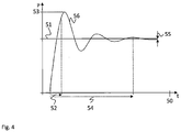
- Fig .4 shows a step response of the feedback signal 56 after initially driving e.g. the induction coil 6 or the coil 23, respectively.
- the feedback signal 56 does not linearly rise until it reaches the target or expected feedback signal 51. Instead, the feedback signal 56 overshoots the expected feedback signal 51 by an overshoot value 53 after a certain rise time 52.
- the rise time 52 in Fig. 4 is only exemplarily measured after the feedback signal 56 reaches 10% of the maximum or overshoot value 53 until the feedback signal 56 reaches 90% of the maximum or overshoot value 53. It is understood that the raise time can be defined differently in other embodiments.
- the settling time 54 of the feedback signal 56 is further shown.
- the settling time 54 refers to the time, which the feedback signal 56 takes to settle into a predetermined corridor or interval.
- the difference between the final value of the feedback signal 56 and the expected feedback signal 51 is shown as steady state error 55.
- the controller 7, 27 will calculate the new first threshold value 40, 41 based on the division of the initial first threshold value multiplied by the steady state error 55 and multiplied by a first constant K1 and the sum of a second constant K2 multiplied by the rise time 52 and multiplied by the overshoot value 53 and a third constant K3 multiplied by the settling time 54.
- C is the newly calculated first threshold value 40, 41, which is used in further operation of the induction coil 6.
- controller 7, 27 will calculate the second threshold value 42, 43 based on the division of the initial second threshold value multiplied by the steady state error 55 and multiplied by the first constant K1 and the sum of the second constant K2 multiplied by the rise time 52 and multiplied by the overshoot value 53 and the third constant K3 multiplied by the settling time 54.
- D is the newly calculated second threshold value 42, 43, which is used in further operation of the induction coil 6.
- Fig. 5 shows a flow diagram of a method for controlling an induction cooker 2, 20.
- the method comprises in step S1 controllably driving an induction coil 6 of the induction cooker 2, 20 with a power signal 5 of a configurable operating frequency, which is higher than a first initial threshold value and lower than a second initial threshold value.
- a feedback signal 10, 30, 56 is measured at the induction coil 6.
- the first threshold value 40, 41 and the second threshold value 42, 43 are adapted based on the feedback signal 10, 30, 56, which is measured in a predetermined time period 50 after application of the power signal 5.
- the step of adapting S3 can e.g. comprise comparing the measured feedback signal 10, 30, 56 in the predetermined time period 50 after application of the power signal 5 to a predetermined expected feedback signal 51, i.e. the step response.
- the first threshold value 40, 41 and the second threshold value 42, 43 can then be determined based on a rise time 52 of the measured feedback signal 10, 30, 56, and/or an overshoot value 53 of the measured feedback signal 10, 30, 56, and/or a settling time 54 of the measured feedback signal 10, 30, 56, and/or a steady state error 55 of the measured feedback signal 10, 30, 56.
- the first threshold value 40, 41 can e.g. be calculated based on the division of the initial first threshold value 40, 41 multiplied by the steady state error 55 and multiplied by a first constant K1 and the sum of a second constant K2 multiplied by the rise time 52 and multiplied by the overshoot value 53 and a third constant K3 multiplied by the settling time 54.
- the second threshold value 42, 43 can be calculated based on the division of the initial second threshold value 42, 43 multiplied by the steady state error 55 and multiplied by a first constant K1 and the sum of a second constant K2 multiplied by the rise time 52 and multiplied by the overshoot value 53 and a third constant K3 multiplied by the settling time 54.
- C is the newly calculated first threshold value 40, 41, which is used in further operation of the induction coil 6.
- D is the newly calculated second threshold value 42, 43, which is used in further operation of the induction coil 6.
- Fig. 6 shows a flow diagram of another method for controlling an induction cooker 2, 20.
- Fig. 6 Prior to driving S1, measuring S2, and adapting S3, the method in Fig. 6 comprises steps S4 and S5, which serve to detect if a cooking vessel 3, 25, 46, 47 is present over the induction coil 6.
- Step S4 comprises driving the induction coil 6 with a power signal 5 of a predetermined operating frequency.
- the presence of a cooking vessel 3, 25, 46, 47 is then determined in step S5 if the feedback signal 10. 30, 56 is equal to or exceeds a third threshold value.
- Decision D1 branches to the steps S1 - S3 only after the presence of a cooking vessel 3, 25, 46, 47 is determined in step S5. Otherwise, decision D1 branches back to step S4.
- step S6 comprises driving S6 the induction coil 6 based on the adapted first threshold value 40, 41 and second threshold value 42, 43.
- step S6 While the induction coil 6 is driven based on the adapted first threshold value 40, 41 and second threshold value 42, 43, it is further supervised if the cooking vessel 3, 25, 46, 47 is still present over the induction coil 6. Decision D2 returns to step S6 if the cooking vessel 3, 25, 46, 47 is present. Otherwise, decision D2 branches to step S7, where operation of the induction coil 6 is stopped.
- the present invention provides a control device (1) for an induction cooker (2, 20), the control device (1) comprising a driving circuit (4, 26) configured to controllably drive an induction coil (6) of the induction cooker (2, 20), a controller (7, 27) coupled to the driving circuit (4, 26) and configured to control the driving circuit (4, 26) with a control signal (8, 28) to drive the induction coil (6) with a power signal (5) of a configurable operating frequency, which is higher than a first initial threshold value and lower than a second initial threshold value, and a first measurement device (9, 29) configured to measure a feedback signal (10, 30, 56) at the induction coil (6) and provide the measured feedback signal (10, 30, 56) to the controller (7, 27).
- a driving circuit (4, 26) configured to controllably drive an induction coil (6) of the induction cooker (2, 20)
- a controller (7, 27) coupled to the driving circuit (4, 26) and configured to control the driving circuit (4, 26) with a control signal (8, 28) to drive the induction coil
- the controller (7, 27) is configured to adapt the first threshold value (40, 41) and the second threshold value (42, 43) based on the feedback signal (10, 30, 56), which is measured in a predetermined time period (50) after application of the power signal (5).
- the present invention further provides a respective method and an induction cooker.
Abstract
Description
- The invention relates to a control device and a control method for an induction cooker. Further, the present invention refers to a respective induction cooker.
- Although applicable to any system that uses energy transfer via induction to heat an element, the present invention will be mainly described in combination with induction cookers.
- Induction cookers are usually used to heat cooking vessels by magnetic induction. Usually a high frequency power signal is provided to an induction coil. This generates a magnetic field around the induction coil, which is magnetically coupled to a conductive cooking vessel, such as a pan, placed over the induction coil. The magnetic field then generates eddy currents in the cooking vessel, causing the cooking vessel to heat.
- In particular, the output power of the induction coil is a function of the power signal input, the coil inductance, the resistance of the cooking vessel, and the resonance frequency of the system. In known induction cookers, the induction coil is usually driven with a power signal at the resonance frequency of the system. The closer the system is driven to its resonance frequency, the more power can be delivered to the system. However, it is difficult to accurately measure the resonance frequency.
- Accordingly, there is a need for an improved power control in induction cookers.
- The present invention provides a control device with the features of
claim 1, a control method with the features ofclaim 8, and an induction cooker with the features of claim 15. - Accordingly a control device for an induction cooker comprises a driving circuit configured to controllably drive an induction coil of the induction cooker, a controller coupled to the driving circuit and configured to control the driving circuit with a control signal to drive the induction coil with a power signal of a configurable operating frequency, which is higher than a first initial threshold value and lower than a second initial threshold value, and a first measurement device configured to measure a feedback signal, e.g. a current signal or a voltage signal, at the induction coil and provide the measured feedback signal to the controller. The controller is configured to adapt the first threshold value and the second threshold value based on the feedback signal, which is measured in a predetermined time period after application of the power signal.
- Further, a control method for controlling an induction cooker comprises the steps of controllably driving an induction coil of the induction cooker with a power signal of a configurable operating frequency, which is higher than a first initial threshold value and lower than a second initial threshold value, measuring a feedback signal, e.g. a current signal or a voltage signal or a power signal, at the induction coil, and adapting the first threshold value and the second threshold value based on the feedback signal, which is measured in a predetermined time period after application of the power signal.
- Finally, an induction cooker comprises an induction coil, and a control device according to the present invention.
- Induction cookers usually use a fixed operating frequency range for the power signal, which drives the induction coils. The fixed operating frequency range usually starts at the resonance frequency of the induction coil and ends at a safety limit frequency. The maximum power is transferred to the cooking vessel at the resonance frequency of the system of induction coil and cooking vessel. Increasing the frequency will lower the transferred energy. However, at increased frequencies, the impedance of the induction coil will fall and the current through the induction coil will raise. Therefore, a maximum frequency is defined, which is not surpassed.
- Further, the effect a cooking vessel has on the input impedance and the resonance frequency of the induction coil can be taken into account when selecting the fixed frequency range. The operating frequency range can e.g. be selected for a virtual idealized or standardized cooking vessel, which represents an average of the existing cooking vessels. Objects, which are placed over the induction coil to cook, like e.g. pans or pots, will be referred to as cooking vessels throughout this description.
- The present invention is based on the knowledge that the ideal operating frequency range of the power signal depends on not only the position of a cooking vessel in relation to the induction coil, i.e. the presence or absence and the coverage ratio, but also on the material, which the cooking vessel is made of.
- However, if the ideal operating frequency range is determined by the material, which the cooking vessel is made of, one single fixed operating frequency range cannot provide the best performance with all cooking vessels.
- The present invention uses this knowledge and provides an adaptive operating frequency range, i.e. variable first and second threshold values. The operating frequency range can therefore be adapted to different cooking vessels, i.e. different materials used in cooking vessels.
- The initial first and second threshold values can be predetermined and e.g. be selected to be suitable for the majority of cooking vessels. The initial first and second threshold values can therefore also be selected based on the above-mentioned virtual idealized or standardized cooking vessel, which represents an average of the existing cooking vessels.
- In order to adapt the first and second threshold values the present invention does not rely e.g. on a measurement of the resonance frequency, but analyses the feedback signal in a predetermined time period after the power signal is applied. This can also be seen as analyzing a step response of the induction coil to the application of the power signal. The predetermined time period can e.g. be defined as a time period, which is long enough to accommodate the relevant section of the feedback signal for any possible cooking vessel. The predetermined time period can e.g. be experimentally determined, by measuring the step response of the induction coil with a plurality of different cooking vessels and measuring the settling time. The settling time is the time the feedback signal takes to come to a constant value or nearly constant value, i.e. within a predetermined signal range. The feedback signal can e.g. be in the form of a measured current through the induction coil. In the present patent application, the term induction coil can also refer to the resonant unit comprising the induction coil and a respective capacitor in parallel to the induction coil.
- Analyzing the step response of the induction coil when the power signal is applied reveals detailed information about the resonant circuit of induction coil and cooking vessel, i.e. about the cooking vessel's properties and influences on the induction coil.
- Further embodiments of the present invention are subject of the further subclaims and of the following description, referring to the drawings.
- In one embodiment, the controller can be configured to control the driving circuit to drive the induction coil with a power signal of a predetermined operating frequency. Further, the controller can be configured to determine the presence of a cooking vessel if the feedback signal is equal to or exceeds a third threshold value, wherein the controller is configured to adapt the first threshold value and the second threshold value after it determined the presence of a cooking vessel. The third threshold value can be empirically or experimentally predetermined as a value, which is reached only if a cooking vessel is at least partially in reach of the induction coil. The term "in reach" in this case means that electrical energy is at least partially transferred between the induction coil and the cooking vessel.
- Different induction coils with different sizes, i.e. with different nominal power levels, can be used in induction cookers. The feedback signal depends on the power level of the respective coil. If e.g. the induction coils work efficiently with a nominal power of 1600 Watt. The target can e.g. be to drive the coil when the bottom of the cooking vessel covers 50% of the induction coil. This means that the induction cooker starts heating the cooking vessel only if the bottom of the cooking vessel covers 50% of the induction coil or more. This means that the third threshold value would represent 50% of the nominal power of the induction coil, in the above example about 800 Watt (1600 * 50%).
- Detecting the presence of the cooking vessel allows determining the point in time at which the first and second threshold values should be determined. I.e. the step response of the induction coil will only be determined if a cooking vessel is present over the induction coil.
- In one embodiment, the controller can be configured to compare the measured feedback signal in the predetermined time period after application of the power signal to a predetermined expected or target feedback signal. Further, the controller can be configured to determine the first threshold value and the second threshold value based on a rise time of the measured feedback signal, and/or an overshoot value of the measured feedback signal, and/or a settling time of the measured feedback signal, and/or a steady state error of the measured feedback signal. The expected or target feedback signal can be provided in the form of a constant value. The expected target feedback signal represents the nominal power of the induction coil, e.g. 1600 Watt.
- The rise time refers to the time the measured feedback signal takes to rise to its maximum value after the power signal is applied. The overshoot value refers to the difference between the expected or target feedback signal and the maximum value of the feedback signal. The settling time refers to the time the measured feedback signal takes to reach a constant value after the power signal is applied. Finally, the steady state error refers to the difference between the constant value of the measured feedback signal and the expected or target feedback signal.
- In one embodiment, the controller can be configured to calculate the first threshold value based on the division of the initial first threshold value multiplied by the steady state error and multiplied by a first constant and the sum of a second constant multiplied by the rise time and multiplied by the overshoot value and a third constant multiplied by the settling time.
- The corresponding formula would be:

- Wherein A is the initial first threshold value and C is the newly calculated first threshold value, which is used in further operation of the induction coil.
- In one embodiment, the controller can be configured to calculate the second threshold value based on the division of the initial second threshold value multiplied by the steady state error and multiplied by a first constant and the sum of a second constant multiplied by the rise time and multiplied by the overshoot value and a third constant multiplied by the settling time.
- The corresponding formula would be:

- Wherein B is the initial second threshold value D is the newly calculated second threshold value, which is used in further operation of the induction coil.
- In one embodiment, the constants K1 - K3 can be experimentally defined. The respective mathematical formulas would be:


- Without the present invention, T0 should be "1" to keep the operation range constant. Therefore, T1 + T2 = 1.
- It is further assumed that T1 and T2 should be "1", T3 and T4 should be "0.5".
- Consequently:


- For a stable system, the steady_state_error should be %5 or lower of the target feedback signal. If for example the target feedback signal represents 1600 Watt or a corresponding current value then a worst-case steady_state_error should be 80 Watt or the corresponding current value.
- Consequently K1 would be:

- It is further assumed that the standard rise time is about 100ms, nevertheless other rise times are possible depending on the exact dimensions of the induction coil and the driving circuit. Further, the system may have an overvoltage protection. This protection is activated if the feedback signal is %25 higher than target feedback signal, i.e. 25% higher than the nominal power of the induction coil. If e.g. the target feedback signal represents 1600 Watt the protection limit is 1600 Watt + 25% = 2000Watt. The over voltage should therefore be 2000Watt - 1600Watt = 400Watt at the maximum.

- Also, a rise time of 100ms can be assumed and it can further be assumed that the system has an over power protection. This protection is activated if the feedback signal is 25% higher than the target feedback signal. If e.g. the target feedback signal is 1600 Watt the protection limit is 1600 Watt + 25% = 2000 Watt. Then the over shoot should be 2000 Watt -1600 Watt = 400 Watt.

- Either way, if the system comprises an overvoltage protection or an overpower protection, the result for K2 is the same.
- A final assumption can be that the settling time is 1s* W. Then

- Consequently, K1, K2 and K3 can be defined as:


- X, Y ,Z and W are parameters which depend on the size of the induction coil, glass types over the coil, the mechanical structure of induction cooker etc. These values can e.g. be experimentally determined after the hardware design and the mechanical design of the induction cooker is complete. The values of X,Y,Z and W can e.g. be varied until the required system performance is achieved.
- Exemplary values can e.g. be


- The above assumptions and examples refer to an induction coil with 1600 Watt nominal power and can further be varied depending on the coil power, glass types over the coil, the mechanical structure of cooker and the like.
- In one embodiment, the control device can comprise a control algorithm, which can be configured to drive the induction coil based on the adapted first threshold and second threshold, wherein the controller is configured to stop operation of the induction coil if the measured feedback signal drops below a fourth threshold value while driving the induction coil. The fourth threshold value is a lower limit for the measured feedback signal, which, as the third threshold value, can be empirically or experimentally predetermined as a value, which is reached only if a cooking vessel is at least partially in reach of the induction coil. In contrast to the third threshold value, the fourth threshold value is used when the induction coil is operated with other than the first and second threshold values.
- The fourth threshold value can e.g. be the same as the third threshold value.
- For a more complete understanding of the present invention and advantages thereof, reference is now made to the following description taken in conjunction with the accompanying drawings. The invention is explained in more detail below using exemplary embodiments, which are specified in the schematic figures of the drawings, in which:
- Fig. 1
- shows a block diagram of an embodiment of a control device according to the present invention in an embodiment of an induction cooker according to the present invention;
- Fig. 2
- shows a block diagram of another embodiment of induction cooker according to the present invention;
- Fig. 3
- shows a diagram with embodiments of first and second threshold values for different cooking vessels;
- Fig. 4
- shows a diagram with an embodiment of a measured feedback signal;
- Fig. 5
- shows a flow diagram of an embodiment of a method according to the present invention; and
- Fig. 6
- shows a flow diagram of another embodiment of a method according to the present invention.
- In the figures like reference signs denote like elements unless stated otherwise.
- In
Fig. 1 acontrol device 1 is installed in aninduction cooker 2, which is used to heat acooking vessel 3. Thecontrol device 1 comprises a drivingcircuit 4, which provides apower signal 5 to aninduction coil 6 of theinduction cooker 2. It is understood, that theinduction coil 6 is only shown schematically and can comprise further elements, like e.g. parallel capacitors. - Electrical power must be transferred from the
induction coil 6 to thecooking vessel 3 to heat up thecooking vessel 3. Therefore, the drivingcircuit 4 is controlled bycontroller 7 viacontrol signal 8 to operate thepower signal 5 at a configurable operating frequency, which is higher than a first initial threshold value and lower than a second initial threshold value. This implies that thepower signal 5 is a changing signal with a changing amplitude. The such driveninduction coil 6 will therefore generate a magnetic field, which in turn will induce eddy currents in thecooking vessel 3. Because of the electrical resistance of the material of thecooking vessel 3, the eddy currents will heat up thecooking vessel 3. - The
controller 7 is further coupled to ameasurement device 9, which will measure the current through theinduction coil 6, i.e. the current transported in thepower signal 5, and provide arespective feedback signal 10. Based on thefeedback signal 10, thecontroller 7 determines the electrical power, which is provided to theinduction coil 6, and with thecontrol signal 8 controls the frequency of thepower signal 5. - The first threshold value for the frequency can e.g. be the resonance frequency of the
induction coil 6 and thecooking vessel 3, i.e. the resonance frequency of the coupled system consisting ofinduction coil 6 and thecooking vessel 3. The second threshold value can e.g. be a maximum allowed frequency for the respective system. When the frequency is higher than the resonance frequency of the system, the impedance of the system will fall, therefore the current will rise. The second threshold value will therefore limit the maximum current through system of theinduction coil 6 and thecooking vessel 3. - The initial first and second threshold values can e.g. be determined based on a virtual idealized or
standardized cooking vessel 3, which represents an average of the existingcooking vessels 3. - Nevertheless, a wide variety of
cooking vessels 3 exist. The resonance frequency of the system ofinduction coil 6 andcooking vessel 3 also depends on the material and the geometry of thecooking vessel 3. The initial first and second threshold values will therefore not be valid for all types ofcooking vessel 3. This will lead to a reduced performance or efficiency of theinduction cooker 2. - Therefore, the
controller 7 will analyze thefeedback signal 10 in the start phase of theinduction coil 6, i.e. the step response of thefeedback signal 10 during a predetermined time period (seeFig. 4 ). Based on this step response thecontroller 7 will adapt the first and second threshold values accordingly. - The details of how the
controller 7 adapts the first and the second threshold values will be explained in conjunction withFig. 4 . - It is understood, that prior to adapting the first and second threshold values and driving the
induction coil 6 to heat acooking vessel 3, thecontroller 7 can perform a vessel detection. During the vessel detection, thecontroller 7 will identify if acooking vessel 3 is present over theinduction coil 6. Thecontroller 7 can e.g. control the drivingcircuit 4 to drive theinduction coil 6 with apower signal 5 of a predetermined operating frequency. Thecontroller 7 then determines the presence of acooking vessel 3 if thefeedback signal 10 is equal to or exceeds a third threshold value. - Further, after adapting the first and second threshold values and driving the
induction coil 6 to heat up thecooking vessel 3, thecontroller 7 can also continuously verify if thecooking vessel 3 is still present. If thecooking vessel 3 is not present any more, thecontroller 7 will stop the drivingcircuit 4 and therefore shut down theinduction cooker 2. -
Fig. 2 shows another possible schematic arrangement for aninduction cooker 20. - A
rectifier 22 can e.g. be connected to the mains power and provides a rectified electrical power. The rectified electrical power is provided to a parallel circuit of acoil 23 andcapacitor 24. These two elements,coil 23 andcapacitor 24, form the induction coil of theinduction cooker 20 and heat up acooking vessel 25. - The driving circuit is provided in the form of a
transistor 26, which can be controlled via thecontrol signal 28 by thecontroller 27. Thecontroller 27 therefore provides acontrol signal 28 with the frequency, which is required to drive thecoil 23. Ashunt resistor 29 provides thefeedback signal 30 to the controller via anamplifier 31. - The diagram of
Fig. 3 shows the output power of the drivingcircuit 4 with respect to the frequency of thepower signal 5 at different frequencies for twodifferent cooking vessels induction coil 6 with therespective cooking vessel circuit induction coil 6 with therespective cooking vessel - It can be seen, that for cooking
vessel 46 thefirst threshold 40 value is at first frequency and thesecond threshold value 42 at a second frequency. However, thefirst threshold value 41 for thecooking vessel 47 is at a frequency even higher than thesecond threshold value 42. That means that the frequency ranges of thecooking vessels - It is understood from
Fig. 3 that it is necessary to adapt the initial frequency range for driving theinduction coil 6 accordingly fordifferent cooking vessels 3. -
Fig .4 shows a step response of thefeedback signal 56 after initially driving e.g. theinduction coil 6 or thecoil 23, respectively. - It can be seen that the
feedback signal 56 does not linearly rise until it reaches the target or expectedfeedback signal 51. Instead, thefeedback signal 56 overshoots the expectedfeedback signal 51 by anovershoot value 53 after acertain rise time 52. Therise time 52 inFig. 4 is only exemplarily measured after thefeedback signal 56reaches 10% of the maximum orovershoot value 53 until thefeedback signal 56 reaches 90% of the maximum orovershoot value 53. It is understood that the raise time can be defined differently in other embodiments. - In the diagram, the
settling time 54 of thefeedback signal 56 is further shown. Thesettling time 54 refers to the time, which thefeedback signal 56 takes to settle into a predetermined corridor or interval. Finally, in the diagram, the difference between the final value of thefeedback signal 56 and the expectedfeedback signal 51 is shown as steady state error 55. - The
controller first threshold value rise time 52 and multiplied by theovershoot value 53 and a third constant K3 multiplied by thesettling time 54. - The corresponding formula would be:

- Wherein C is the newly calculated
first threshold value induction coil 6. - Further, the
controller second threshold value rise time 52 and multiplied by theovershoot value 53 and the third constant K3 multiplied by thesettling time 54. - The corresponding formula would be:

- Wherein D is the newly calculated
second threshold value induction coil 6. - The constants K1 - K3 can be defined as already indicated above. Exact values can e.g. be K1 = 0.0125, K2 = 0.000125, and K3 = 0.5.
-
Fig. 5 shows a flow diagram of a method for controlling aninduction cooker induction coil 6 of theinduction cooker power signal 5 of a configurable operating frequency, which is higher than a first initial threshold value and lower than a second initial threshold value. In step S2 afeedback signal induction coil 6. Finally, in step S3 thefirst threshold value second threshold value feedback signal predetermined time period 50 after application of thepower signal 5. - The step of adapting S3 can e.g. comprise comparing the measured
feedback signal predetermined time period 50 after application of thepower signal 5 to a predetermined expectedfeedback signal 51, i.e. the step response. - The
first threshold value second threshold value rise time 52 of the measuredfeedback signal overshoot value 53 of the measuredfeedback signal settling time 54 of the measuredfeedback signal feedback signal - The
first threshold value first threshold value rise time 52 and multiplied by theovershoot value 53 and a third constant K3 multiplied by thesettling time 54. - The
second threshold value second threshold value rise time 52 and multiplied by theovershoot value 53 and a third constant K3 multiplied by thesettling time 54. - The corresponding formula for the
first threshold value 
- Wherein C is the newly calculated
first threshold value induction coil 6. - The corresponding formula for the
second threshold value 
- Wherein D is the newly calculated
second threshold value induction coil 6. -
Fig. 6 shows a flow diagram of another method for controlling aninduction cooker - Prior to driving S1, measuring S2, and adapting S3, the method in
Fig. 6 comprises steps S4 and S5, which serve to detect if acooking vessel induction coil 6. - Step S4 comprises driving the
induction coil 6 with apower signal 5 of a predetermined operating frequency. The presence of acooking vessel feedback signal 10. 30, 56 is equal to or exceeds a third threshold value. Decision D1 branches to the steps S1 - S3 only after the presence of acooking vessel - If a
cooking vessel induction coil 6 based on the adaptedfirst threshold value second threshold value - While the
induction coil 6 is driven based on the adaptedfirst threshold value second threshold value cooking vessel induction coil 6. Decision D2 returns to step S6 if thecooking vessel induction coil 6 is stopped. - For detecting if the
cooking vessel feedback signal induction coil 6. - Although specific embodiments have been illustrated and described herein, it will be appreciated by those of ordinary skill in the art that a variety of alternate and/or equivalent implementations exist. It should be appreciated that the exemplary embodiment or exemplary embodiments are only examples, and are not intended to limit the scope, applicability, or configuration in any way. Rather, the foregoing summary and detailed description will provide those skilled in the art with a convenient road map for implementing at least one exemplary embodiment, it being understood that various changes may be made in the function and arrangement of elements described in an exemplary embodiment without departing from the scope as set forth in the appended claims and their legal equivalents. Generally, this application is intended to cover any adaptations or variations of the specific embodiments discussed herein.
- The present invention provides a control device (1) for an induction cooker (2, 20), the control device (1) comprising a driving circuit (4, 26) configured to controllably drive an induction coil (6) of the induction cooker (2, 20), a controller (7, 27) coupled to the driving circuit (4, 26) and configured to control the driving circuit (4, 26) with a control signal (8, 28) to drive the induction coil (6) with a power signal (5) of a configurable operating frequency, which is higher than a first initial threshold value and lower than a second initial threshold value, and a first measurement device (9, 29) configured to measure a feedback signal (10, 30, 56) at the induction coil (6) and provide the measured feedback signal (10, 30, 56) to the controller (7, 27). The controller (7, 27) is configured to adapt the first threshold value (40, 41) and the second threshold value (42, 43) based on the feedback signal (10, 30, 56), which is measured in a predetermined time period (50) after application of the power signal (5). The present invention further provides a respective method and an induction cooker.
-
- 1
- control device
- 2, 20
- induction cooker
- 3, 25, 46, 47
- cooking vessel
- 4, 26
- driving circuit
- 5
- power signal
- 6
- induction coil
- 7, 27
- controller
- 8, 28
- control signal
- 9, 29
- measurement device
- 10, 30, 56
- feedback signal
- 22
- rectifier
- 23
- coil
- 24
- capacitor
- 31
- amplifier
- 32
- ground
- 40, 41
- first threshold value
- 42, 43
- second threshold value
- 44, 45
- human hearing limit
- 50
- predetermined time period
- 51
- expected feedback signal
- 52
- rise time
- 53
- overshoot value
- 54
- settling time
- 55
- steady state error
- S1 - S7
- method steps
Claims (15)
- Control device (1) for an induction cooker (2, 20), the control device (1) comprising:a driving circuit (4, 26) configured to controllably drive an induction coil (6) of the induction cooker (2, 20) with a power signal (5),a controller (7, 27) coupled to the driving circuit (4, 26) and configured to control the driving circuit (4, 26) with a control signal (8, 28) to drive the induction coil (6) with the power signal (5) of a configurable operating frequency, which is higher than a first initial threshold value and lower than a second initial threshold value, anda first measurement device (9, 29) configured to measure a feedback signal (10, 30, 56) at the induction coil (6) and provide the measured feedback signal (10, 30, 56) to the controller (7, 27),wherein the controller (7, 27) is configured to adapt the first threshold value (40, 41) and the second threshold value (42, 43) based on the feedback signal (10, 30, 56), which is measured in a predetermined time period (50) after application of the power signal (5).
- Control device (1) according to claim 1, wherein the controller (7, 27) is configured to control the driving circuit (4, 26) to drive the induction coil (6) with a power signal (5) of a predetermined operating frequency and to determine the presence of a cooking vessel (3, 25, 46, 47) if the feedback signal (10, 30, 56) is equal to or exceeds a third threshold value, wherein the controller (7, 27) is configured to adapt the first threshold value (40, 41) and the second threshold value (42, 43) after it determined the presence of a cooking vessel (3, 25, 46, 47).
- Control device (1) according to any one of the preceding claims, wherein the controller (7, 27) is configured to compare the measured feedback signal (10, 30, 56) in the predetermined time period (50) after application of the power signal (5) to a predetermined expected feedback signal (51) and determine the first threshold value (40, 41) and the second threshold value (42, 43) based on a rise time (52) of the measured feedback signal (10, 30, 56), and/or an overshoot value (53) of the measured feedback signal (10, 30, 56), and/or a settling time (54) of the measured feedback signal (10, 30, 56), and/or a steady state error (55) of the measured feedback signal (10, 30, 56).
- Control device (1) according to claim 3, wherein the controller (7, 27) is configured to calculate the first threshold value (40, 41) based on the division of the initial first threshold value (40, 41) multiplied by the steady state error (55) and multiplied by a first constant and the sum of a second constant multiplied by the rise time (52) and multiplied by the overshoot value (53) and a third constant multiplied by the settling time (54).
- Control device (1) according to any one of claims 3 and 4, wherein the controller (7, 27) is configured to calculate the second threshold value (42, 43) based on the division of the initial second threshold value (42, 43) multiplied by the steady state error (55) and multiplied by a first constant and the sum of a second constant multiplied by the rise time (52) and multiplied by the overshoot value (53) and a third constant multiplied by the settling time (54).
- Control device (1) according to claims 4 and 5, wherein the first constant is defined as 0.0125, and wherein the second constant is defined as 0.000125, and wherein the third constant is defined as 0.5.
- Control device (1) according to any one of the preceding claims, wherein the control device (1) comprises a control algorithm, which is configured drive the induction coil (6) based on the adapted first threshold value (40, 41) and second threshold value (42, 43), wherein the controller (7, 27) is configured to stop operation of the induction coil (6) if the measured feedback signal (10, 30, 56) drops below a fourth threshold value while driving the induction coil (6).
- Control method for controlling an induction cooker (2, 20), the control method comprising the steps of:controllably (S1) driving an induction coil (6) of the induction cooker (2, 20) with a power signal (5) of a configurable operating frequency, which is higher than a first initial threshold value and lower than a second initial threshold value,measuring (S2) a feedback signal (10, 30, 56) at the induction coil (6), andadapting (S3) the first threshold value (40, 41) and the second threshold value (42, 43) based on the feedback signal (10, 30, 56), which is measured in a predetermined time period (50) after application of the power signal (5).
- Control method according to claim 8, further comprising driving (S4) the induction coil (6) with a power signal (5) of a predetermined operating frequency, and determining (S5) the presence of a cooking vessel (3, 25, 46, 47) if the feedback signal (10, 30, 56) is equal to or exceeds a third threshold value, and adapting (S3) the first threshold value (40, 41) and the second threshold value (42, 43) after the presence of a cooking vessel (3, 25, 46, 47) is determined.
- Control method according to any one of the preceding claims 8 and 9, wherein adapting (S3) comprises comparing the measured feedback signal (10, 30, 56) in the predetermined time period (50) after application of the power signal (5) to a predetermined expected feedback signal (51), and determining the first threshold value (40, 41) and the second threshold value (42, 43) based on a rise time (52) of the measured feedback signal (10, 30, 56), and/or an overshoot value (53) of the measured feedback signal (10, 30, 56), and/or a settling time (54) of the measured feedback signal (10, 30, 56), and/or a steady state error (55) of the measured feedback signal (10, 30, 56).
- Control method according to claim 10, wherein adapting (S3) further comprises calculating the first threshold value (40, 41) based on the division of the initial first threshold value (40, 41) multiplied by the steady state error (55) and multiplied by a first constant and the sum of a second constant multiplied by the rise time (52) and multiplied by the overshoot value (53) and a third constant multiplied by the settling time (54).
- Control method according to any one of claims 10 and 11, wherein adapting (S3) further comprises calculating the second threshold value (42, 43) based on the division of the initial second threshold value (42, 43) multiplied by the steady state error (55) and multiplied by a first constant and the sum of a second constant multiplied by the rise time (52) and multiplied by the overshoot value (53) and a third constant multiplied by the settling time (54).
- Control method according to any one of claims 11 and 12, wherein the first constant is defined as 0.0125, and wherein the second constant is defined as 0.000125, and wherein the third constant is defined as 0.5.
- Control method according to any one of the preceding claims 8 to 13, further comprising driving (S6) the induction coil (6) based on the adapted first threshold (40, 41) value and second threshold value (42, 43), wherein operation of the induction coil (6) is stopped (S7) if the measured feedback signal (10, 30, 56) drops below a fourth threshold value while driving the induction coil (6).
- Induction cooker (2, 20), comprising
an induction coil (6), and
a control device (1) according to any one of claims 1 - 7.
Priority Applications (2)
| Application Number | Priority Date | Filing Date | Title |
|---|---|---|---|
| EP16187048.0A EP3291641B1 (en) | 2016-09-02 | 2016-09-02 | Control device, control method, and induction cooker |
| TR2017/02391A TR201702391A2 (en) | 2016-09-02 | 2017-02-17 | Control device, control method, and induction cooker. |
Applications Claiming Priority (1)
| Application Number | Priority Date | Filing Date | Title |
|---|---|---|---|
| EP16187048.0A EP3291641B1 (en) | 2016-09-02 | 2016-09-02 | Control device, control method, and induction cooker |
Publications (2)
| Publication Number | Publication Date |
|---|---|
| EP3291641A1 true EP3291641A1 (en) | 2018-03-07 |
| EP3291641B1 EP3291641B1 (en) | 2019-04-10 |
Family
ID=56853532
Family Applications (1)
| Application Number | Title | Priority Date | Filing Date |
|---|---|---|---|
| EP16187048.0A Active EP3291641B1 (en) | 2016-09-02 | 2016-09-02 | Control device, control method, and induction cooker |
Country Status (2)
| Country | Link |
|---|---|
| EP (1) | EP3291641B1 (en) |
| TR (1) | TR201702391A2 (en) |
Cited By (1)
| Publication number | Priority date | Publication date | Assignee | Title |
|---|---|---|---|---|
| CN110446286A (en) * | 2018-05-03 | 2019-11-12 | 佛山市顺德区美的电热电器制造有限公司 | Electromagnetic heating cooking utensil and its control method, device |
Citations (3)
| Publication number | Priority date | Publication date | Assignee | Title |
|---|---|---|---|---|
| JP2002075616A (en) * | 2000-09-04 | 2002-03-15 | Fuji Electric Co Ltd | Control device of power supply for electromagnetic cooker |
| JP2011108430A (en) * | 2009-11-16 | 2011-06-02 | Panasonic Corp | Induction heating cooker |
| EP2914060A1 (en) * | 2012-10-25 | 2015-09-02 | Panasonic Intellectual Property Management Co., Ltd. | Induction heating device |
-
2016
- 2016-09-02 EP EP16187048.0A patent/EP3291641B1/en active Active
-
2017
- 2017-02-17 TR TR2017/02391A patent/TR201702391A2/en unknown
Patent Citations (3)
| Publication number | Priority date | Publication date | Assignee | Title |
|---|---|---|---|---|
| JP2002075616A (en) * | 2000-09-04 | 2002-03-15 | Fuji Electric Co Ltd | Control device of power supply for electromagnetic cooker |
| JP2011108430A (en) * | 2009-11-16 | 2011-06-02 | Panasonic Corp | Induction heating cooker |
| EP2914060A1 (en) * | 2012-10-25 | 2015-09-02 | Panasonic Intellectual Property Management Co., Ltd. | Induction heating device |
Cited By (1)
| Publication number | Priority date | Publication date | Assignee | Title |
|---|---|---|---|---|
| CN110446286A (en) * | 2018-05-03 | 2019-11-12 | 佛山市顺德区美的电热电器制造有限公司 | Electromagnetic heating cooking utensil and its control method, device |
Also Published As
| Publication number | Publication date |
|---|---|
| TR201702391A2 (en) | 2018-03-21 |
| EP3291641B1 (en) | 2019-04-10 |
Similar Documents
| Publication | Publication Date | Title |
|---|---|---|
| US7176424B2 (en) | Induction heating cooking apparatus and method for operating the same | |
| US20120285948A1 (en) | System and method for detecting vessel presence and circuit resonance for an induction heating apparatus | |
| EP3560279B1 (en) | Cooking appliance | |
| EP2854477B1 (en) | A method and device for determining the suitability of a cookware for the corresponding induction coil of an induction cooking hob | |
| JP4258737B2 (en) | Induction heating cooker and induction heating cooking method | |
| EP2876973B1 (en) | A method and a device for checking an ideal position of a cooking pot above an induction coil of an induction cooking hob | |
| WO2013064331A1 (en) | An induction heating cooker | |
| KR101905662B1 (en) | Induction Heating Cooker for Heating Magnetic and Non-magnetic Containers | |
| KR20190040843A (en) | Induction heating apparatus | |
| CN107112788B (en) | Method, circuit and article of manufacture for controlling wireless power transfer in response to controller circuit state | |
| CN106211394B (en) | Electromagnetic heating system and its switching tube open control device and method | |
| US20200323048A1 (en) | Induction heating apparatus | |
| EP3291641B1 (en) | Control device, control method, and induction cooker | |
| CN109716609B (en) | Method for phase-controlled excitation of a power transformer | |
| JP2014220108A (en) | Induction heating apparatus | |
| US20160095168A1 (en) | System and method for detecting vessel presence for an induction heating apparatus | |
| JP6342066B1 (en) | Power transmission equipment | |
| EP3582586A1 (en) | Method for controlling a cooking zone of an induction cooking hob | |
| WO2014037898A1 (en) | Procedure for the induction heating of industrial and domestic cookers with optimisation of the power supplied | |
| US9596721B2 (en) | Method for protecting switching elements in an induction heating system | |
| WO2014090868A1 (en) | An induction heating cooktop | |
| JP4406585B2 (en) | Induction voltage detection method and apparatus, and induction heating system | |
| EP3340737B1 (en) | Control device, control method, and induction cooker | |
| EP3383131A1 (en) | Inductive cooking device and method | |
| KR20210032666A (en) | An induction heating device having improved power control function |
Legal Events
| Date | Code | Title | Description |
|---|---|---|---|
| PUAI | Public reference made under article 153(3) epc to a published international application that has entered the european phase |
Free format text: ORIGINAL CODE: 0009012 |
|
| STAA | Information on the status of an ep patent application or granted ep patent |
Free format text: STATUS: THE APPLICATION HAS BEEN PUBLISHED |
|
| AK | Designated contracting states |
Kind code of ref document: A1 Designated state(s): AL AT BE BG CH CY CZ DE DK EE ES FI FR GB GR HR HU IE IS IT LI LT LU LV MC MK MT NL NO PL PT RO RS SE SI SK SM TR |
|
| AX | Request for extension of the european patent |
Extension state: BA ME |
|
| STAA | Information on the status of an ep patent application or granted ep patent |
Free format text: STATUS: REQUEST FOR EXAMINATION WAS MADE |
|
| 17P | Request for examination filed |
Effective date: 20180904 |
|
| RBV | Designated contracting states (corrected) |
Designated state(s): AL AT BE BG CH CY CZ DE DK EE ES FI FR GB GR HR HU IE IS IT LI LT LU LV MC MK MT NL NO PL PT RO RS SE SI SK SM TR |
|
| GRAP | Despatch of communication of intention to grant a patent |
Free format text: ORIGINAL CODE: EPIDOSNIGR1 |
|
| STAA | Information on the status of an ep patent application or granted ep patent |
Free format text: STATUS: GRANT OF PATENT IS INTENDED |
|
| RIC1 | Information provided on ipc code assigned before grant |
Ipc: H05B 6/06 20060101AFI20181015BHEP |
|
| INTG | Intention to grant announced |
Effective date: 20181113 |
|
| GRAS | Grant fee paid |
Free format text: ORIGINAL CODE: EPIDOSNIGR3 |
|
| GRAA | (expected) grant |
Free format text: ORIGINAL CODE: 0009210 |
|
| STAA | Information on the status of an ep patent application or granted ep patent |
Free format text: STATUS: THE PATENT HAS BEEN GRANTED |
|
| AK | Designated contracting states |
Kind code of ref document: B1 Designated state(s): AL AT BE BG CH CY CZ DE DK EE ES FI FR GB GR HR HU IE IS IT LI LT LU LV MC MK MT NL NO PL PT RO RS SE SI SK SM TR |
|
| REG | Reference to a national code |
Ref country code: GB Ref legal event code: FG4D |
|
| REG | Reference to a national code |
Ref country code: CH Ref legal event code: EP Ref country code: AT Ref legal event code: REF Ref document number: 1120485 Country of ref document: AT Kind code of ref document: T Effective date: 20190415 |
|
| REG | Reference to a national code |
Ref country code: IE Ref legal event code: FG4D |
|
| REG | Reference to a national code |
Ref country code: DE Ref legal event code: R096 Ref document number: 602016012146 Country of ref document: DE |
|
| REG | Reference to a national code |
Ref country code: NL Ref legal event code: MP Effective date: 20190410 |
|
| REG | Reference to a national code |
Ref country code: LT Ref legal event code: MG4D |
|
| REG | Reference to a national code |
Ref country code: AT Ref legal event code: MK05 Ref document number: 1120485 Country of ref document: AT Kind code of ref document: T Effective date: 20190410 |
|
| PG25 | Lapsed in a contracting state [announced via postgrant information from national office to epo] |
Ref country code: NL Free format text: LAPSE BECAUSE OF FAILURE TO SUBMIT A TRANSLATION OF THE DESCRIPTION OR TO PAY THE FEE WITHIN THE PRESCRIBED TIME-LIMIT Effective date: 20190410 |
|
| PG25 | Lapsed in a contracting state [announced via postgrant information from national office to epo] |
Ref country code: AL Free format text: LAPSE BECAUSE OF FAILURE TO SUBMIT A TRANSLATION OF THE DESCRIPTION OR TO PAY THE FEE WITHIN THE PRESCRIBED TIME-LIMIT Effective date: 20190410 Ref country code: NO Free format text: LAPSE BECAUSE OF FAILURE TO SUBMIT A TRANSLATION OF THE DESCRIPTION OR TO PAY THE FEE WITHIN THE PRESCRIBED TIME-LIMIT Effective date: 20190710 Ref country code: ES Free format text: LAPSE BECAUSE OF FAILURE TO SUBMIT A TRANSLATION OF THE DESCRIPTION OR TO PAY THE FEE WITHIN THE PRESCRIBED TIME-LIMIT Effective date: 20190410 Ref country code: LT Free format text: LAPSE BECAUSE OF FAILURE TO SUBMIT A TRANSLATION OF THE DESCRIPTION OR TO PAY THE FEE WITHIN THE PRESCRIBED TIME-LIMIT Effective date: 20190410 Ref country code: HR Free format text: LAPSE BECAUSE OF FAILURE TO SUBMIT A TRANSLATION OF THE DESCRIPTION OR TO PAY THE FEE WITHIN THE PRESCRIBED TIME-LIMIT Effective date: 20190410 Ref country code: PT Free format text: LAPSE BECAUSE OF FAILURE TO SUBMIT A TRANSLATION OF THE DESCRIPTION OR TO PAY THE FEE WITHIN THE PRESCRIBED TIME-LIMIT Effective date: 20190910 Ref country code: SE Free format text: LAPSE BECAUSE OF FAILURE TO SUBMIT A TRANSLATION OF THE DESCRIPTION OR TO PAY THE FEE WITHIN THE PRESCRIBED TIME-LIMIT Effective date: 20190410 Ref country code: FI Free format text: LAPSE BECAUSE OF FAILURE TO SUBMIT A TRANSLATION OF THE DESCRIPTION OR TO PAY THE FEE WITHIN THE PRESCRIBED TIME-LIMIT Effective date: 20190410 |
|
| PG25 | Lapsed in a contracting state [announced via postgrant information from national office to epo] |
Ref country code: LV Free format text: LAPSE BECAUSE OF FAILURE TO SUBMIT A TRANSLATION OF THE DESCRIPTION OR TO PAY THE FEE WITHIN THE PRESCRIBED TIME-LIMIT Effective date: 20190410 Ref country code: PL Free format text: LAPSE BECAUSE OF FAILURE TO SUBMIT A TRANSLATION OF THE DESCRIPTION OR TO PAY THE FEE WITHIN THE PRESCRIBED TIME-LIMIT Effective date: 20190410 Ref country code: RS Free format text: LAPSE BECAUSE OF FAILURE TO SUBMIT A TRANSLATION OF THE DESCRIPTION OR TO PAY THE FEE WITHIN THE PRESCRIBED TIME-LIMIT Effective date: 20190410 Ref country code: BG Free format text: LAPSE BECAUSE OF FAILURE TO SUBMIT A TRANSLATION OF THE DESCRIPTION OR TO PAY THE FEE WITHIN THE PRESCRIBED TIME-LIMIT Effective date: 20190710 Ref country code: GR Free format text: LAPSE BECAUSE OF FAILURE TO SUBMIT A TRANSLATION OF THE DESCRIPTION OR TO PAY THE FEE WITHIN THE PRESCRIBED TIME-LIMIT Effective date: 20190711 |
|
| PG25 | Lapsed in a contracting state [announced via postgrant information from national office to epo] |
Ref country code: IS Free format text: LAPSE BECAUSE OF FAILURE TO SUBMIT A TRANSLATION OF THE DESCRIPTION OR TO PAY THE FEE WITHIN THE PRESCRIBED TIME-LIMIT Effective date: 20190810 Ref country code: AT Free format text: LAPSE BECAUSE OF FAILURE TO SUBMIT A TRANSLATION OF THE DESCRIPTION OR TO PAY THE FEE WITHIN THE PRESCRIBED TIME-LIMIT Effective date: 20190410 |
|
| REG | Reference to a national code |
Ref country code: DE Ref legal event code: R097 Ref document number: 602016012146 Country of ref document: DE |
|
| PG25 | Lapsed in a contracting state [announced via postgrant information from national office to epo] |
Ref country code: SK Free format text: LAPSE BECAUSE OF FAILURE TO SUBMIT A TRANSLATION OF THE DESCRIPTION OR TO PAY THE FEE WITHIN THE PRESCRIBED TIME-LIMIT Effective date: 20190410 Ref country code: EE Free format text: LAPSE BECAUSE OF FAILURE TO SUBMIT A TRANSLATION OF THE DESCRIPTION OR TO PAY THE FEE WITHIN THE PRESCRIBED TIME-LIMIT Effective date: 20190410 Ref country code: DK Free format text: LAPSE BECAUSE OF FAILURE TO SUBMIT A TRANSLATION OF THE DESCRIPTION OR TO PAY THE FEE WITHIN THE PRESCRIBED TIME-LIMIT Effective date: 20190410 Ref country code: RO Free format text: LAPSE BECAUSE OF FAILURE TO SUBMIT A TRANSLATION OF THE DESCRIPTION OR TO PAY THE FEE WITHIN THE PRESCRIBED TIME-LIMIT Effective date: 20190410 Ref country code: CZ Free format text: LAPSE BECAUSE OF FAILURE TO SUBMIT A TRANSLATION OF THE DESCRIPTION OR TO PAY THE FEE WITHIN THE PRESCRIBED TIME-LIMIT Effective date: 20190410 |
|
| PLBE | No opposition filed within time limit |
Free format text: ORIGINAL CODE: 0009261 |
|
| STAA | Information on the status of an ep patent application or granted ep patent |
Free format text: STATUS: NO OPPOSITION FILED WITHIN TIME LIMIT |
|
| PG25 | Lapsed in a contracting state [announced via postgrant information from national office to epo] |
Ref country code: SM Free format text: LAPSE BECAUSE OF FAILURE TO SUBMIT A TRANSLATION OF THE DESCRIPTION OR TO PAY THE FEE WITHIN THE PRESCRIBED TIME-LIMIT Effective date: 20190410 Ref country code: IT Free format text: LAPSE BECAUSE OF FAILURE TO SUBMIT A TRANSLATION OF THE DESCRIPTION OR TO PAY THE FEE WITHIN THE PRESCRIBED TIME-LIMIT Effective date: 20190410 |
|
| 26N | No opposition filed |
Effective date: 20200113 |
|
| PG25 | Lapsed in a contracting state [announced via postgrant information from national office to epo] |
Ref country code: SI Free format text: LAPSE BECAUSE OF FAILURE TO SUBMIT A TRANSLATION OF THE DESCRIPTION OR TO PAY THE FEE WITHIN THE PRESCRIBED TIME-LIMIT Effective date: 20190410 Ref country code: MC Free format text: LAPSE BECAUSE OF FAILURE TO SUBMIT A TRANSLATION OF THE DESCRIPTION OR TO PAY THE FEE WITHIN THE PRESCRIBED TIME-LIMIT Effective date: 20190410 |
|
| REG | Reference to a national code |
Ref country code: CH Ref legal event code: PL |
|
| PG25 | Lapsed in a contracting state [announced via postgrant information from national office to epo] |
Ref country code: CH Free format text: LAPSE BECAUSE OF NON-PAYMENT OF DUE FEES Effective date: 20190930 Ref country code: LI Free format text: LAPSE BECAUSE OF NON-PAYMENT OF DUE FEES Effective date: 20190930 Ref country code: IE Free format text: LAPSE BECAUSE OF NON-PAYMENT OF DUE FEES Effective date: 20190902 Ref country code: LU Free format text: LAPSE BECAUSE OF NON-PAYMENT OF DUE FEES Effective date: 20190902 |
|
| REG | Reference to a national code |
Ref country code: BE Ref legal event code: MM Effective date: 20190930 |
|
| PG25 | Lapsed in a contracting state [announced via postgrant information from national office to epo] |
Ref country code: BE Free format text: LAPSE BECAUSE OF NON-PAYMENT OF DUE FEES Effective date: 20190930 |
|
| PGFP | Annual fee paid to national office [announced via postgrant information from national office to epo] |
Ref country code: GB Payment date: 20200923 Year of fee payment: 5 Ref country code: DE Payment date: 20200924 Year of fee payment: 5 |
|
| PG25 | Lapsed in a contracting state [announced via postgrant information from national office to epo] |
Ref country code: CY Free format text: LAPSE BECAUSE OF FAILURE TO SUBMIT A TRANSLATION OF THE DESCRIPTION OR TO PAY THE FEE WITHIN THE PRESCRIBED TIME-LIMIT Effective date: 20190410 |
|
| PG25 | Lapsed in a contracting state [announced via postgrant information from national office to epo] |
Ref country code: HU Free format text: LAPSE BECAUSE OF FAILURE TO SUBMIT A TRANSLATION OF THE DESCRIPTION OR TO PAY THE FEE WITHIN THE PRESCRIBED TIME-LIMIT; INVALID AB INITIO Effective date: 20160902 Ref country code: FR Free format text: LAPSE BECAUSE OF NON-PAYMENT OF DUE FEES Effective date: 20190930 Ref country code: MT Free format text: LAPSE BECAUSE OF FAILURE TO SUBMIT A TRANSLATION OF THE DESCRIPTION OR TO PAY THE FEE WITHIN THE PRESCRIBED TIME-LIMIT Effective date: 20190410 |
|
| REG | Reference to a national code |
Ref country code: DE Ref legal event code: R119 Ref document number: 602016012146 Country of ref document: DE |
|
| GBPC | Gb: european patent ceased through non-payment of renewal fee |
Effective date: 20210902 |
|
| PG25 | Lapsed in a contracting state [announced via postgrant information from national office to epo] |
Ref country code: MK Free format text: LAPSE BECAUSE OF FAILURE TO SUBMIT A TRANSLATION OF THE DESCRIPTION OR TO PAY THE FEE WITHIN THE PRESCRIBED TIME-LIMIT Effective date: 20190410 |
|
| PG25 | Lapsed in a contracting state [announced via postgrant information from national office to epo] |
Ref country code: GB Free format text: LAPSE BECAUSE OF NON-PAYMENT OF DUE FEES Effective date: 20210902 Ref country code: DE Free format text: LAPSE BECAUSE OF NON-PAYMENT OF DUE FEES Effective date: 20220401 |
|
| PGFP | Annual fee paid to national office [announced via postgrant information from national office to epo] |
Ref country code: TR Payment date: 20230823 Year of fee payment: 8 |