EP3291414A2 - Moteur à réluctance commutée, à structure stratifiée axiale - Google Patents
Moteur à réluctance commutée, à structure stratifiée axiale Download PDFInfo
- Publication number
- EP3291414A2 EP3291414A2 EP17188284.8A EP17188284A EP3291414A2 EP 3291414 A2 EP3291414 A2 EP 3291414A2 EP 17188284 A EP17188284 A EP 17188284A EP 3291414 A2 EP3291414 A2 EP 3291414A2
- Authority
- EP
- European Patent Office
- Prior art keywords
- stator
- rotor
- switched reluctance
- reluctance motor
- laminate sheets
- Prior art date
- Legal status (The legal status is an assumption and is not a legal conclusion. Google has not performed a legal analysis and makes no representation as to the accuracy of the status listed.)
- Withdrawn
Links
Images


Classifications
-
- H—ELECTRICITY
- H02—GENERATION; CONVERSION OR DISTRIBUTION OF ELECTRIC POWER
- H02K—DYNAMO-ELECTRIC MACHINES
- H02K1/00—Details of the magnetic circuit
- H02K1/06—Details of the magnetic circuit characterised by the shape, form or construction
- H02K1/08—Salient poles
-
- H—ELECTRICITY
- H02—GENERATION; CONVERSION OR DISTRIBUTION OF ELECTRIC POWER
- H02K—DYNAMO-ELECTRIC MACHINES
- H02K1/00—Details of the magnetic circuit
- H02K1/06—Details of the magnetic circuit characterised by the shape, form or construction
- H02K1/12—Stationary parts of the magnetic circuit
- H02K1/14—Stator cores with salient poles
- H02K1/146—Stator cores with salient poles consisting of a generally annular yoke with salient poles
- H02K1/148—Sectional cores
-
- H—ELECTRICITY
- H02—GENERATION; CONVERSION OR DISTRIBUTION OF ELECTRIC POWER
- H02K—DYNAMO-ELECTRIC MACHINES
- H02K1/00—Details of the magnetic circuit
- H02K1/06—Details of the magnetic circuit characterised by the shape, form or construction
- H02K1/22—Rotating parts of the magnetic circuit
- H02K1/24—Rotor cores with salient poles ; Variable reluctance rotors
- H02K1/246—Variable reluctance rotors
-
- H—ELECTRICITY
- H02—GENERATION; CONVERSION OR DISTRIBUTION OF ELECTRIC POWER
- H02K—DYNAMO-ELECTRIC MACHINES
- H02K15/00—Methods or apparatus specially adapted for manufacturing, assembling, maintaining or repairing of dynamo-electric machines
- H02K15/02—Methods or apparatus specially adapted for manufacturing, assembling, maintaining or repairing of dynamo-electric machines of stator or rotor bodies
- H02K15/022—Methods or apparatus specially adapted for manufacturing, assembling, maintaining or repairing of dynamo-electric machines of stator or rotor bodies with salient poles or claw-shaped poles
-
- H—ELECTRICITY
- H02—GENERATION; CONVERSION OR DISTRIBUTION OF ELECTRIC POWER
- H02K—DYNAMO-ELECTRIC MACHINES
- H02K19/00—Synchronous motors or generators
- H02K19/02—Synchronous motors
- H02K19/10—Synchronous motors for multi-phase current
- H02K19/103—Motors having windings on the stator and a variable reluctance soft-iron rotor without windings
-
- H—ELECTRICITY
- H02—GENERATION; CONVERSION OR DISTRIBUTION OF ELECTRIC POWER
- H02K—DYNAMO-ELECTRIC MACHINES
- H02K1/00—Details of the magnetic circuit
- H02K1/02—Details of the magnetic circuit characterised by the magnetic material
-
- H—ELECTRICITY
- H02—GENERATION; CONVERSION OR DISTRIBUTION OF ELECTRIC POWER
- H02K—DYNAMO-ELECTRIC MACHINES
- H02K2201/00—Specific aspects not provided for in the other groups of this subclass relating to the magnetic circuits
Definitions
- the subject matter disclosed herein relates to electric motors, and more particularly, to switched reluctance motors.
- Switched reluctance motors are often utilized due to simplicity of construction. Switched reluctance motors are often formed using a laminate construction. However, switched reluctance motors may require additional mass to provide a desired output.
- a switched reluctance motor includes a stator and a rotor disposed within the stator, wherein at least one of the stator and the rotor is formed from a plurality of laminate sheets, wherein each of the laminate sheets extends in an axial direction and the plurality of laminate sheets are disposed in a radial direction.
- a method for providing a switched reluctance motor includes forming at least one of a rotor and a stator from a plurality of laminate sheets, wherein each of the laminate sheets extends in an axial direction, disposing the plurality of laminate sheets in a radial direction, and disposing the rotor within the stator.
- At least one of the stator and the rotor is formed from a plurality of laminate sheets, wherein each of the laminate sheets extends in an axial direction and the plurality of laminate sheets are disposed in a radial direction.
- FIG. 1 shows a switched reluctance motor 100.
- the switched reluctance motor 100 includes a stator 130 and a rotor 140 to rotate a shaft 106.
- the switched reluctance motor 100 can be used in any suitable application, including, but not limited to aviation applications such as fuel pumps, actuators, air conditioning systems, nitrogen production systems, etc.
- a switched reluctance motor 100 does not require any windings within the rotor 140, simplifying construction of the switched reluctance motor 100.
- the stator 130 is formed from multiple stator segments 131. As coils 110a-110c of the stator 130 are selectively energized, the rotor 140 and the shaft 106 can be rotated.
- the stator 130 can be disposed within a stator housing 102.
- the stator housing 102 can protect the stator 130 from environmental hazards and impacts.
- a stabilizer 104 can be disposed between the stator 130 and the stator housing 102 to prevent excessive movement and vibration of the stator 130 and the stator housing 102.
- the stabilizer 104 can be formed from any suitable material, including but not limited to elastomeric materials.
- the rotor 140 is formed from multiple rotor segments 141.
- the rotor 140 is disposed within the stator 130 with an air gap radially disposed between the rotor 140 and the stator 130.
- the rotor 140 rotates the shaft 106 disposed therein.
- a rotor bushing 108 can be disposed between the rotor 140 and the shaft 106.
- the switched reluctance motor 100 utilizes the magnetic field of the stator 130 and the variable reluctance of the rotor 140 to rotate the shaft 106.
- the switched reluctance motor 100 can have a simplified construction since power does not have to be delivered to the rotating rotor 140.
- the rotor 140 has N r poles and the stator 130 has N s poles wherein the number of aligned positions corresponds to the greatest common divisor of N r and N s.
- the stator 130 includes a plurality of coils 110a-110c disposed within the stator 130.
- the coils 110a-110c can be selectively energized in phases utilizing a switching power source.
- the magnetic field of the stator 130 and the variable reluctance of the rotor 140 create a force that rotates the rotor 140.
- stator segments 131 and rotor segments 141 are formed from laminate sheets that are stacked in a radial direction and extend in an axial direction.
- stator segments 131 and the rotor segments 141 described herein allow for greater performance of the switched reluctance motor 100 while reducing mass.
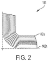
- a rotor segment 141 is shown.
- the rotor segment 141 is formed from a plurality of rotor laminates 142a-142n.
- each of the rotor laminates 142a-142n is an axially extending sheet. Therefore, in the illustrated embodiment, each rotor laminate 142a-142n has an axial length that corresponds to the axial length of the assembled rotor segment 141 or rotor 140. In the illustrated embodiment, each rotor laminate 142a-142n is disposed on the outer surface of the preceding rotor laminate 142a-142n, allowing the rotor segment 141 to be formed in a radially outward direction. In certain embodiments, the rotor segment 141 and the rotor laminates 142a-142n can be formed utilizing additive manufacturing methods.
- the rotor laminates 142a-142n can be formed from any suitable material, including, but not limited to rolled electrical steel.
- magnetic flux is aligned with the rolling direction of the electrical steel which corresponds to the axial direction of the rotor laminates 142a-142n. Therefore, in certain embodiments, magnetic flux is maximized in the axial direction of the rotor laminates 142a-142n, allowing for a rotor segment 141 or a rotor 140 formed from the axially extending rotor laminates 142a-142n to have a maximized magnetic flux density.
- the use of axially extending rotor laminates 142a-142n minimizes core losses and reduces variation of reluctance within the magnetic circuit as current is switched between phases. Further, the use of axially extending rotor laminates 142a-142n allows for greater power density, efficiency and dynamic performance for greater utilization of the magnetic circuit and decreased electromagnetic noise and vibration. Therefore, the use of axially extending rotor laminates 142a-142n allows for switched reluctance motors 100 to be created with a smaller volume envelope, lower inductance and lower costs, allowing for aviation and other suitable applications such as fuel pumps and ball-screw linear actuators.
- multiple rotor segments 141 can be assembled to form a rotor 140 as shown in FIG. 1 .
- the assembled rotor 140 is encapsulated in a resin epoxy.
- the resin epoxy of the assembled rotor 140 can be ground to meet tolerances including the air gap between the rotor 140 and the stator 130.
- stator segment 131 is shown.
- the stator segment 131 is formed from a plurality of stator laminates 132a-132n.
- each of the stator laminates 132a-132n is an axially extending sheet. Therefore, in the illustrated embodiment, each stator laminates 132a-132n has an axial length that corresponds to the axial length of the assembled stator segment 131 or stator 130. In the illustrated embodiment, each stator laminate 132a-132n is disposed on the outer surface of the preceding stator laminate 132a-132n, allowing the stator segment 131 to be formed in a radially outward direction. In certain embodiments, the stator segment 131 and the stator laminates 132a-132n can be formed utilizing additive manufacturing methods.
- the stator laminates 132a-132n can be formed from any suitable material, including, but not limited to rolled electrical steel or any other suitable ferromagnetic steel or alloy.
- suitable material including, but not limited to rolled electrical steel or any other suitable ferromagnetic steel or alloy.
- magnetic flux is aligned with the rolling direction of the electrical steel which corresponds to the axial direction of the stator laminates 132a-132n. Therefore, in certain embodiments, magnetic flux is maximized in the axial direction of the stator laminates 132a-132n, allowing for a stator segment 131 or a stator 130 formed from the axially extending stator laminates 132a-132n to have a maximized magnetic flux density.
- the use of axially extending stator laminates 132a-132n minimizes core losses and reduces variation of reluctance within the magnetic circuit as current is switched between phases. Further, the use of axially extending stator laminates 132a-132n allows for greater power density, efficiency and dynamic performance for greater utilization of the magnetic circuit and decreased electromagnetic noise and vibration. Therefore, the use of axially extending stator laminates 132a-132n allows for switched reluctance motors 100 to be created with a smaller volume envelope, lower inductance and lower costs, allowing for aviation and other suitable applications such as fuel pumps and ball-screw linear actuators.
- stator segments 131 can be assembled to form a stator 130 as shown in FIG. 1 .
- the coils 110a-110c can be disposed within the stator 130.
- the assembled stator 130 is encapsulated in a resin epoxy. Further, in certain embodiments, the resin epoxy of the assembled stator 130 can be ground to meet tolerances including the air gap between the rotor 140 and the stator 130.
Applications Claiming Priority (1)
| Application Number | Priority Date | Filing Date | Title |
|---|---|---|---|
| US15/252,495 US20180062457A1 (en) | 2016-08-31 | 2016-08-31 | Switched reluctance motor with axial laminated construction |
Publications (2)
| Publication Number | Publication Date |
|---|---|
| EP3291414A2 true EP3291414A2 (fr) | 2018-03-07 |
| EP3291414A3 EP3291414A3 (fr) | 2018-03-21 |
Family
ID=59738255
Family Applications (1)
| Application Number | Title | Priority Date | Filing Date |
|---|---|---|---|
| EP17188284.8A Withdrawn EP3291414A3 (fr) | 2016-08-31 | 2017-08-29 | Moteur à réluctance commutée, à structure stratifiée axiale |
Country Status (2)
| Country | Link |
|---|---|
| US (1) | US20180062457A1 (fr) |
| EP (1) | EP3291414A3 (fr) |
Families Citing this family (1)
| Publication number | Priority date | Publication date | Assignee | Title |
|---|---|---|---|---|
| US11228216B2 (en) | 2019-11-15 | 2022-01-18 | Ford Global Technologies, Llc | Stator for electric machine with conductors with varying cross-sectional shapes |
Family Cites Families (9)
| Publication number | Priority date | Publication date | Assignee | Title |
|---|---|---|---|---|
| FR1453957A (fr) * | 1965-07-30 | 1966-08-22 | Dispositif à induction électromagnétique à noyaux feuilletés | |
| US5095237A (en) * | 1990-03-20 | 1992-03-10 | Nova Corporation Of Alberta | Sectoral core for magnetic bearing |
| JPH09294359A (ja) * | 1996-04-25 | 1997-11-11 | Aisin Seiki Co Ltd | スイッチドリラクタンスモータ |
| JP3282521B2 (ja) * | 1996-07-08 | 2002-05-13 | トヨタ自動車株式会社 | リラクタンスモータ |
| US6960860B1 (en) * | 1998-06-18 | 2005-11-01 | Metglas, Inc. | Amorphous metal stator for a radial-flux electric motor |
| JP2000166131A (ja) * | 1998-12-02 | 2000-06-16 | Yoho Han | モ―タ或いは発電機用のステ―タ |
| KR100600758B1 (ko) * | 2004-09-15 | 2006-07-19 | 엘지전자 주식회사 | 모터의 스테이터 및 그 제조방법 |
| JP5288065B1 (ja) * | 2012-06-18 | 2013-09-11 | パナソニック株式会社 | モータ |
| US20150076951A1 (en) * | 2013-09-16 | 2015-03-19 | Hamilton Sundstrand Corporation | Electric machine construction |
-
2016
- 2016-08-31 US US15/252,495 patent/US20180062457A1/en not_active Abandoned
-
2017
- 2017-08-29 EP EP17188284.8A patent/EP3291414A3/fr not_active Withdrawn
Non-Patent Citations (1)
| Title |
|---|
| None |
Also Published As
| Publication number | Publication date |
|---|---|
| EP3291414A3 (fr) | 2018-03-21 |
| US20180062457A1 (en) | 2018-03-01 |
Similar Documents
| Publication | Publication Date | Title |
|---|---|---|
| US9099905B2 (en) | Radially embedded permanent magnet rotor and methods thereof | |
| US9246364B2 (en) | Radially embedded permanent magnet rotor and methods thereof | |
| US11043857B2 (en) | Motor having non-circular stator | |
| US9362792B2 (en) | Radially embedded permanent magnet rotor having magnet retention features and methods thereof | |
| US9882440B2 (en) | Radially embedded permanent magnet rotor and methods thereof | |
| US9831727B2 (en) | Permanent magnet rotor and methods thereof | |
| JP5877777B2 (ja) | 回転電機、磁極ピース製造方法 | |
| US11300131B2 (en) | Electric motor system and turbo compressor provided therewith | |
| US20140103772A1 (en) | Radially embedded permanent magnet rotor and methods thereof | |
| JP2008141853A (ja) | 二軸同心軸モータ | |
| EP3352347B1 (fr) | Machine sans balai à aimant permanent (pm) à rotor externe | |
| EP2413482A1 (fr) | Aéronef | |
| CN113853724A (zh) | 四极同步磁阻马达 | |
| EP3291414A2 (fr) | Moteur à réluctance commutée, à structure stratifiée axiale | |
| JP4303579B2 (ja) | 三次元ステーター構造の回転機 | |
| US10404121B2 (en) | Electromechanical actuator damping | |
| EP3499686A2 (fr) | Machine électrique à réluctance commutée comprenant des barrières de flux polaires | |
| US10263491B2 (en) | Electromechanical actuator damping | |
| US20130002053A1 (en) | Slotless motors with grooved core | |
| EP3084929B1 (fr) | Stator pour une machine électrique | |
| CN105075069A (zh) | 用于电机的转动部件 | |
| WO2021240870A1 (fr) | Équipement électromagnétique et aéronef dans lequel un équipement électromagnétique est utilisé | |
| Judge | Permanent magnet axial field air core (PAAC) motors for naval applications | |
| US9692282B2 (en) | Method of fabricating electrical machine |
Legal Events
| Date | Code | Title | Description |
|---|---|---|---|
| PUAI | Public reference made under article 153(3) epc to a published international application that has entered the european phase |
Free format text: ORIGINAL CODE: 0009012 |
|
| PUAL | Search report despatched |
Free format text: ORIGINAL CODE: 0009013 |
|
| AK | Designated contracting states |
Kind code of ref document: A2 Designated state(s): AL AT BE BG CH CY CZ DE DK EE ES FI FR GB GR HR HU IE IS IT LI LT LU LV MC MK MT NL NO PL PT RO RS SE SI SK SM TR |
|
| AX | Request for extension of the european patent |
Extension state: BA ME |
|
| AK | Designated contracting states |
Kind code of ref document: A3 Designated state(s): AL AT BE BG CH CY CZ DE DK EE ES FI FR GB GR HR HU IE IS IT LI LT LU LV MC MK MT NL NO PL PT RO RS SE SI SK SM TR |
|
| AX | Request for extension of the european patent |
Extension state: BA ME |
|
| RIC1 | Information provided on ipc code assigned before grant |
Ipc: H02K 1/14 20060101AFI20180210BHEP Ipc: H02K 1/24 20060101ALI20180210BHEP |
|
| STAA | Information on the status of an ep patent application or granted ep patent |
Free format text: STATUS: THE APPLICATION IS DEEMED TO BE WITHDRAWN |
|
| 18D | Application deemed to be withdrawn |
Effective date: 20180922 |