EP3291181A1 - Gerät zur erfassung von betriebsdaten eines werkzeugs und system - Google Patents
Gerät zur erfassung von betriebsdaten eines werkzeugs und system Download PDFInfo
- Publication number
- EP3291181A1 EP3291181A1 EP16187273.4A EP16187273A EP3291181A1 EP 3291181 A1 EP3291181 A1 EP 3291181A1 EP 16187273 A EP16187273 A EP 16187273A EP 3291181 A1 EP3291181 A1 EP 3291181A1
- Authority
- EP
- European Patent Office
- Prior art keywords
- tool
- operating data
- housing
- sensor
- operating
- Prior art date
- Legal status (The legal status is an assumption and is not a legal conclusion. Google has not performed a legal analysis and makes no representation as to the accuracy of the status listed.)
- Granted
Links
Images


Classifications
-
- G—PHYSICS
- G07—CHECKING-DEVICES
- G07C—TIME OR ATTENDANCE REGISTERS; REGISTERING OR INDICATING THE WORKING OF MACHINES; GENERATING RANDOM NUMBERS; VOTING OR LOTTERY APPARATUS; ARRANGEMENTS, SYSTEMS OR APPARATUS FOR CHECKING NOT PROVIDED FOR ELSEWHERE
- G07C3/00—Registering or indicating the condition or the working of machines or other apparatus, other than vehicles
-
- G—PHYSICS
- G08—SIGNALLING
- G08C—TRANSMISSION SYSTEMS FOR MEASURED VALUES, CONTROL OR SIMILAR SIGNALS
- G08C17/00—Arrangements for transmitting signals characterised by the use of a wireless electrical link
- G08C17/02—Arrangements for transmitting signals characterised by the use of a wireless electrical link using a radio link
-
- G—PHYSICS
- G07—CHECKING-DEVICES
- G07C—TIME OR ATTENDANCE REGISTERS; REGISTERING OR INDICATING THE WORKING OF MACHINES; GENERATING RANDOM NUMBERS; VOTING OR LOTTERY APPARATUS; ARRANGEMENTS, SYSTEMS OR APPARATUS FOR CHECKING NOT PROVIDED FOR ELSEWHERE
- G07C3/00—Registering or indicating the condition or the working of machines or other apparatus, other than vehicles
- G07C3/08—Registering or indicating the production of the machine either with or without registering working or idle time
-
- A—HUMAN NECESSITIES
- A01—AGRICULTURE; FORESTRY; ANIMAL HUSBANDRY; HUNTING; TRAPPING; FISHING
- A01D—HARVESTING; MOWING
- A01D34/00—Mowers; Mowing apparatus of harvesters
- A01D34/006—Control or measuring arrangements
-
- B—PERFORMING OPERATIONS; TRANSPORTING
- B23—MACHINE TOOLS; METAL-WORKING NOT OTHERWISE PROVIDED FOR
- B23Q—DETAILS, COMPONENTS, OR ACCESSORIES FOR MACHINE TOOLS, e.g. ARRANGEMENTS FOR COPYING OR CONTROLLING; MACHINE TOOLS IN GENERAL CHARACTERISED BY THE CONSTRUCTION OF PARTICULAR DETAILS OR COMPONENTS; COMBINATIONS OR ASSOCIATIONS OF METAL-WORKING MACHINES, NOT DIRECTED TO A PARTICULAR RESULT
- B23Q17/00—Arrangements for observing, indicating or measuring on machine tools
- B23Q17/09—Arrangements for observing, indicating or measuring on machine tools for indicating or measuring cutting pressure or for determining cutting-tool condition, e.g. cutting ability, load on tool
- B23Q17/0995—Tool life management
-
- B—PERFORMING OPERATIONS; TRANSPORTING
- B25—HAND TOOLS; PORTABLE POWER-DRIVEN TOOLS; MANIPULATORS
- B25F—COMBINATION OR MULTI-PURPOSE TOOLS NOT OTHERWISE PROVIDED FOR; DETAILS OR COMPONENTS OF PORTABLE POWER-DRIVEN TOOLS NOT PARTICULARLY RELATED TO THE OPERATIONS PERFORMED AND NOT OTHERWISE PROVIDED FOR
- B25F5/00—Details or components of portable power-driven tools not particularly related to the operations performed and not otherwise provided for
-
- G—PHYSICS
- G01—MEASURING; TESTING
- G01H—MEASUREMENT OF MECHANICAL VIBRATIONS OR ULTRASONIC, SONIC OR INFRASONIC WAVES
- G01H11/00—Measuring mechanical vibrations or ultrasonic, sonic or infrasonic waves by detecting changes in electric or magnetic properties
- G01H11/06—Measuring mechanical vibrations or ultrasonic, sonic or infrasonic waves by detecting changes in electric or magnetic properties by electric means
- G01H11/08—Measuring mechanical vibrations or ultrasonic, sonic or infrasonic waves by detecting changes in electric or magnetic properties by electric means using piezoelectric devices
-
- G—PHYSICS
- G01—MEASURING; TESTING
- G01H—MEASUREMENT OF MECHANICAL VIBRATIONS OR ULTRASONIC, SONIC OR INFRASONIC WAVES
- G01H15/00—Measuring mechanical or acoustic impedance
Definitions
- the invention relates to a device for detecting operating data of a tool and a system comprising such a device and a tool.
- the invention has for its object to provide a device for recording operating data of a tool and a system by means of which a reliable and cost-effective operation data acquisition is possible, in particular across different types of devices.
- the invention achieves this object by a device for recording operating data of a tool according to claim 1 and a system according to claim 9.
- the device is provided or designed for recording operating data of a tool.
- the tool is driven by means of an electric motor and / or by means of an internal combustion engine.
- the device is provided separately from the tool and can be coupled with the tool, for example mechanically.
- the device may, for example, be releasably mechanically coupled to the tool, for example by being screwed to the tool, glued to a suitable location of the tool, coupled by means of a latching connection to the device or inserted or inserted into a chamber provided therefor.
- the tool for acquiring operational data of a tool includes a sensor configured to operate wirelessly, i. without a galvanic connection with components of the tool to detect at least one physical measured variable, the measured variable being dependent on an operating state of the tool.
- the device further comprises an evaluation device coupled to the sensor, for example in the form of a microcontroller.
- the evaluation device is designed to evaluate the measured variable detected by the sensor in order to determine or derive the operating data therefrom.
- the device further comprises an operating data memory which is designed to store the operating data.
- the device further has a communication interface, for example in the form of a WLAN interface or a Bluetooth interface, which is designed to transmit operating data wirelessly to a terminal or to send.
- the communication interface can be designed to transmit the operating data wirelessly, regardless of whether a terminal is within reach or not.
- the terminal can, for example, carry out evaluations of the operating data based on the received operating data and display these, for example, visually presented to a user.
- the senor is designed such that it is capable of detecting the measured variable, regardless of whether the tool is driven by means of an electric motor or an internal combustion engine. According to the invention, consequently, measured quantities and thus also operating data, for example in the form of operating hours, for a plurality of drive technologies, such as internal combustion engine driven, wired, accumulator-based, can be detected with the same device, without a line connection with the tool is necessary.
- the evaluation device is designed to determine operating data in the form of an operating period of the tool during which the electric motor or the internal combustion engine is active.
- the sensor is used in conjunction with the evaluation device for operating hours detection of the tool.
- the operating data in addition to the operating hours can also be other tool-relevant data, such as drive temperatures, drive power, load data, tool user-related data, states of charge and / or voltage states of an energy storage, locations, etc.
- the senor is an inductive sensor, such as a coil.
- the evaluation device is then designed to evaluate signals generated by the inductive sensor in order to determine the operating data.
- the inductive sensor By means of the inductive sensor, it is for example possible to detect changing electromagnetic and / or magnetic fields, for example caused by stray fields of electric motors, ignition pulses of internal combustion engines, current changes, moving magnets in a flywheel of the tool, a generator, etc.
- the operating data particularly in the form of operating hours of the tool, can be detected reliably and independently of a drive type of the tool as the changing ones electromagnetic and / or magnetic fields only during operation of the tool arise.
- the evaluation device may, for example, evaluate a rate of change of the electromagnetic field and compare it with a reference value, wherein in the event that the rate of change of the electromagnetic field is greater than the reference value, the operating time or a service hour counter is increased accordingly.
- the senor may be an acoustic sensor, wherein the evaluation device is coupled to the acoustic sensor and is designed to evaluate signals generated by the acoustic sensor in order to determine the operating data.
- the device has an electrical energy store, for example in the form of a battery, in particular in the form of a button cell.
- the device has electrical, resilient contact elements, which are designed to electrically contact corresponding electrical contacts, in particular contact surfaces, of the electrical energy store.
- the device has a housing, for example made of plastic, which may have an open and a closed state. In the open state of the housing, the electrical energy store can be removed from the housing or inserted into the housing. The housing is formed so corresponding to the electrical energy storage that the electrical energy storage is held in the closed state of the housing by means of the housing and not by means of the electrical contact elements in position.
- the resilient contact elements are pressed in the closed state of the housing due to their spring tension against the corresponding contacts or contact surfaces in order to effect electrical contact with low contact resistance.
- the spring tension is used only for optimum electrical contact, but not for mechanical fixation of the electrical energy storage in the housing.
- the housing assumes the function of fixing the electrical energy storage due to its shape and the resilient contact elements take over the function of electrical contact.
- the contact elements can be led out of the housing to be electrically connected there to corresponding terminals, for example on a circuit board.
- the housing may have a plastic tub for receiving the energy storage device, through which the electrical contact elements are led to the outside.
- the housing may have a cover which can be placed on the plastic tub. The housing can realize a certain degree of protection.
- the operational data memory is a volatile memory, such as a Random Access Memory (RAM).
- the device may further include a non-volatile memory, such as a FLASH memory.
- the device can periodically record the operating data at a repetition frequency or sampling rate, for example 1 Hz, and store it in the operating data memory at the repetition frequency.
- the storage in the operation data memory can be made under the condition that the operation data has changed, i. with unchanged operating data, as they are typically with inactive tool, the storage in the operating data storage can be omitted.
- the device may be configured to store the operating data in the non-volatile memory as soon as the operating data has changed by more than a predetermined threshold.
- the recorded operating hours For operating data in the form of an operating period or operating hours of the tool, for example, the recorded operating hours, if they have changed by any value greater than zero, periodically with the repetition frequency or sampling rate in the operating data memory, for example, in a memory cell provided for this operating data memory, get saved. Only when the recorded operating hours have changed by more than the predetermined threshold value, for example 1 minute, are the operating hours recorded correspondingly updated stored in the non-volatile memory, for example in the event of a battery change not losing the last detected value or only to cause a small measurement error.
- This approach saves energy and significantly extends the life of an electrical energy store or battery that provides operating power to the device because storing in the volatile memory requires significantly less power than storing in the non-volatile memory.
- the communication interface may be configured to continuously transmit the operating data wirelessly to the terminal.
- a fixed or varying time interval may be used for transmission.
- the system according to the invention comprises a device described above and a tool which is driven by means of an electric motor or an internal combustion engine.
- the electric motor may be a universal motor, or a brushed DC motor, or a DC brushless motor, or a three-phase motor.
- the tool may be a chainsaw, or a hedge trimmer, or a leaf blower, or a leaf vacuum, or a lawn mower, or a brushcutter, or a similar tool, especially for landscaping.
- the tool may, for example, continue to be a cordless screwdriver or a food processor, etc.
- the system may include a terminal.
- the terminal may be any data processing device having a suitable wireless interface configured for wireless communication with the communication interface of the operational data acquisition device.
- the terminal may be a mobile terminal, such as a mobile phone or a tablet.
- the terminal can also be stationary.
- the terminal may form or be a gateway, which forwards the received operating data to a server, for example, to a so-called cloud storage forwards, which stores the operating data.
- the operating data stored in the cloud memory can then be viewed and evaluated by means of a suitable tool, for example by means of a web browser.
- the device can be inserted into a corresponding receptacle of a nameplate of the tool.
- motorized tools have consistent nameplates throughout their series, so attaching the factory data acquisition device to the tool nameplate provides a consistent, easy-to-retrofit solution without the need to redefine a mounting location for each tool type to have to. It can be done by means of soft components (damper), foam-like potting compound, etc., a mechanical decoupling between the device and tool.
- the device or its housing can alternatively be glued to the tool.
- Fig. 1 1 shows a schematic block diagram of a system 12 comprising a tool 2 and a device 1 for operating data acquisition of the tool 2.
- the tool 2 here by way of example a motor saw, conventionally has a saw chain 20 driven by means of an electric motor 3 or by means of an internal combustion engine 4.
- a saw chain 20 driven by means of an electric motor 3 or by means of an internal combustion engine 4.
- the device 1 for operating data acquisition of the tool 2 is mechanically coupled or coupled to the tool 2, for example, inserted into a nameplate of the tool 2.
- the device 1 has a sensor unit 5, which is designed to wirelessly record operating data in the form of operating hours of the tool 2.
- the device 1 further has a volatile operating data memory 6, in which the recorded operating hours are stored continuously.
- the device 1 further comprises a non-volatile memory 17 in which the detected operating hours are stored as soon as they have changed by more than a predetermined threshold.
- the non-volatile memory 17 thus serves as an operating hours counter, which does not lose its stored operating hour value even with a battery change.
- the device 1 further has a communication interface 7 in the form of a Bluetooth interface, which is configured to continuously and unsolicitedly send the recorded operating hours to a terminal 8 in the form of a tablet or a mobile telephone.
- the sensor unit 5 has an inductive sensor 9 in the form of a coil. Furthermore, the sensor unit 5 has an evaluation device 11 coupled to the inductive sensor 9, for example in the form of a microcontroller with integrated analog components, which is designed to evaluate signals generated by the inductive sensor 9 in order to detect the operating hours, ie to detect whether the electric motor 3 and the engine 4 is active or not.
- an acoustic sensor 10 may be used.
- a changing magnetic field is generated, for example due to moving permanent magnets, a movement of a flywheel, and / or a movement of electric charges (current, spark, etc.).
- the changing magnetic field induces a voltage in the inductive sensor 9, which voltage can be detected and evaluated by means of the evaluation device 11.
- inductive coupling is typically also a capacitive coupling, since the winding surface of the inductive sensor 9 acts capacitively, so that in addition to the energy transfer due to magnetic coupling and an energy transfer due to capacitive coupling is given.
- An evaluation of the signals generated by means of the inductive sensor 9 can be carried out after a suitable high-impedance signal conditioning, filtering by means of a high-pass filter, etc. Further processing of the signals conditioned in this way can take place by means of a peak-hold element and / or via rapid reaction by means of hardware and / or software.
- the energy transfer to the inductive sensor 9 is typically caused by a variable magnetic field due to spark and / or flywheel.
- the energy transfer to the inductive sensor 9 is typically carried out by alternating current and commutation of the series-wound motors.
- the energy transfer to the inductive sensor 9 is typically carried out by pulsating DC voltage (PWM), alternating currents at the motor, moving permanent magnets and / or commutation.
- PWM pulsating DC voltage
- the inductive sensor 9 may be formed as a wired coil, as an inductance on a chip or as an SMD coil.
- a frequency bandwidth of the arrangement of inductive sensor 9 and evaluation device 11 is typically chosen such that slow changes in the magnetic field that are not specific to the operating state of the tool 2 are suppressed.
- the frequency bandwidth can be further selected such that high interference frequencies are also suppressed.
- the inductive sensor 9 may have a plurality of individual partial coils, which are aligned differently with each other. Furthermore, a defined positioning of the inductive sensor 9 on the tool 2 or a defined orientation of the inductive sensor 9 with respect to the tool 2 can be selected.
- the evaluation of the signals generated by means of the inductive sensor 9 can be carried out according to the sample-and-hold principle, wherein suitable electrical components realize a peak or peak detector that stores a sampled signal value as long as it is for the intended time grid for Scanning is required.
- a microcontroller of the evaluation device 11 can, for example, be woken up cyclically and evaluate a stored signal value, for example in the form of a voltage. If the stored voltage value is greater than a defined threshold, for example, an active tool can be closed and the operating hours counter can be incremented accordingly. After evaluation, the stored signal value can be reset.
- the device 1 has an electrical energy store 13 in the form of a button cell.
- Two resilient electrical contact elements 14, 15 of the device 1 are provided to electrically contact corresponding electrical contact surfaces of the electrical energy accumulator 13.
- the device 1 further comprises a housing 16 made of plastic, wherein the housing 16 has a trough 16a and a lid 16b.
- the lid 16b In an open state of the housing 16, the lid 16b is removed from the tub 16a. In a closed state of the housing 16, the lid 16b closes the tub 16a fluid-tight.
- the electrical energy store 13 can be inserted into or removed from the trough 16a, so that the electrical energy store 13 can be replaced if necessary.
- the housing 16 is shaped such that the electrical energy storage 13 held in the closed state of the housing 16 by the shape of the housing 16 in position or is fixed.
- the two resilient electrical contact elements 14, 15 do not contribute to the mechanical fixation, but serve for safe electrical contact.
- an optional resilient elastomeric ring 16 c may be provided as part of the housing 16, which is arranged in the closed state of the housing 16 between the cover 16 b and the energy storage 13 and allows elastic fixing of the energy storage device 13 in the housing 16.
- Fig. 4 a typical installation situation of the device 1 is shown in the tool 2.
- Fig. 4 shows a nameplate 19 of the tool 2.
- the device 1 is connected to its housing 16 (see Fig. 3 ) used in a corresponding receptacle 18 of the nameplate 19, for example clipped. Since such nameplates 19 are typically used identically for several tools, a universal integration of the device 1 into different types of tools can be achieved in this way.
- the in Fig. 3 shown housing 16 may be provided as a tool-independent universal housing.
- a device-specific adapter element may be provided which has a device-specific mechanical interface for mechanical coupling to the device and an always the same mechanical interface for mechanical coupling with the universal housing. In this way, a high DC component can be achieved.
- the communication interface 7 can send the operating data in the so-called iBeacon format.
- iBeacon format For this specific data format, reference is also made to the relevant specialist literature.
- Some terminal operating systems offer the option to search for a specific number of so-called beacon IDs in the background of the operating system without the need for an application that searches through consecutive queries for beacon IDs from devices that are in Radio range of the terminals are located.
- the iBeacon format because of its specification, is not capable of transporting all information necessary in the context of operational data transmission.
- radio telegrams in iBeacon format not the operating data are included or encoded, but an ID, which causes in the terminals that an app stealige application (APP) can be started and certain functions can be performed.
- APP app stealige application
- Radio telegrams in a proprietary format can then be sent between the radio telegrams in the iBeacon format, whereby the proprietary format is suitable for transporting all information necessary in the context of the operational data transmission, which can then be evaluated by means of the previously started APP.
Landscapes
- Physics & Mathematics (AREA)
- General Physics & Mathematics (AREA)
- Engineering & Computer Science (AREA)
- Mechanical Engineering (AREA)
- Acoustics & Sound (AREA)
- Life Sciences & Earth Sciences (AREA)
- Environmental Sciences (AREA)
- Computer Networks & Wireless Communication (AREA)
- Portable Nailing Machines And Staplers (AREA)
- Arrangements For Transmission Of Measured Signals (AREA)
Abstract
Description
- Die Erfindung betrifft ein Gerät zur Erfassung von Betriebsdaten eines Werkzeugs und ein System mit einem solchen Gerät und einem Werkzeug.
- Der Erfindung liegt die Aufgabe zugrunde, ein Gerät zur Erfassung von Betriebsdaten eines Werkzeugs und ein System zur Verfügung zu stellen, mittels derer eine zuverlässige und kostengünstige Betriebsdatenerfassung möglich ist, insbesondere über verschiedene Gerätetypen hinweg.
- Die Erfindung löst diese Aufgabe durch ein Gerät zur Erfassung von Betriebsdaten eines Werkzeugs nach Anspruch 1 und ein System nach Anspruch 9.
- Das Gerät ist zur Erfassung von Betriebsdaten eines Werkzeugs vorgesehen bzw. ausgebildet.
- Das Werkzeug ist mittels eines Elektromotors und/oder mittels eines Verbrennungsmotors angetrieben. Das Gerät ist getrennt von dem Werkzeug vorgesehen und mit dem Werkzeug, beispielsweise mechanisch, koppelbar. Das Gerät kann beispielsweise lösbar mit dem Werkzeug mechanisch gekoppelt sein, beispielsweise indem es mit dem Werkzeug verschraubt, auf eine geeignete Stelle des Werkzeugs geklebt, mittels einer rastenden Verbindung mit dem Gerät gekoppelt oder in eine hierfür vorgesehene Kammer eingesetzt bzw. eingelegt wird.
- Das Gerät zur Erfassung von Betriebsdaten eines Werkzeugs weist einen Sensor auf, der dazu ausgebildet ist, drahtlos, d.h. ohne eine galvanische Verbindung mit Komponenten des Werkzeugs, mindestens eine physikalische Messgröße zu erfassen, wobei die Messgröße von einem Betriebszustand des Werkzeugs abhängig ist.
- Das Gerät weist weiter eine mit dem Sensor gekoppelte Auswerteeinrichtung auf, beispielsweise in Form eines Microcontrollers. Die Auswerteeinrichtung ist dazu ausgebildet, die mittels des Sensors erfasste Messgröße auszuwerten, um daraus die Betriebsdaten zu ermitteln bzw. abzuleiten.
- Das Gerät weist weiter einen Betriebsdatenspeicher auf, der dazu ausgebildet ist, die Betriebsdaten zu speichern.
- Das Gerät weist weiter eine Kommunikationsschnittstelle auf, beispielsweise in Form einer WLAN-Schnittstelle oder einer Bluetooth-Schnittstelle, die dazu ausgebildet ist, Betriebsdaten drahtlos zu einem Endgerät zu übertragen bzw. zu senden. Die Kommunikationsschnittstelle kann dazu ausgebildet sein, die Betriebsdaten drahtlos zu senden, unabhängig davon, ob sich ein Endgerät in Reichweite befindet oder nicht.
- Das Endgerät kann beispielsweise basierend auf den empfangenen Betriebsdaten Auswertungen der Betriebsdaten vornehmen und diese beispielsweise einem Benutzer optisch aufbereitet darstellen.
- In einer Ausführungsform ist der Sensor derart ausgebildet, dass er dazu in der Lage ist, unabhängig davon, ob das Werkzeug mittels eines Elektromotors oder eines Verbrennungsmotors angetrieben ist, die Messgröße zu erfassen. Erfindungsgemäß können folglich Messgrößen und damit auch Betriebsdaten, beispielsweise in Form von Betriebsstunden, für eine Vielzahl von Antriebstechnologien, wie beispielsweise verbrennungsmotorgetrieben, kabelgebunden, Akkumulator-basiert, mit demselben Gerät erfasst werden, ohne dass eine leitungsgebundene Verbindung mit dem Werkzeug notwendig ist.
- In einer Ausführungsform ist die Auswerteeinrichtung dazu ausgebildet, Betriebsdaten in Form einer Betriebsdauer des Werkzeugs zu ermitteln, während der der Elektromotor oder der Verbrennungsmotor aktiv ist. Mit anderen Worten dient der Sensor in Verbindung mit der Auswerteeinrichtung zur Betriebsstundenerfassung des Werkzeugs. Es versteht sich, dass es sich bei den Betriebsdaten neben den Betriebsstunden auch um weitere werkzeugbetriebsrelevante Daten handeln kann, beispielsweise um Antriebstemperaturen, Antriebsleistungen, Lastdaten, werkzeugbenutzerbezogene Daten, Ladezustände und/oder Spannungszustände eines Energiespeichers, Einsatzorte, usw.
- In einer Ausführungsform ist der Sensor ein induktiver Sensor, beispielsweise eine Spule. Die Auswerteeinrichtung ist dann dazu ausgebildet, mittels des induktiven Sensors erzeugte Signale auszuwerten, um die Betriebsdaten zu ermitteln.
- Mittels des induktiven Sensors ist es beispielsweise möglich, sich ändernde elektromagnetische und/oder magnetische Felder zu detektieren, beispielsweise verursacht durch Streufelder von Elektromotoren, Zündimpulse von Verbrennungsmotoren, Stromänderungen, sich bewegende Magnete in einem Schwungrad des Werkzeugs, eines Generators, etc. Auf diese Weise können die Betriebsdaten, insbesondere in Form von Betriebsstunden des Werkzeugs, zuverlässig und unabhängig von einem Antriebstyp des Werkzeugs erfasst werden, da die sich ändernden elektromagnetischen und/oder magnetischen Felder nur während des Betriebs des Werkzeugs entstehen. Die Auswerteeinrichtung kann beispielsweise eine Änderungsrate des elektromagnetischen Feldes auswerten und mit einem Referenzwert vergleichen, wobei für den Fall, dass die Änderungsrate des elektromagnetischen Feldes größer als der Referenzwert ist, die Betriebsdauer bzw. ein Betriebsstundezähler entsprechend erhöht wird.
- Alternativ oder zusätzlich kann der Sensor ein akustischer Sensor sein, wobei die Auswerteeinrichtung mit dem akustischen Sensor gekoppelte ist und dazu ausgebildet ist, mittels des akustischen Sensors erzeugte Signale auszuwerten, um die Betriebsdaten zu ermitteln.
- In einer Ausführungsform weist das Gerät einen elektrischen Energiespeicher auf, beispielsweise in Form einer Batterie, insbesondere in Form einer Knopfzelle. Weiter weist das Gerät elektrische, federnde Kontaktelemente auf, die dazu ausgebildet sind, korrespondierende elektrische Kontakte, insbesondere Kontaktflächen, des elektrischen Energiespeichers elektrisch zu kontaktieren. Weiter weist das Gerät ein Gehäuse auf, beispielsweise aus Kunststoff, das einen offenen und einen geschlossenen Zustand aufweisen kann. Im offenen Zustand des Gehäuses ist der elektrische Energiespeicher aus dem Gehäuse entnehmbar oder in das Gehäuse einsetzbar. Das Gehäuse ist derart korrespondierend zum elektrischen Energiespeicher geformt, dass der elektrische Energiespeicher im geschlossenen Zustand des Gehäuses mittels des Gehäuses und nicht mittels der elektrischen Kontaktelemente in Position gehalten ist. Die federnden Kontaktelemente werden im geschlossenen Zustand des Gehäuses aufgrund ihrer Federspannung gegen die korrespondierenden Kontakte bzw. Kontaktflächen gedrückt, um eine elektrische Kontaktierung mit geringem Übergangswiderstand zu bewirken. Die Federspannung dient hierbei jedoch lediglich zur optimalen elektrischen Kontaktierung, nicht jedoch zur mechanischen Fixierung des elektrischen Energiespeichers im Gehäuse. Mit anderen Worten übernimmt das Gehäuse aufgrund seiner Formgebung die Funktion der Fixierung des elektrischen Energiespeichers und die federnden Kontaktelemente übernehmen die Funktion der elektrischen Kontaktierung. Die Kontaktelemente können aus dem Gehäuse herausgeführt sein, um dort elektrisch mit korrespondierenden Anschlüssen, beispielsweise auf einer Platine, verbunden zu werden.
- Das Gehäuse kann eine Kunststoffwanne zur Aufnahme des Energiespeichers aufweisen, durch die die elektrischen Kontaktelemente nach außen geführt sind. Das Gehäuse kann einen auf die Kunststoffwanne aufsetzbaren Deckel aufweisen. Das Gehäuse kann eine bestimmte Schutzklasse realisieren.
- In einer Ausführungsform ist der Betriebsdatenspeicher ein flüchtiger Speicher, beispielsweise ein RAM (Random Access Memory). Das Gerät kann weiter einen nicht-flüchtigen Speicher aufweisen, beispielsweise einen FLASH-Speicher. Das Gerät kann die Betriebsdaten periodisch mit einer Wiederholfrequenz bzw. Abtastrate, beispielsweise 1 Hz, erfassen und in dem Betriebsdatenspeicher mit der Wiederholfrequenz speichern. Das Speichern in dem Betriebsdatenspeicher kann unter der Bedingung erfolgen, dass sich die Betriebsdaten geändert haben, d.h. bei unveränderten Betriebsdaten, wie diese typisch bei nicht aktivem Werkzeug sind, kann das Speichern in dem Betriebsdatenspeicher entfallen. Das Gerät kann dazu ausgebildet sein, die Betriebsdaten in dem nicht-flüchtigen Speicher zu speichern, sobald sich die Betriebsdaten um mehr als einen vorgegebenen Schwellenwert verändert haben.
- Für Betriebsdaten in Form einer Betriebsdauer bzw. Betriebsstunden des Werkzeugs können beispielsweise die erfassten Betriebsstunden, sofern sie sich um einen beliebigen Wert größer als Null geändert haben, periodisch mit der Wiederholfrequenz bzw. Abtastrate in dem Betriebsdatenspeicher, beispielsweise in einer hierfür vorgesehenen Speicherzelle des Betriebsdatenspeichers, gespeichert werden. Erst wenn sich die erfassten Betriebsstunden um mehr als den vorgegebenen Schwellenwert, beispielsweise 1 Minute, geändert haben, werden die erfassten Betriebsstunden entsprechend aktualisiert in dem nicht-flüchtigen Speicher gespeichert, um beispielsweise im Falle eines Batteriewechsels den letzten erfassten Wert nicht zu verlieren bzw. nur einen geringen Messfehler zu verursachen. Dieses Vorgehen spart Energie und verlängert die Laufzeit eines elektrischen Energiespeichers bzw. einer Batterie, der bzw. die das Gerät mit Betriebsenergie versorgt, erheblich, da das Speichern in dem flüchtigen Speicher deutlich weniger Energie erfordert als das Speichern in dem nicht-flüchtigen Speicher.
- In einer Ausführungsform kann die Kommunikationsschnittstelle dazu ausgebildet sein, die Betriebsdaten fortlaufend drahtlos zu dem Endgerät zu übertragen. Beispielsweise kann die Kommunikationsschnittstelle dazu ausgebildet sein, nach einer bestimmten Anzahl n (n = 1, 2, ...) von Erfassungen bzw. Abtastungen der Betriebsdaten die Betriebsdaten unaufgefordert drahtlos zu dem Endgerät zu übertragen, um beispielsweise die Ortbarkeit des Geräts mittels einem Endgerät zu ermöglichen. Es kann ein festes oder ein veränderliches Zeitintervall zum Übertragen bzw. Senden verwendet werden.
- Das erfindungsgemäße System weist ein oben beschriebenes Gerät und ein Werkzeug auf, das mittels eines Elektromotors oder eines Verbrennungsmotors angetrieben ist.
- Der Elektromotor kann ein Universalmotor, oder ein bürstenbehafteter Gleichstrommotor, oder ein bürstenloser Gleichstrommotor, oder ein Drehstrommotor sein.
- Das Werkzeug kann eine Motorsäge, oder eine Heckenschere, oder ein Laubbläser, oder ein Laubsauger, oder ein Rasenmäher, oder ein Freischneider, oder ein vergleichbares Werkzeug, insbesondere zur Landschaftspflege, sein. Das Werkzeug kann beispielsweise weiter ein Akkuschrauber oder eine Küchenmaschine, etc. sein.
- Das System kann ein Endgerät aufweisen. Das Endgerät kann eine beliebige datenverarbeitende Einrichtung sein, die eine geeignete drahtlose Schnittstelle aufweist, die zur drahtlosen Kommunikation mit der Kommunikationsschnittstelle des Geräts zur Erfassung von Betriebsdaten ausgebildet ist.
- Das Endgerät kann ein mobiles Endgerät sein, wie beispielsweise ein Mobiltelefon oder ein Tablet. Das Endgerät kann auch stationär sein. Beispielsweise kann das Endgerät ein Gateway bilden bzw. sein, das die empfangenen Betriebsdaten an einen Server weiterleitet, beispielsweise an einen sogenannten Cloud-Speicher weiterleitet, der die Betriebsdaten speichert. Die im Cloud-Speicher gespeicherten Betriebsdaten können dann mittels eines geeigneten Werkzeugs, beispielsweise mittels eines Web-Browsers, betrachtet und ausgewertet werden.
- Das Gerät kann in eine korrespondierende Aufnahme eines Typenschilds des Werkzeugs eingesetzt sein. Häufig weisen motorisch betriebene Werkzeuge über ganze Baureihen hinweg einheitliche Typenschilder auf, so dass mittels Anbringen des Geräts zur Betriebsdatenerfassung im Typenschild des Werkzeugs eine einheitliche, leicht nachrüstbare Lösung zur Verfügung gestellt werden kann, ohne dass die Notwendigkeit besteht, einen Anbringungsort für jeden Werkzeugtyp neu definieren zu müssen. Es kann mittels Weichkomponenten (Dämpfer), schaumartiger Vergussmasse, etc. eine mechanische Entkopplung zwischen Gerät und Werkzeug erfolgen. Das Gerät bzw. sein Gehäuse kann alternativ auf das Werkzeug geklebt werden.
- Die Erfindung wird nachfolgend unter Bezugnahme auf die Zeichnungen detailliert beschrieben. Hierbei zeigen:
- Fig. 1
- ein schematisches Blockschaltbild eines Systems mit einem Werkzeug und einem Gerät zur Betriebsdatenerfassung des Werkzeugs,
- Fig. 2
- ein schematisches Blockschaltbild eines Betriebsdatensensors des in
Fig. 1 gezeigten Geräts zur Betriebsdatenerfassung, - Fig. 3
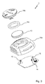
- eine perspektivische Explosionsdarstellung des in
Fig. 1 gezeigten Geräts zur Betriebsdatenerfassung und - Fig. 4
- eine perspektivische Darstellung eines Werkzeugs mit Typenschild und darin aufgenommenem Gerät zur Betriebsdatenerfassung.
-
Fig. 1 zeigt ein schematisches Blockschaltbild eines Systems 12 aufweisend ein Werkzeug 2 und ein Gerät 1 zur Betriebsdatenerfassung des Werkzeugs 2. - Das Werkzeug 2, hier exemplarisch eine Motorsäge, weist herkömmlich eine mittels eines Elektromotors 3 oder mittels eines Verbrennungsmotors 4 angetriebene Sägekette 20 auf. Insoweit sei auch auf die einschlägige Fachliteratur verwiesen.
- Das Gerät 1 zur Betriebsdatenerfassung des Werkzeugs 2 ist mit dem Werkzeug 2 mechanisch koppelbar bzw. gekoppelt, beispielsweise in ein Typenschild des Werkzeugs 2 eingesetzt.
- Das Gerät 1 weist eine Sensoreinheit 5 auf, die dazu ausgebildet ist, drahtlos Betriebsdaten in Form von Betriebsstunden des Werkzeugs 2 zu erfassen.
- Das Gerät 1 weist weiter einen flüchtigen Betriebsdatenspeicher 6 auf, in dem die erfassten Betriebsstunden fortlaufend gespeichert werden.
- Das Gerät 1 weist weiter einen nicht-flüchtigen Speicher 17 auf, in dem die erfassten Betriebsstunden dann gespeichert werden, sobald sie sich um mehr als einen vorgegebenen Schwellenwert verändert haben. Der nicht-flüchtige Speicher 17 dient folglich als Betriebsstundenzähler, der seinen gespeicherten Betriebsstundenwert auch bei einem Batteriewechsel nicht verliert.
- Das Gerät 1 weist weiter eine Kommunikationsschnittstelle 7 in Form einer BluetoothSchnittstelle auf, die dazu ausgebildet ist, die erfassten Betriebsstunden fortlaufend und unaufgefordert zu einem Endgerät 8 in Form eines Tablets oder eines Mobiltelefons zu senden.
- Bezugnehmend auf
Fig. 2 weist die Sensoreinheit 5 einen induktiven Sensor 9 in Form einer Spule auf. Weiter weist die Sensoreinheit 5 eine mit dem induktiven Sensor 9 gekoppelte Auswerteeinrichtung 11 auf, beispielsweise in Form eines Microcontrollers mit integrierten analogen Komponenten, die bzw. der dazu ausgebildet ist, mittels des induktiven Sensors 9 erzeugte Signale auszuwerten, um die Betriebsstunden zu erfassen, d.h. zu erfassen, ob der Elektromotor 3 bzw. der Verbrennungsmotor 4 aktiv ist oder nicht. - Anstelle des oder zusätzlich zum induktiven Sensor 9 kann ein akustischer Sensor 10 verwendet werden.
- Bei aktivem Elektromotor 3 bzw. Verbrennungsmotor 4 wird ein sich änderndes magnetisches Feld erzeugt, beispielsweise aufgrund von bewegten Dauermagneten, einer Bewegung eines Schwungrads, und/oder einer Bewegung elektrischer Ladungen (Strom, Zündfunke, etc.).
- Das sich ändernde magnetische Feld induziert im induktiven Sensor 9 eine Spannung, die mittels der Auswerteeinrichtung 11 erfasst und ausgewertet werden kann.
- Zusätzlich zu der beschriebenen induktiven Kopplung erfolgt typisch auch eine kapazitive Kopplung, da die Wicklungsfläche des induktiven Sensors 9 kapazitiv wirkt, so dass zusätzlich zur Energieübertragung aufgrund magnetischer Kopplung auch eine Energieübertragung aufgrund kapazitiver Kopplung gegeben ist.
- Eine Auswertung der mittels des induktiven Sensors 9 erzeugten Signale kann nach einer geeigneten hochohmigen Signalkonditionierung, Filterung mittels eines Hochpasses usw. erfolgen. Eine Weiterverarbeitung der derart konditionierten Signale kann mittels eines Peak-HoldGlieds und/oder über schnelle Reaktion per Hard- und/oder Software erfolgen.
- Bei Werkzeugen mit Verbrennungsmotoren wird die Energieübertragung zum induktiven Sensor 9 typisch durch ein veränderliches Magnetfeld aufgrund von Zündfunken und/oder Schwungrad bewirkt.
- Bei Werkzeugen mit netzgespeisten Elektroantrieben erfolgt die Energieübertragung zum induktiven Sensor 9 typisch durch Wechselstrom und Kommutierung der Reihenschlussmotoren.
- Bei Werkzeugen mit akkugespeisten Elektroantrieben erfolgt die Energieübertragung zum induktiven Sensor 9 typisch durch pulsierende Gleichspannung (PWM), Wechselströme am Motor, bewegte Permanentmagnete und/oder Kommutierung.
- Der induktive Sensor 9 kann als bedrahtete Spule, als eine Induktivität auf einem Chip oder als eine SMD-Spule ausgebildet sein.
- Eine Frequenzbandbreite der Anordnung aus induktivem Sensor 9 und Auswerteeinrichtung 11 ist typisch derart gewählt, dass langsame Änderungen des Magnetfelds, die nicht spezifisch für den Betriebszustand des Werkzeugs 2 sind, unterdrückt werden. Die Frequenzbandbreite kann weiter derart gewählt werden, dass hohe Störfrequenzen ebenfalls unterdrückt werden.
- Für die Erfassung der mittels des Werkzeugs 2 erzeugten Felder ist eine Flussrichtung der Felder in Bezug auf den induktiven Sensor 9 zu berücksichtigen. Der induktive Sensor 9 kann mehrere einzelne Teilspulen aufweisen, die zueinander unterschiedlich ausgerichtet sind. Weiter kann eine definierte Positionierung des induktiven Sensors 9 an dem Werkzeug 2 bzw. eine definierte Ausrichtung des induktiven Sensors 9 in Bezug auf das Werkzeug 2 gewählt werden.
- Die Auswertung der mittels des induktiven Sensors 9 erzeugten Signale kann nach dem Sample-and-hold-Prinzip erfolgen, wobei geeignete elektrische Bauelemente einen Spitzenwert- oder Peak-Detektor realisieren, der einen abgetasteten Signalwert so lange speichert, wie es für das vorgesehene Zeitraster zum Abtasten erforderlich ist.
- Ein Microcontroller der Auswerteeinrichtung 11 kann beispielsweise zyklisch aufgeweckt werden und einen gespeicherten Signalwert, beispielsweise in Form einer Spannung, auswerten. Wenn der gespeicherte Spannungswert größer als ein definierter Schwellenwert ist, kann beispielsweise auf ein aktives Werkzeug geschlossen werden und der Betriebsstundenzähler kann entsprechend inkrementiert werden. Nach dem Auswerten kann der gespeicherte Signalwert zurückgesetzt werden.
- Bezugnehmend auf
Fig. 3 weist das Gerät 1 einen elektrischen Energiespeicher 13 in Form einer Knopfzelle auf. Zwei federnde elektrische Kontaktelemente 14, 15 des Geräts 1 sind dazu vorgesehen, korrespondierende elektrische Kontakteflächen des elektrischen Energiespeichers 13 elektrisch zu kontaktieren. - Das Gerät 1 weist weiter ein Gehäuse 16 aus Kunststoff auf, wobei das Gehäuse 16 eine Wanne 16a und einen Deckel 16b aufweist. In einem offenen Zustand des Gehäuses 16 ist der Deckel 16b von der Wanne 16a entfernt. In einem geschlossenen Zustand des Gehäuses 16 verschließt der Deckel 16b die Wanne 16a fluiddicht.
- Im offenen Zustand des Gehäuses 16 ist der elektrische Energiespeicher 13 in die Wanne 16a einsetzbar bzw. aus dieser entnehmbar, so dass der elektrische Energiespeicher 13 bei Bedarf ersetzt werden kann.
- Das Gehäuse 16 ist derart geformt, dass der elektrische Energiespeicher 13 im geschlossenen Zustand des Gehäuses 16 durch die Formgebung des Gehäuses 16 in Position gehalten bzw. fixiert ist. Die beiden federnden elektrischen Kontaktelemente 14, 15 tragen zur mechanischen Fixierung nicht bei, sondern dienen zur sicheren elektrischen Kontaktierung.
- Weiter kann ein optionaler federelastischer Elastomer-Ring 16c als Teil des Gehäuses 16 vorgesehen sein, der im geschlossenen Zustand des Gehäuses 16 zwischen dem Deckel 16b und dem Energiespeicher 13 angeordnet ist und der eine elastische Fixierung des Energiespeichers 13 im Gehäuse 16 ermöglicht.
- In
Fig. 4 ist eine typische Einbausituation des Geräts 1 in das Werkzeug 2 dargestellt.Fig. 4 zeigt ein Typenschild 19 des Werkzeugs 2. Das Gerät 1 ist mit seinem Gehäuse 16 (sieheFig. 3 ) in eine korrespondierende Aufnahme 18 des Typenschilds 19 eingesetzt, beispielsweise geclipst. Da derartige Typenschilder 19 üblicherweise identisch für mehrere Werkzeuge verwendet werden, kann auf diese Weise eine universelle Integration des Geräts 1 in unterschiedliche Werkzeugtypen erzielt werden. - Alternativ oder zusätzlich zur Integration des Geräts in ein Werkzeug-Typenschild kann das in
Fig. 3 gezeigte Gehäuse 16 als werkzeugunspezifisches Universalgehäuse vorgesehen sein. Zur Anpassung an ein spezifisches Werkzeug kann dann ein gerätespezifisches Adapterelement vorgesehen sein, das eine gerätespezifische mechanische Schnittstelle zur mechanischen Kopplung mit dem Gerät und eine immer gleiche mechanische Schnittstelle zur mechanischen Kopplung mit dem Universalgehäuse aufweist. Auf diese Weise lässt sich ein hoher Gleichanteil an Baugruppen erzielen. - Die Kommunikationsschnittstelle 7 kann die Betriebsdaten im so genannten iBeacon-Format senden. Zu diesem spezifischen Datenformat sei auch auf die einschlägige Fachliteratur verwiesen.
- Manche Betriebssysteme von Endgeräten bieten die Möglichkeit, im Hintergrund des Betriebssystems sehr energiesparend nach einer bestimmten Anzahl so genannter Beacon-IDs zu suchen, ohne dass hierzu eine Anwendung aktiv sein muss, die durch fortlaufende Abfragen nach Beacon-IDs von Geräten sucht, die sich in Funkreichweite der Endgeräte befinden.
- Das iBeacon-Format ist jedoch aufgrund seiner Spezifikation nicht geeignet, alle im Kontext der Betriebsdatenübertragung notwendigen Informationen zu transportieren.
- Um dennoch die im Betriebssystem vorgesehenen energiesparenden Funktionen nutzen zu können, die das iBeacon-Format voraussetzen, kann wie folgt verfahren werden.
- Im Zuge der Betriebsdatenübertragung wird regelmäßig ein einzelnes Funktelegramm einer Anzahl m (m = 1, 2, ....) von Funktelegrammen im iBeacon Format gesendet, um eine Detektion des Geräts mittels des Betriebssystems der Endgeräte zu ermöglichen.
- In den Funktelegrammen im iBeacon Format sind dann zwar nicht die Betriebsdaten enthalten bzw. kodiert, dafür aber eine ID, die in den Endgeräten bewirkt, dass eine zughörige Applikation (APP) gestartet und gewisse Funktionen durchgeführt werden können.
- Zeitlich zwischen den Funktelegrammen im iBeacon Format können dann Funktelegramme in einem proprietären Format gesendet werden, wobei das proprietäre Format dazu geeignet ist, alle im Kontext der Betriebsdatenübertragung notwendigen Informationen zu transportieren, die dann mittels der zuvor gestarteten APP ausgewertet werden können.
Claims (14)
- Gerät (1) zur Erfassung von Betriebsdaten eines Werkzeugs (2), wobei das Werkzeug (2) mittels eines Elektromotors (3) oder eines Verbrennungsmotors (4) angetrieben ist, wobei das Gerät (1) getrennt von dem Werkzeug (2) ausgebildet ist und mit dem Werkzeug (2) koppelbar ist, wobei das Gerät (1) aufweist:- einen Sensor (9), der dazu ausgebildet ist, drahtlos mindestens eine Messgröße zu erfassen, wobei die Messgröße von einem Betriebszustand des Werkzeugs abhängig ist,- eine mit dem Sensor (9) gekoppelte Auswerteeinrichtung (11), die dazu ausgebildet ist, die mittels des Sensors erfasste Messgröße auszuwerten, um daraus die Betriebsdaten zu ermitteln,- einen Betriebsdatenspeicher (6), der dazu ausgebildet ist, die Betriebsdaten zu speichern, und- eine Kommunikationsschnittstelle (7), die dazu ausgebildet ist, im Betriebsdatenspeicher (6) gespeicherte Betriebsdaten drahtlos zu einem Endgerät (8) zu übertragen.
- Gerät (1) nach Anspruch 1, dadurch gekennzeichnet, dass- der Sensor (9) dazu ausgebildet ist, unabhängig davon, ob das Werkzeug (2) mittels eines Elektromotors (3) oder eines Verbrennungsmotors (4) angetrieben ist, die Messgröße zu erfassen.
- Gerät (1) nach Anspruch 1 oder 2 dadurch gekennzeichnet, dass- die Auswerteeinrichtung (11) dazu ausgebildet ist, Betriebsdaten in Form einer Betriebsdauer des Werkzeugs (2) zu ermitteln, während der der Elektromotor (3) oder der Verbrennungsmotor (4) aktiv ist.
- Gerät (1) nach einem der vorhergehenden Ansprüche, dadurch gekennzeichnet, dass- der Sensor ein induktiver Sensor (9) ist
- Gerät (1) nach einem der Ansprüchen 1 bis 3, dadurch gekennzeichnet, dass- der Sensor ein akustischer Sensor (10) ist.
- Gerät (1) nach einem der vorhergehenden Ansprüche, dadurch gekennzeichnet, dass das Gerät (1) aufweist:- einen elektrischen Energiespeicher (13),- federnde elektrische Kontaktelemente (14, 15), die dazu ausgebildet sind, korrespondierende elektrische Kontakte des elektrischen Energiespeichers (13) elektrisch zu kontaktieren, und- ein Gehäuse (16),- wobei das Gehäuse (16) einen offenen und einen geschlossenen Zustand aufweist,- wobei der elektrische Energiespeicher (13) im offenen Zustand des Gehäuses (16) aus dem Gehäuse (16) entnehmbar oder in das Gehäuse (16) einsetzbar ist, und- wobei das Gehäuse (16) derart geformt ist, dass der elektrische Energiespeicher (13) im geschlossenen Zustand des Gehäuses (16) mittels des Gehäuses (16) in Position gehalten ist.
- Gerät (1) nach einem der vorhergehenden Ansprüche, dadurch gekennzeichnet, dass- der Betriebsdatenspeicher (6) ein flüchtiger Speicher ist,- das Gerät weiter einen nicht-flüchtigen Speicher (17) aufweist,- das Gerät (1) dazu ausgebildet ist, die Betriebsdaten periodisch mit einer Wiederholfrequenz zu erfassen und in dem Betriebsdatenspeicher (6) mit der Wiederholfrequenz zu speichern, und- das Gerät (1) dazu ausgebildet ist, die Betriebsdaten in dem nicht-flüchtigen Speicher (17) zu speichern, sobald sich die Betriebsdaten um mehr als einen vorgegebenen Schwellenwert verändert haben.
- Gerät (1) nach einem der vorhergehenden Ansprüche, dadurch gekennzeichnet, dass- die Kommunikationsschnittstelle (7) dazu ausgebildet ist, die Betriebsdaten fortlaufend drahtlos zu dem Endgerät (8) zu übertragen.
- System (12), aufweisend:- ein Gerät (1) nach einem der vorhergehenden Ansprüche, und- ein Werkzeug (2), das mittels eines Elektromotors (3) oder eines Verbrennungsmotors (4) angetrieben ist.
- System (12) nach Anspruch 9, dadurch gekennzeichnet, dass- der Elektromotor (3) ein Universalmotor, oder ein bürstenbehafteter Gleichstrommotor, oder ein bürstenloser Gleichstrommotor, oder ein Drehstrommotor ist.
- System (12) nach Anspruch 9 oder 10, dadurch gekennzeichnet, dass- das Werkzeug (2) eine Motorsäge, oder eine Heckenschere, oder ein Laubbläser, oder ein Laubsauger, oder ein Rasenmäher, oder ein Freischneider ist.
- System (12) nach einem der Ansprüche 9 bis 11, dadurch gekennzeichnet, dass- das System ein Endgerät (8) aufweist.
- System (12) nach Anspruch 12, dadurch gekennzeichnet, dass- Das Endgerät (8) ein mobiles Endgerät ist.
- System nach einem der Ansprüche 9 bis 13, dadurch gekennzeichnet, dass- das Gerät (1) in eine korrespondierende Aufnahme (18) eines Typenschilds (19) des Werkzeugs (2) eingesetzt ist.
Priority Applications (3)
| Application Number | Priority Date | Filing Date | Title |
|---|---|---|---|
| EP16187273.4A EP3291181B1 (de) | 2016-09-05 | 2016-09-05 | Gerät und system zur erfassung von betriebsdaten eines werkzeugs |
| US15/695,741 US10489988B2 (en) | 2016-09-05 | 2017-09-05 | Device for capturing operating data of a tool, and system |
| CN201710790324.3A CN107798838A (zh) | 2016-09-05 | 2017-09-05 | 用于对工具的操作数据进行采集的装置及系统 |
Applications Claiming Priority (1)
| Application Number | Priority Date | Filing Date | Title |
|---|---|---|---|
| EP16187273.4A EP3291181B1 (de) | 2016-09-05 | 2016-09-05 | Gerät und system zur erfassung von betriebsdaten eines werkzeugs |
Publications (2)
| Publication Number | Publication Date |
|---|---|
| EP3291181A1 true EP3291181A1 (de) | 2018-03-07 |
| EP3291181B1 EP3291181B1 (de) | 2021-11-03 |
Family
ID=57130139
Family Applications (1)
| Application Number | Title | Priority Date | Filing Date |
|---|---|---|---|
| EP16187273.4A Active EP3291181B1 (de) | 2016-09-05 | 2016-09-05 | Gerät und system zur erfassung von betriebsdaten eines werkzeugs |
Country Status (3)
| Country | Link |
|---|---|
| US (1) | US10489988B2 (de) |
| EP (1) | EP3291181B1 (de) |
| CN (1) | CN107798838A (de) |
Cited By (7)
| Publication number | Priority date | Publication date | Assignee | Title |
|---|---|---|---|---|
| EP3564584A1 (de) * | 2018-05-04 | 2019-11-06 | Andreas Stihl AG & Co. KG | Einrichtung zur erfassung eines ein-zustands eines antriebsmotors eines werkzeugs und system |
| EP3564911A1 (de) * | 2018-05-04 | 2019-11-06 | Andreas Stihl AG & Co. KG | Einrichtung zur erfassung von betriebsdaten eines motorangetriebenen werkzeugs und system |
| DE102019128902A1 (de) * | 2019-10-25 | 2021-04-29 | C. & E. Fein Gmbh | Verfahren zum Überwachen einer elektrischen Handwerkzeugmaschine |
| EP3960386A1 (de) | 2020-08-31 | 2022-03-02 | Andreas Stihl AG & Co. KG | Handgeführtes, motorgetriebenes bearbeitungsgerät |
| EP3985244A1 (de) * | 2020-10-16 | 2022-04-20 | Yamabiko Corporation | Betriebsdaten erfassende zündspuleneinheit |
| WO2022136092A1 (de) * | 2020-12-22 | 2022-06-30 | Robert Bosch Gmbh | Elektronikmodul, einsatzwerkzeugsystem mit einem derartigen elektronikmodul und verfahren zu einem betrieb eines derartigen elektronikmoduls |
| RU2868034C1 (ru) * | 2026-03-20 | 2026-08-12 | Константин Андреевич Федин | Устройство для сбора и хранения истории эксплуатации электроинструментов |
Families Citing this family (8)
| Publication number | Priority date | Publication date | Assignee | Title |
|---|---|---|---|---|
| CN110394689A (zh) * | 2018-04-25 | 2019-11-01 | 富华科精密工业(深圳)有限公司 | 刀具受损状态监测系统及方法 |
| US10655390B2 (en) * | 2018-07-25 | 2020-05-19 | David Bautista | Digitally-enhanced tools and system |
| US10785908B2 (en) | 2018-08-27 | 2020-09-29 | Honda Motor Co., Ltd. | Internal combustion engine with integrated connectivity device |
| US10756603B2 (en) | 2018-08-27 | 2020-08-25 | Honda Motor Co., Ltd. | Internal combustion engine with wireless communications device |
| US10819194B2 (en) | 2018-08-27 | 2020-10-27 | Honda Motor Co., Ltd. | Internal combustion engine with integrated connectivity device |
| US11022476B2 (en) | 2018-09-18 | 2021-06-01 | Honda Motor Co., Ltd. | Sound emission analysis |
| EP3825965A1 (de) * | 2019-11-22 | 2021-05-26 | Andreas Stihl AG & Co. KG | Einrichtung zur erfassung von betriebsdaten eines motorangetriebenen werkzeugs, system und verfahren zum betreiben einer einrichtung |
| ES3053640T3 (en) * | 2021-03-25 | 2026-01-23 | Emak Spa | Data acquisition device |
Citations (6)
| Publication number | Priority date | Publication date | Assignee | Title |
|---|---|---|---|---|
| WO1999009637A1 (en) * | 1997-08-20 | 1999-02-25 | Csi Technology, Inc. | Machine monitor |
| WO2007072068A2 (en) * | 2005-12-23 | 2007-06-28 | Reactec Limited | Monitoring apparatus and method |
| EP1973077A2 (de) * | 2007-03-17 | 2008-09-24 | L Gent Limited | Vorrichtung und System zur Überwachung von Werkzeugverwendung |
| US20140070924A1 (en) * | 2012-09-11 | 2014-03-13 | Black & Decker Inc | System and Method for Identifying a Power Tool |
| US20140184397A1 (en) * | 2012-12-31 | 2014-07-03 | Robert Bosch Gmbh | System And Method For Operational Data Retrieval From A Power Tool |
| EP2801445A1 (de) * | 2013-05-07 | 2014-11-12 | Makita Corporation | Vorrichtung für ein motorbetriebenes Gerät |
Family Cites Families (25)
| Publication number | Priority date | Publication date | Assignee | Title |
|---|---|---|---|---|
| US7480903B2 (en) * | 2002-03-25 | 2009-01-20 | Hitachi Construction Machinery Co., Ltd. | Operation data collection system for work machine |
| DE10303006B4 (de) | 2003-01-27 | 2019-01-03 | Hilti Aktiengesellschaft | Handgeführtes Arbeitsgerät |
| JP4014523B2 (ja) * | 2003-03-13 | 2007-11-28 | 本田技研工業株式会社 | ハイブリッド方式の作業機 |
| GB2418252A (en) | 2004-09-16 | 2006-03-22 | Peter Rawlings | Measuring the operational time of a tool |
| US7521128B2 (en) * | 2006-05-18 | 2009-04-21 | Xtalic Corporation | Methods for the implementation of nanocrystalline and amorphous metals and alloys as coatings |
| DE102006038278B4 (de) | 2006-08-16 | 2022-02-17 | Andreas Stihl Ag & Co. Kg | Tragbares, handgeführtes Arbeitsgerät mit einer Datenverbindung zur Diagnose |
| DE102007010800A1 (de) | 2007-03-02 | 2008-09-18 | Robert Bosch Gmbh | Einrichtung und Handwerkzeugmaschine mit einer Einrichtung zur Ermittlung zeitbezogener Vibrationsbelastung |
| US20080252446A1 (en) | 2007-04-16 | 2008-10-16 | Credo Technology Corporation | Power hand tool with data collection and storage and method of operating |
| DE102007044205B3 (de) * | 2007-09-17 | 2009-04-23 | Siemens Medical Instruments Pte. Ltd. | Hörgerät |
| US8810370B2 (en) * | 2010-01-22 | 2014-08-19 | The Boeing Company | Wireless collection of fastener data |
| DE102009027587A1 (de) | 2009-07-09 | 2011-01-13 | Hilti Aktiengesellschaft | System zur Vibrationserfassung |
| US9168670B2 (en) | 2010-02-11 | 2015-10-27 | Husqvarna Ab | Battery driven electric power tool with brushless motor |
| DE102010015940A1 (de) * | 2010-03-12 | 2011-09-15 | EnBW Energie Baden-Württemberg AG | Kontaktlose Strommessvorrichtung und Verbraucherenergiemesssystem |
| DE102011015338A1 (de) * | 2011-03-28 | 2012-10-04 | Eckart Gmbh | Wetterstabile Perlglanzpigmente, Verfahren zu ihrer Herstellung und Verwendung |
| CN103732361B (zh) * | 2011-07-24 | 2017-03-01 | 株式会社牧田 | 用于电动工具的适配器、电动工具系统和其操作方法 |
| CN102590546A (zh) * | 2012-02-21 | 2012-07-18 | 山重建机有限公司 | 液压挖掘机回转和行走速度及加速度测试工具 |
| US10685299B2 (en) | 2012-03-08 | 2020-06-16 | Husqvarna Ab | Engine speed data usage system and method |
| EP2845105A4 (de) * | 2012-05-01 | 2015-12-23 | Hewlett Packard Development Co | Vorsortierung von daten zur speicherung auf einem nichtflüchtigen speicher |
| CN202855054U (zh) * | 2012-07-16 | 2013-04-03 | 南京诺浦霖自控设备有限公司 | 3g无线振动数据采集传输装置 |
| CN102742460A (zh) * | 2012-08-03 | 2012-10-24 | 江苏苏美达五金工具有限公司 | 一种电动绿篱修剪机 |
| CN103684141B (zh) * | 2012-08-31 | 2016-09-07 | 安川电机(中国)有限公司 | 马达控制装置及马达控制方法 |
| AU2013318130A1 (en) * | 2012-09-21 | 2015-04-16 | Proteus Digital Health, Inc. | Wireless wearable apparatus, system, and method |
| US10354268B2 (en) * | 2014-05-15 | 2019-07-16 | Visa International Service Association | Systems and methods to organize and consolidate data for improved data storage and processing |
| GB2535472A (en) | 2015-02-16 | 2016-08-24 | Camlab Ltd | A sensor interface for interfacing with a sensor |
| CN105612922B (zh) * | 2015-12-28 | 2018-03-20 | 广西大学 | 基于甘蔗收获机刀盘振动的切割质量评估方法及装置 |
-
2016
- 2016-09-05 EP EP16187273.4A patent/EP3291181B1/de active Active
-
2017
- 2017-09-05 US US15/695,741 patent/US10489988B2/en active Active
- 2017-09-05 CN CN201710790324.3A patent/CN107798838A/zh active Pending
Patent Citations (6)
| Publication number | Priority date | Publication date | Assignee | Title |
|---|---|---|---|---|
| WO1999009637A1 (en) * | 1997-08-20 | 1999-02-25 | Csi Technology, Inc. | Machine monitor |
| WO2007072068A2 (en) * | 2005-12-23 | 2007-06-28 | Reactec Limited | Monitoring apparatus and method |
| EP1973077A2 (de) * | 2007-03-17 | 2008-09-24 | L Gent Limited | Vorrichtung und System zur Überwachung von Werkzeugverwendung |
| US20140070924A1 (en) * | 2012-09-11 | 2014-03-13 | Black & Decker Inc | System and Method for Identifying a Power Tool |
| US20140184397A1 (en) * | 2012-12-31 | 2014-07-03 | Robert Bosch Gmbh | System And Method For Operational Data Retrieval From A Power Tool |
| EP2801445A1 (de) * | 2013-05-07 | 2014-11-12 | Makita Corporation | Vorrichtung für ein motorbetriebenes Gerät |
Cited By (13)
| Publication number | Priority date | Publication date | Assignee | Title |
|---|---|---|---|---|
| US11276889B2 (en) | 2018-05-04 | 2022-03-15 | Andreas Stihl Ag & Co., Kg | Device for capturing operating data of a motor-driven tool, and system |
| EP3564911A1 (de) * | 2018-05-04 | 2019-11-06 | Andreas Stihl AG & Co. KG | Einrichtung zur erfassung von betriebsdaten eines motorangetriebenen werkzeugs und system |
| US10845435B2 (en) | 2018-05-04 | 2020-11-24 | Andreas Stihl Ag & Co. Kg | Device for registering an on state of a drive motor or a tool, and system |
| EP3564584A1 (de) * | 2018-05-04 | 2019-11-06 | Andreas Stihl AG & Co. KG | Einrichtung zur erfassung eines ein-zustands eines antriebsmotors eines werkzeugs und system |
| DE102019128902A1 (de) * | 2019-10-25 | 2021-04-29 | C. & E. Fein Gmbh | Verfahren zum Überwachen einer elektrischen Handwerkzeugmaschine |
| DE102020210983A1 (de) | 2020-08-31 | 2022-03-03 | Andreas Stihl Ag & Co. Kg | Handgeführtes, motorgetriebenes Bearbeitungsgerät |
| EP3960386A1 (de) | 2020-08-31 | 2022-03-02 | Andreas Stihl AG & Co. KG | Handgeführtes, motorgetriebenes bearbeitungsgerät |
| US12059793B2 (en) | 2020-08-31 | 2024-08-13 | Andreas Stihl Ag & Co. Kg | Hand-held, motor-driven working apparatus |
| EP3985244A1 (de) * | 2020-10-16 | 2022-04-20 | Yamabiko Corporation | Betriebsdaten erfassende zündspuleneinheit |
| US11761415B2 (en) | 2020-10-16 | 2023-09-19 | Oppama Industry Co., Ltd. | Ignition coil unit |
| WO2022136092A1 (de) * | 2020-12-22 | 2022-06-30 | Robert Bosch Gmbh | Elektronikmodul, einsatzwerkzeugsystem mit einem derartigen elektronikmodul und verfahren zu einem betrieb eines derartigen elektronikmoduls |
| CN116669886A (zh) * | 2020-12-22 | 2023-08-29 | 罗伯特·博世有限公司 | 电子部件模块、具有这类电子部件模块的插入式工具系统和用于运行这类电子部件模块的方法 |
| RU2868034C1 (ru) * | 2026-03-20 | 2026-08-12 | Константин Андреевич Федин | Устройство для сбора и хранения истории эксплуатации электроинструментов |
Also Published As
| Publication number | Publication date |
|---|---|
| CN107798838A (zh) | 2018-03-13 |
| US10489988B2 (en) | 2019-11-26 |
| EP3291181B1 (de) | 2021-11-03 |
| US20180068493A1 (en) | 2018-03-08 |
Similar Documents
| Publication | Publication Date | Title |
|---|---|---|
| EP3291181B1 (de) | Gerät und system zur erfassung von betriebsdaten eines werkzeugs | |
| EP2613683B1 (de) | Vorrichtung und verfahren zum erfassen einer betriebszustandsänderung eines elektrowerkzeuges sowie staubsauger | |
| DE202018005638U1 (de) | Batterieüberwachungssystem und Batteriesensormodul | |
| EP3564911B1 (de) | Einrichtung zur erfassung von betriebsdaten eines motorangetriebenen werkzeugs und system | |
| EP3383589B1 (de) | Elektrotechnisches erzeugnis | |
| DE102011017526A1 (de) | Bürstenanordnung in einer Kommutierungseinrichtung | |
| EP3564584A1 (de) | Einrichtung zur erfassung eines ein-zustands eines antriebsmotors eines werkzeugs und system | |
| EP3715883A1 (de) | Erfassen einer teilentladung | |
| DE102017122733A1 (de) | Akkupack für ein Elektrogerät und Verfahren zum Betreiben eines Akkupacks | |
| EP3711629A1 (de) | Vorrichtung mit einer schubladen-reling und einer beleuchtungseinrichtung, schublade und möbel | |
| WO2003014452A1 (de) | Meldevorrichtung für einen gerätebetriebszustand | |
| EP3176492A1 (de) | Handleuchtgerät, insbesondere ein baustellenstrahler | |
| DE102009036608A1 (de) | Wiederaufladbare Batterie und Anschlussgerät zum Anschluss an eine wiederaufladbare Batterie | |
| DE102014211647A1 (de) | Vorrichtung zum Erkennen einer Schalterstellung | |
| EP3887767A1 (de) | Messeinrichtung für betriebszustand | |
| EP3534339A1 (de) | Einrichtung zur erfassung von betriebsdaten eines motorangetriebenen werkzeugs und system | |
| DE112018004547T5 (de) | Batteriezellenüberwachungssystem | |
| EP3871322B1 (de) | Vorrichtung zur energiegewinnung zur verwendung an einer tür oder einem fenster sowie sensor | |
| DE102014002327A1 (de) | Modul zur Fern-Steuerung, -Auslesung und/oder -Überwachung elektrischer Geräte | |
| EP3617721B1 (de) | Impedanzerkennung eines verbrauchers an einer ladestation | |
| DE3012634A1 (de) | Buerstenhalter fuer generatoren von kraftfahrzeugen | |
| EP1114503A2 (de) | Kommutatormotor | |
| EP3282542B1 (de) | Elektrische energiespeichervorrichtung und elektrogerät | |
| DE102016002311B4 (de) | Batterieüberwachungsmodul | |
| EP2503300A2 (de) | Elektrische Antriebsmaschine und Verfahren zum Betreiben einer elektrischen Antriebsmaschine |
Legal Events
| Date | Code | Title | Description |
|---|---|---|---|
| PUAI | Public reference made under article 153(3) epc to a published international application that has entered the european phase |
Free format text: ORIGINAL CODE: 0009012 |
|
| STAA | Information on the status of an ep patent application or granted ep patent |
Free format text: STATUS: THE APPLICATION HAS BEEN PUBLISHED |
|
| AK | Designated contracting states |
Kind code of ref document: A1 Designated state(s): AL AT BE BG CH CY CZ DE DK EE ES FI FR GB GR HR HU IE IS IT LI LT LU LV MC MK MT NL NO PL PT RO RS SE SI SK SM TR |
|
| AX | Request for extension of the european patent |
Extension state: BA ME |
|
| STAA | Information on the status of an ep patent application or granted ep patent |
Free format text: STATUS: REQUEST FOR EXAMINATION WAS MADE |
|
| 17P | Request for examination filed |
Effective date: 20180905 |
|
| RBV | Designated contracting states (corrected) |
Designated state(s): AL AT BE BG CH CY CZ DE DK EE ES FI FR GB GR HR HU IE IS IT LI LT LU LV MC MK MT NL NO PL PT RO RS SE SI SK SM TR |
|
| STAA | Information on the status of an ep patent application or granted ep patent |
Free format text: STATUS: EXAMINATION IS IN PROGRESS |
|
| 17Q | First examination report despatched |
Effective date: 20191218 |
|
| TPAC | Observations filed by third parties |
Free format text: ORIGINAL CODE: EPIDOSNTIPA |
|
| GRAP | Despatch of communication of intention to grant a patent |
Free format text: ORIGINAL CODE: EPIDOSNIGR1 |
|
| STAA | Information on the status of an ep patent application or granted ep patent |
Free format text: STATUS: GRANT OF PATENT IS INTENDED |
|
| INTG | Intention to grant announced |
Effective date: 20210412 |
|
| GRAS | Grant fee paid |
Free format text: ORIGINAL CODE: EPIDOSNIGR3 |
|
| GRAA | (expected) grant |
Free format text: ORIGINAL CODE: 0009210 |
|
| STAA | Information on the status of an ep patent application or granted ep patent |
Free format text: STATUS: THE PATENT HAS BEEN GRANTED |
|
| AK | Designated contracting states |
Kind code of ref document: B1 Designated state(s): AL AT BE BG CH CY CZ DE DK EE ES FI FR GB GR HR HU IE IS IT LI LT LU LV MC MK MT NL NO PL PT RO RS SE SI SK SM TR |
|
| REG | Reference to a national code |
Ref country code: GB Ref legal event code: FG4D Free format text: NOT ENGLISH |
|
| REG | Reference to a national code |
Ref country code: AT Ref legal event code: REF Ref document number: 1444666 Country of ref document: AT Kind code of ref document: T Effective date: 20211115 Ref country code: CH Ref legal event code: EP |
|
| REG | Reference to a national code |
Ref country code: IE Ref legal event code: FG4D Free format text: LANGUAGE OF EP DOCUMENT: GERMAN |
|
| REG | Reference to a national code |
Ref country code: DE Ref legal event code: R096 Ref document number: 502016014077 Country of ref document: DE |
|
| REG | Reference to a national code |
Ref country code: SE Ref legal event code: TRGR |
|
| REG | Reference to a national code |
Ref country code: LT Ref legal event code: MG9D |
|
| REG | Reference to a national code |
Ref country code: NL Ref legal event code: MP Effective date: 20211103 |
|
| PG25 | Lapsed in a contracting state [announced via postgrant information from national office to epo] |
Ref country code: RS Free format text: LAPSE BECAUSE OF FAILURE TO SUBMIT A TRANSLATION OF THE DESCRIPTION OR TO PAY THE FEE WITHIN THE PRESCRIBED TIME-LIMIT Effective date: 20211103 Ref country code: LT Free format text: LAPSE BECAUSE OF FAILURE TO SUBMIT A TRANSLATION OF THE DESCRIPTION OR TO PAY THE FEE WITHIN THE PRESCRIBED TIME-LIMIT Effective date: 20211103 Ref country code: FI Free format text: LAPSE BECAUSE OF FAILURE TO SUBMIT A TRANSLATION OF THE DESCRIPTION OR TO PAY THE FEE WITHIN THE PRESCRIBED TIME-LIMIT Effective date: 20211103 Ref country code: BG Free format text: LAPSE BECAUSE OF FAILURE TO SUBMIT A TRANSLATION OF THE DESCRIPTION OR TO PAY THE FEE WITHIN THE PRESCRIBED TIME-LIMIT Effective date: 20220203 |
|
| PG25 | Lapsed in a contracting state [announced via postgrant information from national office to epo] |
Ref country code: IS Free format text: LAPSE BECAUSE OF FAILURE TO SUBMIT A TRANSLATION OF THE DESCRIPTION OR TO PAY THE FEE WITHIN THE PRESCRIBED TIME-LIMIT Effective date: 20220303 Ref country code: PT Free format text: LAPSE BECAUSE OF FAILURE TO SUBMIT A TRANSLATION OF THE DESCRIPTION OR TO PAY THE FEE WITHIN THE PRESCRIBED TIME-LIMIT Effective date: 20220303 Ref country code: PL Free format text: LAPSE BECAUSE OF FAILURE TO SUBMIT A TRANSLATION OF THE DESCRIPTION OR TO PAY THE FEE WITHIN THE PRESCRIBED TIME-LIMIT Effective date: 20211103 Ref country code: NO Free format text: LAPSE BECAUSE OF FAILURE TO SUBMIT A TRANSLATION OF THE DESCRIPTION OR TO PAY THE FEE WITHIN THE PRESCRIBED TIME-LIMIT Effective date: 20220203 Ref country code: NL Free format text: LAPSE BECAUSE OF FAILURE TO SUBMIT A TRANSLATION OF THE DESCRIPTION OR TO PAY THE FEE WITHIN THE PRESCRIBED TIME-LIMIT Effective date: 20211103 Ref country code: LV Free format text: LAPSE BECAUSE OF FAILURE TO SUBMIT A TRANSLATION OF THE DESCRIPTION OR TO PAY THE FEE WITHIN THE PRESCRIBED TIME-LIMIT Effective date: 20211103 Ref country code: HR Free format text: LAPSE BECAUSE OF FAILURE TO SUBMIT A TRANSLATION OF THE DESCRIPTION OR TO PAY THE FEE WITHIN THE PRESCRIBED TIME-LIMIT Effective date: 20211103 Ref country code: GR Free format text: LAPSE BECAUSE OF FAILURE TO SUBMIT A TRANSLATION OF THE DESCRIPTION OR TO PAY THE FEE WITHIN THE PRESCRIBED TIME-LIMIT Effective date: 20220204 Ref country code: ES Free format text: LAPSE BECAUSE OF FAILURE TO SUBMIT A TRANSLATION OF THE DESCRIPTION OR TO PAY THE FEE WITHIN THE PRESCRIBED TIME-LIMIT Effective date: 20211103 |
|
| REG | Reference to a national code |
Ref country code: DE Ref legal event code: R026 Ref document number: 502016014077 Country of ref document: DE |
|
| PLBI | Opposition filed |
Free format text: ORIGINAL CODE: 0009260 |
|
| PG25 | Lapsed in a contracting state [announced via postgrant information from national office to epo] |
Ref country code: SM Free format text: LAPSE BECAUSE OF FAILURE TO SUBMIT A TRANSLATION OF THE DESCRIPTION OR TO PAY THE FEE WITHIN THE PRESCRIBED TIME-LIMIT Effective date: 20211103 Ref country code: SK Free format text: LAPSE BECAUSE OF FAILURE TO SUBMIT A TRANSLATION OF THE DESCRIPTION OR TO PAY THE FEE WITHIN THE PRESCRIBED TIME-LIMIT Effective date: 20211103 Ref country code: RO Free format text: LAPSE BECAUSE OF FAILURE TO SUBMIT A TRANSLATION OF THE DESCRIPTION OR TO PAY THE FEE WITHIN THE PRESCRIBED TIME-LIMIT Effective date: 20211103 Ref country code: EE Free format text: LAPSE BECAUSE OF FAILURE TO SUBMIT A TRANSLATION OF THE DESCRIPTION OR TO PAY THE FEE WITHIN THE PRESCRIBED TIME-LIMIT Effective date: 20211103 Ref country code: DK Free format text: LAPSE BECAUSE OF FAILURE TO SUBMIT A TRANSLATION OF THE DESCRIPTION OR TO PAY THE FEE WITHIN THE PRESCRIBED TIME-LIMIT Effective date: 20211103 Ref country code: CZ Free format text: LAPSE BECAUSE OF FAILURE TO SUBMIT A TRANSLATION OF THE DESCRIPTION OR TO PAY THE FEE WITHIN THE PRESCRIBED TIME-LIMIT Effective date: 20211103 |
|
| 26 | Opposition filed |
Opponent name: HUSQVARNA AB Effective date: 20220704 |
|
| PLAX | Notice of opposition and request to file observation + time limit sent |
Free format text: ORIGINAL CODE: EPIDOSNOBS2 |
|
| PG25 | Lapsed in a contracting state [announced via postgrant information from national office to epo] |
Ref country code: AL Free format text: LAPSE BECAUSE OF FAILURE TO SUBMIT A TRANSLATION OF THE DESCRIPTION OR TO PAY THE FEE WITHIN THE PRESCRIBED TIME-LIMIT Effective date: 20211103 |
|
| PG25 | Lapsed in a contracting state [announced via postgrant information from national office to epo] |
Ref country code: SI Free format text: LAPSE BECAUSE OF FAILURE TO SUBMIT A TRANSLATION OF THE DESCRIPTION OR TO PAY THE FEE WITHIN THE PRESCRIBED TIME-LIMIT Effective date: 20211103 |
|
| PLBB | Reply of patent proprietor to notice(s) of opposition received |
Free format text: ORIGINAL CODE: EPIDOSNOBS3 |
|
| PG25 | Lapsed in a contracting state [announced via postgrant information from national office to epo] |
Ref country code: MC Free format text: LAPSE BECAUSE OF FAILURE TO SUBMIT A TRANSLATION OF THE DESCRIPTION OR TO PAY THE FEE WITHIN THE PRESCRIBED TIME-LIMIT Effective date: 20211103 |
|
| REG | Reference to a national code |
Ref country code: CH Ref legal event code: PL |
|
| REG | Reference to a national code |
Ref country code: BE Ref legal event code: MM Effective date: 20220930 |
|
| PG25 | Lapsed in a contracting state [announced via postgrant information from national office to epo] |
Ref country code: IT Free format text: LAPSE BECAUSE OF FAILURE TO SUBMIT A TRANSLATION OF THE DESCRIPTION OR TO PAY THE FEE WITHIN THE PRESCRIBED TIME-LIMIT Effective date: 20211103 |
|
| PG25 | Lapsed in a contracting state [announced via postgrant information from national office to epo] |
Ref country code: LU Free format text: LAPSE BECAUSE OF NON-PAYMENT OF DUE FEES Effective date: 20220905 |
|
| PG25 | Lapsed in a contracting state [announced via postgrant information from national office to epo] |
Ref country code: LI Free format text: LAPSE BECAUSE OF NON-PAYMENT OF DUE FEES Effective date: 20220930 Ref country code: IE Free format text: LAPSE BECAUSE OF NON-PAYMENT OF DUE FEES Effective date: 20220905 Ref country code: CH Free format text: LAPSE BECAUSE OF NON-PAYMENT OF DUE FEES Effective date: 20220930 |
|
| PG25 | Lapsed in a contracting state [announced via postgrant information from national office to epo] |
Ref country code: BE Free format text: LAPSE BECAUSE OF NON-PAYMENT OF DUE FEES Effective date: 20220930 |
|
| REG | Reference to a national code |
Ref country code: AT Ref legal event code: MM01 Ref document number: 1444666 Country of ref document: AT Kind code of ref document: T Effective date: 20220905 |
|
| PG25 | Lapsed in a contracting state [announced via postgrant information from national office to epo] |
Ref country code: AT Free format text: LAPSE BECAUSE OF NON-PAYMENT OF DUE FEES Effective date: 20220905 |
|
| REG | Reference to a national code |
Ref country code: DE Ref legal event code: R100 Ref document number: 502016014077 Country of ref document: DE |
|
| PG25 | Lapsed in a contracting state [announced via postgrant information from national office to epo] |
Ref country code: HU Free format text: LAPSE BECAUSE OF FAILURE TO SUBMIT A TRANSLATION OF THE DESCRIPTION OR TO PAY THE FEE WITHIN THE PRESCRIBED TIME-LIMIT; INVALID AB INITIO Effective date: 20160905 |
|
| PLCK | Communication despatched that opposition was rejected |
Free format text: ORIGINAL CODE: EPIDOSNREJ1 |
|
| PG25 | Lapsed in a contracting state [announced via postgrant information from national office to epo] |
Ref country code: CY Free format text: LAPSE BECAUSE OF FAILURE TO SUBMIT A TRANSLATION OF THE DESCRIPTION OR TO PAY THE FEE WITHIN THE PRESCRIBED TIME-LIMIT Effective date: 20211103 |
|
| PG25 | Lapsed in a contracting state [announced via postgrant information from national office to epo] |
Ref country code: MK Free format text: LAPSE BECAUSE OF FAILURE TO SUBMIT A TRANSLATION OF THE DESCRIPTION OR TO PAY THE FEE WITHIN THE PRESCRIBED TIME-LIMIT Effective date: 20211103 |
|
| PLBN | Opposition rejected |
Free format text: ORIGINAL CODE: 0009273 |
|
| STAA | Information on the status of an ep patent application or granted ep patent |
Free format text: STATUS: OPPOSITION REJECTED |
|
| 27O | Opposition rejected |
Effective date: 20240312 |
|
| PG25 | Lapsed in a contracting state [announced via postgrant information from national office to epo] |
Ref country code: MT Free format text: LAPSE BECAUSE OF FAILURE TO SUBMIT A TRANSLATION OF THE DESCRIPTION OR TO PAY THE FEE WITHIN THE PRESCRIBED TIME-LIMIT Effective date: 20211103 |
|
| PGFP | Annual fee paid to national office [announced via postgrant information from national office to epo] |
Ref country code: DE Payment date: 20250926 Year of fee payment: 10 |
|
| PGFP | Annual fee paid to national office [announced via postgrant information from national office to epo] |
Ref country code: GB Payment date: 20250923 Year of fee payment: 10 |
|
| PGFP | Annual fee paid to national office [announced via postgrant information from national office to epo] |
Ref country code: FR Payment date: 20250925 Year of fee payment: 10 |
|
| PGFP | Annual fee paid to national office [announced via postgrant information from national office to epo] |
Ref country code: SE Payment date: 20250924 Year of fee payment: 10 |
|
| PG25 | Lapsed in a contracting state [announced via postgrant information from national office to epo] |
Ref country code: TR Free format text: LAPSE BECAUSE OF FAILURE TO SUBMIT A TRANSLATION OF THE DESCRIPTION OR TO PAY THE FEE WITHIN THE PRESCRIBED TIME-LIMIT Effective date: 20211103 |