EP3290990A1 - Head-up display device - Google Patents
Head-up display device Download PDFInfo
- Publication number
- EP3290990A1 EP3290990A1 EP16786310.9A EP16786310A EP3290990A1 EP 3290990 A1 EP3290990 A1 EP 3290990A1 EP 16786310 A EP16786310 A EP 16786310A EP 3290990 A1 EP3290990 A1 EP 3290990A1
- Authority
- EP
- European Patent Office
- Prior art keywords
- transmission
- type screen
- display
- light
- reflecting mirror
- Prior art date
- Legal status (The legal status is an assumption and is not a legal conclusion. Google has not performed a legal analysis and makes no representation as to the accuracy of the status listed.)
- Granted
Links
Images


Classifications
-
- G—PHYSICS
- G02—OPTICS
- G02B—OPTICAL ELEMENTS, SYSTEMS OR APPARATUS
- G02B27/00—Optical systems or apparatus not provided for by any of the groups G02B1/00 - G02B26/00, G02B30/00
- G02B27/01—Head-up displays
- G02B27/0101—Head-up displays characterised by optical features
-
- B—PERFORMING OPERATIONS; TRANSPORTING
- B60—VEHICLES IN GENERAL
- B60K—ARRANGEMENT OR MOUNTING OF PROPULSION UNITS OR OF TRANSMISSIONS IN VEHICLES; ARRANGEMENT OR MOUNTING OF PLURAL DIVERSE PRIME-MOVERS IN VEHICLES; AUXILIARY DRIVES FOR VEHICLES; INSTRUMENTATION OR DASHBOARDS FOR VEHICLES; ARRANGEMENTS IN CONNECTION WITH COOLING, AIR INTAKE, GAS EXHAUST OR FUEL SUPPLY OF PROPULSION UNITS IN VEHICLES
- B60K35/00—Instruments specially adapted for vehicles; Arrangement of instruments in or on vehicles
- B60K35/20—Output arrangements, i.e. from vehicle to user, associated with vehicle functions or specially adapted therefor
- B60K35/21—Output arrangements, i.e. from vehicle to user, associated with vehicle functions or specially adapted therefor using visual output, e.g. blinking lights or matrix displays
- B60K35/23—Head-up displays [HUD]
-
- B—PERFORMING OPERATIONS; TRANSPORTING
- B60—VEHICLES IN GENERAL
- B60K—ARRANGEMENT OR MOUNTING OF PROPULSION UNITS OR OF TRANSMISSIONS IN VEHICLES; ARRANGEMENT OR MOUNTING OF PLURAL DIVERSE PRIME-MOVERS IN VEHICLES; AUXILIARY DRIVES FOR VEHICLES; INSTRUMENTATION OR DASHBOARDS FOR VEHICLES; ARRANGEMENTS IN CONNECTION WITH COOLING, AIR INTAKE, GAS EXHAUST OR FUEL SUPPLY OF PROPULSION UNITS IN VEHICLES
- B60K35/00—Instruments specially adapted for vehicles; Arrangement of instruments in or on vehicles
- B60K35/40—Instruments specially adapted for improving the visibility thereof to the user, e.g. fogging prevention or anti-reflection arrangements
- B60K35/425—Anti-reflection arrangements
-
- B—PERFORMING OPERATIONS; TRANSPORTING
- B60—VEHICLES IN GENERAL
- B60K—ARRANGEMENT OR MOUNTING OF PROPULSION UNITS OR OF TRANSMISSIONS IN VEHICLES; ARRANGEMENT OR MOUNTING OF PLURAL DIVERSE PRIME-MOVERS IN VEHICLES; AUXILIARY DRIVES FOR VEHICLES; INSTRUMENTATION OR DASHBOARDS FOR VEHICLES; ARRANGEMENTS IN CONNECTION WITH COOLING, AIR INTAKE, GAS EXHAUST OR FUEL SUPPLY OF PROPULSION UNITS IN VEHICLES
- B60K35/00—Instruments specially adapted for vehicles; Arrangement of instruments in or on vehicles
- B60K35/60—Instruments characterised by their location or relative disposition in or on vehicles
-
- B—PERFORMING OPERATIONS; TRANSPORTING
- B60—VEHICLES IN GENERAL
- B60K—ARRANGEMENT OR MOUNTING OF PROPULSION UNITS OR OF TRANSMISSIONS IN VEHICLES; ARRANGEMENT OR MOUNTING OF PLURAL DIVERSE PRIME-MOVERS IN VEHICLES; AUXILIARY DRIVES FOR VEHICLES; INSTRUMENTATION OR DASHBOARDS FOR VEHICLES; ARRANGEMENTS IN CONNECTION WITH COOLING, AIR INTAKE, GAS EXHAUST OR FUEL SUPPLY OF PROPULSION UNITS IN VEHICLES
- B60K35/00—Instruments specially adapted for vehicles; Arrangement of instruments in or on vehicles
- B60K35/80—Arrangements for controlling instruments
-
- G—PHYSICS
- G02—OPTICS
- G02B—OPTICAL ELEMENTS, SYSTEMS OR APPARATUS
- G02B27/00—Optical systems or apparatus not provided for by any of the groups G02B1/00 - G02B26/00, G02B30/00
- G02B27/01—Head-up displays
-
- G—PHYSICS
- G02—OPTICS
- G02B—OPTICAL ELEMENTS, SYSTEMS OR APPARATUS
- G02B27/00—Optical systems or apparatus not provided for by any of the groups G02B1/00 - G02B26/00, G02B30/00
- G02B27/01—Head-up displays
- G02B27/0149—Head-up displays characterised by mechanical features
-
- H—ELECTRICITY
- H04—ELECTRIC COMMUNICATION TECHNIQUE
- H04N—PICTORIAL COMMUNICATION, e.g. TELEVISION
- H04N5/00—Details of television systems
- H04N5/64—Constructional details of receivers, e.g. cabinets or dust covers
-
- B—PERFORMING OPERATIONS; TRANSPORTING
- B60—VEHICLES IN GENERAL
- B60K—ARRANGEMENT OR MOUNTING OF PROPULSION UNITS OR OF TRANSMISSIONS IN VEHICLES; ARRANGEMENT OR MOUNTING OF PLURAL DIVERSE PRIME-MOVERS IN VEHICLES; AUXILIARY DRIVES FOR VEHICLES; INSTRUMENTATION OR DASHBOARDS FOR VEHICLES; ARRANGEMENTS IN CONNECTION WITH COOLING, AIR INTAKE, GAS EXHAUST OR FUEL SUPPLY OF PROPULSION UNITS IN VEHICLES
- B60K2360/00—Indexing scheme associated with groups B60K35/00 or B60K37/00 relating to details of instruments or dashboards
- B60K2360/20—Optical features of instruments
- B60K2360/23—Optical features of instruments using reflectors
-
- B—PERFORMING OPERATIONS; TRANSPORTING
- B60—VEHICLES IN GENERAL
- B60K—ARRANGEMENT OR MOUNTING OF PROPULSION UNITS OR OF TRANSMISSIONS IN VEHICLES; ARRANGEMENT OR MOUNTING OF PLURAL DIVERSE PRIME-MOVERS IN VEHICLES; AUXILIARY DRIVES FOR VEHICLES; INSTRUMENTATION OR DASHBOARDS FOR VEHICLES; ARRANGEMENTS IN CONNECTION WITH COOLING, AIR INTAKE, GAS EXHAUST OR FUEL SUPPLY OF PROPULSION UNITS IN VEHICLES
- B60K2360/00—Indexing scheme associated with groups B60K35/00 or B60K37/00 relating to details of instruments or dashboards
- B60K2360/20—Optical features of instruments
- B60K2360/33—Illumination features
- B60K2360/333—Lasers
-
- B—PERFORMING OPERATIONS; TRANSPORTING
- B60—VEHICLES IN GENERAL
- B60K—ARRANGEMENT OR MOUNTING OF PROPULSION UNITS OR OF TRANSMISSIONS IN VEHICLES; ARRANGEMENT OR MOUNTING OF PLURAL DIVERSE PRIME-MOVERS IN VEHICLES; AUXILIARY DRIVES FOR VEHICLES; INSTRUMENTATION OR DASHBOARDS FOR VEHICLES; ARRANGEMENTS IN CONNECTION WITH COOLING, AIR INTAKE, GAS EXHAUST OR FUEL SUPPLY OF PROPULSION UNITS IN VEHICLES
- B60K2360/00—Indexing scheme associated with groups B60K35/00 or B60K37/00 relating to details of instruments or dashboards
- B60K2360/20—Optical features of instruments
- B60K2360/33—Illumination features
- B60K2360/334—Projection means
-
- G—PHYSICS
- G02—OPTICS
- G02B—OPTICAL ELEMENTS, SYSTEMS OR APPARATUS
- G02B27/00—Optical systems or apparatus not provided for by any of the groups G02B1/00 - G02B26/00, G02B30/00
- G02B27/01—Head-up displays
- G02B27/0101—Head-up displays characterised by optical features
- G02B2027/011—Head-up displays characterised by optical features comprising device for correcting geometrical aberrations, distortion
-
- G—PHYSICS
- G02—OPTICS
- G02B—OPTICAL ELEMENTS, SYSTEMS OR APPARATUS
- G02B27/00—Optical systems or apparatus not provided for by any of the groups G02B1/00 - G02B26/00, G02B30/00
- G02B27/01—Head-up displays
- G02B27/0101—Head-up displays characterised by optical features
- G02B2027/0118—Head-up displays characterised by optical features comprising devices for improving the contrast of the display / brillance control visibility
-
- G—PHYSICS
- G02—OPTICS
- G02B—OPTICAL ELEMENTS, SYSTEMS OR APPARATUS
- G02B27/00—Optical systems or apparatus not provided for by any of the groups G02B1/00 - G02B26/00, G02B30/00
- G02B27/01—Head-up displays
- G02B27/0149—Head-up displays characterised by mechanical features
- G02B2027/0161—Head-up displays characterised by mechanical features characterised by the relative positioning of the constitutive elements
Definitions
- the present invention relates to a head-up display device using a transmission-type screen.
- Patent Literature 1 discloses a method of reflecting external light reaching an emission surface of a transmission-type screen along an optical axis of display light in a direction different from a direction along the optical axis of the display light, by disposing the transmission-type screen with a normal line of the transmission-type screen inclined by a certain angle with respect to the optical axis of the display light.
- Patent Literature 1 Japanese Unexamined Patent Application Publication No. 2014-149405
- the HUD device when the HUD device includes a reflecting mirror that reflects light from the transmission-type screen as an optical member constituting a HUD optical system, in order to prevent washout due to reflected external light, it is desirable to prevent the reflected external light from directing to the reflecting mirror.
- a reflecting mirror that reflects light from the transmission-type screen as an optical member constituting a HUD optical system
- Patent Literature 1 in the method of inclining only the transmission-type screen disclosed in Patent Literature 1, it is necessary to greatly increase an inclination angle of the transmission-type screen to prevent the reflected external light from directing to the reflecting mirror. This arises a problem of increased distortion of the display image.
- the distortion of a display image is minimized when the transmission-type screen is slightly inclined with respect to the optical axis of the display light, and increases as the inclination angle is increased from the angle at which the distortion is minimized.
- a windshield of a vehicle is one of optical members constituting the HUD optical system, but on the other hand, it is required to satisfy styling of a vehicle and wiping request of a wiper as an exterior member of a vehicle, and as a result, it often becomes a shape apart from the optical ideal.
- the HUD optical system is designed to correct distortion of a display image caused by a windshield of such an optically undesirable shape.
- the HUD device has been advanced in a wide angle of view and distant display. With a wide angle of view, an area of a windshield used as an optical member becomes wider than before, and the amount of change in curvature increases.
- warping there is a method of distortion correction called warping, in which an image projected on a transmission-type screen is pre-distorted in an opposite direction by the amount distorted by the HUD optical system after the transmission-type screen.
- warping corrects distortion of a display image viewed from a specific viewpoint, and when a viewer's point of view moves vertically and horizontally, the distortion is not corrected, and it cannot be an essential solution to the distortion.
- reflection reduction treatment such as AR (Anti-Reflective) coating on an emission surface of a transmission-type screen to reduce the intensity of reflected external light.
- AR Anti-Reflective
- the present invention has been made in view of the above problems. Accordingly, it is an object of the present invention to provide a head-up display device capable of reducing distortion of a display image and preventing degradation of visibility due to reflected external light from a transmission-type screen.
- a head-up display device of the present invention comprises:
- the present invention it is possible to reduce distortion of a display image and to prevent deterioration of visibility due to reflected external light from a transmission-type screen.
- the HUD device 1 is provided in a dashboard of a vehicle 2 and reflects a display light L (see FIG. 2 ) representing a generated display image on a windshield 3 to allow a driver (viewer) to view a virtual image V of the display image representing vehicle information.
- the driver visually recognizes the display image as a virtual image V in Eyebox 4 that is a range (viewing area) where the display image is visible as a virtual image V.
- Eyebox 4 is an area defined as a range where the virtual image V is properly visible.
- the virtual image V in FIG. 1 is schematically shown in order to facilitate a sensory understanding. The same applies to the display light L in FIG. 2 .
- each part constituting the HUD device 1 will be explained as appropriate, assuming that an upward direction is “up”, a downward direction as “down”, a forward direction as “front”, and a rearward direction as “rear” (see arrows at both ends in FIGS. 1 and 2 ) as seen from a driver viewing a display image displayed by the HUD device 1.
- the HUD device 1 shown in FIG. 1 includes a projector 10, a first reflecting mirror 20, a transmission-type screen 30, a second reflecting mirror 40, a concave mirror 50, a circuit board 60, and a housing 70.
- the projector 10 is an example of a display light emitting part of the present invention which emits the display light L, indicating a display image under the control of a control unit.
- the projector comprises, for example, an LED or laser or the like for emitting illumination light, a display device composed of a transmissive display such as a TFT liquid crystal display, a reflective display such as a DMD (Digital Mirror Device) or LCOS (Liquid Crystal On Silicon) for receiving illumination light from a light source to display a display image on a display surface, and a projection lens for emitting the display light L indicating a display image magnified from a display image of the display device.
- a display device composed of a transmissive display such as a TFT liquid crystal display, a reflective display such as a DMD (Digital Mirror Device) or LCOS (Liquid Crystal On Silicon) for receiving illumination light from a light source to display a display image on a display surface, and a projection lens for emitting the display light L indicating
- the first reflecting mirror 20 is, for example, a plane mirror and reflects the display light L emitted from the projector 10 toward the transmission-type screen 30.
- the transmission-type screen 30 receives the display light L generated by the projector 10 on the light receiving surface 31, and transmits, diffuses and emits the display light L as diffused light to the second reflecting mirror 40 from the emission surface 32.
- the transmission-type screen 30 is made of a transparent resin such as polycarbonate (PC) or polyethylene terephthalate (PET), and is provided with a grain or microlens on the surface or dispersed diffusion beads inside to obtain a diffusion effect, and is formed in a substantially rectangular shape when viewed from the front. Further, the transmission-type screen 30 is formed and arranged to reflect the external light LO such as sunlight incident into the HUD device 1 in a direction different from that of the second reflecting mirror 40. Specific shapes and arrangements will be described in detail later.
- the second reflecting mirror 40 is, for example, a plane mirror and reflects the display light L emitted from the transmission-type screen 30 toward the concave mirror 50.
- the second reflecting mirror 40 may be a convex mirror or a concave mirror.
- the concave mirror 50 is formed by forming a reflective film on the surface of a concave base made of, for example, a synthetic resin material by means such as vapor deposition, and magnifies the display light L emitted from the transmission-type screen 30 and emits it in the direction of the windshield 3.
- the circuit board 60 is a printed circuit board, in which a microcomputer including a CPU (Central Processing Unit) and a storage unit such as a ROM (Read Only Memory), and a control unit (not shown) comprising a graphic display controller (GDC) or the like, are mounted on a plate-like substrate made of resin or the like including a glass fiber.
- the circuit board 60 and the projector 10 are conductively connected by a connecting member (not shown) such as an FPC (Flexible Printed Circuit) and a connector.
- the control unit acquires vehicle state information such as a vehicle speed and an engine speed transmitted from an external device (not shown) such as a vehicle ECU (Electronic Control Unit) via a communication line, and drives the projector 10 according to the acquired information (that is, causes the projector 10 to display a predetermined display image).
- vehicle state information such as a vehicle speed and an engine speed transmitted from an external device (not shown) such as a vehicle ECU (Electronic Control Unit) via a communication line
- an external device not shown
- a vehicle ECU Electronic Control Unit
- the housing 70 accommodates each member constituting the HUD device 1, and is provided in a hard resin or the like enclosure.
- the housing 70 includes a lower case 71 and an upper case 72. Above the upper case 72, there is provided an opening 72 a having a size capable of emitting the display light L reflected by the concave mirror 50 toward the windshield 3, and a cover glass 73 made of transparent resin is attached to the opening 72 a.
- the transmission-type screen 30 has a characteristic configuration and suppresses degradation (washout) of visibility due to external light LO such as sunlight incident from the outside of the windshield 3.
- degradation such as sunlight incident from the outside of the windshield 3.
- the transmission-type screen 30 of the present embodiment is disposed to be inclined by a predetermined angle ⁇ with respect to an optical axis AX of display light L.
- This angle ⁇ is an angle at which distortion of a virtual image V is minimized (hereinafter also referred to as a minimum distortion angle) in optical design.
- a minimum distortion angle is 5 to 13 ° in a HUD 1 with a wide angle of view and a distant display in which a field angle of a virtual image V is 10 ° or more in a horizontal direction and 5 ° or more in a vertical direction, and a display distance is about 5 to 10 m.
- the transmission-type screen 30 when the transmission-type screen 30 is inclined with a minimum distortion angle, it is impossible to reflect all of the external light LO incident on the emission surface 32 of the transmission-type screen 30 from the second reflecting mirror 40 in a direction different from that of the second reflecting mirror 40.
- the external light LO that has reflected most of the light from the rear end side of the emission surface 32 is directed in a direction different from that of the second reflecting mirror 40.
- the external light LO that has reflected a part of the front-end side (one side of a rectangle) surrounded by the circle A in FIG. 3 is directed toward the second reflecting mirror 40, causing degradation of the visibility of the virtual image V.
- the inventor of the present application reached the idea of making the curved portion 32 a to incline only a part on the frontend side of the emission surface 32 more than the minimum distortion angle.
- the curved surface of the curved portion 32 a is shaped such that the external light LO reaching from the second reflecting mirror 40 is reflected in a direction different from that of the second reflecting mirror 40. Specifically, it is shaped such that all of the normal N (one normal N is shown as an example in FIG. 3 ) in the curved portion 32 a are apart from the side end face of the second reflecting mirror 40 by a predetermined distance (for example, 5 mm) or more. As a result, all of the normal N on the emission surface 32 of the transmission-type screen 30 including the portions other than the curved portion 32 a do not intersect with the second reflecting mirror 40.
- the curved surface shape of the curved portion 32 a may be a free curved surface, a quadratic curve shape such as a parabola, an ellipse or a hyperbola as viewed from the side.
- the curved portion 32 a of the transmission-type screen 30 and other planar portion are connected by tangent line continuation.
- the curved portion 32 a may be provided on the front-end side.
- a concave curved surface may be formed by moving an original curve in a direction orthogonal to a normal direction of the curve based on a quadratic curve, a cubic curve, or a free curve, or a free-form surface may be formed.
- FIG. 4 shows a modified example in which the entire transmission-type screen 30 is formed to have an elliptical concave curved surface when viewed from the side. Whichever case the shape of the transmission-type screen 30 is, it is preferable to compare the shapes by optical simulation and select the shape with the least distortion of the virtual image V.
- a flexible material such as the aforementioned transparent resin material in a base of the transmission-type screen 30 to provide the curved portion 32 a.
- a fixing portion (not shown) provided in the housing 70 for fixing the transmission-type screen 30 is formed in a concave curved shape for curving the transmission-type screen 30 into an arbitrary shape, whereby the curved portion 32 a can be easily provided by fixing the transmission-type screen 30 to the fixing portion.
- the curved portion 32 a may be formed by curving at least a part of the transmission-type screen 30 by molding such as thermal processing using a hard-transparent material such as inorganic glass as a base material.
- the emission surface 32 of the transmission-type screen 30 is preferably a smooth surface.
- the rough surface serves as the light receiving surface 31 and the smooth surface as the emission surface 32. If the emission surface 32 is a rough, the external light LO reflected on the emission surface 32 is diffused and the distortion of the virtual image V is increased because of occurrence of the need to increase the inclination angle of the transmission-type screen 30 or to increase the inclination angle of the curved portion 32 a not to direct the light to the second reflecting mirror 40.
- FIG. 5 (b) shows the display image G, corrected by the warping.
- the warping is a method of correcting the distortion of an image viewed from a specific viewpoint
- the display image G returns to the state where the distortion by the curved portion 32 a is not corrected, but since the distortion only in the hatched portion, that is, in a portion of the display image G is changed, correction by the warping acts relatively effectively.
- the HUD device 1 of the present embodiment is a head-up display device comprises a projector 10 for emitting display light L that indicates a display image, a transmission-type screen 30 including a light receiving surface 31 for receiving the display light L and an emission surface 32 for emitting the display light L, and a second reflecting mirror 40 for reflecting the display light L from the transmission-type screen 30, wherein the transmission-type screen 30 includes a concave curved portion 32 a on one end side of the emission surface 32, and the curved portion 32 a reflects external light LO reaching from the second reflecting mirror 40 in a direction different from that of the second reflecting mirror 40.
- the transmission-type screen 30 is disposed to be inclined by a predetermined angle ⁇ with respect to the optical axis AX of the display light L.
- the emission surface 32 of the transmission-type screen 30 is a smooth surface.
- the reflected external light LO of the transmission-type screen 30 does not diffuse, and it is possible to suppress the distortion of the virtual image V by reducing the inclination angle of the curved portion 32 a and the inclination angle of the entire transmission-type screen 30.
- the present invention is not limited to the above-described embodiments, and it is obvious that various modifications (including addition and deletion of constitutional elements) are possible within a range not changing the gist of the invention.
- the transmission-type screen 30 is disposed sideways and the curved portion 32 a is provided on the front-end side of the emission surface 32, one end forming a curved portion is determined by the arrangement of the transmission-type screen and positional relationship with the reflecting mirror, and is not limited to this embodiment.
- the curved portion is formed on an upper-end side.
- the second reflecting mirror 40 is provided as a reflecting mirror for reflecting the display light L from the transmission-type screen 30, but the reflecting mirror is not limited thereto.
- the concave mirror 50 serves as a reflecting mirror that reflects the display light L from the transmission-type screen 30.
- the present invention is suitable for a head-up display device using a transmission-type screen.
Landscapes
- Engineering & Computer Science (AREA)
- Physics & Mathematics (AREA)
- Chemical & Material Sciences (AREA)
- Combustion & Propulsion (AREA)
- Transportation (AREA)
- Mechanical Engineering (AREA)
- General Physics & Mathematics (AREA)
- Optics & Photonics (AREA)
- Multimedia (AREA)
- Signal Processing (AREA)
- Instrument Panels (AREA)
Abstract
Description
- The present invention relates to a head-up display device using a transmission-type screen.
- In a head-up display (HUD) device using a transmission-type screen, external light such as sunlight enters from the outside of a windshield and reflects on an emission surface of the transmission-type screen, and the external light reflecting on the emission surface (hereinafter also referred to as reflected external light) may overlap a display light and reduce visibility of a display image (virtual image) causing washout. On the other hand,
Patent Literature 1 discloses a method of reflecting external light reaching an emission surface of a transmission-type screen along an optical axis of display light in a direction different from a direction along the optical axis of the display light, by disposing the transmission-type screen with a normal line of the transmission-type screen inclined by a certain angle with respect to the optical axis of the display light. - Patent Literature 1: Japanese Unexamined Patent Application Publication No.
2014-149405 - Here, when the HUD device includes a reflecting mirror that reflects light from the transmission-type screen as an optical member constituting a HUD optical system, in order to prevent washout due to reflected external light, it is desirable to prevent the reflected external light from directing to the reflecting mirror. However, in the method of inclining only the transmission-type screen disclosed in
Patent Literature 1, it is necessary to greatly increase an inclination angle of the transmission-type screen to prevent the reflected external light from directing to the reflecting mirror. This arises a problem of increased distortion of the display image. According to optical simulation conducted by the inventors of the present application, it was found that the distortion of a display image is minimized when the transmission-type screen is slightly inclined with respect to the optical axis of the display light, and increases as the inclination angle is increased from the angle at which the distortion is minimized. - In addition, in the HUD device, a windshield of a vehicle is one of optical members constituting the HUD optical system, but on the other hand, it is required to satisfy styling of a vehicle and wiping request of a wiper as an exterior member of a vehicle, and as a result, it often becomes a shape apart from the optical ideal. The HUD optical system is designed to correct distortion of a display image caused by a windshield of such an optically undesirable shape. On the other hand, in recent years, the HUD device has been advanced in a wide angle of view and distant display. With a wide angle of view, an area of a windshield used as an optical member becomes wider than before, and the amount of change in curvature increases. For this reason, it has been difficult to correct distortion of a display image by designing the HUD optical system.
In addition, when the angle of view increases, a viewer can easily perceive the distortion of a display image. Further, by the distant display, it is also necessary to increase a magnification ratio of the HUD optical system, and accordingly the distortion of a display image tends to increase. Further, it is assumed that the HUD device with a wider angle of view and distant display performs AR (Augmented Reality) display, but in the AR display, it is necessary to superimpose a display image with actual scenery. Thus, as compared with the case where vehicle information such as a vehicle speed or the like has been displayed, distortion of a display image is more likely to be perceived by a viewer. Furthermore, there is a method of distortion correction called warping, in which an image projected on a transmission-type screen is pre-distorted in an opposite direction by the amount distorted by the HUD optical system after the transmission-type screen. However, the warping corrects distortion of a display image viewed from a specific viewpoint, and when a viewer's point of view moves vertically and horizontally, the distortion is not corrected, and it cannot be an essential solution to the distortion. - From the above-described circumstances, it is desirable to incline a transmission-type screen to be a position ideal for optical design as much as possible.
- There is also a method of applying reflection reduction treatment such as AR (Anti-Reflective) coating on an emission surface of a transmission-type screen to reduce the intensity of reflected external light. However, in the case where incident external light is sunlight, the intensity of the external light incident on the transmission-type screen is high, and it is insufficient as a measure against the washout.
- The present invention has been made in view of the above problems. Accordingly, it is an object of the present invention to provide a head-up display device capable of reducing distortion of a display image and preventing degradation of visibility due to reflected external light from a transmission-type screen.
- In order to achieve the above object, a head-up display device of the present invention comprises:
- a display light emitting part for emitting display light that shows a display image, a transmission-type screen, including a light receiving surface that receives the display light and an emission surface that emits the display light, and a reflecting mirror that reflects the display light from the transmission-type screen,
- wherein the transmission-type screen includes a concave curved portion on one end side of the emission surface, and the curved portion reflects external light reaching from the reflecting mirror in a direction different from that of the reflecting mirror.
- According to the present invention, it is possible to reduce distortion of a display image and to prevent deterioration of visibility due to reflected external light from a transmission-type screen.
-
-
FIG. 1 is a schematic view of a HUD device in an embodiment of the present invention. -
FIG. 2 is a schematic sectional view of the HUD device. -
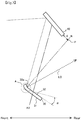
FIG. 3 is a side view showing a transmission-type screen of the HUD device. -
FIG. 4 is a side view showing a modified example of the transmission-type screen of the HUD device. -
FIG. 5 is a view showing a display image displayed on the transmission-type screen shown inFIG. 3 . - A configuration, operation and effects of a HUD device according to an embodiment of the present invention will be specifically described below.
- As shown in
FIG. 1 , theHUD device 1 is provided in a dashboard of a vehicle 2 and reflects a display light L (seeFIG. 2 ) representing a generated display image on awindshield 3 to allow a driver (viewer) to view a virtual image V of the display image representing vehicle information. The driver visually recognizes the display image as a virtual image V in Eyebox 4 that is a range (viewing area) where the display image is visible as a virtual image V. Eyebox 4 is an area defined as a range where the virtual image V is properly visible. It should be noted that the virtual image V inFIG. 1 is schematically shown in order to facilitate a sensory understanding. The same applies to the display light L inFIG. 2 . In the following description, each part constituting theHUD device 1 will be explained as appropriate, assuming that an upward direction is "up", a downward direction as "down", a forward direction as "front", and a rearward direction as "rear" (see arrows at both ends inFIGS. 1 and2 ) as seen from a driver viewing a display image displayed by theHUD device 1. - As shown in
FIG. 2 , theHUD device 1 shown inFIG. 1 includes aprojector 10, a first reflectingmirror 20, a transmission-type screen 30, a second reflectingmirror 40, aconcave mirror 50, acircuit board 60, and ahousing 70. - The
projector 10 is an example of a display light emitting part of the present invention which emits the display light L, indicating a display image under the control of a control unit. The projector comprises, for example, an LED or laser or the like for emitting illumination light, a display device composed of a transmissive display such as a TFT liquid crystal display, a reflective display such as a DMD (Digital Mirror Device) or LCOS (Liquid Crystal On Silicon) for receiving illumination light from a light source to display a display image on a display surface, and a projection lens for emitting the display light L indicating a display image magnified from a display image of the display device. - The first reflecting
mirror 20 is, for example, a plane mirror and reflects the display light L emitted from theprojector 10 toward the transmission-type screen 30. - The transmission-
type screen 30 receives the display light L generated by theprojector 10 on thelight receiving surface 31, and transmits, diffuses and emits the display light L as diffused light to the second reflectingmirror 40 from theemission surface 32. The transmission-type screen 30 is made of a transparent resin such as polycarbonate (PC) or polyethylene terephthalate (PET), and is provided with a grain or microlens on the surface or dispersed diffusion beads inside to obtain a diffusion effect, and is formed in a substantially rectangular shape when viewed from the front. Further, the transmission-type screen 30 is formed and arranged to reflect the external light LO such as sunlight incident into theHUD device 1 in a direction different from that of the secondreflecting mirror 40. Specific shapes and arrangements will be described in detail later. - The second reflecting
mirror 40 is, for example, a plane mirror and reflects the display light L emitted from the transmission-type screen 30 toward theconcave mirror 50. The second reflectingmirror 40 may be a convex mirror or a concave mirror. - The
concave mirror 50 is formed by forming a reflective film on the surface of a concave base made of, for example, a synthetic resin material by means such as vapor deposition, and magnifies the display light L emitted from the transmission-type screen 30 and emits it in the direction of thewindshield 3. - The
circuit board 60 is a printed circuit board, in which a microcomputer including a CPU (Central Processing Unit) and a storage unit such as a ROM (Read Only Memory), and a control unit (not shown) comprising a graphic display controller (GDC) or the like, are mounted on a plate-like substrate made of resin or the like including a glass fiber. Thecircuit board 60 and theprojector 10 are conductively connected by a connecting member (not shown) such as an FPC (Flexible Printed Circuit) and a connector. The control unit acquires vehicle state information such as a vehicle speed and an engine speed transmitted from an external device (not shown) such as a vehicle ECU (Electronic Control Unit) via a communication line, and drives theprojector 10 according to the acquired information (that is, causes theprojector 10 to display a predetermined display image). - The
housing 70 accommodates each member constituting theHUD device 1, and is provided in a hard resin or the like enclosure. Thehousing 70 includes alower case 71 and anupper case 72. Above theupper case 72, there is provided anopening 72 a having a size capable of emitting the display light L reflected by theconcave mirror 50 toward thewindshield 3, and acover glass 73 made of transparent resin is attached to theopening 72 a. - The above is a configuration of the
HUD device 1 according to the present embodiment, and the display light L emitted from theHUD device 1 is projected on thewindshield 3 of the vehicle 2 and incident on the eyes of a driver to allow the driver to visually recognize the virtual image V. In addition, in theHUD device 1, the transmission-type screen 30 has a characteristic configuration and suppresses degradation (washout) of visibility due to external light LO such as sunlight incident from the outside of thewindshield 3. Hereinafter, the specific configuration and the like of the transmission-type screen 30 will be described in detail. - As shown in
FIG. 3 , the transmission-type screen 30 of the present embodiment is disposed to be inclined by a predetermined angle α with respect to an optical axis AX of display light L. This angle α is an angle at which distortion of a virtual image V is minimized (hereinafter also referred to as a minimum distortion angle) in optical design. For example, a minimum distortion angle is 5 to 13 ° in aHUD 1 with a wide angle of view and a distant display in which a field angle of a virtual image V is 10 ° or more in a horizontal direction and 5 ° or more in a vertical direction, and a display distance is about 5 to 10 m. As described above, when the transmission-type screen 30 is inclined with a minimum distortion angle, it is impossible to reflect all of the external light LO incident on theemission surface 32 of the transmission-type screen 30 from the second reflectingmirror 40 in a direction different from that of the second reflectingmirror 40. In detail, the external light LO that has reflected most of the light from the rear end side of theemission surface 32 is directed in a direction different from that of the second reflectingmirror 40. However, unless any measure is taken, the external light LO that has reflected a part of the front-end side (one side of a rectangle) surrounded by the circle A inFIG. 3 is directed toward the second reflectingmirror 40, causing degradation of the visibility of the virtual image V. Standing on this viewpoint, the inventor of the present application reached the idea of making thecurved portion 32 a to incline only a part on the frontend side of theemission surface 32 more than the minimum distortion angle. - The curved surface of the
curved portion 32 a is shaped such that the external light LO reaching from the second reflectingmirror 40 is reflected in a direction different from that of the second reflectingmirror 40. Specifically, it is shaped such that all of the normal N (one normal N is shown as an example inFIG. 3 ) in thecurved portion 32 a are apart from the side end face of the second reflectingmirror 40 by a predetermined distance (for example, 5 mm) or more. As a result, all of the normal N on theemission surface 32 of the transmission-type screen 30 including the portions other than thecurved portion 32 a do not intersect with the second reflectingmirror 40. For example, it is conceivable to design the curved surface shape such that all of the normal N in thecurved portion 32 a passes through a point P having a distance d of 5 mm from the side end surface of the second reflectingmirror 40. According to this criterion, the curved surface shape of thecurved portion 32 a may be a free curved surface, a quadratic curve shape such as a parabola, an ellipse or a hyperbola as viewed from the side. Thecurved portion 32 a of the transmission-type screen 30 and other planar portion (a portion inclined to the minimum distortion angle) are connected by tangent line continuation. Since distortion occurs in the virtual image V by thecurved portion 32 a, it is desirable to minimize the inclination of thecurved portion 32 a. Further, by forming theentire emission surface 32 of the transmission-type screen 30 into a concave curved surface, thecurved portion 32 a may be provided on the front-end side. In this case, as anemission surface 32, a concave curved surface may be formed by moving an original curve in a direction orthogonal to a normal direction of the curve based on a quadratic curve, a cubic curve, or a free curve, or a free-form surface may be formed.FIG. 4 shows a modified example in which the entire transmission-type screen 30 is formed to have an elliptical concave curved surface when viewed from the side. Whichever case the shape of the transmission-type screen 30 is, it is preferable to compare the shapes by optical simulation and select the shape with the least distortion of the virtual image V. - Further, it is desirable to use a flexible material such as the aforementioned transparent resin material in a base of the transmission-
type screen 30 to provide thecurved portion 32 a. In this case, a fixing portion (not shown) provided in thehousing 70 for fixing the transmission-type screen 30 is formed in a concave curved shape for curving the transmission-type screen 30 into an arbitrary shape, whereby thecurved portion 32 a can be easily provided by fixing the transmission-type screen 30 to the fixing portion. In addition, thecurved portion 32 a may be formed by curving at least a part of the transmission-type screen 30 by molding such as thermal processing using a hard-transparent material such as inorganic glass as a base material. - Further, the
emission surface 32 of the transmission-type screen 30 is preferably a smooth surface. In the case where one surface of the transmission-type screen 30 is made rough by surface processing to obtain a diffusion effect, the rough surface serves as thelight receiving surface 31 and the smooth surface as theemission surface 32. If theemission surface 32 is a rough, the external light LO reflected on theemission surface 32 is diffused and the distortion of the virtual image V is increased because of occurrence of the need to increase the inclination angle of the transmission-type screen 30 or to increase the inclination angle of thecurved portion 32 a not to direct the light to the second reflectingmirror 40. - In a display image G displayed on the transmission-
type screen 30 by projecting the display light L from theprojector 10, distortion occurs in thecurved portion 32 a of the transmission-type screen 30 as shown by the hatched portion inFIG. 5 (a) . On the other hand, the display image displayed by theprojector 10 can be corrected by warping which previously distorts the display image in an opposite direction by the amount distorted by thecurved portion 32 a.FIG. 5 (b) shows the display image G, corrected by the warping. As described above, since the warping is a method of correcting the distortion of an image viewed from a specific viewpoint, when a driver's viewpoint moves, the display image G (the virtual image V) returns to the state where the distortion by thecurved portion 32 a is not corrected, but since the distortion only in the hatched portion, that is, in a portion of the display image G is changed, correction by the warping acts relatively effectively. - The
HUD device 1 of the present embodiment is a head-up display device comprises aprojector 10 for emitting display light L that indicates a display image, a transmission-type screen 30 including alight receiving surface 31 for receiving the display light L and anemission surface 32 for emitting the display light L, and a second reflectingmirror 40 for reflecting the display light L from the transmission-type screen 30, wherein the transmission-type screen 30 includes a concavecurved portion 32 a on one end side of theemission surface 32, and thecurved portion 32 a reflects external light LO reaching from the second reflectingmirror 40 in a direction different from that of the second reflectingmirror 40. - According to this, there is no need to incline the transmission-
type screen 30 largely with respect to an optical axis AX of the display light L, and it is possible to reduce distortion of a virtual image V and to prevent degradation of visibility due to the reflected external light LO from the transmission-type screen 30. - Further, in the
HUD device 1, the transmission-type screen 30 is disposed to be inclined by a predetermined angle α with respect to the optical axis AX of the display light L. - According to this, it is possible to minimize the distortion of the virtual image V by inclining the transmission-
type screen 30 to an optically ideal angle. - Further, in the
HUD device 1, theemission surface 32 of the transmission-type screen 30 is a smooth surface. - According to this, the reflected external light LO of the transmission-
type screen 30 does not diffuse, and it is possible to suppress the distortion of the virtual image V by reducing the inclination angle of thecurved portion 32 a and the inclination angle of the entire transmission-type screen 30. - It should be noted that the present invention is not limited to the above-described embodiments, and it is obvious that various modifications (including addition and deletion of constitutional elements) are possible within a range not changing the gist of the invention. In the present embodiment, although the transmission-
type screen 30 is disposed sideways and thecurved portion 32 a is provided on the front-end side of theemission surface 32, one end forming a curved portion is determined by the arrangement of the transmission-type screen and positional relationship with the reflecting mirror, and is not limited to this embodiment. For example, when the transmission-type screen 30 is arranged in a vertical direction, the curved portion is formed on an upper-end side. Further, in the present embodiment, the second reflectingmirror 40 is provided as a reflecting mirror for reflecting the display light L from the transmission-type screen 30, but the reflecting mirror is not limited thereto. For example, in a configuration without the second reflectingmirror 40, theconcave mirror 50 serves as a reflecting mirror that reflects the display light L from the transmission-type screen 30. - The present invention is suitable for a head-up display device using a transmission-type screen.
-
- 1
- Head-up display device
- 10
- Projector (Display light emitting part)
- 20
- First reflecting mirror
- 30
- Transmission-type screen
- 31
- Light receiving surface
- 32
- Emission surface
- 32 a
- Curved portion
- 40
- Second reflecting mirror (reflector)
- 50
- Concave mirror
- G
- Display image
- L
- Display light
- V
- Virtual image
Claims (3)
- A head-up display device, comprising:a display light emitting part for emitting display light that shows a display image;a transmission-type screen, including a light receiving surface that receives the display light and an emission surface that emits the display light; anda reflecting mirror that reflects the display light from the transmission-type screen,wherein the transmission-type screen includes a concave curved portion on one end side of the emission surface, and the curved portion reflects external light reaching from the reflecting mirror in a direction different from that of the reflecting mirror.
- The head-up display device according to claim 1, wherein the transmission-type screen is inclined by a predetermined angle with respect to an optical axis of the display light.
- The head-up display device according to claim 1, wherein the emission surface of the transmission-type screen is a smooth surface.
Applications Claiming Priority (2)
| Application Number | Priority Date | Filing Date | Title |
|---|---|---|---|
| JP2015091248A JP6465353B2 (en) | 2015-04-28 | 2015-04-28 | Head-up display device |
| PCT/JP2016/061965 WO2016175033A1 (en) | 2015-04-28 | 2016-04-14 | Head-up display device |
Publications (3)
| Publication Number | Publication Date |
|---|---|
| EP3290990A1 true EP3290990A1 (en) | 2018-03-07 |
| EP3290990A4 EP3290990A4 (en) | 2018-12-05 |
| EP3290990B1 EP3290990B1 (en) | 2020-07-15 |
Family
ID=57199697
Family Applications (1)
| Application Number | Title | Priority Date | Filing Date |
|---|---|---|---|
| EP16786310.9A Not-in-force EP3290990B1 (en) | 2015-04-28 | 2016-04-14 | Head-up display device |
Country Status (4)
| Country | Link |
|---|---|
| US (1) | US20180101005A1 (en) |
| EP (1) | EP3290990B1 (en) |
| JP (1) | JP6465353B2 (en) |
| WO (1) | WO2016175033A1 (en) |
Cited By (2)
| Publication number | Priority date | Publication date | Assignee | Title |
|---|---|---|---|---|
| DE102017120598A1 (en) * | 2017-09-07 | 2019-03-07 | Valeo Schalter Und Sensoren Gmbh | Head-up display with diffuser for a vehicle |
| WO2019181749A1 (en) * | 2018-03-19 | 2019-09-26 | Ricoh Company, Ltd. | Image projection device and mobile body |
Families Citing this family (11)
| Publication number | Priority date | Publication date | Assignee | Title |
|---|---|---|---|---|
| JPWO2018110336A1 (en) * | 2016-12-13 | 2019-10-24 | コニカミノルタ株式会社 | Head-up display device |
| JP6923322B2 (en) * | 2017-01-18 | 2021-08-18 | デュアリタス リミテッド | Image display device |
| JP7013830B2 (en) * | 2017-01-26 | 2022-02-01 | 日本精機株式会社 | Head-up display device |
| US10746875B2 (en) * | 2017-09-08 | 2020-08-18 | Osram Opto Semiconductors Gmbh | Sensor system and method to operate a sensor system |
| JP2019082601A (en) * | 2017-10-31 | 2019-05-30 | パナソニックIpマネジメント株式会社 | Display system and mobile object |
| US10698209B2 (en) * | 2018-10-11 | 2020-06-30 | E-Lead Electronic Co., Ltd. | Embedded head-up display device |
| CN109581667A (en) * | 2019-01-10 | 2019-04-05 | 延锋伟世通电子科技(上海)有限公司 | A kind of optical projection apparatus for vehicle-mounted head-up display |
| JP7501533B2 (en) * | 2019-07-03 | 2024-06-18 | 日本精機株式会社 | Head-up display device |
| US12181666B2 (en) | 2020-05-25 | 2024-12-31 | Samsung Electronics Co., Ltd. | System of virtual image projection on screen with effect of eliminating influence of solar radiation |
| JP2021073502A (en) * | 2021-01-08 | 2021-05-13 | パナソニックIpマネジメント株式会社 | Display system and movable body |
| EP4163699B1 (en) * | 2021-10-08 | 2025-06-18 | Continental Automotive Technologies GmbH | Head-up display |
Family Cites Families (5)
| Publication number | Priority date | Publication date | Assignee | Title |
|---|---|---|---|---|
| JP5333943B2 (en) * | 2010-03-04 | 2013-11-06 | 日本精機株式会社 | Display device |
| JP5287828B2 (en) * | 2010-10-26 | 2013-09-11 | 株式会社デンソー | Head-up display device |
| JP5370427B2 (en) * | 2011-07-24 | 2013-12-18 | 株式会社デンソー | Head-up display device |
| JP5835128B2 (en) * | 2012-06-29 | 2015-12-24 | 株式会社Jvcケンウッド | Image display device and image display method |
| JP2015059995A (en) * | 2013-09-17 | 2015-03-30 | 株式会社Jvcケンウッド | Image display device |
-
2015
- 2015-04-28 JP JP2015091248A patent/JP6465353B2/en not_active Expired - Fee Related
-
2016
- 2016-04-14 US US15/566,458 patent/US20180101005A1/en not_active Abandoned
- 2016-04-14 EP EP16786310.9A patent/EP3290990B1/en not_active Not-in-force
- 2016-04-14 WO PCT/JP2016/061965 patent/WO2016175033A1/en not_active Ceased
Cited By (4)
| Publication number | Priority date | Publication date | Assignee | Title |
|---|---|---|---|---|
| DE102017120598A1 (en) * | 2017-09-07 | 2019-03-07 | Valeo Schalter Und Sensoren Gmbh | Head-up display with diffuser for a vehicle |
| WO2019181749A1 (en) * | 2018-03-19 | 2019-09-26 | Ricoh Company, Ltd. | Image projection device and mobile body |
| CN111868606A (en) * | 2018-03-19 | 2020-10-30 | 株式会社理光 | Image projection apparatus and moving body |
| CN111868606B (en) * | 2018-03-19 | 2022-09-20 | 株式会社理光 | Image projection apparatus and moving body |
Also Published As
| Publication number | Publication date |
|---|---|
| WO2016175033A1 (en) | 2016-11-03 |
| JP6465353B2 (en) | 2019-02-06 |
| EP3290990A4 (en) | 2018-12-05 |
| US20180101005A1 (en) | 2018-04-12 |
| JP2016206583A (en) | 2016-12-08 |
| EP3290990B1 (en) | 2020-07-15 |
Similar Documents
| Publication | Publication Date | Title |
|---|---|---|
| EP3290990B1 (en) | Head-up display device | |
| CN107238927B (en) | Projection display equipment for vehicles | |
| JP5287828B2 (en) | Head-up display device | |
| TWI541543B (en) | Beam splitting module and projector device using the same | |
| US20180252917A1 (en) | Display Image Projection Apparatus and Display Image Projection System | |
| US20180252918A1 (en) | Display Image Projection System | |
| US20190317322A1 (en) | Head-up display device | |
| US10634909B2 (en) | Display device and head-up display | |
| JP2015161732A (en) | Display light projection optical device | |
| CN112005154B (en) | Head-up display and moving object having head-up display mounted thereon | |
| US20210063736A1 (en) | Headup display device | |
| JP7287394B2 (en) | head-up display device | |
| JP2018180291A (en) | Vehicle display device | |
| JP2017142284A (en) | Display device and head-up display | |
| JP6611310B2 (en) | Projection display device for vehicle | |
| US12072488B2 (en) | Display device, head-up display, and mobile object | |
| CN217506280U (en) | Head-up display device | |
| JP7535084B2 (en) | Head-up display device | |
| JP7826203B2 (en) | Image generating device and head-up display | |
| JP6958558B2 (en) | Virtual image display device | |
| JP7357233B2 (en) | heads up display | |
| KR20190042318A (en) | Head-up display device | |
| KR102337698B1 (en) | Head-up display device | |
| KR20180101001A (en) | Screen structure of optical device for projector type-head up display and optical device for projector type-head up display including the screen structure |
Legal Events
| Date | Code | Title | Description |
|---|---|---|---|
| STAA | Information on the status of an ep patent application or granted ep patent |
Free format text: STATUS: THE INTERNATIONAL PUBLICATION HAS BEEN MADE |
|
| PUAI | Public reference made under article 153(3) epc to a published international application that has entered the european phase |
Free format text: ORIGINAL CODE: 0009012 |
|
| STAA | Information on the status of an ep patent application or granted ep patent |
Free format text: STATUS: REQUEST FOR EXAMINATION WAS MADE |
|
| 17P | Request for examination filed |
Effective date: 20171012 |
|
| AK | Designated contracting states |
Kind code of ref document: A1 Designated state(s): AL AT BE BG CH CY CZ DE DK EE ES FI FR GB GR HR HU IE IS IT LI LT LU LV MC MK MT NL NO PL PT RO RS SE SI SK SM TR |
|
| AX | Request for extension of the european patent |
Extension state: BA ME |
|
| DAV | Request for validation of the european patent (deleted) | ||
| DAX | Request for extension of the european patent (deleted) | ||
| RIC1 | Information provided on ipc code assigned before grant |
Ipc: B60K 35/00 20060101ALI20181018BHEP Ipc: H04N 5/64 20060101ALI20181018BHEP Ipc: G02B 27/01 20060101AFI20181018BHEP |
|
| A4 | Supplementary search report drawn up and despatched |
Effective date: 20181026 |
|
| GRAP | Despatch of communication of intention to grant a patent |
Free format text: ORIGINAL CODE: EPIDOSNIGR1 |
|
| STAA | Information on the status of an ep patent application or granted ep patent |
Free format text: STATUS: GRANT OF PATENT IS INTENDED |
|
| INTG | Intention to grant announced |
Effective date: 20200402 |
|
| GRAS | Grant fee paid |
Free format text: ORIGINAL CODE: EPIDOSNIGR3 |
|
| GRAA | (expected) grant |
Free format text: ORIGINAL CODE: 0009210 |
|
| STAA | Information on the status of an ep patent application or granted ep patent |
Free format text: STATUS: THE PATENT HAS BEEN GRANTED |
|
| AK | Designated contracting states |
Kind code of ref document: B1 Designated state(s): AL AT BE BG CH CY CZ DE DK EE ES FI FR GB GR HR HU IE IS IT LI LT LU LV MC MK MT NL NO PL PT RO RS SE SI SK SM TR |
|
| REG | Reference to a national code |
Ref country code: CH Ref legal event code: EP Ref country code: GB Ref legal event code: FG4D |
|
| REG | Reference to a national code |
Ref country code: IE Ref legal event code: FG4D |
|
| REG | Reference to a national code |
Ref country code: DE Ref legal event code: R096 Ref document number: 602016040037 Country of ref document: DE |
|
| REG | Reference to a national code |
Ref country code: AT Ref legal event code: REF Ref document number: 1291667 Country of ref document: AT Kind code of ref document: T Effective date: 20200815 |
|
| REG | Reference to a national code |
Ref country code: LT Ref legal event code: MG4D |
|
| REG | Reference to a national code |
Ref country code: AT Ref legal event code: MK05 Ref document number: 1291667 Country of ref document: AT Kind code of ref document: T Effective date: 20200715 |
|
| REG | Reference to a national code |
Ref country code: NL Ref legal event code: MP Effective date: 20200715 |
|
| PG25 | Lapsed in a contracting state [announced via postgrant information from national office to epo] |
Ref country code: FI Free format text: LAPSE BECAUSE OF FAILURE TO SUBMIT A TRANSLATION OF THE DESCRIPTION OR TO PAY THE FEE WITHIN THE PRESCRIBED TIME-LIMIT Effective date: 20200715 Ref country code: GR Free format text: LAPSE BECAUSE OF FAILURE TO SUBMIT A TRANSLATION OF THE DESCRIPTION OR TO PAY THE FEE WITHIN THE PRESCRIBED TIME-LIMIT Effective date: 20201016 Ref country code: NO Free format text: LAPSE BECAUSE OF FAILURE TO SUBMIT A TRANSLATION OF THE DESCRIPTION OR TO PAY THE FEE WITHIN THE PRESCRIBED TIME-LIMIT Effective date: 20201015 Ref country code: HR Free format text: LAPSE BECAUSE OF FAILURE TO SUBMIT A TRANSLATION OF THE DESCRIPTION OR TO PAY THE FEE WITHIN THE PRESCRIBED TIME-LIMIT Effective date: 20200715 Ref country code: PT Free format text: LAPSE BECAUSE OF FAILURE TO SUBMIT A TRANSLATION OF THE DESCRIPTION OR TO PAY THE FEE WITHIN THE PRESCRIBED TIME-LIMIT Effective date: 20201116 Ref country code: SE Free format text: LAPSE BECAUSE OF FAILURE TO SUBMIT A TRANSLATION OF THE DESCRIPTION OR TO PAY THE FEE WITHIN THE PRESCRIBED TIME-LIMIT Effective date: 20200715 Ref country code: AT Free format text: LAPSE BECAUSE OF FAILURE TO SUBMIT A TRANSLATION OF THE DESCRIPTION OR TO PAY THE FEE WITHIN THE PRESCRIBED TIME-LIMIT Effective date: 20200715 Ref country code: ES Free format text: LAPSE BECAUSE OF FAILURE TO SUBMIT A TRANSLATION OF THE DESCRIPTION OR TO PAY THE FEE WITHIN THE PRESCRIBED TIME-LIMIT Effective date: 20200715 Ref country code: BG Free format text: LAPSE BECAUSE OF FAILURE TO SUBMIT A TRANSLATION OF THE DESCRIPTION OR TO PAY THE FEE WITHIN THE PRESCRIBED TIME-LIMIT Effective date: 20201015 Ref country code: LT Free format text: LAPSE BECAUSE OF FAILURE TO SUBMIT A TRANSLATION OF THE DESCRIPTION OR TO PAY THE FEE WITHIN THE PRESCRIBED TIME-LIMIT Effective date: 20200715 |
|
| PG25 | Lapsed in a contracting state [announced via postgrant information from national office to epo] |
Ref country code: PL Free format text: LAPSE BECAUSE OF FAILURE TO SUBMIT A TRANSLATION OF THE DESCRIPTION OR TO PAY THE FEE WITHIN THE PRESCRIBED TIME-LIMIT Effective date: 20200715 Ref country code: LV Free format text: LAPSE BECAUSE OF FAILURE TO SUBMIT A TRANSLATION OF THE DESCRIPTION OR TO PAY THE FEE WITHIN THE PRESCRIBED TIME-LIMIT Effective date: 20200715 Ref country code: RS Free format text: LAPSE BECAUSE OF FAILURE TO SUBMIT A TRANSLATION OF THE DESCRIPTION OR TO PAY THE FEE WITHIN THE PRESCRIBED TIME-LIMIT Effective date: 20200715 Ref country code: IS Free format text: LAPSE BECAUSE OF FAILURE TO SUBMIT A TRANSLATION OF THE DESCRIPTION OR TO PAY THE FEE WITHIN THE PRESCRIBED TIME-LIMIT Effective date: 20201115 |
|
| PG25 | Lapsed in a contracting state [announced via postgrant information from national office to epo] |
Ref country code: NL Free format text: LAPSE BECAUSE OF FAILURE TO SUBMIT A TRANSLATION OF THE DESCRIPTION OR TO PAY THE FEE WITHIN THE PRESCRIBED TIME-LIMIT Effective date: 20200715 |
|
| REG | Reference to a national code |
Ref country code: DE Ref legal event code: R097 Ref document number: 602016040037 Country of ref document: DE |
|
| PG25 | Lapsed in a contracting state [announced via postgrant information from national office to epo] |
Ref country code: IT Free format text: LAPSE BECAUSE OF FAILURE TO SUBMIT A TRANSLATION OF THE DESCRIPTION OR TO PAY THE FEE WITHIN THE PRESCRIBED TIME-LIMIT Effective date: 20200715 Ref country code: EE Free format text: LAPSE BECAUSE OF FAILURE TO SUBMIT A TRANSLATION OF THE DESCRIPTION OR TO PAY THE FEE WITHIN THE PRESCRIBED TIME-LIMIT Effective date: 20200715 Ref country code: SM Free format text: LAPSE BECAUSE OF FAILURE TO SUBMIT A TRANSLATION OF THE DESCRIPTION OR TO PAY THE FEE WITHIN THE PRESCRIBED TIME-LIMIT Effective date: 20200715 Ref country code: DK Free format text: LAPSE BECAUSE OF FAILURE TO SUBMIT A TRANSLATION OF THE DESCRIPTION OR TO PAY THE FEE WITHIN THE PRESCRIBED TIME-LIMIT Effective date: 20200715 Ref country code: CZ Free format text: LAPSE BECAUSE OF FAILURE TO SUBMIT A TRANSLATION OF THE DESCRIPTION OR TO PAY THE FEE WITHIN THE PRESCRIBED TIME-LIMIT Effective date: 20200715 Ref country code: RO Free format text: LAPSE BECAUSE OF FAILURE TO SUBMIT A TRANSLATION OF THE DESCRIPTION OR TO PAY THE FEE WITHIN THE PRESCRIBED TIME-LIMIT Effective date: 20200715 |
|
| PLBE | No opposition filed within time limit |
Free format text: ORIGINAL CODE: 0009261 |
|
| STAA | Information on the status of an ep patent application or granted ep patent |
Free format text: STATUS: NO OPPOSITION FILED WITHIN TIME LIMIT |
|
| PG25 | Lapsed in a contracting state [announced via postgrant information from national office to epo] |
Ref country code: AL Free format text: LAPSE BECAUSE OF FAILURE TO SUBMIT A TRANSLATION OF THE DESCRIPTION OR TO PAY THE FEE WITHIN THE PRESCRIBED TIME-LIMIT Effective date: 20200715 |
|
| 26N | No opposition filed |
Effective date: 20210416 |
|
| PG25 | Lapsed in a contracting state [announced via postgrant information from national office to epo] |
Ref country code: SK Free format text: LAPSE BECAUSE OF FAILURE TO SUBMIT A TRANSLATION OF THE DESCRIPTION OR TO PAY THE FEE WITHIN THE PRESCRIBED TIME-LIMIT Effective date: 20200715 |
|
| PGFP | Annual fee paid to national office [announced via postgrant information from national office to epo] |
Ref country code: DE Payment date: 20210316 Year of fee payment: 6 |
|
| PG25 | Lapsed in a contracting state [announced via postgrant information from national office to epo] |
Ref country code: SI Free format text: LAPSE BECAUSE OF FAILURE TO SUBMIT A TRANSLATION OF THE DESCRIPTION OR TO PAY THE FEE WITHIN THE PRESCRIBED TIME-LIMIT Effective date: 20200715 |
|
| PG25 | Lapsed in a contracting state [announced via postgrant information from national office to epo] |
Ref country code: MC Free format text: LAPSE BECAUSE OF FAILURE TO SUBMIT A TRANSLATION OF THE DESCRIPTION OR TO PAY THE FEE WITHIN THE PRESCRIBED TIME-LIMIT Effective date: 20200715 |
|
| GBPC | Gb: european patent ceased through non-payment of renewal fee |
Effective date: 20210414 |
|
| PG25 | Lapsed in a contracting state [announced via postgrant information from national office to epo] |
Ref country code: LU Free format text: LAPSE BECAUSE OF NON-PAYMENT OF DUE FEES Effective date: 20210414 |
|
| REG | Reference to a national code |
Ref country code: BE Ref legal event code: MM Effective date: 20210430 |
|
| PG25 | Lapsed in a contracting state [announced via postgrant information from national office to epo] |
Ref country code: LI Free format text: LAPSE BECAUSE OF NON-PAYMENT OF DUE FEES Effective date: 20210430 Ref country code: CH Free format text: LAPSE BECAUSE OF NON-PAYMENT OF DUE FEES Effective date: 20210430 Ref country code: FR Free format text: LAPSE BECAUSE OF NON-PAYMENT OF DUE FEES Effective date: 20210430 Ref country code: GB Free format text: LAPSE BECAUSE OF NON-PAYMENT OF DUE FEES Effective date: 20210414 |
|
| PG25 | Lapsed in a contracting state [announced via postgrant information from national office to epo] |
Ref country code: IE Free format text: LAPSE BECAUSE OF NON-PAYMENT OF DUE FEES Effective date: 20210414 |
|
| PG25 | Lapsed in a contracting state [announced via postgrant information from national office to epo] |
Ref country code: IS Free format text: LAPSE BECAUSE OF FAILURE TO SUBMIT A TRANSLATION OF THE DESCRIPTION OR TO PAY THE FEE WITHIN THE PRESCRIBED TIME-LIMIT Effective date: 20201115 |
|
| PG25 | Lapsed in a contracting state [announced via postgrant information from national office to epo] |
Ref country code: BE Free format text: LAPSE BECAUSE OF NON-PAYMENT OF DUE FEES Effective date: 20210430 |
|
| REG | Reference to a national code |
Ref country code: DE Ref legal event code: R119 Ref document number: 602016040037 Country of ref document: DE |
|
| PG25 | Lapsed in a contracting state [announced via postgrant information from national office to epo] |
Ref country code: DE Free format text: LAPSE BECAUSE OF NON-PAYMENT OF DUE FEES Effective date: 20221103 |
|
| PG25 | Lapsed in a contracting state [announced via postgrant information from national office to epo] |
Ref country code: HU Free format text: LAPSE BECAUSE OF FAILURE TO SUBMIT A TRANSLATION OF THE DESCRIPTION OR TO PAY THE FEE WITHIN THE PRESCRIBED TIME-LIMIT; INVALID AB INITIO Effective date: 20160414 |
|
| PG25 | Lapsed in a contracting state [announced via postgrant information from national office to epo] |
Ref country code: CY Free format text: LAPSE BECAUSE OF FAILURE TO SUBMIT A TRANSLATION OF THE DESCRIPTION OR TO PAY THE FEE WITHIN THE PRESCRIBED TIME-LIMIT Effective date: 20200715 |
|
| PG25 | Lapsed in a contracting state [announced via postgrant information from national office to epo] |
Ref country code: MK Free format text: LAPSE BECAUSE OF FAILURE TO SUBMIT A TRANSLATION OF THE DESCRIPTION OR TO PAY THE FEE WITHIN THE PRESCRIBED TIME-LIMIT Effective date: 20200715 |
|
| PG25 | Lapsed in a contracting state [announced via postgrant information from national office to epo] |
Ref country code: TR Free format text: LAPSE BECAUSE OF FAILURE TO SUBMIT A TRANSLATION OF THE DESCRIPTION OR TO PAY THE FEE WITHIN THE PRESCRIBED TIME-LIMIT Effective date: 20200715 |
|
| PG25 | Lapsed in a contracting state [announced via postgrant information from national office to epo] |
Ref country code: MT Free format text: LAPSE BECAUSE OF FAILURE TO SUBMIT A TRANSLATION OF THE DESCRIPTION OR TO PAY THE FEE WITHIN THE PRESCRIBED TIME-LIMIT Effective date: 20200715 |