EP3290735A1 - Brake discs - Google Patents
Brake discs Download PDFInfo
- Publication number
- EP3290735A1 EP3290735A1 EP17250006.8A EP17250006A EP3290735A1 EP 3290735 A1 EP3290735 A1 EP 3290735A1 EP 17250006 A EP17250006 A EP 17250006A EP 3290735 A1 EP3290735 A1 EP 3290735A1
- Authority
- EP
- European Patent Office
- Prior art keywords
- flange
- hub
- brake disc
- wall
- friction ring
- Prior art date
- Legal status (The legal status is an assumption and is not a legal conclusion. Google has not performed a legal analysis and makes no representation as to the accuracy of the status listed.)
- Granted
Links
Images










Classifications
-
- F—MECHANICAL ENGINEERING; LIGHTING; HEATING; WEAPONS; BLASTING
- F16—ENGINEERING ELEMENTS AND UNITS; GENERAL MEASURES FOR PRODUCING AND MAINTAINING EFFECTIVE FUNCTIONING OF MACHINES OR INSTALLATIONS; THERMAL INSULATION IN GENERAL
- F16D—COUPLINGS FOR TRANSMITTING ROTATION; CLUTCHES; BRAKES
- F16D65/00—Parts or details
- F16D65/02—Braking members; Mounting thereof
- F16D65/12—Discs; Drums for disc brakes
- F16D65/123—Discs; Drums for disc brakes comprising an annular disc secured to a hub member; Discs characterised by means for mounting
-
- B—PERFORMING OPERATIONS; TRANSPORTING
- B22—CASTING; POWDER METALLURGY
- B22D—CASTING OF METALS; CASTING OF OTHER SUBSTANCES BY THE SAME PROCESSES OR DEVICES
- B22D19/00—Casting in, on, or around objects which form part of the product
-
- F—MECHANICAL ENGINEERING; LIGHTING; HEATING; WEAPONS; BLASTING
- F16—ENGINEERING ELEMENTS AND UNITS; GENERAL MEASURES FOR PRODUCING AND MAINTAINING EFFECTIVE FUNCTIONING OF MACHINES OR INSTALLATIONS; THERMAL INSULATION IN GENERAL
- F16D—COUPLINGS FOR TRANSMITTING ROTATION; CLUTCHES; BRAKES
- F16D65/00—Parts or details
- F16D65/02—Braking members; Mounting thereof
- F16D2065/13—Parts or details of discs or drums
- F16D2065/1304—Structure
- F16D2065/1324—Structure carrying friction elements
-
- F—MECHANICAL ENGINEERING; LIGHTING; HEATING; WEAPONS; BLASTING
- F16—ENGINEERING ELEMENTS AND UNITS; GENERAL MEASURES FOR PRODUCING AND MAINTAINING EFFECTIVE FUNCTIONING OF MACHINES OR INSTALLATIONS; THERMAL INSULATION IN GENERAL
- F16D—COUPLINGS FOR TRANSMITTING ROTATION; CLUTCHES; BRAKES
- F16D65/00—Parts or details
- F16D65/02—Braking members; Mounting thereof
- F16D2065/13—Parts or details of discs or drums
- F16D2065/134—Connection
- F16D2065/1344—Connection permanent, e.g. by casting
-
- F—MECHANICAL ENGINEERING; LIGHTING; HEATING; WEAPONS; BLASTING
- F16—ENGINEERING ELEMENTS AND UNITS; GENERAL MEASURES FOR PRODUCING AND MAINTAINING EFFECTIVE FUNCTIONING OF MACHINES OR INSTALLATIONS; THERMAL INSULATION IN GENERAL
- F16D—COUPLINGS FOR TRANSMITTING ROTATION; CLUTCHES; BRAKES
- F16D65/00—Parts or details
- F16D65/02—Braking members; Mounting thereof
- F16D2065/13—Parts or details of discs or drums
- F16D2065/134—Connection
- F16D2065/1348—Connection resilient
-
- F—MECHANICAL ENGINEERING; LIGHTING; HEATING; WEAPONS; BLASTING
- F16—ENGINEERING ELEMENTS AND UNITS; GENERAL MEASURES FOR PRODUCING AND MAINTAINING EFFECTIVE FUNCTIONING OF MACHINES OR INSTALLATIONS; THERMAL INSULATION IN GENERAL
- F16D—COUPLINGS FOR TRANSMITTING ROTATION; CLUTCHES; BRAKES
- F16D65/00—Parts or details
- F16D65/02—Braking members; Mounting thereof
- F16D2065/13—Parts or details of discs or drums
- F16D2065/134—Connection
- F16D2065/1356—Connection interlocking
-
- F—MECHANICAL ENGINEERING; LIGHTING; HEATING; WEAPONS; BLASTING
- F16—ENGINEERING ELEMENTS AND UNITS; GENERAL MEASURES FOR PRODUCING AND MAINTAINING EFFECTIVE FUNCTIONING OF MACHINES OR INSTALLATIONS; THERMAL INSULATION IN GENERAL
- F16D—COUPLINGS FOR TRANSMITTING ROTATION; CLUTCHES; BRAKES
- F16D65/00—Parts or details
- F16D65/02—Braking members; Mounting thereof
- F16D2065/13—Parts or details of discs or drums
- F16D2065/134—Connection
- F16D2065/1376—Connection inner circumference
-
- F—MECHANICAL ENGINEERING; LIGHTING; HEATING; WEAPONS; BLASTING
- F16—ENGINEERING ELEMENTS AND UNITS; GENERAL MEASURES FOR PRODUCING AND MAINTAINING EFFECTIVE FUNCTIONING OF MACHINES OR INSTALLATIONS; THERMAL INSULATION IN GENERAL
- F16D—COUPLINGS FOR TRANSMITTING ROTATION; CLUTCHES; BRAKES
- F16D65/00—Parts or details
- F16D65/02—Braking members; Mounting thereof
- F16D2065/13—Parts or details of discs or drums
- F16D2065/134—Connection
- F16D2065/1392—Connection elements
-
- F—MECHANICAL ENGINEERING; LIGHTING; HEATING; WEAPONS; BLASTING
- F16—ENGINEERING ELEMENTS AND UNITS; GENERAL MEASURES FOR PRODUCING AND MAINTAINING EFFECTIVE FUNCTIONING OF MACHINES OR INSTALLATIONS; THERMAL INSULATION IN GENERAL
- F16D—COUPLINGS FOR TRANSMITTING ROTATION; CLUTCHES; BRAKES
- F16D2200/00—Materials; Production methods therefor
- F16D2200/0004—Materials; Production methods therefor metallic
- F16D2200/0008—Ferro
- F16D2200/0013—Cast iron
-
- F—MECHANICAL ENGINEERING; LIGHTING; HEATING; WEAPONS; BLASTING
- F16—ENGINEERING ELEMENTS AND UNITS; GENERAL MEASURES FOR PRODUCING AND MAINTAINING EFFECTIVE FUNCTIONING OF MACHINES OR INSTALLATIONS; THERMAL INSULATION IN GENERAL
- F16D—COUPLINGS FOR TRANSMITTING ROTATION; CLUTCHES; BRAKES
- F16D2200/00—Materials; Production methods therefor
- F16D2200/0004—Materials; Production methods therefor metallic
- F16D2200/0026—Non-ferro
- F16D2200/003—Light metals, e.g. aluminium
-
- F—MECHANICAL ENGINEERING; LIGHTING; HEATING; WEAPONS; BLASTING
- F16—ENGINEERING ELEMENTS AND UNITS; GENERAL MEASURES FOR PRODUCING AND MAINTAINING EFFECTIVE FUNCTIONING OF MACHINES OR INSTALLATIONS; THERMAL INSULATION IN GENERAL
- F16D—COUPLINGS FOR TRANSMITTING ROTATION; CLUTCHES; BRAKES
- F16D2250/00—Manufacturing; Assembly
- F16D2250/0007—Casting
Definitions
- This invention concerns brake discs, particularly but not necessarily exclusively brake discs for high performance motor vehicles such as sports cars.
- a brake disc of a vehicle comprises a rotor comprising a friction ring that rotates with a ground-engaging wheel of the vehicle and is gripped by caliper-operated pads to slow the vehicle down when required.
- the friction ring must be able to resist both wear from the brake pads and heat generated by the braking.
- brake disc rotors are conventionally made of cast iron.
- cast iron is a relatively heavy material for use in a sports car: it is, for instance, about two and a half times as heavy as aluminium. Therefore, to reduce the weight of the disc brake as a whole, the friction ring may be carried on a hub formed of lighter material such as aluminium or an aluminium alloy.
- the hub sometimes known as a mounting bell or a "top hat", is in use connected to a ground-engaging wheel or an axle of the wheel.
- a friction ring of cast iron may be connected to a substantially lighter cast light-aluminium or deep-drawn sheet-steel brake-disc hub. Spigots on the friction ring engage in associated recesses in the hub to transmit rotational forces and a retaining ring secures the joint against transverse (axial) forces, but additional screw connections are also recommended.
- the retaining ring and screw connections necessarily add to the complexity of such an arrangement, and a simpler arrangement is to be preferred.
- European patent application EP1426644 describes a composite brake disc in which a rotor comprising grey cast iron has cast onto it a hub section comprising aluminium with a geometric coupling called a "form-fit" connection (formschlüssige Beth) between them to deal with the rotational and transverse forces in use.
- This form-fit connection comprises circumferentially spaced axially-extending teeth on the rotor that are received in axial seats in the hub section and circumferentially spaced radially-extending teeth on the rotor that are received in radial seats in the hub section.
- European patent application EP3081826 describes a composite brake disc in which a rotor comprising grey cast iron has cast onto it a hub comprising aluminium with a connection between the rotor and the hub that comprises circumferentially spaced axial teeth (but not radial teeth) and in which the hub is a shrink-fit on the rotor.
- This is a simpler and therefore cheaper arrangement than that of EP1426644 and it also has the advantage of preventing even small relative movements between the rotor and the hub which are admitted in EP1426644 and are undesirable.
- the present invention provides improvements over EP3081826 .
- a brake disc for a vehicle which brake disc comprises:
- An important benefit of configuring and arranging the encapsulated portion of the wall so as to permit differential thermal expansion of the hub relative to the flange as the hub solidifies and cool after its casting is that it minimises retained stresses in the hub. This can be achieved even though, as is preferred, the hub is a shrink-fit on the flange.
- the encapsulated portion of the wall may be formed with axially-extending (but not radially-extending) teeth and it may be made smooth, eg by a machining operation such as turning or honing.
- a machining operation such as turning or honing.
- the flange may have a radial dimension which varies along its axial extent.
- the encapsulated portion of the wall may be formed with a screw thread extending helically about the axis of rotation (to allow differential thermal contraction of the hub along the helical path of the thread).
- a brake disc for a motor vehicle comprising:
- the threads prevent axial separation of the mounting bell and the flange, and the use of threads of opposite handedness facilitates torque transmission in forward and reverse directions of rotation without risk of the mounting bell unscrewing.
- a third aspect of the invention there is provided a method of manufacturing a according to the first aspect of the invention, which method comprises the steps of:
- the prior art brake disc of Figures 1 to 4 comprises a rotor indicated at 10 and a hub indicated generally at 12.
- the rotor 10 comprises a friction ring 14 annular about an axis 16, being the axis of rotation of a road wheel or axle, not shown.
- a tubular flange 18 extends axially from the friction ring 14 to a free end 18a ( Figure 3 ).
- the friction ring 14 extends radially from an inner radius 10a to an outer radius 10b, the inner radius being coterminous with the inside of the hollow cylindrical flange 18.
- the friction ring 14 and the flange 18 are integrally formed from grey cast iron by casting and machining.
- the hub 12 is formed by casting from aluminium (or aluminium alloy) and as can be seen most clearly from Figure 3 the casting extends axially over part of the radially inner and the radially outer faces of the flange 18. That is to say, the casting of the hub 12 encapsulates a portion of the flange 18 and engages radially inner and outer surfaces of the flange 18 and thereby makes a connection between the hub 12 and the rotor 10.
- the hub 12 is a shrink fit upon the encapsulated portion of the flange 18.
- the flange 18 is formed with circumferentially spaced axially-extending teeth 18b encapsulated in the casting of the hub 12. (For simplicity of illustration, only a few teeth 18a are shown in Figure 4 , and in practice there may be more).
- the brake disc of Figures 5 to 8 comprises a rotor indicated at 20 and a hub indicated generally at 22.
- the rotor 20 comprises a friction ring 24 annular about an axis 26, being the axis of rotation of a road wheel or axle, not shown.
- a tubular flange 28 extends axially from the friction ring 24 to a free end 28a ( Figure 3 ).
- the friction ring 24 and the flange 28 are integrally formed from grey cast iron by casting and machining.
- the hub 22 is formed by casting from aluminium (or aluminium alloy) and as can be seen most clearly from Figure 3 the casting extends axially over part of the radially inner face 28c and the radially outer face 28d of the flange 28 radially bounding the wall 28e of the flange 28. That is to say, the casting of the hub 12 encapsulates a portion of the flange wall 28e and by engaging the radially inner face 28c and the radially outer face 28d of the flange 18 makes a connection between the hub 22 and the rotor 20.
- the hub 22 is a shrink fit upon the encapsulated portion of the wall 28e.
- the flange 28 is formed at its free end with circumferentially spaced axially-extending teeth 28b encapsulated in the casting of the hub 22.
- the brake disc of Figures 5 to 8 is essentially the same as the prior art brake disc of Figures 1 to 4 . But there is an important underlying difference. This is that the inner and outer surfaces 28c and 28d of the flange wall 28e are both made smooth. This is done by turning or honing etc during the machining of the rotor and its effect is to minimise retained stresses in the hub 22, as will now be explained.
- the hub 22 contracts as it solidifies after casting, and carries on contracting relative to the rotor 20 as it cools after casting, the aluminium of the hub 22 having a substantially greater coefficient of thermal expansion than the grey cast iron of the rotor 20.
- the smooth surfaces 28c and 28d allow the relatively contracting hub 22 to retract along the wall 28e of the flange 28, whereby retained stresses in the hub 22 are minimised.
- the geometry of the interface between the hub 22 and the wall 28e is such that the hub 22 can contract as it cools without geometric resistance imposed by the rotor 20 and without weakening of the interface as the hub 22 cools and contacts.
- the iron rotor 20 is preheated before the aluminium hub 22 is cast upon it, so it also contracts during the cooling process, but to a lesser degree than the hub 22.
- the encapsulated teeth 28b at the free end 28a of the flange 28 positively resist rotational forces in use of the brake disc of Figure 5 to 8 .
- the term "positively resist” and related terms used herein should be understood to mean that there is a physical barrier to movement in the direction of the forces applied, and not just a gripping resistance from the shrink-fit connection). It is advisable to provide similarly positive resistance to axial forces. This can be achieved in the present invention without comprising the need to avoid an untoward build-up of retained stresses in the hub, as will now be described firstly with reference to Figures 9 to 11 .
- a brake disc rotor 30 comprises a friction ring 34 annular about an axis 36, being the axis of rotation of a road wheel or axle, not shown.
- a tubular flange 38 extends axially from the friction ring 34 to a free end 38a.
- the friction ring 34 and the flange 38 are integrally formed from grey cast iron by casting and machining.
- the radially inner face 38c and the radially outer surface 38d that bound the wall 38e are both made smooth, as in the arrangement of Figures 5 to 8 .
- the radial thickness t of the wall 38e increases towards the free end 38a of the flange 38.
- the variation in the radial thickness t of the flange wall 38e is provided by sloping the inner face 38c radially inwardly towards the free end 38a of the flange 38.
- the outer face 38d may be sloped radially outwardly towards the free end 38a instead of or as well as having the inner face 38c sloping radially inwardly towards the free end 38a.
- Figures 12 and 13 illustrate other ways in which variation in a radial dimension of the flange along its axial extent can be arranged to provide positive resistance to axial forces.
- a brake disc rotor 40 comprises a friction ring 44 annular about an axis 46, being the axis of rotation of a road wheel or axle, not shown.
- a tubular flange 48 extends axially from the friction ring 44 to a free end 48a and the friction ring 44 and the flange 48 are integrally formed from grey cast iron by casting and machining.
- the radially inner face 48c and the radially outer surface 48d that bound the wall 48e of the flange 48 are both made smooth, as in the arrangement of Figures 9 to 11 .
- a brake disc rotor 50 comprises a friction ring 54 annular about an axis 56, being the axis of rotation of a road wheel or axle, not shown.
- a tubular flange 58 extends axially from the friction ring 54 to a free end 58a and the friction ring 54 and the flange 58 are integrally formed from grey cast iron by casting and machining.
- the radially inner face 58c and the radially outer surface 58d that bound the wall 58e of the flange 58 are both made smooth, as in the arrangement of Figure 12 .
- the diameter d of the flange 58 decreases towards its free end 58a rather than increasing. This increasing diameter (which may be combined with increasing wall thickness) provides positive resistance to axial forces on the hub (not shown in Figure 13 ) without compromising the need to avoid an untoward build-up of retained stresses in the hub.
- a brake disc rotor 60 comprises a friction ring 64 annular about an axis 36, being the axis of rotation of a road wheel or axle, not shown.
- a tubular flange 68 extends axially from the friction ring 64 to a free end 68a.
- the friction ring 64 and the flange 68 are integrally formed from grey cast iron by casting and machining. Rather than simply being made smooth as in the arrangement of Figures 5 to 8 , however, in the arrangement of Figures 14 to 17 the radially inner face 68c and the radially outer surface 68d of the flange 68 are respectively formed with screw threads 68f and 68g. (It should be understood that the depictions of the screw threads in the drawings are stylised and exaggerated for clarity of illustration).
- the hub (not shown) is cast over the screw threads 68f and 68g and by their helical form these screw threads permit differential thermal contraction, in an axial direction, of the hub relative to the flange 68 as the hub solidifies and cools after casting. But when the cast hub has solidified and cooled, the screw threads prevent its being pulled axially off the flange.
- the arrangement of Figures 14 to 16 provides positive resistance to axial separation of the hub relative to the flange without compromising the need to avoid an untoward build-up of retained stresses in the hub.
- a single screw thread on the radially inner face 68c or the radially outer face 68d will be sufficient to provide a positive resistance to axial movement of the hub relative to the friction ring. Otherwise, where abnormally high axially forces are expected, eg on a race track, the positive resistance of the two screw threads can be increased by forming them with mutually opposite hands - with the inner screw thread 68c having a righthand thread and the outer screw thread 68d having a left-hand thread, or vice versa.
- the screw thread form used in the invention is a stub Acme thread.
- a trapezoidal form like the Acme thread is used because it is relatively easy to cut (compared with say a square thread) and relatively strong, having a wide base. This applies more so to the stub Acme form, inasmuch as this has a lower depth. And known problems in disassembling the stub Acme thread are not relevant in this use.
- the rotor 70 has a spiral screw thread 72 formed on the free end of the axially-extending tubular flange 74.
- the screw thread 72 functions like the axially extending teeth 28b of the arrangement illustrated by Figures 5 to 8 in that it is encapsulated by the hub (not shown in Figure 16 ) when the hub is cast onto the rotor 70 to be a shrink fit thereon.
- the rotor 80 has a tubular flange 82 extending axially from it that has a diameter that reduces towards its free end 82a.
- Helical screw threads 84 and 86 are formed on the inner and outer faces of the flange 82.
- the rotor 90 includes an axially extending flange 92 with a wall of greater radial thickness than the flanges illustrated by the other drawings hereof.
- the greater radial thickness accommodates an annular channel 94 with helical screw threads 96 and 98 formed in the inner and outer cylindrical faces of the annular channel.
- the rotor 100 includes an axially-extending tubular flange 102.
- a helical screw thread 104 is formed on the radially outer surface of the flange 102 and a spiral screw thread 106 is formed on the face of the rotor 100 directed in the same direction as the flange 102 .
- the hub (not shown in Figure 20 ) is cast onto the flange 102 it encapsulates the screw threads 104 and 106 and forms a secure shrink-fit connection with them.
- Brake discs according to the invention are made as follows.
- the smoothing is done by machining such as turning, honing or the like.
- the encapsulated portion of the flange is to have a radial dimension which varies along its axial extent, this is done partly in the casting of the rotor and partly by subsequent machining.
- the encapsulated portion of the flange is to be formed with a screw thread, this is done by machining after the rotor is cast.
- the recommended process for producing a brake disc embodying the present invention is as follows.
- the cast iron rotor is part machined via computer numerical control (CNC) turning.
- CNC computer numerical control
- This cast iron disc rotor has its axially extending teeth and neighbouring rotor area, heated via gas flame to a temperature below the melting point of aluminium, which provides a good bond between the cast aluminium and the iron of the rotor.
- the heated rotor is placed into a two-piece steel mould and centralised upon a locating feature to ensure concentricity with the aluminium hub mould and the part machined rotor.
- the mould parts are also heated.
- the molten aluminium is top-poured and gravity fed into the cavity.
- FIG. 21 A particular form of brake disc 1010 according to the present invention is illustrated in Figure 21 .
- the brake disc 1010 is a solid disc brake for fitting to a passenger vehicle, but it will be appreciated by those skilled in the art that the principles of the present invention may be extended to ventilated disc brakes targeted at high performance applications.
- the brake disc 1010 has a friction ring 1020 annular around an axis A-A (the axis of rotation of a road wheel or axle, not shown), and a mounting bell 1030.
- the friction ring 1020 is formed of a first material
- the mounting bell 1030 is formed of a second material that is different to the first material.
- the friction ring 1020 is made of iron
- the mounting bell 1030 is made of aluminium alloy. Other alloys could be used depending upon the application, in particular high carbon content steel may be used for the friction ring 1020.
- the present invention is directed towards a composite brake disc and thus provision is made for connection of the mounting bell 1030 to the friction ring 1020, the latter of which shown in isolation in a perspective view in Figure 22 and in plan view in Figure 23 .
- the friction ring 1020 which extends radially in a plane from an inner radius 2010 to an outer radius 2020, has a hollow flange 2030 which extends axially from the friction ring 1020, i.e. orthogonally from its plane.
- the inner radius 2010 of the friction ring 2020 is coterminous with the inside surface of the flange 2030.
- the flange 2030 is cylindrical, but other forms are contemplated such as a conical frustum, as will be described with reference to Figures 28A and 28B .
- FIG. 24A A front elevation of the friction ring 1020 is shown in Figure 24A , and a section along B-B of Figure 23 , is shown in Figure 24 .
- first thread 4010 is a left-handed thread and the second thread 4020 is a right-handed thread: they are therefore of opposite handedness. It will of course be appreciate that the handedness of the first and second threads may be reversed.
- the brake disc 1010 of the present invention is manufactured by first pre-forming the friction ring 1020 .
- this is achieved in an embodiment by casting the friction ring 1020 from the chosen first material, and then subjecting it to appropriate machining to form the threads on the flange 2030.
- the friction ring 1020 is then located in a mould having a cavity for the flange 2030.
- the cavity has the desired shape for the mounting bell 1030.
- Molten second material is delivered into the cavity to fill and engage with the flange.
- the mounting bell 1030 is then allowed to cool and solidify in the mould.
- the friction ring 1020 may be heated prior to delivery of the second material to improve the interface between the materials, and reduce any thermal shock caused by the addition of molten second material.
- the brake disc 1010 comprising the friction ring 1020 plus mounting bell 1030 can be subject as a whole to further machining before it is fitted to a vehicle.
- alternative methods of attaching the mounting bell to the flange are contemplated, such as the forming of the mounting bell as a multi-part component to be fitted around the pre-formed flange on the friction ring for joining thereto.
- the second material for the mounting bell 1030 is selected so that has a higher coefficient of linear thermal expansion than the first material of the friction ring 1020.
- iron or an alloy thereof such as grey iron
- the mounting bell 1030 contracts more than the flange 2030 as it cools after being cast. This, in combination with the mounting bell 1030 being arranged to extend over both the outer and inner surfaces of the flange 2030, results in a tighter joint being formed.
- Figure 25 therefore shows an enlargement of the section of the friction ring 1020 shown in Figure 24B following casting of the mounting bell 1030 thereon.
- the first thread 4010 and the second thread 4020 are encapsulated in the mounting bell 1030.
- Torque transmission in forward and reverse directions of rotation is therefore permitted without risk of the mounting bell separating from the flange.
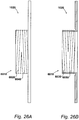
- FIGS. 26A and 26B are respectively a front elevation and a section of the friction ring 1020 with this variant flange 6010.
- a first thread 6020 of one handedness is provided on the outer surface of flange 6010 and a second thread 6030 of opposite handedness is provided on its inner surface. In this embodiment, however, additional threads are provided.
- a third thread 6040 of opposite handedness to first thread 6020 is provided on the outer surface of the flange 6010, and a fourth thread 6050 of opposite handedness to second thread 6030 is provided on the inner surface of the flange 6010.
- FIG. 27 An enlargement of the flange 6010 following casting of a mounting bell 7010 thereon is shown in Figure 27 .
- FIG 27 more contact surface area between the mounting bell 7010 and the threads is provided, but in addition, due to the presence of two threads of opposite handedness on both the inner and outer surfaces of the flange 6010 , there is no tendency for the thread on the outer surface to encourage loosening during braking events, for example.
- Figures 28A and Figure 28B are respectively a section of an alternative embodiment of the friction ring shown in Figure 22 , which has a frustoconical flange 8010, and a section showing the frustoconical flange 8010 encapsulated in a frustoconical mounting bell.
- a first thread 8020 of one handedness is on the outer surface of flange 8010, and a second thread 8030 of opposite handedness is on the inner surface.
- the arrangement of with opposing threads on both the inner and outer surfaces as with flange 6010 could also be used.
- frustoconical form of flange 8010 allows fitment to certain types of vehicle hubs and may be lighter than the cylindrical form of flange 2030.
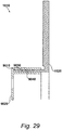
- a further variant flange 9010 comprises threads that are recesses in the flange as shown in Figure 29 .
- the mounting bell 9020 of this variation of the brake disc 1010 fills the inner threads 9030 and the outer threads 9040 on the flange 9010. This may assist in reducing material cost during production as less of the flange needs to be machined away. It will be appreciated by those skilled in the art that this configuration for the threads may be combined with any other variant of the flange.
- Torque transfer between the mounting bell and the friction ring may be improved by the addition of holes in the flange, as shown in the sectional view of Figure 30A .
- the variant flange 9050 includes holes 9060 distributed around its circumference which are filled by the mounting bell 9070.
Landscapes
- Engineering & Computer Science (AREA)
- General Engineering & Computer Science (AREA)
- Mechanical Engineering (AREA)
- Braking Arrangements (AREA)
Abstract
Description
- This invention concerns brake discs, particularly but not necessarily exclusively brake discs for high performance motor vehicles such as sports cars.
- A brake disc of a vehicle comprises a rotor comprising a friction ring that rotates with a ground-engaging wheel of the vehicle and is gripped by caliper-operated pads to slow the vehicle down when required. The friction ring must be able to resist both wear from the brake pads and heat generated by the braking. For these reasons brake disc rotors are conventionally made of cast iron.
- However, as is well known, cast iron is a relatively heavy material for use in a sports car: it is, for instance, about two and a half times as heavy as aluminium. Therefore, to reduce the weight of the disc brake as a whole, the friction ring may be carried on a hub formed of lighter material such as aluminium or an aluminium alloy. The hub, sometimes known as a mounting bell or a "top hat", is in use connected to a ground-engaging wheel or an axle of the wheel.
- This so-called "composite" form of construction (which should not be confused with the possible use of fibre-reinforced plastics materials) contrasts with monolithic forms in which the friction ring and the hub are integrally formed from the same material in that it requires a connection between the hub and the friction ring that will withstand both rotational forces in braking (and acceleration) and transverse forces in cornering.
- Various kinds of such connection have been previously proposed. For example, a friction ring of cast iron may be connected to a substantially lighter cast light-aluminium or deep-drawn sheet-steel brake-disc hub. Spigots on the friction ring engage in associated recesses in the hub to transmit rotational forces and a retaining ring secures the joint against transverse (axial) forces, but additional screw connections are also recommended. However, the retaining ring and screw connections necessarily add to the complexity of such an arrangement, and a simpler arrangement is to be preferred.
- European patent application
EP1426644 describes a composite brake disc in which a rotor comprising grey cast iron has cast onto it a hub section comprising aluminium with a geometric coupling called a "form-fit" connection (formschlüssige Verbindung) between them to deal with the rotational and transverse forces in use. This form-fit connection comprises circumferentially spaced axially-extending teeth on the rotor that are received in axial seats in the hub section and circumferentially spaced radially-extending teeth on the rotor that are received in radial seats in the hub section. - European patent application
EP3081826 describes a composite brake disc in which a rotor comprising grey cast iron has cast onto it a hub comprising aluminium with a connection between the rotor and the hub that comprises circumferentially spaced axial teeth (but not radial teeth) and in which the hub is a shrink-fit on the rotor. This is a simpler and therefore cheaper arrangement than that ofEP1426644 and it also has the advantage of preventing even small relative movements between the rotor and the hub which are admitted inEP1426644 and are undesirable. - The present invention provides improvements over
EP3081826 . - Thus according to a first aspect of the invention there is provided a brake disc for a vehicle, which brake disc comprises:
- a rotor formed of a first material and comprising a friction ring annular about an axis of rotation and, coaxial with the friction ring, a tubular flange extending axially from the friction ring to a free end and having a wall with a radially inner face and a radially outer face; and
- a hub securable to a wheel or an axle of the vehicle for rotation therewith about said axis and being formed of a second material of a lower density, a lower melting point and a higher coefficient of thermal expansion than said first material;
- the hub being cast over said flange to encapsulate at least a portion of said wall and being a shrink fit thereupon;
- characterised in that the encapsulated portion of the wall is so configured and arranged as to permit differential thermal contraction, in an axial direction, of the hub relative to the flange as the hub solidifies and cools after its casting.
- An important benefit of configuring and arranging the encapsulated portion of the wall so as to permit differential thermal expansion of the hub relative to the flange as the hub solidifies and cool after its casting (which will be discussed in more detail hereinafter) is that it minimises retained stresses in the hub. This can be achieved even though, as is preferred, the hub is a shrink-fit on the flange.
- The encapsulated portion of the wall may be formed with axially-extending (but not radially-extending) teeth and it may be made smooth, eg by a machining operation such as turning or honing. In this way the present invention contrasts with the arrangement of
EP1426644 , which has radially-extending teeth and in which the coupling portion of the rotor is explicitly maintained rough, both of which features would act against the differential thermal contraction in the axial direction provided by the present invention. - The flange may have a radial dimension which varies along its axial extent. Otherwise, or as well, the encapsulated portion of the wall may be formed with a screw thread extending helically about the axis of rotation (to allow differential thermal contraction of the hub along the helical path of the thread).
- In a second aspect the invention provides a brake disc for a motor vehicle comprising:
- a friction ring having an inner radius and an outer radius;
- a hollow flange extending axially from the inner radius of the friction ring, and having an inner surface with a first thread thereon, and an outer surface with a second thread thereon of opposite handedness to the first thread; and
- a mounting bell that extends over the inner surface and the outer surface of the flange in engagement with the first thread and the second thread;
- wherein the friction ring and the flange are integrally formed of a first material, and the mounting bell is formed of a second material different to the first material.
- The threads prevent axial separation of the mounting bell and the flange, and the use of threads of opposite handedness facilitates torque transmission in forward and reverse directions of rotation without risk of the mounting bell unscrewing.
- According to a third aspect of the invention there is provided a method of manufacturing a according to the first aspect of the invention, which method comprises the steps of:
- casting the rotor;
- providing a mould with a cavity to receive the rotor and define the form of the hub;
- placing the rotor in said cavity; and
- delivering said second material in a molten state into the mould to encapsulate said portion of the wall of the flange, to solidify thereon and to cool;
- characterised in that said method comprises configuring said portion of the wall of the flange to permit differential thermal contraction, in an axial direction, of the hub relative to the flange as the hub solidifies and cools.
- The invention will now be described by way of example only with reference to the accompanying drawings which are purely schematic and in which -
-
Figures 1 to 4 illustrate a prior art brake disc having a hub cast on to a flange of a rotor to encapsulate a portion of the wall of the flange, which figures comprise respectively inFigure 1 a side elevation, inFigure 2 an end elevation, inFigure 3 a cross section at X-X ofFigure 1 and inFigure 4 a view of circumferentially spaced axially-extending teeth; -
Figures 5 to 8 illustrate a first improvement upon the brake disc ofFigures 1 to 4 , in which the encapsulated portion of the flange wall is smooth, which figures comprise respectively inFigure 5 a side elevation, inFigure 6 an end elevation, inFigure 7 a cross section at X-X ofFigure 5 and inFigure 8 a view of circumferentially spaced axially-extending teeth; -
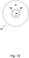
Figures 9 to 11 illustrate a second improvement upon the brake disc ofFigures 1 to 4 , in which the flange has a radial dimension which varies along its axial extent, which figures comprise respectively inFigure 9 a side elevation, inFigure 10 an end elevation and inFigure 11 a cross section at X-X ofFigure 9 , showing the rotor with the hub omitted; -
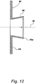
Figures 12 and13 illustrate variants of the varying radial dimension of the flange, in each case showing the rotor in vertical cross section (as inFigures 5 and9 ) with the hub omitted. -
Figures 14 to 16 illustrate a third improvement upon the brake disc ofFigures 1 to 4 , in which the encapsulated portion of the flange wall is formed with a screw thread extending helically about the axis of rotation, which figures comprise respectively inFigure 14 a side elevation, inFigure 15 an end elevation and inFigure 16 a cross section at X-X ofFigure 14 , showing the rotor with the hub omitted; -
Figures 17 to 20 illustrate variants of the screw thread feature, in each case showing the rotor in vertical cross section (as inFigures 5 ,9 ,12 ,13 and16 ) with the hub omitted; -
Figure 21 shows a particular form of brake disc according to the present invention; -
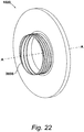
Figure 22 shows the friction ring and the hollow flange of the brake disc shown inFigure 21 ; -
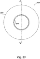
Figure 23 is a plan view of the friction ring shown inFigure 22 ; -
Figure 24A and Figure 24B are respectively a front elevation of the friction ring shown inFigure 22 , and a section along B-B ofFigure 22 ; -
Figure 25 is a section of the brake disc shown inFigure 21 , showing the encapsulation of the flange in the mounting bell; -
Figure 26A and Figure 26B are respectively a front elevation and a section of an alternative embodiment of the friction ring shown inFigure 22 which has two threads of opposite handedness on both the inside and outside of its flange; -
Figure 27 is a section of a brake disc with the friction ring ofFigure 26A and 26B showing the encapsulation of the threads; -
Figure 28A and Figure 28B are respectively a section of an alternative embodiment of the friction ring shown inFigure 22 , which has a frustoconical flange, and a section showing the frustoconical flange encapsulated in a frustoconical mounting bell; -
Figure 29 shows another alternative friction ring with threads that are recessed into the flange; and -
Figure 30A and Figure 30B are respectively a section of another alternative friction ring, having a flange with holes therein and axial castellations, and a section along C-C ofFigure 30A . - Referring first to
Figures 1 to 4 these illustrate a prior art brake disc as described and claimed inEP3081826 (upon which the present invention makes various improvements). - The prior art brake disc of
Figures 1 to 4 comprises a rotor indicated at 10 and a hub indicated generally at 12. Therotor 10 comprises afriction ring 14 annular about an axis 16, being the axis of rotation of a road wheel or axle, not shown. (It should be understood that thefriction ring 14 is shown as a simple annular disc in all the drawings, for simplicity of illustration, but it may well comprise two parallel and coaxial friction elements with an air gap between them for cooling purposes). Atubular flange 18 extends axially from thefriction ring 14 to afree end 18a (Figure 3 ). Thefriction ring 14 extends radially from aninner radius 10a to anouter radius 10b, the inner radius being coterminous with the inside of the hollowcylindrical flange 18. Thefriction ring 14 and theflange 18 are integrally formed from grey cast iron by casting and machining. Thehub 12 is formed by casting from aluminium (or aluminium alloy) and as can be seen most clearly fromFigure 3 the casting extends axially over part of the radially inner and the radially outer faces of theflange 18. That is to say, the casting of thehub 12 encapsulates a portion of theflange 18 and engages radially inner and outer surfaces of theflange 18 and thereby makes a connection between thehub 12 and therotor 10. Thehub 12 is a shrink fit upon the encapsulated portion of theflange 18. In addition, as can be seen fromFigure 4 , theflange 18 is formed with circumferentially spaced axially-extendingteeth 18b encapsulated in the casting of thehub 12. (For simplicity of illustration, only afew teeth 18a are shown inFigure 4 , and in practice there may be more). - Turning now to
Figures 5 to 8 , these illustrate a form of brake disc embodying the present invention. The brake disc ofFigures 5 to 8 comprises a rotor indicated at 20 and a hub indicated generally at 22. Therotor 20 comprises afriction ring 24 annular about anaxis 26, being the axis of rotation of a road wheel or axle, not shown. Atubular flange 28 extends axially from thefriction ring 24 to afree end 28a (Figure 3 ). Thefriction ring 24 and theflange 28 are integrally formed from grey cast iron by casting and machining. Thehub 22 is formed by casting from aluminium (or aluminium alloy) and as can be seen most clearly fromFigure 3 the casting extends axially over part of the radiallyinner face 28c and the radiallyouter face 28d of theflange 28 radially bounding thewall 28e of theflange 28. That is to say, the casting of thehub 12 encapsulates a portion of theflange wall 28e and by engaging the radiallyinner face 28c and the radiallyouter face 28d of theflange 18 makes a connection between thehub 22 and therotor 20. Thehub 22 is a shrink fit upon the encapsulated portion of thewall 28e. In addition, as can be seen fromFigure 8 , theflange 28 is formed at its free end with circumferentially spaced axially-extending teeth 28b encapsulated in the casting of thehub 22. - When aluminium or aluminium alloy (eg of the hub 22) is cast on to grey cast iron (eg of the rotor 20) the interface is liable to a form of galvanic corrosion because of the difference in electrode potential between the two materials. (The same is true, of course, of any two materials of differing electrode potential that are in contact in an electrolyte). Inasmuch as aluminium alloy has a substantially higher coefficient of linear thermal expansion than grey cast iron, the
hub 22 contracts inwardly - towards the axis 26 - rather more than theflange 28 as it cools after being cast, to form a tighter joint with theflange 28. This protects the interface between the two materials against the ingress of moisture which could function as an electrolyte and thereby give rise to galvanic corrosion. - As thus far described, the brake disc of
Figures 5 to 8 is essentially the same as the prior art brake disc ofFigures 1 to 4 . But there is an important underlying difference. This is that the inner andouter surfaces flange wall 28e are both made smooth. This is done by turning or honing etc during the machining of the rotor and its effect is to minimise retained stresses in thehub 22, as will now be explained. Thehub 22 contracts as it solidifies after casting, and carries on contracting relative to therotor 20 as it cools after casting, the aluminium of thehub 22 having a substantially greater coefficient of thermal expansion than the grey cast iron of therotor 20. Thesmooth surfaces hub 22 to retract along thewall 28e of theflange 28, whereby retained stresses in thehub 22 are minimised. The geometry of the interface between thehub 22 and thewall 28e is such that thehub 22 can contract as it cools without geometric resistance imposed by therotor 20 and without weakening of the interface as thehub 22 cools and contacts. Theiron rotor 20 is preheated before thealuminium hub 22 is cast upon it, so it also contracts during the cooling process, but to a lesser degree than thehub 22. - Thus the
smooth faces flange wall 28e permit differential thermal contraction, in an axial direction, of thehub 22 relative to theflange 28, and the result is a strong shrink-fit connection between thehub 22 and therotor 20 without untoward retained stresses in thehub 22. - The encapsulated teeth 28b at the
free end 28a of theflange 28 positively resist rotational forces in use of the brake disc ofFigure 5 to 8 . (The term "positively resist" and related terms used herein should be understood to mean that there is a physical barrier to movement in the direction of the forces applied, and not just a gripping resistance from the shrink-fit connection). It is advisable to provide similarly positive resistance to axial forces. This can be achieved in the present invention without comprising the need to avoid an untoward build-up of retained stresses in the hub, as will now be described firstly with reference toFigures 9 to 11 . - Referring then to
Figures 9 to 11 , abrake disc rotor 30 comprises afriction ring 34 annular about anaxis 36, being the axis of rotation of a road wheel or axle, not shown. Atubular flange 38 extends axially from thefriction ring 34 to afree end 38a. Thefriction ring 34 and theflange 38 are integrally formed from grey cast iron by casting and machining. The radiallyinner face 38c and the radiallyouter surface 38d that bound the wall 38e are both made smooth, as in the arrangement ofFigures 5 to 8 . In addition, however, the radial thickness t of the wall 38e increases towards thefree end 38a of theflange 38. Thus, when an aluminium hub (not shown inFigures 9 to 11 ) cast over theflange 38 solidifies thereon, the configuration of thewall 38 provides positive resistance to axial forces. But the smoothness of the hub-engagingsurfaces flange 38 as the hub solidifies and cools after casting. Thus the arrangement ofFigures 9 to 11 provides positive resistance to axial forces without compromising the need to avoid an untoward build-up of retained stresses in the hub. - As shown in
Figures 9 to 11 , the variation in the radial thickness t of the flange wall 38e is provided by sloping theinner face 38c radially inwardly towards thefree end 38a of theflange 38. However it should be understood that otherwise theouter face 38d may be sloped radially outwardly towards thefree end 38a instead of or as well as having theinner face 38c sloping radially inwardly towards thefree end 38a. -
Figures 12 and13 illustrate other ways in which variation in a radial dimension of the flange along its axial extent can be arranged to provide positive resistance to axial forces. - In the arrangement of
Figure 12 abrake disc rotor 40 comprises afriction ring 44 annular about anaxis 46, being the axis of rotation of a road wheel or axle, not shown. Atubular flange 48 extends axially from thefriction ring 44 to afree end 48a and thefriction ring 44 and theflange 48 are integrally formed from grey cast iron by casting and machining. The radially inner face 48c and the radially outer surface 48d that bound the wall 48e of theflange 48 are both made smooth, as in the arrangement ofFigures 9 to 11 . But in the arrangement ofFigure 12 , instead of varying the thickness of the flange wall as in the arrangement ofFigures 9 to 11 , the diameter d of theflange 48 increases towards itsfree end 48a. This increasing diameter (which may be combined with increasing wall thickness) provides positive resistance to axial forces on the hub (not shown inFigure 12 ) without compromising the need to avoid an untoward build-up of retained stresses in the hub. - In the arrangement of
Figure 13 abrake disc rotor 50 comprises afriction ring 54 annular about anaxis 56, being the axis of rotation of a road wheel or axle, not shown. Atubular flange 58 extends axially from thefriction ring 54 to a free end 58a and thefriction ring 54 and theflange 58 are integrally formed from grey cast iron by casting and machining. The radially inner face 58c and the radially outer surface 58d that bound the wall 58e of theflange 58 are both made smooth, as in the arrangement ofFigure 12 . But in the arrangement ofFigure 13 , the diameter d of theflange 58 decreases towards its free end 58a rather than increasing. This increasing diameter (which may be combined with increasing wall thickness) provides positive resistance to axial forces on the hub (not shown inFigure 13 ) without compromising the need to avoid an untoward build-up of retained stresses in the hub. - Another approach to providing similarly positive resistance to axial forces without comprising the need to avoid an untoward build-up of retained stresses in the hub will now be described with reference to
Figures 14 to 16 . - Referring then to
Figures 14 to 16 , abrake disc rotor 60 comprises afriction ring 64 annular about anaxis 36, being the axis of rotation of a road wheel or axle, not shown. Atubular flange 68 extends axially from thefriction ring 64 to afree end 68a. Thefriction ring 64 and theflange 68 are integrally formed from grey cast iron by casting and machining. Rather than simply being made smooth as in the arrangement ofFigures 5 to 8 , however, in the arrangement ofFigures 14 to 17 the radiallyinner face 68c and the radiallyouter surface 68d of theflange 68 are respectively formed withscrew threads - The hub (not shown) is cast over the
screw threads flange 68 as the hub solidifies and cools after casting. But when the cast hub has solidified and cooled, the screw threads prevent its being pulled axially off the flange. Thus the arrangement ofFigures 14 to 16 provides positive resistance to axial separation of the hub relative to the flange without compromising the need to avoid an untoward build-up of retained stresses in the hub. - In many cases, a single screw thread on the radially
inner face 68c or the radiallyouter face 68d will be sufficient to provide a positive resistance to axial movement of the hub relative to the friction ring. Otherwise, where abnormally high axially forces are expected, eg on a race track, the positive resistance of the two screw threads can be increased by forming them with mutually opposite hands - with theinner screw thread 68c having a righthand thread and theouter screw thread 68d having a left-hand thread, or vice versa. - The screw thread form used in the invention is a stub Acme thread. A trapezoidal form like the Acme thread is used because it is relatively easy to cut (compared with say a square thread) and relatively strong, having a wide base. This applies more so to the stub Acme form, inasmuch as this has a lower depth. And known problems in disassembling the stub Acme thread are not relevant in this use.
- Other thread arrangements that may be used in the present invention will now be described very briefly with reference to
Figures 17 to 20 . - In the arrangement illustrated by
Figure 17 , therotor 70 has aspiral screw thread 72 formed on the free end of the axially-extending tubular flange 74. Thescrew thread 72 functions like the axially extending teeth 28b of the arrangement illustrated byFigures 5 to 8 in that it is encapsulated by the hub (not shown inFigure 16 ) when the hub is cast onto therotor 70 to be a shrink fit thereon. - In the arrangement illustrated by
Figure 18 , therotor 80 has atubular flange 82 extending axially from it that has a diameter that reduces towards itsfree end 82a.Helical screw threads 84 and 86 are formed on the inner and outer faces of theflange 82. When the hub (not shown inFigure 17 ) is cast onto theflange 82 it encapsulated thescrew threads 84 and 86 and forms a secure shrink-fit connection with them. - In the arrangement illustrated by
Figure 19 therotor 90 includes anaxially extending flange 92 with a wall of greater radial thickness than the flanges illustrated by the other drawings hereof. The greater radial thickness accommodates anannular channel 94 withhelical screw threads Figure 19 ) is cast onto theflange 92 it encapsulated thescrew threads - In the arrangement illustrated by
Figure 20 therotor 100 includes an axially-extendingtubular flange 102. Ahelical screw thread 104 is formed on the radially outer surface of theflange 102 and aspiral screw thread 106 is formed on the face of therotor 100 directed in the same direction as theflange 102. When the hub (not shown inFigure 20 ) is cast onto theflange 102 it encapsulates thescrew threads - Brake discs according to the invention are made as follows.
- (a) The rotor, including the axially-extending tubular flange, is cast from grey cast iron on a DISAmatic® production line utilising flaskless, vertically-parted moulds and sacrificial cores. (DISAmatic is a registered trade mark of DISA Industries AS of Taastrup, Denmark).
- (b) A mould is formed with a cavity to receive the rotor and define the form of the hub to be cast thereon.
- (c) A portion of the wall of the rotor is configured to permit differential thermal movement, in an axial direction, between the flange and the hub when the hub is cast thereon.
- (d) The rotor is pre-heated and placed in the cavity of the mould with its flange extending into the hub-defining part of the mould cavity.
- (e) Aluminium alloy in a molten state is delivered into the hub-defining part of the mould cavity to encapsulate a portion of the wall of the flange.
- (f) The rotor and the hub are allowed to cool so that the hub solidifies and shrinks onto the encapsulated portion of the flange.
- If the encapsulated portion of the flange is to be smooth to permit the differential thermal movement, the smoothing is done by machining such as turning, honing or the like.
- If the encapsulated portion of the flange is to have a radial dimension which varies along its axial extent, this is done partly in the casting of the rotor and partly by subsequent machining.
- If the encapsulated portion of the flange is to be formed with a screw thread, this is done by machining after the rotor is cast.
- In more detail, the recommended process for producing a brake disc embodying the present invention is as follows. The cast iron rotor is part machined via computer numerical control (CNC) turning. This creates a cast iron part with axially extending teeth that project, with tapered geometry away from the disc rotor. This cast iron disc rotor has its axially extending teeth and neighbouring rotor area, heated via gas flame to a temperature below the melting point of aluminium, which provides a good bond between the cast aluminium and the iron of the rotor. The heated rotor is placed into a two-piece steel mould and centralised upon a locating feature to ensure concentricity with the aluminium hub mould and the part machined rotor. The mould parts are also heated. The molten aluminium is top-poured and gravity fed into the cavity.
- A particular form of
brake disc 1010 according to the present invention is illustrated inFigure 21 . - In this embodiment, the
brake disc 1010 is a solid disc brake for fitting to a passenger vehicle, but it will be appreciated by those skilled in the art that the principles of the present invention may be extended to ventilated disc brakes targeted at high performance applications. - The
brake disc 1010 has afriction ring 1020 annular around an axis A-A (the axis of rotation of a road wheel or axle, not shown), and a mountingbell 1030. Thefriction ring 1020 is formed of a first material, and the mountingbell 1030 is formed of a second material that is different to the first material. In the present embodiment, thefriction ring 1020 is made of iron, and the mountingbell 1030 is made of aluminium alloy. Other alloys could be used depending upon the application, in particular high carbon content steel may be used for thefriction ring 1020. - As described previously, the present invention is directed towards a composite brake disc and thus provision is made for connection of the mounting
bell 1030 to thefriction ring 1020, the latter of which shown in isolation in a perspective view inFigure 22 and in plan view inFigure 23 . - The
friction ring 1020, which extends radially in a plane from aninner radius 2010 to anouter radius 2020, has ahollow flange 2030 which extends axially from thefriction ring 1020, i.e. orthogonally from its plane. Theinner radius 2010 of thefriction ring 2020 is coterminous with the inside surface of theflange 2030. In the embodiment shown inFigures 22 and23 , theflange 2030 is cylindrical, but other forms are contemplated such as a conical frustum, as will be described with reference toFigures 28A and 28B . - A front elevation of the
friction ring 1020 is shown inFigure 24A , and a section along B-B ofFigure 23 , is shown inFigure 24 . - Referring to
Figure 24A , the outer surface of theflange 2030 has afirst thread 4010 thereon. Referring toFigure 24B , the inner surface of theflange 2030 has asecond thread 4020 thereon. In the present example,first thread 4010 is a left-handed thread and thesecond thread 4020 is a right-handed thread: they are therefore of opposite handedness. It will of course be appreciate that the handedness of the first and second threads may be reversed. - In practice, the
brake disc 1010 of the present invention is manufactured by first pre-forming thefriction ring 1020. In the present embodiment, this is achieved in an embodiment by casting thefriction ring 1020 from the chosen first material, and then subjecting it to appropriate machining to form the threads on theflange 2030. - The
friction ring 1020 is then located in a mould having a cavity for theflange 2030. The cavity has the desired shape for the mountingbell 1030. Molten second material is delivered into the cavity to fill and engage with the flange. The mountingbell 1030 is then allowed to cool and solidify in the mould. Optionally, thefriction ring 1020 may be heated prior to delivery of the second material to improve the interface between the materials, and reduce any thermal shock caused by the addition of molten second material. - Those skilled in the art will appreciate that after the mounting
bell 1030 has been cast on to theflange 2030, thebrake disc 1010 comprising thefriction ring 1020 plus mountingbell 1030 can be subject as a whole to further machining before it is fitted to a vehicle. In addition, alternative methods of attaching the mounting bell to the flange are contemplated, such as the forming of the mounting bell as a multi-part component to be fitted around the pre-formed flange on the friction ring for joining thereto. - In a specific embodiment, the second material for the mounting
bell 1030 is selected so that has a higher coefficient of linear thermal expansion than the first material of thefriction ring 1020. For example, as described previously iron or an alloy thereof (such as grey iron) may be used for the friction ring and aluminium or an alloy thereof for the hub. During manufacture, the mountingbell 1030 contracts more than theflange 2030 as it cools after being cast. This, in combination with the mountingbell 1030 being arranged to extend over both the outer and inner surfaces of theflange 2030, results in a tighter joint being formed. - Not only does this result in a stronger joint that can be subjected to greater axial forces, it also results in an interface between the first material and second material that is better protected against the ingress of moisture which could function as an electrolyte and thereby give rise to galvanic corrosion. As will be appreciated by those skilled in the art, the interface between two materials of differing electrode potential is liable to galvanic corrosion in the presence of an electrolyte, such as is the case when, for example, an aluminium alloy is cast on to grey cast iron.
-
Figure 25 therefore shows an enlargement of the section of thefriction ring 1020 shown inFigure 24B following casting of the mountingbell 1030 thereon. - As can be seen, the
first thread 4010 and thesecond thread 4020 are encapsulated in the mountingbell 1030. Thus any torque applied that may tend to result in a loosening with respect to one thread results in a tightening with respect to the other. Torque transmission in forward and reverse directions of rotation is therefore permitted without risk of the mounting bell separating from the flange. - Various modifications of the
brake disc 1010 are possible, and one of these is the provision of additional threads on theflange 2030. Such an embodiment is illustrated inFigures 26A and 26B , which are respectively a front elevation and a section of thefriction ring 1020 with thisvariant flange 6010. - As with
flange 2030, afirst thread 6020 of one handedness is provided on the outer surface offlange 6010 and asecond thread 6030 of opposite handedness is provided on its inner surface. In this embodiment, however, additional threads are provided. Thus, athird thread 6040 of opposite handedness tofirst thread 6020 is provided on the outer surface of theflange 6010, and afourth thread 6050 of opposite handedness tosecond thread 6030 is provided on the inner surface of theflange 6010. - An enlargement of the
flange 6010 following casting of a mountingbell 7010 thereon is shown inFigure 27 . As can be seen inFigure 27 , more contact surface area between the mountingbell 7010 and the threads is provided, but in addition, due to the presence of two threads of opposite handedness on both the inner and outer surfaces of theflange 6010, there is no tendency for the thread on the outer surface to encourage loosening during braking events, for example. - Another modification of the
brake disc 1010 is shown inFigures 28A and Figure 28B , which are respectively a section of an alternative embodiment of the friction ring shown inFigure 22 , which has afrustoconical flange 8010, and a section showing thefrustoconical flange 8010 encapsulated in a frustoconical mounting bell. Afirst thread 8020 of one handedness is on the outer surface offlange 8010, and asecond thread 8030 of opposite handedness is on the inner surface. The arrangement of with opposing threads on both the inner and outer surfaces as withflange 6010 could also be used. - The frustoconical form of
flange 8010 allows fitment to certain types of vehicle hubs and may be lighter than the cylindrical form offlange 2030. - Whilst the threads on
flanges Figure 29 . Thus, the mountingbell 9020 of this variation of thebrake disc 1010 fills the inner threads 9030 and theouter threads 9040 on the flange 9010. This may assist in reducing material cost during production as less of the flange needs to be machined away. It will be appreciated by those skilled in the art that this configuration for the threads may be combined with any other variant of the flange. - Torque transfer between the mounting bell and the friction ring may be improved by the addition of holes in the flange, as shown in the sectional view of
Figure 30A . The variant flange 9050 includes holes 9060 distributed around its circumference which are filled by the mounting bell 9070. - Further improvement in torque transfer can be achieved by inclusion of axial castellations 9080, as shown in
Figure 30B which is a section on C-C ofFigure 30A . - Addition of either (or both) of the holes and castellations can help remove stress on the threads under braking and acceleration.
Claims (15)
- A brake disc for a vehicle, which brake disc comprises:a rotor (20) formed of a first material and comprising a friction ring (24) annular about an axis of rotation (26) and, coaxial with the friction ring (14), a tubular flange (28) extending axially from the friction ring (24) to a free end (28a) and having a wall (28e) with a radially inner face (28c) and a radially outer face (28d); anda hub (22) securable to a wheel or an axle of the vehicle for rotation therewith about said axis (26) and being formed of a second material of a lower density, a lower melting point and a higher coefficient of thermal expansion than said first material;the hub (22) being cast over said flange (28) to encapsulate at least a portion of said wall (28e) and being a shrink fit thereupon;characterised in that the encapsulated portion of the wall (28e) is so configured and arranged as to permit differential thermal contraction, in an axial direction, of the hub (22) relative to the flange (28) as the hub (22) solidifies and cools after its casting.
- A brake disc as claimed in Claim 1 characterised in that the encapsulated portion of the wall (28e) is formed with axially extending teeth (28b) circumferentially spaced apart at the free end (28a) of the flange (28).
- A brake disc as claimed in Claim 1 or Claim 2 characterised in that the encapsulated portion of the wall (28e) is smooth so as to permit said differential thermal contraction of the hub (22).
- A brake disc as claimed in any preceding claim characterised in that the flange (28) has a radial dimension which varies along its axial extent.
- A brake disc as claimed in Claim 4 characterised in that said radial dimension is the thickness (t) of the wall (38e) of the flange (38) and said thickness (t) increases towards the free end (38a) of the flange (38) or reduces towards the free end (38a) of the flange (38).
- A brake disc as claimed in Claim 4 characterised in that said radial dimension is the diameter (d) of the flange (48/58), which increases towards the free end (48a) of the flange (48) or reduces towards the free end (58a) of the flange (58).
- A brake disc as claimed in Claim 1 or Claim 2 characterised in that the encapsulated portion of the wall of the tubular flange (68) is formed with a screw thread extending helically about the axis (36) of rotation.
- A brake disc as claimed in Claim 7 characterised in that the encapsulated portion of the wall is formed with a first said screw thread (68f) on the radially inner face (68c) of the wall and a second said screw thread (68f) on the radially outer face (68d) of the wall.
- A brake disc as claimed in Claim 8 characterised in that the first screw thread (68f) and the second screw thread (68g) are of mutually opposite hands.
- A brake disc as claimed in any preceding claim characterised in that said first material comprises iron from which the friction ring and the flange are integrally formed by casting and said second material comprises aluminium or an alloy thereof.
- A brake disc (1010) for a vehicle, comprising:a friction ring (1020) annular about an axis (A-A) and having an inner radius (2010) and an outer radius (2020);a hollow flange (2030) extending axially from the inner radius (2010) of the friction ring (1020), and having an outer surface with a first thread (4010) thereon, and an inner surface with a second thread (4020) thereon of opposite handedness to the first thread (4010);a mounting bell (1030) that extends over the outer surface and the inner surface of the flange (2030) in engagement with the first thread (4010) and the second thread (4020);characterised in that the friction ring (1020) and the flange (2030) are integrally formed of grey cast iron, and the mounting bell (1030) is formed of aluminium or an alloy thereof.
- A brake disc as claimed in Claim 11 characterised in that the hollow flange (2030) is of cylindrical or frustoconical form.
- A method of manufacturing a brake disc as claimed in Claim 1, which method comprises the steps of:casting the rotor;providing a mould with a cavity to receive the rotor and define the form of the hub;placing the rotor in said cavity; anddelivering said second material in a molten state into the mould to encapsulate said portion of the wall of the flange, to solidify thereon and to cool;characterised in that said method comprises configuring said portion of the wall of the flange to permit differential thermal contraction, in an axial direction, of the hub relative to the flange as the hub solidifies and cools.
- A method of manufacturing a brake disc as claimed in Claim 13 characterised in that said method comprises smoothing at least a section of the portion of the wall to be encapsulated in the hub before placing the rotor in the mould.
- A method of manufacturing a brake disc as claimed in Claim 13 or Claim 14 characterised in that said method comprises heating the rotor before placing it in the mould.
Applications Claiming Priority (2)
| Application Number | Priority Date | Filing Date | Title |
|---|---|---|---|
| GBGB1612891.0A GB201612891D0 (en) | 2016-07-26 | 2016-07-26 | Brake discs |
| GB1706068.2A GB2552568B (en) | 2016-07-26 | 2017-04-13 | Brake discs |
Publications (2)
| Publication Number | Publication Date |
|---|---|
| EP3290735A1 true EP3290735A1 (en) | 2018-03-07 |
| EP3290735B1 EP3290735B1 (en) | 2023-05-17 |
Family
ID=56894394
Family Applications (1)
| Application Number | Title | Priority Date | Filing Date |
|---|---|---|---|
| EP17250006.8A Active EP3290735B1 (en) | 2016-07-26 | 2017-07-25 | Brake discs |
Country Status (4)
| Country | Link |
|---|---|
| US (1) | US10352381B2 (en) |
| EP (1) | EP3290735B1 (en) |
| CN (1) | CN207514123U (en) |
| GB (2) | GB201612891D0 (en) |
Families Citing this family (5)
| Publication number | Priority date | Publication date | Assignee | Title |
|---|---|---|---|---|
| GB201612891D0 (en) * | 2016-07-26 | 2016-09-07 | Eurac Ltd | Brake discs |
| CN108788095B (en) * | 2018-06-20 | 2020-04-28 | 四川共享铸造有限公司 | Casting method of steel pipe with cast-in oil duct |
| CN108999896A (en) * | 2018-10-18 | 2018-12-14 | 徐州工程学院 | A kind of magnetorheological fluid accident brake |
| DE102019134981A1 (en) * | 2019-12-18 | 2021-06-24 | Audi Ag | Brake disc and method of manufacturing a brake disc |
| CN115875386A (en) * | 2021-09-29 | 2023-03-31 | 六和机械股份有限公司 | Brake disc |
Citations (4)
| Publication number | Priority date | Publication date | Assignee | Title |
|---|---|---|---|---|
| JPS58211550A (en) * | 1982-06-03 | 1983-12-09 | Honda Motor Co Ltd | Cylinder block |
| EP1426644A2 (en) * | 2002-11-16 | 2004-06-09 | Bayerische Motoren Werke Aktiengesellschaft | Assembled brake disc for a vehicle disc brake |
| US20090032674A1 (en) * | 2007-08-01 | 2009-02-05 | Gm Global Technology Operations, Inc. | Damped product with insert and method of making the same |
| EP3081826A1 (en) * | 2015-04-15 | 2016-10-19 | Eurac Limited | Brake discs |
Family Cites Families (21)
| Publication number | Priority date | Publication date | Assignee | Title |
|---|---|---|---|---|
| US2603316A (en) * | 1952-07-15 | Brake rotor | ||
| DE19708901A1 (en) * | 1997-03-05 | 1998-09-17 | Knorr Bremse Systeme | Wave brake disc for disc brake systems of rail vehicles |
| DE19719634C1 (en) | 1997-05-09 | 1999-03-04 | Daimler Benz Ag | Brake unit with a ceramic brake disk bolted to a hub |
| FR2764352B1 (en) * | 1997-06-05 | 1999-09-10 | Messier Bugatti | DISC FRICTION ASSEMBLY, ESPECIALLY FOR HEAVYWEIGHT |
| US7226667B2 (en) | 2002-05-13 | 2007-06-05 | Honda Giken Kogyo Kabushiki Kaisha | Cast-iron insert and method of manufacturing same |
| US6994189B2 (en) * | 2003-03-18 | 2006-02-07 | Kun Teng Industry Co., Ltd | Brakable wheel hub device |
| US7775332B2 (en) * | 2005-09-15 | 2010-08-17 | Gm Global Technology Operations, Inc. | Bi-metal disc brake rotor and method of manufacturing |
| US7975750B2 (en) * | 2004-10-08 | 2011-07-12 | GM Global Technology Operations LLC | Coulomb friction damped disc brake rotors |
| US20060081425A1 (en) * | 2004-10-15 | 2006-04-20 | Hubert Chen | Brake disk and a brakable wheel hub device having the same |
| WO2007033378A1 (en) | 2005-09-14 | 2007-03-22 | Benmaxx, Llc | Lightweight reinforced castings and method for making same |
| DE102007039577A1 (en) * | 2007-08-22 | 2009-02-26 | Daimler Ag | Brake disk for motor vehicle e.g. passenger car, has friction ring and wheel flange connected with each other by intermediate component, which exhibits higher elasticity relative to connection area of wheel flange |
| US8210232B2 (en) | 2007-09-20 | 2012-07-03 | GM Global Technology Operations LLC | Lightweight brake rotor and components with composite materials |
| US8006740B2 (en) * | 2008-10-08 | 2011-08-30 | Synergen, Inc | High performance brake rotor |
| IT1403905B1 (en) * | 2011-01-26 | 2013-11-08 | Freni Brembo Spa | DISC FOR DISC BRAKES |
| KR101294165B1 (en) * | 2011-08-10 | 2013-08-08 | 현대자동차주식회사 | Brake disc using different materials and method for producing the same |
| US9776241B2 (en) * | 2012-04-18 | 2017-10-03 | Xiaodi Huang | High thermal conductivity disk brakes |
| KR20150061665A (en) * | 2013-11-18 | 2015-06-05 | 현대자동차주식회사 | Brake Disc Using Different Materials and Method for Manufacturing The Same |
| US9334910B2 (en) * | 2014-05-28 | 2016-05-10 | Shimano Inc. | Lock member for fixedly locking a disc brake rotor on a bicycle hub |
| US9982732B2 (en) * | 2015-08-04 | 2018-05-29 | Gri Engineering & Development, Llc | Vehicle brake rotor and method of making same |
| US20170074336A1 (en) * | 2015-09-16 | 2017-03-16 | Performance Friction Corporation | Disc brake assembly |
| GB201612891D0 (en) * | 2016-07-26 | 2016-09-07 | Eurac Ltd | Brake discs |
-
2016
- 2016-07-26 GB GBGB1612891.0A patent/GB201612891D0/en not_active Ceased
-
2017
- 2017-04-13 GB GB1706068.2A patent/GB2552568B/en active Active
- 2017-07-25 EP EP17250006.8A patent/EP3290735B1/en active Active
- 2017-07-26 US US15/660,043 patent/US10352381B2/en active Active
- 2017-07-26 CN CN201720918899.4U patent/CN207514123U/en active Active
Patent Citations (4)
| Publication number | Priority date | Publication date | Assignee | Title |
|---|---|---|---|---|
| JPS58211550A (en) * | 1982-06-03 | 1983-12-09 | Honda Motor Co Ltd | Cylinder block |
| EP1426644A2 (en) * | 2002-11-16 | 2004-06-09 | Bayerische Motoren Werke Aktiengesellschaft | Assembled brake disc for a vehicle disc brake |
| US20090032674A1 (en) * | 2007-08-01 | 2009-02-05 | Gm Global Technology Operations, Inc. | Damped product with insert and method of making the same |
| EP3081826A1 (en) * | 2015-04-15 | 2016-10-19 | Eurac Limited | Brake discs |
Also Published As
| Publication number | Publication date |
|---|---|
| GB201612891D0 (en) | 2016-09-07 |
| US10352381B2 (en) | 2019-07-16 |
| GB201706068D0 (en) | 2017-05-31 |
| CN207514123U (en) | 2018-06-19 |
| GB2552568B (en) | 2019-03-20 |
| GB2552568A (en) | 2018-01-31 |
| US20180058523A1 (en) | 2018-03-01 |
| EP3290735B1 (en) | 2023-05-17 |
Similar Documents
| Publication | Publication Date | Title |
|---|---|---|
| EP3290735B1 (en) | Brake discs | |
| EP2558737B1 (en) | A flanged bearing ring for a motor vehicle wheel bearing unit | |
| US7861832B2 (en) | Thermally accommodating interconnection for cast-in-place components | |
| US6321885B1 (en) | Composite cast brake elements, such as brake drum, brake disk or the like, and composite casting process for brake elements | |
| US9174274B2 (en) | Low mass multi-piece sound dampened article | |
| US20040084260A1 (en) | Integrated brake rotor | |
| EP2668414B1 (en) | Disc for disc brakes | |
| GB2059298A (en) | Motor vehicle wheel comprising two fixedly interconnected parts | |
| MX2010012118A (en) | Composite brake disc. | |
| EP2378142B1 (en) | A flanged bearing ring for a motor vehicle wheel bearing unit | |
| EP2980436B1 (en) | Disc for disc brakes and process for manufacturing the same | |
| US11187290B2 (en) | Aluminum ceramic composite brake assembly | |
| US20180252282A1 (en) | Vehicle brake rotor and method of making same | |
| EP3081826A1 (en) | Brake discs | |
| CN102308107A (en) | Method for installing a double bearing in a casting, wheel comprising a double bearing, and joint with double bearing | |
| CN106605078A (en) | Disc brake with energizing ring | |
| WO1997040285A1 (en) | Integrated brake rotor and wheel hub | |
| US20260103024A1 (en) | Knuckle assembly | |
| CN220268275U (en) | Riveted aluminum brake discs | |
| EP3825143B1 (en) | Vehicle wheel manufactured by high energy beam welding | |
| US6463660B1 (en) | Process for forming a vehicle wheel disc directly upon a vehicle wheel rim | |
| CN111379801B (en) | Aluminum ceramic composite material brake component | |
| KR101766079B1 (en) | Manufacturing method of brake disc | |
| JP6620444B2 (en) | Method of manufacturing bearing ring and vehicle bearing | |
| WO2023074659A1 (en) | Bonding joint for bonding to resin, bonding joint manufacturing method, and metal-resin bonding structure |
Legal Events
| Date | Code | Title | Description |
|---|---|---|---|
| PUAI | Public reference made under article 153(3) epc to a published international application that has entered the european phase |
Free format text: ORIGINAL CODE: 0009012 |
|
| STAA | Information on the status of an ep patent application or granted ep patent |
Free format text: STATUS: THE APPLICATION HAS BEEN PUBLISHED |
|
| AK | Designated contracting states |
Kind code of ref document: A1 Designated state(s): AL AT BE BG CH CY CZ DE DK EE ES FI FR GB GR HR HU IE IS IT LI LT LU LV MC MK MT NL NO PL PT RO RS SE SI SK SM TR |
|
| AX | Request for extension of the european patent |
Extension state: BA ME |
|
| STAA | Information on the status of an ep patent application or granted ep patent |
Free format text: STATUS: REQUEST FOR EXAMINATION WAS MADE |
|
| 17P | Request for examination filed |
Effective date: 20180405 |
|
| RBV | Designated contracting states (corrected) |
Designated state(s): AL AT BE BG CH CY CZ DE DK EE ES FI FR GB GR HR HU IE IS IT LI LT LU LV MC MK MT NL NO PL PT RO RS SE SI SK SM TR |
|
| STAA | Information on the status of an ep patent application or granted ep patent |
Free format text: STATUS: EXAMINATION IS IN PROGRESS |
|
| 17Q | First examination report despatched |
Effective date: 20190816 |
|
| GRAP | Despatch of communication of intention to grant a patent |
Free format text: ORIGINAL CODE: EPIDOSNIGR1 |
|
| STAA | Information on the status of an ep patent application or granted ep patent |
Free format text: STATUS: GRANT OF PATENT IS INTENDED |
|
| INTG | Intention to grant announced |
Effective date: 20230126 |
|
| GRAS | Grant fee paid |
Free format text: ORIGINAL CODE: EPIDOSNIGR3 |
|
| GRAA | (expected) grant |
Free format text: ORIGINAL CODE: 0009210 |
|
| STAA | Information on the status of an ep patent application or granted ep patent |
Free format text: STATUS: THE PATENT HAS BEEN GRANTED |
|
| AK | Designated contracting states |
Kind code of ref document: B1 Designated state(s): AL AT BE BG CH CY CZ DE DK EE ES FI FR GB GR HR HU IE IS IT LI LT LU LV MC MK MT NL NO PL PT RO RS SE SI SK SM TR |
|
| REG | Reference to a national code |
Ref country code: GB Ref legal event code: FG4D |
|
| REG | Reference to a national code |
Ref country code: CH Ref legal event code: EP |
|
| REG | Reference to a national code |
Ref country code: DE Ref legal event code: R096 Ref document number: 602017068832 Country of ref document: DE |
|
| REG | Reference to a national code |
Ref country code: IE Ref legal event code: FG4D |
|
| P01 | Opt-out of the competence of the unified patent court (upc) registered |
Effective date: 20230321 |
|
| REG | Reference to a national code |
Ref country code: AT Ref legal event code: REF Ref document number: 1568485 Country of ref document: AT Kind code of ref document: T Effective date: 20230615 |
|
| REG | Reference to a national code |
Ref country code: LT Ref legal event code: MG9D |
|
| REG | Reference to a national code |
Ref country code: NL Ref legal event code: MP Effective date: 20230517 |
|
| REG | Reference to a national code |
Ref country code: AT Ref legal event code: MK05 Ref document number: 1568485 Country of ref document: AT Kind code of ref document: T Effective date: 20230517 |
|
| PG25 | Lapsed in a contracting state [announced via postgrant information from national office to epo] |
Ref country code: SE Free format text: LAPSE BECAUSE OF FAILURE TO SUBMIT A TRANSLATION OF THE DESCRIPTION OR TO PAY THE FEE WITHIN THE PRESCRIBED TIME-LIMIT Effective date: 20230517 Ref country code: PT Free format text: LAPSE BECAUSE OF FAILURE TO SUBMIT A TRANSLATION OF THE DESCRIPTION OR TO PAY THE FEE WITHIN THE PRESCRIBED TIME-LIMIT Effective date: 20230918 Ref country code: NO Free format text: LAPSE BECAUSE OF FAILURE TO SUBMIT A TRANSLATION OF THE DESCRIPTION OR TO PAY THE FEE WITHIN THE PRESCRIBED TIME-LIMIT Effective date: 20230817 Ref country code: NL Free format text: LAPSE BECAUSE OF FAILURE TO SUBMIT A TRANSLATION OF THE DESCRIPTION OR TO PAY THE FEE WITHIN THE PRESCRIBED TIME-LIMIT Effective date: 20230517 Ref country code: ES Free format text: LAPSE BECAUSE OF FAILURE TO SUBMIT A TRANSLATION OF THE DESCRIPTION OR TO PAY THE FEE WITHIN THE PRESCRIBED TIME-LIMIT Effective date: 20230517 Ref country code: AT Free format text: LAPSE BECAUSE OF FAILURE TO SUBMIT A TRANSLATION OF THE DESCRIPTION OR TO PAY THE FEE WITHIN THE PRESCRIBED TIME-LIMIT Effective date: 20230517 |
|
| PG25 | Lapsed in a contracting state [announced via postgrant information from national office to epo] |
Ref country code: RS Free format text: LAPSE BECAUSE OF FAILURE TO SUBMIT A TRANSLATION OF THE DESCRIPTION OR TO PAY THE FEE WITHIN THE PRESCRIBED TIME-LIMIT Effective date: 20230517 Ref country code: PL Free format text: LAPSE BECAUSE OF FAILURE TO SUBMIT A TRANSLATION OF THE DESCRIPTION OR TO PAY THE FEE WITHIN THE PRESCRIBED TIME-LIMIT Effective date: 20230517 Ref country code: LV Free format text: LAPSE BECAUSE OF FAILURE TO SUBMIT A TRANSLATION OF THE DESCRIPTION OR TO PAY THE FEE WITHIN THE PRESCRIBED TIME-LIMIT Effective date: 20230517 Ref country code: LT Free format text: LAPSE BECAUSE OF FAILURE TO SUBMIT A TRANSLATION OF THE DESCRIPTION OR TO PAY THE FEE WITHIN THE PRESCRIBED TIME-LIMIT Effective date: 20230517 Ref country code: IS Free format text: LAPSE BECAUSE OF FAILURE TO SUBMIT A TRANSLATION OF THE DESCRIPTION OR TO PAY THE FEE WITHIN THE PRESCRIBED TIME-LIMIT Effective date: 20230917 Ref country code: HR Free format text: LAPSE BECAUSE OF FAILURE TO SUBMIT A TRANSLATION OF THE DESCRIPTION OR TO PAY THE FEE WITHIN THE PRESCRIBED TIME-LIMIT Effective date: 20230517 Ref country code: GR Free format text: LAPSE BECAUSE OF FAILURE TO SUBMIT A TRANSLATION OF THE DESCRIPTION OR TO PAY THE FEE WITHIN THE PRESCRIBED TIME-LIMIT Effective date: 20230818 |
|
| PG25 | Lapsed in a contracting state [announced via postgrant information from national office to epo] |
Ref country code: FI Free format text: LAPSE BECAUSE OF FAILURE TO SUBMIT A TRANSLATION OF THE DESCRIPTION OR TO PAY THE FEE WITHIN THE PRESCRIBED TIME-LIMIT Effective date: 20230517 |
|
| PG25 | Lapsed in a contracting state [announced via postgrant information from national office to epo] |
Ref country code: SK Free format text: LAPSE BECAUSE OF FAILURE TO SUBMIT A TRANSLATION OF THE DESCRIPTION OR TO PAY THE FEE WITHIN THE PRESCRIBED TIME-LIMIT Effective date: 20230517 |
|
| PG25 | Lapsed in a contracting state [announced via postgrant information from national office to epo] |
Ref country code: SM Free format text: LAPSE BECAUSE OF FAILURE TO SUBMIT A TRANSLATION OF THE DESCRIPTION OR TO PAY THE FEE WITHIN THE PRESCRIBED TIME-LIMIT Effective date: 20230517 Ref country code: SK Free format text: LAPSE BECAUSE OF FAILURE TO SUBMIT A TRANSLATION OF THE DESCRIPTION OR TO PAY THE FEE WITHIN THE PRESCRIBED TIME-LIMIT Effective date: 20230517 Ref country code: RO Free format text: LAPSE BECAUSE OF FAILURE TO SUBMIT A TRANSLATION OF THE DESCRIPTION OR TO PAY THE FEE WITHIN THE PRESCRIBED TIME-LIMIT Effective date: 20230517 Ref country code: EE Free format text: LAPSE BECAUSE OF FAILURE TO SUBMIT A TRANSLATION OF THE DESCRIPTION OR TO PAY THE FEE WITHIN THE PRESCRIBED TIME-LIMIT Effective date: 20230517 Ref country code: DK Free format text: LAPSE BECAUSE OF FAILURE TO SUBMIT A TRANSLATION OF THE DESCRIPTION OR TO PAY THE FEE WITHIN THE PRESCRIBED TIME-LIMIT Effective date: 20230517 Ref country code: CZ Free format text: LAPSE BECAUSE OF FAILURE TO SUBMIT A TRANSLATION OF THE DESCRIPTION OR TO PAY THE FEE WITHIN THE PRESCRIBED TIME-LIMIT Effective date: 20230517 |
|
| REG | Reference to a national code |
Ref country code: DE Ref legal event code: R097 Ref document number: 602017068832 Country of ref document: DE |
|
| PG25 | Lapsed in a contracting state [announced via postgrant information from national office to epo] |
Ref country code: MC Free format text: LAPSE BECAUSE OF FAILURE TO SUBMIT A TRANSLATION OF THE DESCRIPTION OR TO PAY THE FEE WITHIN THE PRESCRIBED TIME-LIMIT Effective date: 20230517 |
|
| PG25 | Lapsed in a contracting state [announced via postgrant information from national office to epo] |
Ref country code: MC Free format text: LAPSE BECAUSE OF FAILURE TO SUBMIT A TRANSLATION OF THE DESCRIPTION OR TO PAY THE FEE WITHIN THE PRESCRIBED TIME-LIMIT Effective date: 20230517 |
|
| REG | Reference to a national code |
Ref country code: CH Ref legal event code: PL |
|
| REG | Reference to a national code |
Ref country code: BE Ref legal event code: MM Effective date: 20230731 |
|
| PG25 | Lapsed in a contracting state [announced via postgrant information from national office to epo] |
Ref country code: LU Free format text: LAPSE BECAUSE OF NON-PAYMENT OF DUE FEES Effective date: 20230725 |
|
| PLBE | No opposition filed within time limit |
Free format text: ORIGINAL CODE: 0009261 |
|
| STAA | Information on the status of an ep patent application or granted ep patent |
Free format text: STATUS: NO OPPOSITION FILED WITHIN TIME LIMIT |
|
| PG25 | Lapsed in a contracting state [announced via postgrant information from national office to epo] |
Ref country code: LU Free format text: LAPSE BECAUSE OF NON-PAYMENT OF DUE FEES Effective date: 20230725 |
|
| 26N | No opposition filed |
Effective date: 20240220 |
|
| GBPC | Gb: european patent ceased through non-payment of renewal fee |
Effective date: 20230817 |
|
| REG | Reference to a national code |
Ref country code: IE Ref legal event code: MM4A |
|
| PG25 | Lapsed in a contracting state [announced via postgrant information from national office to epo] |
Ref country code: CH Free format text: LAPSE BECAUSE OF NON-PAYMENT OF DUE FEES Effective date: 20230731 |
|
| PG25 | Lapsed in a contracting state [announced via postgrant information from national office to epo] |
Ref country code: SI Free format text: LAPSE BECAUSE OF FAILURE TO SUBMIT A TRANSLATION OF THE DESCRIPTION OR TO PAY THE FEE WITHIN THE PRESCRIBED TIME-LIMIT Effective date: 20230517 |
|
| PG25 | Lapsed in a contracting state [announced via postgrant information from national office to epo] |
Ref country code: SI Free format text: LAPSE BECAUSE OF FAILURE TO SUBMIT A TRANSLATION OF THE DESCRIPTION OR TO PAY THE FEE WITHIN THE PRESCRIBED TIME-LIMIT Effective date: 20230517 Ref country code: IT Free format text: LAPSE BECAUSE OF FAILURE TO SUBMIT A TRANSLATION OF THE DESCRIPTION OR TO PAY THE FEE WITHIN THE PRESCRIBED TIME-LIMIT Effective date: 20230517 Ref country code: FR Free format text: LAPSE BECAUSE OF NON-PAYMENT OF DUE FEES Effective date: 20230731 Ref country code: BE Free format text: LAPSE BECAUSE OF NON-PAYMENT OF DUE FEES Effective date: 20230731 |
|
| PG25 | Lapsed in a contracting state [announced via postgrant information from national office to epo] |
Ref country code: IE Free format text: LAPSE BECAUSE OF NON-PAYMENT OF DUE FEES Effective date: 20230725 |
|
| PG25 | Lapsed in a contracting state [announced via postgrant information from national office to epo] |
Ref country code: GB Free format text: LAPSE BECAUSE OF NON-PAYMENT OF DUE FEES Effective date: 20230817 |
|
| PG25 | Lapsed in a contracting state [announced via postgrant information from national office to epo] |
Ref country code: IE Free format text: LAPSE BECAUSE OF NON-PAYMENT OF DUE FEES Effective date: 20230725 Ref country code: GB Free format text: LAPSE BECAUSE OF NON-PAYMENT OF DUE FEES Effective date: 20230817 |
|
| PG25 | Lapsed in a contracting state [announced via postgrant information from national office to epo] |
Ref country code: BG Free format text: LAPSE BECAUSE OF FAILURE TO SUBMIT A TRANSLATION OF THE DESCRIPTION OR TO PAY THE FEE WITHIN THE PRESCRIBED TIME-LIMIT Effective date: 20230517 |
|
| PG25 | Lapsed in a contracting state [announced via postgrant information from national office to epo] |
Ref country code: BG Free format text: LAPSE BECAUSE OF FAILURE TO SUBMIT A TRANSLATION OF THE DESCRIPTION OR TO PAY THE FEE WITHIN THE PRESCRIBED TIME-LIMIT Effective date: 20230517 |
|
| PG25 | Lapsed in a contracting state [announced via postgrant information from national office to epo] |
Ref country code: CY Free format text: LAPSE BECAUSE OF FAILURE TO SUBMIT A TRANSLATION OF THE DESCRIPTION OR TO PAY THE FEE WITHIN THE PRESCRIBED TIME-LIMIT; INVALID AB INITIO Effective date: 20170725 |
|
| PG25 | Lapsed in a contracting state [announced via postgrant information from national office to epo] |
Ref country code: HU Free format text: LAPSE BECAUSE OF FAILURE TO SUBMIT A TRANSLATION OF THE DESCRIPTION OR TO PAY THE FEE WITHIN THE PRESCRIBED TIME-LIMIT; INVALID AB INITIO Effective date: 20170725 |
|
| PGFP | Annual fee paid to national office [announced via postgrant information from national office to epo] |
Ref country code: DE Payment date: 20250722 Year of fee payment: 9 |
|
| PG25 | Lapsed in a contracting state [announced via postgrant information from national office to epo] |
Ref country code: TR Free format text: LAPSE BECAUSE OF FAILURE TO SUBMIT A TRANSLATION OF THE DESCRIPTION OR TO PAY THE FEE WITHIN THE PRESCRIBED TIME-LIMIT Effective date: 20230517 |