EP3081826A1 - Brake discs - Google Patents
Brake discs Download PDFInfo
- Publication number
- EP3081826A1 EP3081826A1 EP16250008.6A EP16250008A EP3081826A1 EP 3081826 A1 EP3081826 A1 EP 3081826A1 EP 16250008 A EP16250008 A EP 16250008A EP 3081826 A1 EP3081826 A1 EP 3081826A1
- Authority
- EP
- European Patent Office
- Prior art keywords
- flange
- brake disc
- hub
- brake
- casting
- Prior art date
- Legal status (The legal status is an assumption and is not a legal conclusion. Google has not performed a legal analysis and makes no representation as to the accuracy of the status listed.)
- Withdrawn
Links
Images








Classifications
-
- F—MECHANICAL ENGINEERING; LIGHTING; HEATING; WEAPONS; BLASTING
- F16—ENGINEERING ELEMENTS AND UNITS; GENERAL MEASURES FOR PRODUCING AND MAINTAINING EFFECTIVE FUNCTIONING OF MACHINES OR INSTALLATIONS; THERMAL INSULATION IN GENERAL
- F16D—COUPLINGS FOR TRANSMITTING ROTATION; CLUTCHES; BRAKES
- F16D65/00—Parts or details
- F16D65/02—Braking members; Mounting thereof
- F16D65/12—Discs; Drums for disc brakes
- F16D65/123—Discs; Drums for disc brakes comprising an annular disc secured to a hub member; Discs characterised by means for mounting
-
- B—PERFORMING OPERATIONS; TRANSPORTING
- B22—CASTING; POWDER METALLURGY
- B22D—CASTING OF METALS; CASTING OF OTHER SUBSTANCES BY THE SAME PROCESSES OR DEVICES
- B22D19/00—Casting in, on, or around objects which form part of the product
- B22D19/16—Casting in, on, or around objects which form part of the product for making compound objects cast of two or more different metals, e.g. for making rolls for rolling mills
-
- F—MECHANICAL ENGINEERING; LIGHTING; HEATING; WEAPONS; BLASTING
- F16—ENGINEERING ELEMENTS AND UNITS; GENERAL MEASURES FOR PRODUCING AND MAINTAINING EFFECTIVE FUNCTIONING OF MACHINES OR INSTALLATIONS; THERMAL INSULATION IN GENERAL
- F16D—COUPLINGS FOR TRANSMITTING ROTATION; CLUTCHES; BRAKES
- F16D65/00—Parts or details
- F16D65/02—Braking members; Mounting thereof
- F16D65/12—Discs; Drums for disc brakes
- F16D65/125—Discs; Drums for disc brakes characterised by the material used for the disc body
-
- F—MECHANICAL ENGINEERING; LIGHTING; HEATING; WEAPONS; BLASTING
- F16—ENGINEERING ELEMENTS AND UNITS; GENERAL MEASURES FOR PRODUCING AND MAINTAINING EFFECTIVE FUNCTIONING OF MACHINES OR INSTALLATIONS; THERMAL INSULATION IN GENERAL
- F16D—COUPLINGS FOR TRANSMITTING ROTATION; CLUTCHES; BRAKES
- F16D65/00—Parts or details
- F16D65/02—Braking members; Mounting thereof
- F16D65/12—Discs; Drums for disc brakes
- F16D65/125—Discs; Drums for disc brakes characterised by the material used for the disc body
- F16D65/126—Discs; Drums for disc brakes characterised by the material used for the disc body the material being of low mechanical strength, e.g. carbon, beryllium; Torque transmitting members therefor
-
- F—MECHANICAL ENGINEERING; LIGHTING; HEATING; WEAPONS; BLASTING
- F16—ENGINEERING ELEMENTS AND UNITS; GENERAL MEASURES FOR PRODUCING AND MAINTAINING EFFECTIVE FUNCTIONING OF MACHINES OR INSTALLATIONS; THERMAL INSULATION IN GENERAL
- F16D—COUPLINGS FOR TRANSMITTING ROTATION; CLUTCHES; BRAKES
- F16D65/00—Parts or details
- F16D65/02—Braking members; Mounting thereof
- F16D2065/13—Parts or details of discs or drums
- F16D2065/1304—Structure
- F16D2065/1312—Structure circumferentially segmented
-
- F—MECHANICAL ENGINEERING; LIGHTING; HEATING; WEAPONS; BLASTING
- F16—ENGINEERING ELEMENTS AND UNITS; GENERAL MEASURES FOR PRODUCING AND MAINTAINING EFFECTIVE FUNCTIONING OF MACHINES OR INSTALLATIONS; THERMAL INSULATION IN GENERAL
- F16D—COUPLINGS FOR TRANSMITTING ROTATION; CLUTCHES; BRAKES
- F16D65/00—Parts or details
- F16D65/02—Braking members; Mounting thereof
- F16D2065/13—Parts or details of discs or drums
- F16D2065/1304—Structure
- F16D2065/1316—Structure radially segmented
-
- F—MECHANICAL ENGINEERING; LIGHTING; HEATING; WEAPONS; BLASTING
- F16—ENGINEERING ELEMENTS AND UNITS; GENERAL MEASURES FOR PRODUCING AND MAINTAINING EFFECTIVE FUNCTIONING OF MACHINES OR INSTALLATIONS; THERMAL INSULATION IN GENERAL
- F16D—COUPLINGS FOR TRANSMITTING ROTATION; CLUTCHES; BRAKES
- F16D65/00—Parts or details
- F16D65/02—Braking members; Mounting thereof
- F16D2065/13—Parts or details of discs or drums
- F16D2065/134—Connection
- F16D2065/1344—Connection permanent, e.g. by casting
-
- F—MECHANICAL ENGINEERING; LIGHTING; HEATING; WEAPONS; BLASTING
- F16—ENGINEERING ELEMENTS AND UNITS; GENERAL MEASURES FOR PRODUCING AND MAINTAINING EFFECTIVE FUNCTIONING OF MACHINES OR INSTALLATIONS; THERMAL INSULATION IN GENERAL
- F16D—COUPLINGS FOR TRANSMITTING ROTATION; CLUTCHES; BRAKES
- F16D65/00—Parts or details
- F16D65/02—Braking members; Mounting thereof
- F16D2065/13—Parts or details of discs or drums
- F16D2065/134—Connection
- F16D2065/1356—Connection interlocking
-
- F—MECHANICAL ENGINEERING; LIGHTING; HEATING; WEAPONS; BLASTING
- F16—ENGINEERING ELEMENTS AND UNITS; GENERAL MEASURES FOR PRODUCING AND MAINTAINING EFFECTIVE FUNCTIONING OF MACHINES OR INSTALLATIONS; THERMAL INSULATION IN GENERAL
- F16D—COUPLINGS FOR TRANSMITTING ROTATION; CLUTCHES; BRAKES
- F16D2200/00—Materials; Production methods therefor
- F16D2200/0004—Materials; Production methods therefor metallic
- F16D2200/0008—Ferro
- F16D2200/0013—Cast iron
-
- F—MECHANICAL ENGINEERING; LIGHTING; HEATING; WEAPONS; BLASTING
- F16—ENGINEERING ELEMENTS AND UNITS; GENERAL MEASURES FOR PRODUCING AND MAINTAINING EFFECTIVE FUNCTIONING OF MACHINES OR INSTALLATIONS; THERMAL INSULATION IN GENERAL
- F16D—COUPLINGS FOR TRANSMITTING ROTATION; CLUTCHES; BRAKES
- F16D2200/00—Materials; Production methods therefor
- F16D2200/0004—Materials; Production methods therefor metallic
- F16D2200/0026—Non-ferro
- F16D2200/003—Light metals, e.g. aluminium
-
- F—MECHANICAL ENGINEERING; LIGHTING; HEATING; WEAPONS; BLASTING
- F16—ENGINEERING ELEMENTS AND UNITS; GENERAL MEASURES FOR PRODUCING AND MAINTAINING EFFECTIVE FUNCTIONING OF MACHINES OR INSTALLATIONS; THERMAL INSULATION IN GENERAL
- F16D—COUPLINGS FOR TRANSMITTING ROTATION; CLUTCHES; BRAKES
- F16D2250/00—Manufacturing; Assembly
- F16D2250/0007—Casting
Definitions
- the present invention relates to brake discs for vehicles according to the preamble of claim 1, and a method of manufacture of a brake disk according to the preamble of claim 11.
- a brake disc of a vehicle comprises a friction ring that rotates with a ground-engaging wheel of the vehicle and is gripped by caliper-operated pads to slow the vehicle down when required.
- the friction ring must be able to resist both wear from the brake pads and heat generated by the braking. For these reasons friction rings are conventionally made of cast iron.
- cast iron is a relatively heavy material for use in a sports car: it is, for instance, about two and a half times as heavy as aluminium. Therefore, to reduce the weight of the disc brake as a whole, the friction ring may be carried on a hub formed of lighter material such as aluminium or an aluminium alloy.
- the hub sometimes known as a "top hat", is in use connected to the ground-engaging wheel or an axle of the wheel.
- a brake disc for a vehicle of the aforesaid type having the characterising features set out in claim 1.
- a brake disc of the aforesaid type having the characterising features set out in claim 11.
- a brake disc 101 of the prior art is shown in Figures 1 to 4 .
- the brake disc 101 comprises a friction ring 102 made of cast iron and a hub 103 made of cast aluminium alloy for connection to a road wheel or an axle of a vehicle (not shown).
- the friction ring 102 is annular about an axis A, which, when fitted to a vehicle, is the axis of rotation of the road wheel or axle.
- the brake disc 101 is shown in side elevation in Figure 2A , and in vertical cross section through its axis A in Figure 2B .
- the brake disc 101 has an inner radius 201 defined by the friction ring 102, and an outer radius 202 defined by the hub 103.
- the hub 103 is cast on to the friction ring 102, and has a radially extending flange 203 cast over the horizontally inner margins of the friction ring 102.
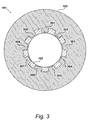
- FIG. 3 A cross sectional view of the brake disc 101 is shown in Figure 3 , along the line W-W identified in Figure 2A .
- the friction ring 102 is formed with inwardly directed castellations 301, 302, 303, 304, 305, 306, 307, 308, and 309 with spaces between them that are filled by the aluminium alloy when the hub 103 is cast. It will be appreciated that, for simplicity of illustration, only a few castellations 301 to 309 are shown in Figure 3 , and in practice there may be more.
- a brake disc 401 according to the present invention is illustrated in Figure 4 , which in the present embodiment is a solid disc brake for fitting to a passenger vehicle.
- Figure 4 A brake disc 401 according to the present invention is illustrated in Figure 4 , which in the present embodiment is a solid disc brake for fitting to a passenger vehicle.
- the principles of the present invention may be extended to ventilated disc brakes targeted at high performance applications.
- the brake disc 401 has a brake member 402 annular around an axis B (the axis of rotation of a road wheel or axle, not shown, as with brake disc 101 ), and a hub 403.
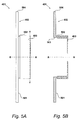
- the brake disc 401 is shown in an end-on view in Figure 5A , and in cross section through its axis B in Figure 5B .
- the differences between the present invention and the prior art brake disc 101 described with reference to Figures 1 to 4 are shown.
- the brake member 402 comprises a friction ring 501 annular about axis B.
- the friction ring 501 extends radially in a plane from an inner radius 503 to an outer radius 504.
- the brake member further comprises a hollow cylindrical flange 502 extending axially from the friction ring 501 (i.e. orthogonally from its plane).
- the inner radius 503 of the friction ring 501 is coterminous with the inside surface of the hollow cylindrical flange 502.
- the hub 403 extends axially over both the inner surface and the outer surface of the flange 502. That is to say, the hub 403 engages radially opposed surfaces of the flange 502 and thereby makes a connection between the hub 403 and the brake member 402.
- the radial flange 203 of the prior art brake disc 101 is necessarily limited in extent because of the need to leave enough of the friction ring 102 clear for the brake pads (not shown). This in turn limits the strength of the cast-on engagement between the prior art hub 103 and the prior art friction ring 102.
- the hub 403 is cast on to the axially extending flange 502 which does not have such a limitation in extent.
- the brake disc 401 according to the present invention has much improved strength over the prior art brake disc 101.
- the hub 403 of brake disc 401 is formed of a first material
- the brake member 402 is formed of a second material.
- the first material is selected so that it has a lower density, a lower melting point, and a higher coefficient of linear thermal expansion relative to the second material.
- the first material is iron or an alloy thereof, with the second material being selected so the above properties are satisfied.
- the second material is aluminium, or an alloy thereof, with the first material being selected so the above properties are satisfied.
- the first material is iron or an alloy thereof, and the second material is aluminium or an alloy thereof.
- the brake disc 401 of the present invention is manufactured by first pre-forming the brake member 402 using the selected second material. In the present embodiment, this is achieved in an embodiment by casting the brake member 402, such that the friction ring 501 and the flange 502 are integrally formed. The brake member 402 may then be machined it. Alternatively, the brake member 402 may be created by coupling a separately-cast friction ring 501 and flange 502 together in a known manner.
- the brake member 402 is then located in a mould having a cavity for the flange 502.
- the hub 403 is then cast onto the flange by delivering molten first material into the cavity to fill and engage with the flange.
- the hub 403 is then allowed to cool and solidify in the mould.
- the brake member 402 may be heated prior to delivery of the first material to improve the interface between the materials, and reduce any thermal shock caused by the addition of molten second material.
- the brake disc 401 comprising the hub 403 plus brake member 402 can be subject as a whole to further machining before it is fitted to a vehicle.
- the effect of selecting a first material which has a lower density than the second material is to reduce the overall weight of the brake disc 401, and thereby assist in reduction of unsprung weight, improving vehicle performance and fuel economy.
- the effect of selecting a first material which has a lower meting point than the second material is to allow it to be cast onto the pre-formed brake member 402.
- the effect of selecting a first material which has a higher coefficient of linear thermal expansion than the second material is to provide a better (and better protected) joint between the hub 403 and the brake member 402.
- the interface between two materials of differing electrode potential is liable to galvanic corrosion in the presence of an electrolyte, such as is the case when, for example, an aluminium alloy is cast on to grey cast iron.
- the second material of the hub 403 is specifically selected to have a higher coefficient of linear thermal expansion than the second material of the brake member 402.
- the hub 403 contracts more than the flange 502 as it cools after being cast. This, in combination with the hub 403 being arranged to extend over both the outer and inner surfaces of the flange 502, results in a tighter joint between the hub 403 and the flange 502 being formed.
- a cross sectional view of the brake disc 401 is shown in Figure 6 , along the line X-X identified in Figure 5A .
- the flange 502 is formed with axially-directed castellations 601, 602, 603, 604, 605, 606, 607, and 608 encapsulated in the casting of the hub 403. It will be appreciated that for simplicity of illustration, only a few castellations 601 to 608 are shown in Figure 6 , and in practice there may be more.
- Various additional features may be provided on the brake disc 401 to improve the general performance disc, and also improve the interface between the brake member 402 and the hub 403.
- FIG. 7 an embodiment of the brake disc 401 is shown in Figure 7 in which a circumferential channel 701 is provided at the join of the friction ring 501 and the flange 502.
- the inclusion of the circumferential channel 701 has been shown to reduce coning, which is a conical deformation of the friction ring 501 which acts to force the brake pads apart slightly, thereby changing the pressure distribution of the pad and reducing braking effectiveness.
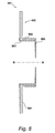
- FIG. 8 an embodiment of the brake disc 401 is shown in Figure 8 in which the casting of the hub 403 extends axially at 801 over the whole of the inside of the flange 502, through the inner radius of the friction ring 501 and radially outwards by a small amount. This extension of the casting of the hub 403 strengthens the axial connection with the brake member 402, allowing the brake disc 401 to withstand greater axial forces on the brake member 402.
- FIG. 9 an embodiment of the brake disc 401 is shown in Figure 9 in which the flange 502 is formed with outwardly extending nubs (or lumps) 901 and 902.
- the nubs 901 and 902 are encapsulated in the casting of the hub 403 to strengthen the circumferential connection. It will be appreciated that for simplicity of illustration, only two nubs 901 and 902 are visible in Figure 9 , but in practice there may be more. In an alternative embodiment, the nubs could be replaced by one single circumferential flange.
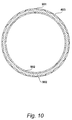
- a cross sectional view of the brake disc 401 is shown in Figure 10 , along the line Y-Y identified in Figure 9 .
- holes 1101 and 1102 extend axially and in the present embodiment, an even radial distribution of holes is included.
- the holes 1001 and 1002 are filled with the first material of the hub 403 and strengthen its circumferential connection with the flange 502 of the brake member 402
- FIG. 11 an embodiment of the brake disc 401 is shown in Figure 11 in which the flange 502 is formed with holes in it, such as holes 1101 and 1102.
- the holes are formed when casting the brake member 403 by inclusion of appropriate holes in its mold.
- the holes may be formed during the machining of the brake member 402.
- a cross sectional view of the brake disc 401 is shown in Figure 12 , along the line Z-Z identified in Figure 11 .
- holes 1101 and 1102 extend axially and in the present embodiment, an even radial distribution of holes is included.
- the holes 1101 and 1102 are filled with the first material of the hub 403 and strengthen its circumferential connection with the flange 502 of the brake member 402.
- the holes may be substituted for recesses extending only part way through the radial thickness of the flange 502, rather than completely therethrough as holes 1101 and 1102 do.
- Such recesses may either be recesses in the outer surface of the flange 502 or recesses in its inner surface.
- the axial castellations 601 to 608, the circumferential channel 701, the axially extended casting 801, the nubs 901 and 902 (or circumferential flange) and the holes 1101 and 1102 (or recesses) may be used together in any combination.
Landscapes
- Engineering & Computer Science (AREA)
- General Engineering & Computer Science (AREA)
- Mechanical Engineering (AREA)
- Braking Arrangements (AREA)
Abstract
A brake disc (401) for a vehicle having a hub (403) to be secured to a wheel or an axle of a vehicle, such that it will rotate about an axis (B). The brake disc also has a brake member (402) comprising an annular friction ring (501) having an inner radius (503) and an outer radius (504), and an axially extending hollow cylindrical flange (502) having an inner surface and an outer surface. The hub is a casting which extends over both the inner surface and the outer surface of the flange. The hub (403) is formed of a first material whilst the friction ring (501) is formed of a second material, and the first material has a lower density, a lower melting point, and a higher coefficient of linear thermal expansion than the second material.
Description
- This application claims priority from
United Kingdom Patent Application No. 15 06 523.8, filed 15 April 2015 - The present invention relates to brake discs for vehicles according to the preamble of
claim 1, and a method of manufacture of a brake disk according to the preamble of claim 11. - A brake disc of a vehicle comprises a friction ring that rotates with a ground-engaging wheel of the vehicle and is gripped by caliper-operated pads to slow the vehicle down when required. The friction ring must be able to resist both wear from the brake pads and heat generated by the braking. For these reasons friction rings are conventionally made of cast iron.
- However, as is well known, cast iron is a relatively heavy material for use in a sports car: it is, for instance, about two and a half times as heavy as aluminium. Therefore, to reduce the weight of the disc brake as a whole, the friction ring may be carried on a hub formed of lighter material such as aluminium or an aluminium alloy. The hub, sometimes known as a "top hat", is in use connected to the ground-engaging wheel or an axle of the wheel.
- This so-called "composite" form of construction (which should not be confused with the possible use of fibre-reinforced plastics materials) contrasts with monolithic forms in which the friction ring and the hub are integrally formed from the same material in that it requires a connection between the hub and the friction ring that will withstand both rotational forces in braking (and acceleration) and transverse forces in cornering. Various kinds of such connection have been previously proposed.
- It is known from
DE 10 2009 049 315 A1 andUS 8,844,685 B2 to cast the hub on to the friction ring whereby the friction ring and the hub are formed with castellations mutually intercalated in the plane of the friction ring. - It is also known from
US 2014/0151166 A1 to cast a hub onto a friction ring formed with axially extending teeth to create a coupling therebetween. The material used for the friction ring has a higher melting point than the material used for the hub. - It is also known from
EP 1 426 644 A2 - According to a first aspect of the present invention, there is provided a brake disc for a vehicle of the aforesaid type, having the characterising features set out in
claim 1. - According to a second aspect of the present invention, there is provided a method of manufacturing a brake disc of the aforesaid type having the characterising features set out in claim 11.
-
-
Figure 1 shows a priorart brake disc 101; -
Figure 2A is a side elevation of the priorart brake disc 101; -
Figure 2B is a vertical cross section of the priorart brake disc 101; -
Figure 3 is a cross section at W-W ofFigure 2A of the priorart brake disc 101; -
Figure 4 illustrates abrake disc 401 according to the present invention; -
Figure 5A is a side elevation of thebrake disc 401; -
Figure 5B is a vertical cross section of thebrake disc 401; -
Figure 6 is a cross section at X-X ofFigure 5A showing thebrake disc 401; -
Figure 7 is a vertical cross section of thebrake disc 401 including also acircumferential channel 701; -
Figure 8 is a vertical cross section ofbrake disc 401 including also ahub casting 801 that extends through thebrake member 402 and axially outwards; -
Figure 9 is a vertical cross section of thebrake disc 401 including also radially extendingnubs -
Figure 10 is a cross section at Y-Y ofFigure 9 showing the radially extendingnubs -
Figure 11 is a vertical cross section of thebrake disc 401 including alsoholes -
Figure 12 is a cross section at Z-Z ofFigure 11 showingholes - A
brake disc 101 of the prior art is shown inFigures 1 to 4 . - The
brake disc 101 comprises afriction ring 102 made of cast iron and ahub 103 made of cast aluminium alloy for connection to a road wheel or an axle of a vehicle (not shown). Thefriction ring 102 is annular about an axis A, which, when fitted to a vehicle, is the axis of rotation of the road wheel or axle. - The
brake disc 101 is shown in side elevation inFigure 2A , and in vertical cross section through its axis A inFigure 2B . - The
brake disc 101 has aninner radius 201 defined by thefriction ring 102, and anouter radius 202 defined by thehub 103. Thehub 103 is cast on to thefriction ring 102, and has a radially extendingflange 203 cast over the horizontally inner margins of thefriction ring 102. - A cross sectional view of the
brake disc 101 is shown inFigure 3 , along the line W-W identified inFigure 2A . - As shown in
Figure 3 , thefriction ring 102 is formed with inwardly directedcastellations hub 103 is cast. It will be appreciated that, for simplicity of illustration, only afew castellations 301 to 309 are shown inFigure 3 , and in practice there may be more. - A
brake disc 401 according to the present invention is illustrated inFigure 4 , which in the present embodiment is a solid disc brake for fitting to a passenger vehicle. However, it will be appreciated by those skilled in the art that the principles of the present invention may be extended to ventilated disc brakes targeted at high performance applications. - The
brake disc 401 has abrake member 402 annular around an axis B (the axis of rotation of a road wheel or axle, not shown, as with brake disc 101), and ahub 403. - The
brake disc 401 is shown in an end-on view inFigure 5A , and in cross section through its axis B inFigure 5B . In particular, the differences between the present invention and the priorart brake disc 101 described with reference toFigures 1 to 4 are shown. - The
brake member 402 comprises afriction ring 501 annular about axis B. Thefriction ring 501 extends radially in a plane from aninner radius 503 to anouter radius 504. The brake member further comprises a hollowcylindrical flange 502 extending axially from the friction ring 501 (i.e. orthogonally from its plane). Theinner radius 503 of thefriction ring 501 is coterminous with the inside surface of the hollowcylindrical flange 502. - The
hub 403 extends axially over both the inner surface and the outer surface of theflange 502. That is to say, thehub 403 engages radially opposed surfaces of theflange 502 and thereby makes a connection between thehub 403 and thebrake member 402. - It should be noted that the
radial flange 203 of the priorart brake disc 101 is necessarily limited in extent because of the need to leave enough of thefriction ring 102 clear for the brake pads (not shown). This in turn limits the strength of the cast-on engagement between theprior art hub 103 and the priorart friction ring 102. By contrast, in thebrake disc 401 of the present invention, thehub 403 is cast on to the axially extendingflange 502 which does not have such a limitation in extent. Thus thebrake disc 401 according to the present invention has much improved strength over the priorart brake disc 101. - Referring again to
Figure 5A , thehub 403 ofbrake disc 401 is formed of a first material, and thebrake member 402 is formed of a second material. In the present embodiment, the first material is selected so that it has a lower density, a lower melting point, and a higher coefficient of linear thermal expansion relative to the second material. - In an embodiment, the first material is iron or an alloy thereof, with the second material being selected so the above properties are satisfied. In another embodiment, the second material is aluminium, or an alloy thereof, with the first material being selected so the above properties are satisfied. In a specific embodiment, the first material is iron or an alloy thereof, and the second material is aluminium or an alloy thereof.
- In practice, following selection of the first and second materials in accordance with the above constraints, the
brake disc 401 of the present invention is manufactured by first pre-forming thebrake member 402 using the selected second material. In the present embodiment, this is achieved in an embodiment by casting thebrake member 402, such that thefriction ring 501 and theflange 502 are integrally formed. Thebrake member 402 may then be machined it. Alternatively, thebrake member 402 may be created by coupling a separately-cast friction ring 501 andflange 502 together in a known manner. - The
brake member 402 is then located in a mould having a cavity for theflange 502. Thehub 403 is then cast onto the flange by delivering molten first material into the cavity to fill and engage with the flange. Thehub 403 is then allowed to cool and solidify in the mould. Optionally, thebrake member 402 may be heated prior to delivery of the first material to improve the interface between the materials, and reduce any thermal shock caused by the addition of molten second material. - Those skilled in the art will appreciate that after the
hub 403 has been cast on to theflange 502, thebrake disc 401 comprising thehub 403 plusbrake member 402 can be subject as a whole to further machining before it is fitted to a vehicle. - The effect of selecting a first material which has a lower density than the second material is to reduce the overall weight of the
brake disc 401, and thereby assist in reduction of unsprung weight, improving vehicle performance and fuel economy. - The effect of selecting a first material which has a lower meting point than the second material is to allow it to be cast onto the
pre-formed brake member 402. - The effect of selecting a first material which has a higher coefficient of linear thermal expansion than the second material is to provide a better (and better protected) joint between the
hub 403 and thebrake member 402. As will be appreciated by those skilled in the art, the interface between two materials of differing electrode potential is liable to galvanic corrosion in the presence of an electrolyte, such as is the case when, for example, an aluminium alloy is cast on to grey cast iron. - In the present invention, the second material of the
hub 403 is specifically selected to have a higher coefficient of linear thermal expansion than the second material of thebrake member 402. Thus, during manufacture, thehub 403 contracts more than theflange 502 as it cools after being cast. This, in combination with thehub 403 being arranged to extend over both the outer and inner surfaces of theflange 502, results in a tighter joint between thehub 403 and theflange 502 being formed. - Not only does this result in a stronger joint that can be subjected to greater axial forces, it also results in an interface between the first material and second material that is better protected against the ingress of moisture which could function as an electrolyte and thereby give rise to galvanic corrosion.
- By contrast, the principal shrinkage of the
prior art hub 103 after casting will be away from theinner radius 503 of thefriction ring 102. This may cause weakening of the connection between theprior art hub 103 and the priorart friction ring 102 and hence a greater risk of moisture penetration and galvanic corrosion in use. - A cross sectional view of the
brake disc 401 is shown inFigure 6 , along the line X-X identified inFigure 5A . - As illustrated in
Figure 6 , in the present embodiment theflange 502 is formed with axially-directedcastellations hub 403. It will be appreciated that for simplicity of illustration, only afew castellations 601 to 608 are shown inFigure 6 , and in practice there may be more. - Various additional features may be provided on the
brake disc 401 to improve the general performance disc, and also improve the interface between thebrake member 402 and thehub 403. - First, an embodiment of the
brake disc 401 is shown inFigure 7 in which acircumferential channel 701 is provided at the join of thefriction ring 501 and theflange 502. The inclusion of thecircumferential channel 701 has been shown to reduce coning, which is a conical deformation of thefriction ring 501 which acts to force the brake pads apart slightly, thereby changing the pressure distribution of the pad and reducing braking effectiveness. - Second, an embodiment of the
brake disc 401 is shown inFigure 8 in which the casting of thehub 403 extends axially at 801 over the whole of the inside of theflange 502, through the inner radius of thefriction ring 501 and radially outwards by a small amount. This extension of the casting of thehub 403 strengthens the axial connection with thebrake member 402, allowing thebrake disc 401 to withstand greater axial forces on thebrake member 402. - Third, an embodiment of the
brake disc 401 is shown inFigure 9 in which theflange 502 is formed with outwardly extending nubs (or lumps) 901 and 902. Thenubs hub 403 to strengthen the circumferential connection. It will be appreciated that for simplicity of illustration, only twonubs Figure 9 , but in practice there may be more. In an alternative embodiment, the nubs could be replaced by one single circumferential flange. - A cross sectional view of the
brake disc 401 is shown inFigure 10 , along the line Y-Y identified inFigure 9 . - As can be seen, holes 1101 and 1102 extend axially and in the present embodiment, an even radial distribution of holes is included. Thus, during casting the holes 1001 and 1002 are filled with the first material of the
hub 403 and strengthen its circumferential connection with theflange 502 of thebrake member 402 - Finally, an embodiment of the
brake disc 401 is shown inFigure 11 in which theflange 502 is formed with holes in it, such asholes brake member 403 by inclusion of appropriate holes in its mold. In an alternative embodiment the holes may be formed during the machining of thebrake member 402. - A cross sectional view of the
brake disc 401 is shown inFigure 12 , along the line Z-Z identified inFigure 11 . - As can be seen, holes 1101 and 1102 extend axially and in the present embodiment, an even radial distribution of holes is included. Thus, during casting the
holes hub 403 and strengthen its circumferential connection with theflange 502 of thebrake member 402. - In an alternative embodiment, the holes may be substituted for recesses extending only part way through the radial thickness of the
flange 502, rather than completely therethrough asholes flange 502 or recesses in its inner surface. - It should be understood that the
axial castellations 601 to 608, thecircumferential channel 701, the axially extended casting 801, thenubs 901 and 902 (or circumferential flange) and theholes 1101 and 1102 (or recesses) may be used together in any combination.
Claims (15)
- A brake disc (401) for a vehicle, which brake disc comprises:a hub (403) securable to a wheel or an axle of the vehicle for rotation therewith about an axis (B); anda brake member (402) comprising an annular friction ring having an inner radius (503) and an outer radius (504), and an axially extending hollow cylindrical flange (502) having an inner surface and an outer surface;wherein the hub is formed of a first material and the friction ring is formed of a second material; characterised in that:the hub is a casting Which extends over the inner surface and the outer surface of the flange, andthe first material has a lower density, a lower melting point, and a higher coefficient of linear thermal expansion than the second material.
- A brake disc as claimed in claim 1, wherein the first material comprises aluminium or an alloy thereof.
- A brake disc as claimed in claim 1 or claim 2, wherein the second material comprises iron or an alloy thereof.
- A brake disc as claimed in any one of claims 1 to 3, wherein the friction ring (501) and the flange (502) are an integrally formed casting.
- A brake disc as claimed in any one of claims 1 to 4, wherein the flange is formed with axially extending castellations (602).
- A brake disc as claimed in any one of claims 1 to 5, wherein the hub (403) further extends (801) through the inner radius of the friction ring (501) and axially outwards.
- A brake disc as claimed in any one of claims 1 to 6, wherein the flange (502) includes one or more radially extending nubs (901, 902) which are encapsulated in the casting of the hub (403).
- A brake disc as claimed in any one of claims 1 to 7, wherein the flange (502) has one or more holes (1001, 1002) extending radially through the flange, which holes are filled with the first material.
- A brake disc as claimed any one of claims 1 to 8, wherein the flange (502) has one or more recesses extending radially part way through the flange, which recesses are filled with the first material.
- A vehicle comprising at least one brake disc as claimed in any one of claims 1 to 9.
- A method of manufacturing a brake disc (401) having a hub (403) of a first material and a brake member (402) of a second material, said method characterised by steps of:selecting a first material that has a lower density, a lower melting point, and a higher coefficient of linear thermal expansion than the second material;pre-forming the brake member as an annular friction ring (501) extending in a plane between an inner radius (503) and an outer radius (503) with a hollow cylindrical flange (502) extending orthogonally to the plane of the friction ring;providing a mould having a cavity configured to receive the flange of the preformed brake member, and wherein the cavity has the shape of the hub;locating the preformed brake member so that the flange is received in the cavity; andcasting the hub by delivering the first material in a molten state into the cavity to fill it and engage the flange, and allowing the first material to cool and solidify in the mould.
- A method of manufacturing a brake disc as claimed in claim 11, wherein the first material comprises aluminum or an alloy thereof, and the second material comprises iron or an alloy thereof.
- A method of manufacturing a brake disc as claimed in claim 11, wherein the step of pre-forming the brake member comprises casting and machining.
- A method of manufacturing a brake disc as claimed in claim 13, wherein the casting and machining of the brake member comprises forming at least one of:axially extending castellations on the flange;one or more radially extending nubs on the flange to be encapsulated in the casting of the hub;one or more holes in the flange to be filled by the first material during casting of the hub; andone or more recesses extending radially part way through the flange to be filled with the first material during casting of the hub.
- A method of manufacturing a brake disc as claimed in claim 11, further comprising the step of heating the brake member before delivering the first material into the cavity.
Applications Claiming Priority (1)
| Application Number | Priority Date | Filing Date | Title |
|---|---|---|---|
| GB1506523.8A GB2537411A (en) | 2015-04-15 | 2015-04-15 | Brake discs |
Publications (1)
| Publication Number | Publication Date |
|---|---|
| EP3081826A1 true EP3081826A1 (en) | 2016-10-19 |
Family
ID=53298728
Family Applications (1)
| Application Number | Title | Priority Date | Filing Date |
|---|---|---|---|
| EP16250008.6A Withdrawn EP3081826A1 (en) | 2015-04-15 | 2016-04-11 | Brake discs |
Country Status (4)
| Country | Link |
|---|---|
| US (1) | US20160305498A1 (en) |
| EP (1) | EP3081826A1 (en) |
| CN (1) | CN206320208U (en) |
| GB (1) | GB2537411A (en) |
Cited By (2)
| Publication number | Priority date | Publication date | Assignee | Title |
|---|---|---|---|---|
| GB2552568A (en) * | 2016-07-26 | 2018-01-31 | Eurac Ltd | Brake discs |
| CN108730366A (en) * | 2017-04-20 | 2018-11-02 | 马自达汽车株式会社 | Device is concluded in the friction of automatic transmission |
Families Citing this family (1)
| Publication number | Priority date | Publication date | Assignee | Title |
|---|---|---|---|---|
| CN112610631A (en) * | 2020-12-11 | 2021-04-06 | 山东卢斯得机械股份有限公司 | Fusion casting type brake disc and manufacturing method thereof |
Citations (2)
| Publication number | Priority date | Publication date | Assignee | Title |
|---|---|---|---|---|
| EP1426644A2 (en) * | 2002-11-16 | 2004-06-09 | Bayerische Motoren Werke Aktiengesellschaft | Assembled brake disc for a vehicle disc brake |
| US20070119667A1 (en) * | 2005-11-30 | 2007-05-31 | Hanna Michael D | Rotor assembly and method |
Family Cites Families (1)
| Publication number | Priority date | Publication date | Assignee | Title |
|---|---|---|---|---|
| IT1403905B1 (en) * | 2011-01-26 | 2013-11-08 | Freni Brembo Spa | DISC FOR DISC BRAKES |
-
2015
- 2015-04-15 GB GB1506523.8A patent/GB2537411A/en not_active Withdrawn
-
2016
- 2016-04-11 EP EP16250008.6A patent/EP3081826A1/en not_active Withdrawn
- 2016-04-13 US US15/098,045 patent/US20160305498A1/en not_active Abandoned
- 2016-04-14 CN CN201620317810.4U patent/CN206320208U/en not_active Expired - Fee Related
Patent Citations (2)
| Publication number | Priority date | Publication date | Assignee | Title |
|---|---|---|---|---|
| EP1426644A2 (en) * | 2002-11-16 | 2004-06-09 | Bayerische Motoren Werke Aktiengesellschaft | Assembled brake disc for a vehicle disc brake |
| US20070119667A1 (en) * | 2005-11-30 | 2007-05-31 | Hanna Michael D | Rotor assembly and method |
Cited By (7)
| Publication number | Priority date | Publication date | Assignee | Title |
|---|---|---|---|---|
| GB2552568A (en) * | 2016-07-26 | 2018-01-31 | Eurac Ltd | Brake discs |
| EP3290735A1 (en) * | 2016-07-26 | 2018-03-07 | Eurac Limited | Brake discs |
| GB2552568B (en) * | 2016-07-26 | 2019-03-20 | Eurac Ltd | Brake discs |
| US10352381B2 (en) | 2016-07-26 | 2019-07-16 | Eurac Limited | Brake discs |
| CN108730366A (en) * | 2017-04-20 | 2018-11-02 | 马自达汽车株式会社 | Device is concluded in the friction of automatic transmission |
| CN108730366B (en) * | 2017-04-20 | 2020-03-24 | 马自达汽车株式会社 | Friction fastening device for automatic transmission |
| US10655694B2 (en) | 2017-04-20 | 2020-05-19 | Mazda Motor Corporation | Friction engagement device of automatic transmission |
Also Published As
| Publication number | Publication date |
|---|---|
| CN206320208U (en) | 2017-07-11 |
| US20160305498A1 (en) | 2016-10-20 |
| GB2537411A (en) | 2016-10-19 |
| GB201506523D0 (en) | 2015-06-03 |
Similar Documents
| Publication | Publication Date | Title |
|---|---|---|
| EP2558737B1 (en) | A flanged bearing ring for a motor vehicle wheel bearing unit | |
| US8962148B2 (en) | Lightweight brake rotor and components with composite materials | |
| US6073735A (en) | Brake disc | |
| US9174274B2 (en) | Low mass multi-piece sound dampened article | |
| US5862892A (en) | Composite rotor for caliper disc brakes | |
| US8967339B2 (en) | Brake disc arrangement for disc brakes | |
| US10352381B2 (en) | Brake discs | |
| US7861832B2 (en) | Thermally accommodating interconnection for cast-in-place components | |
| JP7010490B2 (en) | Vehicle wheels | |
| US20120186919A1 (en) | Molded Components Having a Visible Designer Feature and/or Improved Operational Properties via a Porous Preform | |
| WO2007146720A2 (en) | Brake disc assembly and method of construction | |
| US20110255819A1 (en) | Flanged Bearing Ring for a Motor Vehicle Wheel Bearing Unit | |
| KR101972270B1 (en) | Intergral Type Hybrid Brake Disc of Lightweight with improved heat radiation characteristics for car and its manufacturing method | |
| US20160305498A1 (en) | Brake discs | |
| CN108087460B (en) | Solid brake disc and method for producing same | |
| US9546683B2 (en) | Flanged bearing ring for a motor vehicle wheel bearing unit | |
| EP2980436B1 (en) | Disc for disc brakes and process for manufacturing the same | |
| US11124033B2 (en) | Dampener insert | |
| JP2009161166A (en) | Movement prevention collar of casting metal for stabilizer and manufacturing method | |
| WO2012003848A1 (en) | Flanged hub of a wheel bearing unit | |
| US20210364053A1 (en) | Thermal management of metal matrix composite systems | |
| US20100025169A1 (en) | Brake disk for a disk brake | |
| US20140326551A1 (en) | Composite rotor | |
| CN106605078A (en) | Disc brake with energizing ring | |
| KR20220126596A (en) | Brake disc manufacturing method |
Legal Events
| Date | Code | Title | Description |
|---|---|---|---|
| PUAI | Public reference made under article 153(3) epc to a published international application that has entered the european phase |
Free format text: ORIGINAL CODE: 0009012 |
|
| AK | Designated contracting states |
Kind code of ref document: A1 Designated state(s): AL AT BE BG CH CY CZ DE DK EE ES FI FR GB GR HR HU IE IS IT LI LT LU LV MC MK MT NL NO PL PT RO RS SE SI SK SM TR |
|
| AX | Request for extension of the european patent |
Extension state: BA ME |
|
| STAA | Information on the status of an ep patent application or granted ep patent |
Free format text: STATUS: THE APPLICATION HAS BEEN PUBLISHED |
|
| STAA | Information on the status of an ep patent application or granted ep patent |
Free format text: STATUS: THE APPLICATION IS DEEMED TO BE WITHDRAWN |
|
| 18D | Application deemed to be withdrawn |
Effective date: 20170420 |