EP3290592A1 - Verfahren und vorrichtung zur verfolgung einer klinge - Google Patents
Verfahren und vorrichtung zur verfolgung einer klinge Download PDFInfo
- Publication number
- EP3290592A1 EP3290592A1 EP17188896.9A EP17188896A EP3290592A1 EP 3290592 A1 EP3290592 A1 EP 3290592A1 EP 17188896 A EP17188896 A EP 17188896A EP 3290592 A1 EP3290592 A1 EP 3290592A1
- Authority
- EP
- European Patent Office
- Prior art keywords
- blade
- camera
- optical target
- optical
- imaging data
- Prior art date
- Legal status (The legal status is an assumption and is not a legal conclusion. Google has not performed a legal analysis and makes no representation as to the accuracy of the status listed.)
- Granted
Links
Images


Classifications
-
- E—FIXED CONSTRUCTIONS
- E02—HYDRAULIC ENGINEERING; FOUNDATIONS; SOIL SHIFTING
- E02F—DREDGING; SOIL-SHIFTING
- E02F3/00—Dredgers; Soil-shifting machines
- E02F3/04—Dredgers; Soil-shifting machines mechanically-driven
- E02F3/76—Graders, bulldozers, or the like with scraper plates or ploughshare-like elements; Levelling scarifying devices
- E02F3/7636—Graders with the scraper blade mounted under the tractor chassis
-
- G—PHYSICS
- G01—MEASURING; TESTING
- G01C—MEASURING DISTANCES, LEVELS OR BEARINGS; SURVEYING; NAVIGATION; GYROSCOPIC INSTRUMENTS; PHOTOGRAMMETRY OR VIDEOGRAMMETRY
- G01C9/00—Measuring inclination, e.g. by clinometers, by levels
- G01C9/02—Details
- G01C9/06—Electric or photoelectric indication or reading means
-
- E—FIXED CONSTRUCTIONS
- E02—HYDRAULIC ENGINEERING; FOUNDATIONS; SOIL SHIFTING
- E02F—DREDGING; SOIL-SHIFTING
- E02F3/00—Dredgers; Soil-shifting machines
- E02F3/04—Dredgers; Soil-shifting machines mechanically-driven
- E02F3/76—Graders, bulldozers, or the like with scraper plates or ploughshare-like elements; Levelling scarifying devices
- E02F3/80—Component parts
- E02F3/84—Drives or control devices therefor, e.g. hydraulic drive systems
- E02F3/844—Drives or control devices therefor, e.g. hydraulic drive systems for positioning the blade, e.g. hydraulically
- E02F3/847—Drives or control devices therefor, e.g. hydraulic drive systems for positioning the blade, e.g. hydraulically using electromagnetic, optical or acoustic beams to determine the blade position, e.g. laser beams
-
- E—FIXED CONSTRUCTIONS
- E02—HYDRAULIC ENGINEERING; FOUNDATIONS; SOIL SHIFTING
- E02F—DREDGING; SOIL-SHIFTING
- E02F9/00—Component parts of dredgers or soil-shifting machines, not restricted to one of the kinds covered by groups E02F3/00 - E02F7/00
- E02F9/26—Indicating devices
- E02F9/264—Sensors and their calibration for indicating the position of the work tool
- E02F9/265—Sensors and their calibration for indicating the position of the work tool with follow-up actions (e.g. control signals sent to actuate the work tool)
-
- G—PHYSICS
- G06—COMPUTING OR CALCULATING; COUNTING
- G06T—IMAGE DATA PROCESSING OR GENERATION, IN GENERAL
- G06T7/00—Image analysis
- G06T7/70—Determining position or orientation of objects or cameras
-
- H—ELECTRICITY
- H04—ELECTRIC COMMUNICATION TECHNIQUE
- H04N—PICTORIAL COMMUNICATION, e.g. TELEVISION
- H04N7/00—Television systems
- H04N7/18—Closed-circuit television [CCTV] systems, i.e. systems in which the video signal is not broadcast
-
- E—FIXED CONSTRUCTIONS
- E02—HYDRAULIC ENGINEERING; FOUNDATIONS; SOIL SHIFTING
- E02F—DREDGING; SOIL-SHIFTING
- E02F9/00—Component parts of dredgers or soil-shifting machines, not restricted to one of the kinds covered by groups E02F3/00 - E02F7/00
- E02F9/20—Drives; Control devices
- E02F9/2025—Particular purposes of control systems not otherwise provided for
- E02F9/2041—Automatic repositioning of implements, i.e. memorising determined positions of the implement
-
- G—PHYSICS
- G01—MEASURING; TESTING
- G01C—MEASURING DISTANCES, LEVELS OR BEARINGS; SURVEYING; NAVIGATION; GYROSCOPIC INSTRUMENTS; PHOTOGRAMMETRY OR VIDEOGRAMMETRY
- G01C11/00—Photogrammetry or videogrammetry, e.g. stereogrammetry; Photographic surveying
- G01C11/04—Interpretation of pictures
- G01C11/06—Interpretation of pictures by comparison of two or more pictures of the same area
-
- G—PHYSICS
- G06—COMPUTING OR CALCULATING; COUNTING
- G06T—IMAGE DATA PROCESSING OR GENERATION, IN GENERAL
- G06T2207/00—Indexing scheme for image analysis or image enhancement
- G06T2207/30—Subject of image; Context of image processing
- G06T2207/30248—Vehicle exterior or interior
- G06T2207/30252—Vehicle exterior; Vicinity of vehicle
Definitions
- This disclosure relates generally to working machines, and, more particularly, to methods and apparatus to track a blade.
- a blade such as a motor grader blade may be used to grade and/or condition a ground.
- Some known blade tracking/monitoring systems use positional sensors and/or a global positioning system (GPS) to track a location and/or movement of a blade and/or a working edge of the blade such that positional measurements can be made within an order of a few millimeters (mm).
- GPS global positioning system
- Some of these known imaging systems use vision systems to track a reticle or target of a working edge by obtaining images of the target and translating a vision system coordinate system to a navigation coordinate system that may be based on GPS. Some other known systems use laser guidance systems to track the working edge. These systems, however, may be limited in terms of reliability of positional/rotational determinations (e.g., dust and/or other environmental factors that may inhibit image recognition) and cameras of these systems may only be able to make visual measurements within a limited range of motion. Further, many of these known positional tracking systems can be relatively expensive.
- any part is in any way positioned on (e.g., positioned on, located on, disposed on, or formed on, etc.) another part, means that the referenced part is either in contact with the other part, or that the referenced part is above the other part with one or more intermediate part(s) located therebetween. Stating that any part is in contact with another part means that there is no intermediate part between the two parts.
- An example apparatus includes a blade that is pivotable, first and second optical targets operatively coupled to the blade, and a first camera for collecting first imaging data of the first optical target within a first field of view.
- the example apparatus also includes a second camera for collecting second imaging data of the second optical target within a second field of view.
- the example apparatus also includes a selector to select the first or second imaging data, and a processor to determine an orientation of the blade based on the selected first or second imaging data.
- An example method includes visually measuring locations of first and second optical targets, where the first and second optical targets are operatively coupled to a blade that is pivotable, selecting visual location measurements of the first optical target or the second optical target, and determining a position and an orientation of the blade based on the selected visual location measurements.
- An example tangible machine readable medium includes instructions, which when executed, cause a processor of a portable device to at least select a visual location measurement of a first optical target or a second optical target, where the first and second optical targets are operatively coupled to a blade that is pivotable, and determine a visual position of the blade based on the selected visual location measurement.
- An example vehicle includes a working implement that is pivotable and movable in multiple degrees of freedom, and an optical target operatively coupled to the working implement, where the optical target includes an array of a plurality of circles arranged in a pattern.
- the example vehicle also includes a camera for collecting imaging data of the optical target, and a processor to determine a position and an orientation of the working implement based on the imaging data.
- a blade such as a motor grader blade or other working implement, may be used to grade and/or condition a work surface, work site and/or Earth.
- Some known blade tracking/monitoring systems use positional sensors and/or a global positioning system (GPS) to track a location and/or movement of a blade that can measure movement of the blade within approximately 30 millimeters (mm).
- GPS global positioning system
- Laser guidance systems have also been used to track blade movement.
- these known laser and GPS systems can be relatively expensive and complex (e.g., requiring numerous different integrated systems such as power systems, GPS systems, coordinating software, etc.).
- Some other known image tracking systems use cameras to track a reticle or target of a pivotable and translatable working edge by obtaining images of the target and translate a vision system coordinate system to a navigation coordinate system that is based on GPS.
- These image tracking systems may be limited in terms of reliability of position determinations (e.g., dust and/or other environmental factors may inhibit image recognition) and cameras of these systems may only be able to make visual measurements within a limited range of motion.
- these known systems may not be able to track movement in one or more degrees of freedom of a blade.
- the examples disclosed herein enable a cost-effective method of accurately determining a position of a working blade, which can be moved, pivoted, rotated and/or translated in multiple degrees of freedom (e.g., seven degrees of freedom).
- the examples disclosed herein utilize imaging systems (e.g., camera systems) in combination with optical targets that are mounted and/or coupled to the working blade to monitor and/or measure/track the position and/or rotational movement of the blade.
- visual data/information corresponding to an optical target of a plurality of optical targets is selected from amongst multiple optical targets to determine a position and rotation of a working blade.
- an optical target within a visual range of a camera may be selected and visually measured/analyzed to determine a position and rotation of the working blade.
- the examples disclosed herein may enable a measured accuracy on the order of 1 mm or less.
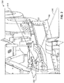
- FIG. 1 illustrates a working machine 100 in which the examples disclosed herein may be implemented.
- the working machine 100 of the illustrated example which is depicted as a motor grader in this example, includes a working blade 102, a cab 104, an engine portion 108, a pivot portion (e.g., a steering portion) 112 and wheels 114.
- the example working blade 102 can pivot and displace relative to the pivot portion 112 in multiple degrees of freedom. In this example, the blade 102 moved/rotated via an actuator 116.
- an operator of the illustrated example directs the working machine 100 from the cab 104 and as the working machine 100 is moved along the work site, the blade 102 is positioned and rotated appropriately to affect at least one condition of the ground.
- the blade 102 is moved/pivoted by the actuator 116 against the ground to shape and/or re-shape the ground (e.g., grade the ground).
- the pivot portion 112 rotates to steer the working machine 100 while the engine portion 108 propels the working machine 100 in a forward or reverse direction.
- the blade 102 is controlled (e.g., actuated) in numerous positions (e.g., downward and upward) as well as rotational directions (e.g., relative to the front portion 112, relative to the ground, etc.). Because grading the ground may be vital to construction, it may be necessary to control the blade 102 within a few millimeters (e.g., to at least within 30 millimeters) in some applications.
- the working machine 100 may be any appropriate vehicle and/or heavy equipment including, but not limited to, bull dozers, harvesters, back hoes, excavators, loaders, compactors, conveyors and/or agricultural equipment, etc. While the blade 102 is described in the illustrated example, any of the examples disclosed herein may be applied to any appropriate working implement.
- FIG. 2 is an example displacement monitoring system 200 in accordance with the teachings of this disclosure.
- the displacement monitoring system 200 includes a camera 202 (also shown/depicted as cameras 202a, 202b, etc. in subsequent figures) and an optical target 204, which is operatively and/or mechanically coupled to the blade 102.
- the camera 202 may be an IDS gigE UEye Re camera (UI-5490RE) with Computaar 8 mm 1:1.4 2/3 lens.
- UI-5490RE IDS gigE UEye Re camera
- Computaar 8 mm 1:1.4 2/3 lens Computaar 8 mm 1:1.4 2/3 lens.
- any appropriate camera/lens combination may be used.
- the blade 102 is supported by a support (e.g., a coupling support) 208 and shown rotated away from a default centered home position, which is described below in connection with FIGS. 5A and 5B .
- the camera 202 of the illustrated example defines a corresponding field of view, as generally indicated by lines 210.
- the camera 202 has an approximate angular viewing range of approximately 50 degrees. However, any appropriate angular viewing range angle may be used based on a specific application/use.
- the camera 202 of the illustrated example monitors and/or visually/optically measures the optical target 204, as will be discussed in greater detail below in connection with FIGS. 3-12 .
- the example blade 102 of the illustrated example is able to pivot away from the respective field of view of the camera 202, it can be desirable and/or advantageous to measure the blade 102 at another camera and/or camera position from that shown in FIG. 2 when the blade 102 has moved/rotated out of a visual range and/or a desired visual range.
- the relative positioning of the optical target 204 to the blade 102 allows detection of the optical target 204 even when the blade 102 moves towards the front tires 114.
- an outer edge (e.g., an outer lateral edge) 212 and/or distal end portion of the blade 102 may more accurately indicate a position and/or rotation of the blade 102 than measuring a portion of the blade 102 closer to its respective pivot (e.g., a center of the blade 102, a pivoting center, etc.) due to a larger relative movement of the blade 102 at the distal end portion.
- the examples disclosed herein enable monitoring of displacement as well as rotation of the blade 102 even when the blade 102 along with the optical target 204 has moved out of a visual detection/measurement range of the camera 202 shown in FIG. 2 without costly positional detection systems (e.g., laser-based systems).
- the examples disclosed herein also enable measurement of point(s) and/or visual identifiers proximate the outer edge 212 of the blade 102.
- FIG. 3 is a simplified overhead view depicting camera detection ranges of the example displacement monitoring system 200 of FIG. 2 .
- a camera 202a has a corresponding first field of view (e.g., visual range) 302a and a first non-detection area 304a in which the camera 202a cannot detect and/or accurately detect the optical target 204.
- the camera 202b has a corresponding second field of view 302b and a second non-detection area 304b.
- the first field of view 302a is separated from the first non-detection area 304a by a center line 306.
- the second field of view 302b is also separated from the second non-detection area 304b by the center line 306.
- the displacement monitoring system 200 of the illustrated example captures data from the camera 202a or the camera 202b when a portion of the blade 102 (e.g., a portion that extends beyond an axis of rotation of the blade 120) is rotated within either the first field of view 302a or the second field of view 302b.
- the example displacement monitoring system 200 switches between using and/or acquiring data from the camera 202a or the camera 202b based on an ability of the respective camera 202a or the camera 202b to properly/accurately detect the respective optical target 204.
- At least one of the cameras 202a, 202b can measure a position and rotation of the blade 102 when the other of the cameras 202a, 202b cannot detect its respective optical target 204.
- both of the cameras 202a, 202b are able to detect their respective optical target 204 when the blade 102 is positioned at the center line 306.
- the cameras 202a, 202b have an overlap visual detection range in this example.
- any appropriate number of cameras may be used as appropriate (e.g., 3, 4, 5... etc.).
- additional cameras may be placed towards a rear portion of the working machine 100 such as the engine portion 108 (e.g., on an opposite side of the working machine 100 from the cameras 202a, 202b) to cover the non-detection areas (e.g., blind spots) 304a, 304b.
- any of the visual ranges 302a, 302b may be altered and/or revised based on a detected articulation/relative displacement of the working machine 100 and/or a portion of the working machine 100.
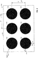
- FIG. 4 is a front view illustrating the example optical target 204 of the example displacement monitoring system 200 of FIG. 2 .
- the optical target 204 includes an array of circular targets 402 and is defined by a generally rectangular border 404.
- two rows of the three circular targets 402 are used to calculate a position of the blade 102.
- the circular targets 402 have a relatively dark color (e.g., black) while a background surrounding the circular targets 402 has a relatively light color (e.g., white, gray, off-white, etc.) to provide a significant contrast that can be easily detected by cameras in dusty and/or obscured conditions, for example.
- the circular targets 402 are flat-bed printed onto a magnetic sheet that is then affixed to a steel plate.
- the steel plate is held to the blade 102 by heavy-capacity magnets at four points, for example.
- a size and location of the circular targets 402 is improved and/or optimized for positional detection based on a two variable optimization that increases and/or maximizes both an area of the circular targets 402 as well as a distance between the circular targets 402 based on a specific application and/or desired use.
- the optical target 204 is approximately 15 inches (") wide by 10" tall.
- Dimensions 410 and 412, which are denoted by “X” and Y,” respectively, are approximately 4.75" while dimensions 414, denoted by “Z,” are approximately 1".
- diameter 416, which is denoted by " ⁇ D,” is approximately 3.5".
- the dimensions described in this example are only examples and any appropriate dimensions and/or size ratios may be used according to application, component size(s), visibility, etc.
- the circular targets 402 are shown with a darker color, in some examples, the background is a darker color than the circular targets 402 (e.g., a black background with white or gray circular targets 402, etc.). In other examples, the circular targets may not have a significantly different color from the background (e.g., only a line segment defines each of the circular targets 402). While the circular targets 402 are round and/or ellipsoid in this example, the circular targets 402 may be any appropriate shape (e.g., a triangular shape, a square shape, a pentagon shape or any appropriate polygon shape).
- the array of circular targets 402 may be directly provided and/or printed onto the blade 102 (e.g., without assembling a part/assembly).
- the optical target 204 is disposed on (e.g., directly printed on) a contour (e.g., a non-flat surface) of the blade 102.
- FIG. 5A is an overhead view of the example working machine 100 of FIG. 1 that depicts an example centering coordinate reference system that may be used in the examples disclosed herein.
- the blade 102 is shown in a default/centered position (e.g., a home position).
- a displacement, which encompasses translation as well as rotation, of the blade 102 is calculated/translated into a vehicle coordinate system, which is depicted in FIG. 5A as a vehicle coordinate system origin 502.
- the example vehicle coordinate system origin 502 represents an assumed coordinate system origin in three dimensions.
- FIG. 5A also depicts a rotational pivot point 504 of the blade 102, in which the blade 102 may rotate about, as generally indicated by an arrow 508.
- the rotational pivot 504 is located on the front portion 112 of the working machine 100.
- the blade 102 is centered at its default position, as indicated by a line 510.
- the vehicle coordinate system origin 502 is used in conjunction with a navigation system (e.g., a GPS system) to relate a movement of the blade 102 as the blade 102 is actuated during grading, for example.
- a navigation system e.g., a GPS system
- FIG. 5B is an isometric partial view further illustrating the example default centered position of the blade 102 of the example working machine 100 of FIG. 1 in additional degrees of freedom of movement from that shown in FIG. 5A .
- a second pivot axis 520 defines yet another rotational movement, as generally indicated by an arrow 522.
- a third pivot axis 524 defines another rotational movement (e.g., a downward and upward tilt), as generally indicated by an arrow 526.
- camera parameters of the illustrated example are calibrated using a toolbox of a calibration module that takes multiple camera images of a planar checkerboard and computes the internal camera parameters such as focal length, principal point, skew coefficients, and/or distortions.
- the skew coefficient is approximately zero if the pixels are rectangular Further, ( x c , y c ) represent the "true" pixel coordinates, and ( x i , y i ) represent the distorted image pixel coordinates.
- a first assumption is that no distortion is present, and, as a result, intrinsic and extrinsic parameters are computed for each image of the checkerboard.
- the world reference frame is centered at the upper left-hand corner of the optical target 204.
- the intrinsic parameters are focal length, principal point, skew coefficients, and/or distortions.
- the extrinsic parameters of the illustrated example are the rotation and translation of the camera relative to a world reference (e.g., a GPS reference coordinate system, a site reference coordinate system, etc.).
- the aforementioned example toolbox receives all the computed parameters and utilizes these parameters to estimate the true value of the parameters, including distortion, using a nonlinear least-squares minimization of the estimation error.
- the toolbox of the illustrated example then improves (e.g., optimizes) the parameters using the solutions from each checkerboard, and provides the final computed intrinsic parameters and the standard estimation errors.
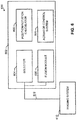
- FIG. 6 is an example displacement detection analysis system 600 that may be used to implement the example disclosed herein.
- the system 600 may incorporate and/or be implemented by the example architecture 700 or the example architecture 800 described below in connection with FIGS. 7 and 8 , respectively.
- the example detection analysis system 600 includes a tracking engine 602, which includes a selector 604, a position/rotation calculator 606 and an actuator control system 608.
- the tracking engine 602 is communicatively coupled to an imaging system 610 via a communication line 612.
- the tracking engine 602 determines and/or calculates a position as well as a rotation of the blade 102 while the working machine 100 is in operation.
- the selector 604 receives image data from multiple cameras/imaging sensors of the imaging system 610 and selects the image data and/or corresponding positional/rotational data of the blade 102 to be used for determining the position and the orientation of the blade 102.
- the selector 604 utilizes a confidence index of each camera of the imaging system 610 to select the camera data to be used in determining the position and/or rotation of the blade 102.
- the position/rotation calculator 606 of the illustrated example is used to calculate the position and rotation of the blade 102 based on the image data. This process is described in greater detail below in connection with FIGS. 9-12 .
- the position/rotation calculator 606 utilizes images of the respective optical targets 204 to calculate translation as well as orientation of the blade 102 in multiple degrees of freedom.
- the actuator control system 608 controls movement of the blade 102 (e.g., both rotation and displacement along multiple degrees of freedom) as the working machine 100 moves along a work site, for example.
- the actuator control system 608 controls movement of the blade 102 to alter a landscape of the worksite without the need for manual control/input by an operator.
- the example actuator control system 608 may take into account measured ground conditions, ground data and/or GPS positional data to control the blade 102.
- the example imaging system 610 includes numerous cameras or other optical sensors used to determine the translation and orientation of the optical target 204 and, in turn, the blade 102.
- the imaging system 610 generates and forwards image data from both cameras 202a, 202b while the example selector 604 selects the pertinent image data so that the position/rotation calculator 606 may determine/calculate the position/rotation of the blade 102 while excluding (e.g., ignoring) data from an other (i.e., an unselected) of the cameras 202a, 202b, for example.
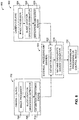
- FIG. 7 is a schematic overview of an example architecture (e.g., an image processing/selecting architecture) 700 that may be used to implement the example displacement detection analysis system 600 of FIG. 6 .
- the architecture 700 includes a first camera 702, which is designated as a "slave” in this example and includes an image processor 706, a blade location orientation estimator 708 and an estimation confidence engine 710.
- the example architecture 700 also includes a second camera 720, which is designated as a "master” in this example and includes an image processor 722, a blade location/orientation estimator 724, an estimation confidence engine 726, an estimation selector 728 and a machine coordinate system convertor 730.
- the second camera 720 is communicatively coupled to a downstream processing/control module 732 in addition to the first camera 702.
- both of the image processors 706, 722 receive image data and/or images from respective cameras and, in turn, provide the image data to the blade location estimators 708, 724, respectively.
- the blade location estimators 708, 724 of the illustrated example utilize this received image data to calculate/determine a displacement/location and orientation (e.g., in multiple degrees of freedom) of the blade 102. Examples of determinations of the displacement/translation and the orientation are described below in greater detail in connection with FIGS. 9-12 .
- the blade location estimators 708, 724 After determining the displacement and the orientation of the blade 102, provide their respective calculated displacement/translation and orientation to the estimation confidence engines 710, 726, respectively, to determine the displacement and orientation of the blade 102.
- the estimation selector 728 selects which calculated displacement/location and orientation to indicate movement/tracking of the blade 102.
- the estimation selector 728 of the illustrated example compares estimation confidences between both of the cameras 702, 720 to select which respective image data and/or corresponding blade location/orientation estimate to be used to track (e.g., periodically track) the blade 102.
- the downstream processing unit 732 determines/calculates the movement of the blade and/or estimation confidences (e.g., confidence factors).
- the first camera 602 does not provide an estimated displacement or orientation of the blade 102 and, instead, the blade location/orientation estimator 724 calculates the displacement and/or orientation of the blade 102.
- FIG. 8 is a schematic overview of an alternative example architecture 800 that may be used to implement the the example displacement detection analysis system 600 of FIG. 6 .
- the architecture 800 of the illustrated example includes multiple cameras in a "slave" configuration.
- the example architecture 800 includes the first camera 702 of FIG. 7 as well as a second camera 802, which includes an image processor 804, a blade location orientation estimator 806 and an estimation confidence engine 808.
- the architecture 800 of the illustrated example instead, includes an external processing unit (e.g., an external visual data processing unit) 820, which includes an estimation selector 822 and a machine coordinate system converter 824.
- the external processing unit 820 is communicatively coupled to the aforementioned downstream processing/control module 732.
- the example estimator selector 822 is communicatively coupled to both the estimation confidence engine 710 and the estimation confidence engine 808.
- the estimation selector 822 of the external processing unit 820 selects the visual data and/or respective blade location/orientation estimate calculated from image data received from either of the cameras 702, 802 (e.g., from the blade location estimator 708 or the blade location estimator 806) that is to be used in determining/calculating the position and/or rotation of the blade 102.
- the machine coordinate system convertor converts the image data to a position and/or rotation of the blade 102 in the coordinate system origin 502 and conveys the calculated data to the downstream processing/control module 732.
- FIGS. 7-12 While an example manner of implementing the displacement detection analysis system 600 of FIG. 6 is illustrated in FIGS. 7-12 , one or more of the elements, processes and/or devices illustrated in FIGS. 7-12 may be combined, divided, re-arranged, omitted, eliminated and/or implemented in any other way. Further, the example tracking engine 602, the example selector 604, the example actuator system 608, the example imaging system 610, and/or, more generally, the example displacement detection analysis system 600 of FIG. 6 may be implemented by hardware, software, firmware and/or any combination of hardware, software and/or firmware.
- any of the example tracking engine 602, the example selector 604, the example actuator system 608, the example imaging system 610 and/or, more generally, the example displacement detection analysis system 600 could be implemented by one or more analog or digital circuit(s), logic circuits, programmable processor(s), application specific integrated circuit(s) (ASIC(s)), programmable logic device(s) (PLD(s)) and/or field programmable logic device(s) (FPLD(s)).
- ASIC application specific integrated circuit
- PLD programmable logic device
- FPLD field programmable logic device
- At least one of the example tracking engine 602, the example selector 604, the example actuator system 608 and/or the example imaging system 610 is/are hereby expressly defined to include a tangible computer readable storage device or storage disk such as a memory, a digital versatile disk (DVD), a compact disk (CD), a Blu-ray disk, etc. storing the software and/or firmware.
- the example displacement detection analysis system 600 of FIG. 6 may include one or more elements, processes and/or devices in addition to, or instead of, those illustrated in FIGS. 7-12 , and/or may include more than one of any or all of the illustrated elements, processes and devices.
- the machine readable instructions comprise a program for execution by a processor such as the processor 1312 shown in the example processor platform 1300 discussed below in connection with FIG. 13 .
- the program may be embodied in software stored on a tangible computer readable storage medium such as a CD-ROM, a floppy disk, a hard drive, a digital versatile disk (DVD), a Blu-ray disk, or a memory associated with the processor 1312, but the entire program and/or parts thereof could alternatively be executed by a device other than the processor 1312 and/or embodied in firmware or dedicated hardware.
- example program is described with reference to the flowcharts illustrated in FIGS. 9-12 , many other methods of implementing the example displacement detection analysis system 600 may alternatively be used.
- order of execution of the blocks may be changed, and/or some of the blocks described may be changed, eliminated, or combined.
- FIGS. 9-12 may be implemented using coded instructions (e.g., computer and/or machine readable instructions) stored on a tangible computer readable storage medium such as a hard disk drive, a flash memory, a read-only memory (ROM), a compact disk (CD), a digital versatile disk (DVD), a cache, a random-access memory (RAM) and/or any other storage device or storage disk in which information is stored for any duration (e.g., for extended time periods, permanently, for brief instances, for temporarily buffering, and/or for caching of the information).
- a tangible computer readable storage medium such as a hard disk drive, a flash memory, a read-only memory (ROM), a compact disk (CD), a digital versatile disk (DVD), a cache, a random-access memory (RAM) and/or any other storage device or storage disk in which information is stored for any duration (e.g., for extended time periods, permanently, for brief instances, for temporarily buffering, and/or for caching of the information).
- tangible computer readable storage medium and “tangible machine readable storage medium” are used interchangeably. Additionally or alternatively, the example processes of FIGS. 9-12 may be implemented using coded instructions (e.g., computer and/or machine readable instructions) stored on a non-transitory computer and/or machine readable medium such as a hard disk drive, a flash memory, a read-only memory, a compact disk, a digital versatile disk, a cache, a random-access memory and/or any other storage device or storage disk in which information is stored for any duration (e.g., for extended time periods, permanently, for brief instances, for temporarily buffering, and/or for caching of the information).
- coded instructions e.g., computer and/or machine readable instructions
- a non-transitory computer and/or machine readable medium such as a hard disk drive, a flash memory, a read-only memory, a compact disk, a digital versatile disk, a cache, a random-access memory and/or any other storage device or storage disk in which
- non-transitory computer readable medium is expressly defined to include any type of computer readable storage device and/or storage disk and to exclude propagating signals and to exclude transmission media.
- phrase "at least" is used as the transition term in a preamble of a claim, it is openended in the same manner as the term “comprising" is open ended.
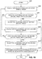
- the example method of FIG. 9 begins at block 900 in which the working machine 100 is being operated (block 900).
- a position as well as an orientation (e.g., an orientation in multiple directions and/or degrees of freedom) of the blade 102 is to be determined to appropriately control the blade 102 via the actuator.
- First and second optical targets are visually measured/captured by the imaging system 610 (block 902).
- an array of shapes of the first and second optical targets are captured by a respective camera (e.g., the cameras 202a, 202b).
- visual location data is selected based on the visual measurements and/or associated confidence indexes (block 904).
- the visual location measurements are selected based on a confidence indexes corresponding to respective cameras.
- the visual location measurements are selected by the example selector 604 from the respective camera with the highest corresponding confidence index.
- the position and/or orientation of the blade 102 is determined based on the selected visual location data (block 906) and the process ends (block 908). Such example determinations of the position and/or orientation of the blade 102 are described below in greater detail in connection with FIGS. 11 and 12 .
- the example method of FIG. 10 begins at block 1000 in which the blade 102 of the working machine 100 is being used at a worksite to grade the worksite (block 1000).
- imaging and/or position/rotation data of the blade 102 is selected between cameras (e.g., between the cameras 202a, 202b) when a criteria/threshold has been met for a camera that is currently selected to provide locational imaging data of the blade 102.
- a camera and/or associated data of the camera is, instead, selected for determining the location/orientation of the blade 102 when a condition has been met such that a criteria or threshold has been met.
- Locational data of a first optical target is visually obtained (block 1002).
- a camera of the illustrated example is used to obtain visual data of the first optical target, which includes an array of shapes arranged in rows.
- block 1004 it is determined whether the locational data of the first optical target meets a criteria (block 1004). If the locational data meets the criteria (block 1004), control of the process proceeds to block 1006, where the locational data of the first optical target is selected for location/orientation determinations of the blade 102 (block 1006) and the process then proceeds to block 1014. Otherwise, the process proceeds to block 1008.
- locational data associated with a second optical target is visually obtained (block 1008).
- imaging data associated with a camera that corresponds to the second optical target is selected and/or obtained.
- the camera is instructed/prompted to provide the locational data.
- the locational data of the second optical target meets a criteria (e.g., whether a calculated confidence index number exceeds a threshold, etc.) (block 1010).
- a criteria e.g., whether a calculated confidence index number exceeds a threshold, etc.
- the criteria associated with the second optical target is identical to the criteria associated with the first optical target. However, in some other examples, the criteria may differ between the first and second optical targets. If the locational data meets the criteria (block 1010), control of the process proceeds to block 1012, where the locational data of the second optical target is then selected (block 1012) and the process proceeds to block 1014. Otherwise, control of the process returns to block 1002.
- a position and rotation of the blade is determined based on the selected locational data (block 1014) and the process ends (block 1016).
- the example method of FIG. 11 begins at block 1100 where an optical target such as the optical target 204 is to be visually captured by the camera 202 to obtain and/or determine translation as well as rotation of the blade 102 (block 1100).
- an image from the camera 202 is obtained or received (block 1102).
- the camera 202 of the illustrated example provides a captured image of the optical target 204 to the imaging system 610.
- Image thresholding is then performed (block 1104).
- image thresholding on the captured image is performed by verifying that the image meets a threshold level of clarity and/or definition.
- the example imaging system 610 may verify that all expected patterns are present in the captured image.
- the image is masked using a previous location (e.g., if the previous location is available) (block 1106).
- the example tracking engine 602 and/or the position/rotation calculator 606 may mask and/or disregard portions of the image based on the previous position/location of the optical target 204 (e.g., based on previously calculated positions of the optical target 204).
- a reduced number of pixels of the captured image are to be used in this analysis, thereby greatly improving the computational efficiency required to analyze the optical target 104.
- segments of the image are then filtered based on size (block 1108).
- objects e.g., identified objects
- a size threshold range e.g., objects that are larger or smaller than a defined threshold range
- Segment contours are then extracted from the captured image (block 1110).
- the position/rotation calculator 606 determines/calculates of segment contours of the example circular targets 402 described above in connection with FIG. 4 based on analyzing the captured image.
- each of the example circular targets 402 is fitted with a corresponding ellipse (e.g., a mathematical expression representing the corresponding ellipse) is generated based on the captured image.
- a corresponding ellipse e.g., a mathematical expression representing the corresponding ellipse
- valid segment(s) are selected based on shape and geometric characteristics (block 1114).
- the circular targets 402 of the optical targets 204 may be analyzed to determine whether they exhibit an appropriate "roundness" and/or circularity.
- centers of respective fitted ellipses are computed for each valid segment by the example position/rotation calculator 606 (block 1116).
- centers of the fitted ellipses are calculated/determined using a calculated area center based on their respective shapes, as represented by the captured image.
- centers are estimated for missing circles (block 1118).
- the centers of a visible portion (e.g., one, two or three, etc.) of the six circular targets 402, for example, are calculated by the example position/rotation calculator 606 based on the captured image while a remaining portion (e.g., not visible portion) of the circular targets 402 are extrapolated/calculated based on the calculated centers (e.g., geometric centers) of the visible portion of the circular targets 402.
- confidence metrics are computed for a current estimation of centers of the circular targets (block 1120).
- a confidence index is calculated by the position/rotation calculator 606 based on determined confidence metrics of each of the circular targets 402.
- a target location and orientation is computed in a camera coordinate system (block 1122).
- the position/rotation calculator 606 utilizes the calculated centers of each of the six circular targets 402 to determine a position and/or rotation of the optical target 204.
- the position and/or rotation of the optical target 204 is used to extrapolate a position and/or rotational displacement (e.g., in multiple degrees of freedom)
- a transformation e.g., a transformation matrix
- the calculated target location and orientation in the camera coordinate system may be converted to a target location and orientation in a vehicle (e.g., working machine) coordinate system.
- the calculated target location and orientation is converted/transformed into a global coordinate system (e.g., a GPS/global coordinate system) or a work site coordinate system (e.g., a local coordinate system).
- an actuator is used to control/displace the blade 102 based on the computed location/orientation.
- FIG. 12 is a flowchart representative of another alternative example method to implement image processing in the examples disclosed herein.
- the example method of FIG. 12 begins at block 1200 in which the circular targets 402 of the optical target 204 are to be used to determine a position/orientation of the optical target 204 and, thus, the blade 102 (block 1200).
- the selector 604 has selected the camera 202 to be used for determining the position and/or rotation of the blade 102.
- a new image is read, captured and/or generated by the camera 202 (block 1202).
- at least one camera 202 generates an image of the optical target 204 when the optical target 204 is within a field of view of the at least one camera 202.
- the captured image includes visual representations/objects of the six circular targets 402, for example.
- the image captured by the camera 202 is undistorted (block 1204).
- numerous imaging filters and/or enhancing techniques may be used to reduce distortion of the captured image and/or effects of environmental distortion (e.g., dust and/or shadows obscuring the captured image of the optical target 204).
- an adaptive threshold technique is applied to the captured image (block 1206).
- the applied adaptive threshold technique may be block-based.
- the captured image is masked using a previous location (block 1208).
- portions of the captured image are masked based on the previous location of the optical target 204 and/or the circular targets 402.
- objects e.g., visible discrete elements
- size block 1210
- objects and/or portions of the captured image may be designated not to be analyzed (e.g., designated to be ignored) based on object size.
- color, a pattern of objects, etc. may be used to filter the objects and/or the portions of the captured image related to the objects.
- contours of remaining objects are calculated (block 1212).
- contours of the circular targets 402 which are objects that are not filtered out of the captured image in block 1210, are determined/captured.
- the example imaging system 610 may capture an outline of the optical target 204 (e.g., the rectangular outer shape of the optical target 204) and uses the outline to generate coordinate clouds and/or mathematical functions representing the outline. Additionally or alternatively, other shapes, reticles and/or indicators (e.g., characters) are captured by the imaging system 610.
- contours of other visual objects e.g., besides the circular targets 402 are determined and/or captured.
- a respective ellipse is fitted (block 1214).
- the imaging system 610 of the illustrated example fits an ellipse and/or a calculated mathematical expression of an ellipse to each detected circular target 402 of the optical target 204.
- the position/rotation calculator 606 may determine whether the ellipses corresponding to each of the circular targets 402 meet a size criteria and/or a shape criteria. Some example constraints/criteria include, but are not limited to, a contour length, a contour area, a difference between major and minor axes of an ellipse, a difference in arear between an ellipse and a contour and/or circularity. Additionally or alternatively, the position/rotation calculator 606 and/or the selector 604 determine whether a correct number of contours (e.g., six for the optical target 204) have been detected in the captured image. If it is determined that the constraints are met (block 1216), control of the process proceeds to block 1218. Otherwise, control of the process returns to block 1214.
- a correct number of contours e.g., six for the optical target 204
- the fiducial centers are located in the image.
- the image is undistorted based on the previously established camera calibration.
- the undistorted image may be made binary with a Sauvola-based adaptive threshold based on pixel blocks.
- size(s) of the blocks may be specified in a parameter file.
- binary objects smaller or larger than a threshold size range e.g., an expected threshold size range
- a threshold size range e.g., an expected threshold size range
- the contours of the remaining objects are computed, and for each contour, an ellipse is fit to contour data points based on a least-squared solution, for example.
- the contours are then filtered by a set of parameters including, but not limited to, contour area, contour length, a difference between a major and a minor axis of the fit ellipse, a difference between an ellipse area and a contour area, and/or circularity of the contour.
- a center is computed based on an average of the ellipse center and/or a center of mass/area/volume of the object. This center may be stored as one of the six fiducial centers, for example. In some examples, once all contours have been analyzed, if six centers are found, center tracking is deemed successful, for example.
- a proper number of centers e.g., six centers
- the position/rotation calculator 606 may be used to determine whether the six fiducial centers have been imaged by the camera 202 or calculated/determined based on the captured image from the camera 202. If the proper number of calculated centers have been determined (block 1220), control of the process proceeds to block 1222. Otherwise, control of the process returns to block 1202.
- the calculated centers of the illustrated example are sorted by location (block 1222).
- the fiducial centers are of the circular targets 402 are sorted by location that correspond with real-world fiducial center points.
- the fiducial center coordinates are also shifted based on a center of a camera reference frame.
- a transformation (e.g., a transforming array) is calculated from a camera reference frame to a marker reference frame (block 1224).
- a geometric transformation between a camera reference frame and a fiducial reference frame is computed/determined by the position/rotation calculator 606.
- the computation may use camera calibration parameters to account for radial and tangential lens distortion in conjunction with a homography, which is a linear map from one projective reference frame to another and defined by a relationship between image points and real-world points, for example.
- This portion of the example method may be similar to example method for calibration of the camera described above in connection with FIGS. 5A and 5B , in which a three-dimensional rotation and translation is calculated such that a matrix transformation from the real-world reference frame to the camera reference frame is defined.
- the arbitrary scale factor can be removed by normalizing the resulting pixel location (through dividing x i and y i by s ).
- the difference between the pixel center points and the corresponding re-projected center points is computed and if the largest re-projection error is less than three pixels, for example, the transformation is deemed to be sufficiently accurate and is, thus, stored and control of the process proceeds to block 1228. If the errors of the re-projected center points are not smaller than the threshold (block 1226), control of the process returns to block 1202.
- the transformation is saved/stored (block 1228).
- a location of the blade 102 is determined/calculated and projected onto the captured image (block 1230).
- a mask is created based on the current determined location of the circular targets 402 and/or the optical target 204 (block 1232).
- a next image e.g., during an additional analysis cycle of the target 204
- a previous fiducial location is taken into account when searching for a next fiducial.
- a mask may be placed onto the current capture image before thresholding that will "black out" pixel data outside of a region of interest.
- a size of the mask is determined by a size of the previous fiducial in the image such that the fiducial that is further away from the mask will be relatively smaller.
- the example method of FIG. 12 will not use a mask and will search/analyze the entire captured image instead.
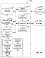
- FIG. 13 is a block diagram of an example processor platform 1300 capable of executing the instructions of FIGS. 9-12 to implement the displacement detection analysis system 600 of FIG.6 .
- the processor platform 1300 can be, for example, a server, a personal computer, a mobile device (e.g., a cell phone, a smart phone, a tablet such as an iPadTM), a personal digital assistant (PDA), an Internet appliance, a digital video recorder, a set top box, or any other type of computing device.
- a mobile device e.g., a cell phone, a smart phone, a tablet such as an iPadTM
- PDA personal digital assistant
- Internet appliance e.g., a digital video recorder, a set top box, or any other type of computing device.
- the processor platform 1300 of the illustrated example includes a processor 1312.
- the processor 1312 of the illustrated example is hardware.
- the processor 1312 can be implemented by one or more integrated circuits, logic circuits, microprocessors or controllers from any desired family or manufacturer.
- the processor 1312 of the illustrated example includes a local memory 1313 (e.g., a cache).
- the processor 1312 also includes the example tracking engine 602, the example selector 604, the example actuator system 608 and/or the example imaging system 610.
- the processor 1312 of the illustrated example is in communication with a main memory including a volatile memory 1314 and a non-volatile memory 1316 via a bus 1318.
- the volatile memory 1314 may be implemented by Synchronous Dynamic Random Access Memory (SDRAM), Dynamic Random Access Memory (DRAM), RAMBUS Dynamic Random Access Memory (RDRAM) and/or any other type of random access memory device.
- the non-volatile memory 1316 may be implemented by flash memory and/or any other desired type of memory device. Access to the main memory 1314, 1316 is controlled by a memory controller.
- the processor platform 1300 of the illustrated example also includes an interface circuit 1320.
- the interface circuit 1320 may be implemented by any type of interface standard, such as an Ethernet interface, a universal serial bus (USB), and/or a PCI express interface.
- one or more input devices 1322 are connected to the interface circuit 1320.
- the input device(s) 1322 permit(s) a user to enter data and commands into the processor 1312.
- the input device(s) can be implemented by, for example, an audio sensor, a microphone, a camera (still or video), a keyboard, a button, a mouse, a touchscreen, a track-pad, a trackball, isopoint and/or a voice recognition system.
- One or more output devices 1324 are also connected to the interface circuit 1320 of the illustrated example.
- the output devices 1324 can be implemented, for example, by display devices (e.g., a light emitting diode (LED), an organic light emitting diode (OLED), a liquid crystal display, a cathode ray tube display (CRT), a touchscreen, a tactile output device, a printer and/or speakers).
- the interface circuit 1320 of the illustrated example thus, typically includes a graphics driver card, a graphics driver chip or a graphics driver processor.
- the interface circuit 1320 of the illustrated example also includes a communication device such as a transmitter, a receiver, a transceiver, a modem and/or network interface card to facilitate exchange of data with external machines (e.g., computing devices of any kind) via a network 1326 (e.g., an Ethernet connection, a digital subscriber line (DSL), a telephone line, coaxial cable, a cellular telephone system, etc.).
- a communication device such as a transmitter, a receiver, a transceiver, a modem and/or network interface card to facilitate exchange of data with external machines (e.g., computing devices of any kind) via a network 1326 (e.g., an Ethernet connection, a digital subscriber line (DSL), a telephone line, coaxial cable, a cellular telephone system, etc.).
- DSL digital subscriber line
- the processor platform 1300 of the illustrated example also includes one or more mass storage devices 1328 for storing software and/or data.
- mass storage devices 1328 include floppy disk drives, hard drive disks, compact disk drives, Blu-ray disk drives, RAID systems, and digital versatile disk (DVD) drives.
- the coded instructions 1332 of FIGS. 9-12 may be stored in the mass storage device 1328, in the volatile memory 1314, in the non-volatile memory 1316, and/or on a removable tangible computer readable storage medium such as a CD or DVD.
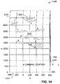
- FIG. 14 an example graph 1400 that is representative of accuracy of the examples disclosed herein is shown.
- the example graph 1400 depicts a verification of the accuracy of the examples disclosed herein.
- axes 1402, 1404, 1405 represent coordinate positions of three orthogonal directions, which are denoted as "X,” "Y” and "Z,” respectively.
- contours 1406 represent three-dimensional error ranges of multiple fiducial centers (i.e., fiducial centers 1-10).
- error ranges of all ten of the fiducial centers were determined to be within approximately 3-10 mm while a blade to which the fiducial centers were coupled to include a size of several meters/feet.
- conventional systems offer an accuracy of approximately 30 mm.
- the above disclosed methods and apparatus enable a cost-effective solution to accurately track/monitor a position and/or orientation of a blade or other working implement of a vehicle (e.g., a working machine).
- a vehicle e.g., a working machine
- the examples disclosed herein provide accurate positional/rotational tracking of a working implement that can be performed in a very quick and efficient (e.g., computationally efficient) manner being highly cost-effective.
Landscapes
- Engineering & Computer Science (AREA)
- Mining & Mineral Resources (AREA)
- Civil Engineering (AREA)
- General Engineering & Computer Science (AREA)
- Structural Engineering (AREA)
- Physics & Mathematics (AREA)
- Mechanical Engineering (AREA)
- General Physics & Mathematics (AREA)
- Optics & Photonics (AREA)
- Acoustics & Sound (AREA)
- Electromagnetism (AREA)
- Computer Vision & Pattern Recognition (AREA)
- Theoretical Computer Science (AREA)
- Remote Sensing (AREA)
- Radar, Positioning & Navigation (AREA)
- Multimedia (AREA)
- Signal Processing (AREA)
- Length Measuring Devices By Optical Means (AREA)
Applications Claiming Priority (1)
| Application Number | Priority Date | Filing Date | Title |
|---|---|---|---|
| US15/253,256 US10634492B2 (en) | 2016-08-31 | 2016-08-31 | Methods and apparatus to track a blade |
Publications (2)
| Publication Number | Publication Date |
|---|---|
| EP3290592A1 true EP3290592A1 (de) | 2018-03-07 |
| EP3290592B1 EP3290592B1 (de) | 2023-12-27 |
Family
ID=59966553
Family Applications (1)
| Application Number | Title | Priority Date | Filing Date |
|---|---|---|---|
| EP17188896.9A Active EP3290592B1 (de) | 2016-08-31 | 2017-08-31 | Verfahren und vorrichtung zur verfolgung einer klinge |
Country Status (2)
| Country | Link |
|---|---|
| US (2) | US10634492B2 (de) |
| EP (1) | EP3290592B1 (de) |
Cited By (2)
| Publication number | Priority date | Publication date | Assignee | Title |
|---|---|---|---|---|
| RU2765070C2 (ru) * | 2019-01-17 | 2022-01-25 | Дир Энд Компани | Использование вида с верхней точки для калибровки блока регулирования уклона |
| US11976444B2 (en) | 2021-12-03 | 2024-05-07 | Deere & Company | Work machine with grade control using external field of view system and method |
Families Citing this family (18)
| Publication number | Priority date | Publication date | Assignee | Title |
|---|---|---|---|---|
| JP6850078B2 (ja) * | 2016-03-23 | 2021-03-31 | 株式会社小松製作所 | モータグレーダ |
| US10975552B2 (en) * | 2016-09-16 | 2021-04-13 | Komatsu Ltd. | Control system and method for work vehicle |
| US10526766B2 (en) * | 2017-07-31 | 2020-01-07 | Deere & Company | Work machines and methods and systems to control and determine a position of an associated implement |
| US11891284B2 (en) * | 2018-03-28 | 2024-02-06 | The Heil Co. | Camera safety system for aerial device |
| JP7166088B2 (ja) * | 2018-06-28 | 2022-11-07 | 株式会社小松製作所 | 作業車両による作業を判定するためのシステム、方法、及び学習済みモデルの製造方法 |
| US11142890B2 (en) | 2018-08-08 | 2021-10-12 | Deere & Company | System and method of soil management for an implement |
| US10883248B2 (en) | 2018-10-22 | 2021-01-05 | Deere & Company | Road maintenance using stored maintenance passes |
| CN111291585B (zh) * | 2018-12-06 | 2023-12-08 | 杭州海康威视数字技术股份有限公司 | 一种基于gps的目标跟踪系统、方法、装置及球机 |
| US11702818B2 (en) | 2019-05-15 | 2023-07-18 | Deere & Company | Motor grader cutting edge wear calibration and warning system |
| US11686067B2 (en) | 2019-05-15 | 2023-06-27 | Deere & Company | Motor grader cutting edge wear calibration and warning system |
| JP7624291B2 (ja) * | 2019-05-31 | 2025-01-30 | 株式会社小松製作所 | マップ生成システム及びマップ生成方法 |
| US11193255B2 (en) | 2019-07-31 | 2021-12-07 | Deere & Company | System and method for maximizing productivity of a work vehicle |
| JP7409074B2 (ja) * | 2019-12-25 | 2024-01-09 | コベルコ建機株式会社 | 作業支援サーバ、撮像装置の選択方法 |
| US11429114B2 (en) | 2020-02-14 | 2022-08-30 | Deere & Company | Implement control of vehicle and implement combination |
| US11692319B2 (en) | 2020-03-25 | 2023-07-04 | Caterpillar Paving Products Inc. | Dynamic image augmentation for milling machine |
| US12366860B2 (en) * | 2020-12-11 | 2025-07-22 | Raven Industries, Inc. | Sensor fusion in agricultural vehicle steering |
| CN114088062B (zh) * | 2021-02-24 | 2024-03-22 | 上海商汤临港智能科技有限公司 | 目标定位方法及装置、电子设备和存储介质 |
| US12460376B2 (en) | 2023-02-28 | 2025-11-04 | Deere & Company | Elevation increment-decrement with slope control |
Citations (6)
| Publication number | Priority date | Publication date | Assignee | Title |
|---|---|---|---|---|
| EP2150772A1 (de) * | 2007-04-18 | 2010-02-10 | Snap-on Incorporated | Verfahren zur verwendung mit einem optischen ausrichtsystem zum positionieren einer ausstattung relativ zu einem fahrzeug |
| US20100121540A1 (en) * | 2008-11-12 | 2010-05-13 | Kabushiki Kaisha Topcon | Industrial machine |
| US20110169949A1 (en) * | 2010-01-12 | 2011-07-14 | Topcon Positioning Systems, Inc. | System and Method for Orienting an Implement on a Vehicle |
| US20150106004A1 (en) * | 2004-08-26 | 2015-04-16 | Trimble Navigation Limited | Auto recognition of at least one standoff target to determine position information for a mobile machine |
| US20150178320A1 (en) * | 2013-12-20 | 2015-06-25 | Qualcomm Incorporated | Systems, methods, and apparatus for image retrieval |
| US20150225923A1 (en) * | 2014-02-13 | 2015-08-13 | Trimble Navigation Limited | Non-contact location and orientation determination of an implement coupled with a mobile machine |
Family Cites Families (6)
| Publication number | Priority date | Publication date | Assignee | Title |
|---|---|---|---|---|
| US5724743A (en) * | 1992-09-04 | 1998-03-10 | Snap-On Technologies, Inc. | Method and apparatus for determining the alignment of motor vehicle wheels |
| US6736216B2 (en) | 2000-05-05 | 2004-05-18 | Leica Geosystems Gr, Llc | Laser-guided construction equipment |
| EP2232463B1 (de) * | 2007-11-30 | 2018-04-11 | Searidge Technologies INC. | Flughafen-zielverfolgungssystem |
| US9124780B2 (en) | 2010-09-17 | 2015-09-01 | Certusview Technologies, Llc | Methods and apparatus for tracking motion and/or orientation of a marking device |
| US8843279B2 (en) | 2011-06-06 | 2014-09-23 | Motion Metrics International Corp. | Method and apparatus for determining a spatial positioning of loading equipment |
| US8972119B2 (en) | 2013-03-15 | 2015-03-03 | Novatel Inc. | System and method for heavy equipment navigation and working edge positioning |
-
2016
- 2016-08-31 US US15/253,256 patent/US10634492B2/en active Active
-
2017
- 2017-08-31 EP EP17188896.9A patent/EP3290592B1/de active Active
-
2020
- 2020-03-19 US US16/824,287 patent/US11105624B2/en active Active
Patent Citations (6)
| Publication number | Priority date | Publication date | Assignee | Title |
|---|---|---|---|---|
| US20150106004A1 (en) * | 2004-08-26 | 2015-04-16 | Trimble Navigation Limited | Auto recognition of at least one standoff target to determine position information for a mobile machine |
| EP2150772A1 (de) * | 2007-04-18 | 2010-02-10 | Snap-on Incorporated | Verfahren zur verwendung mit einem optischen ausrichtsystem zum positionieren einer ausstattung relativ zu einem fahrzeug |
| US20100121540A1 (en) * | 2008-11-12 | 2010-05-13 | Kabushiki Kaisha Topcon | Industrial machine |
| US20110169949A1 (en) * | 2010-01-12 | 2011-07-14 | Topcon Positioning Systems, Inc. | System and Method for Orienting an Implement on a Vehicle |
| US20150178320A1 (en) * | 2013-12-20 | 2015-06-25 | Qualcomm Incorporated | Systems, methods, and apparatus for image retrieval |
| US20150225923A1 (en) * | 2014-02-13 | 2015-08-13 | Trimble Navigation Limited | Non-contact location and orientation determination of an implement coupled with a mobile machine |
Cited By (2)
| Publication number | Priority date | Publication date | Assignee | Title |
|---|---|---|---|---|
| RU2765070C2 (ru) * | 2019-01-17 | 2022-01-25 | Дир Энд Компани | Использование вида с верхней точки для калибровки блока регулирования уклона |
| US11976444B2 (en) | 2021-12-03 | 2024-05-07 | Deere & Company | Work machine with grade control using external field of view system and method |
Also Published As
| Publication number | Publication date |
|---|---|
| US20200217660A1 (en) | 2020-07-09 |
| US20180061040A1 (en) | 2018-03-01 |
| EP3290592B1 (de) | 2023-12-27 |
| US10634492B2 (en) | 2020-04-28 |
| US11105624B2 (en) | 2021-08-31 |
Similar Documents
| Publication | Publication Date | Title |
|---|---|---|
| US11105624B2 (en) | Methods and apparatus to track a blade | |
| CN107738612B (zh) | 基于全景视觉辅助系统的自动泊车停车位检测与识别系统 | |
| CN106469448B (zh) | 利用3d视觉进行自动化工业检查 | |
| EP3943880B1 (de) | Artikeldetektionsvorrichtung, artikeldetektionsverfahren und industriefahrzeug | |
| CN111627072A (zh) | 一种对多传感器进行标定的方法、装置和存储介质 | |
| CN110766758B (zh) | 标定方法、装置、系统及存储装置 | |
| US20150178956A1 (en) | Apparatus, systems, and methods for processing a height map | |
| CN101539422B (zh) | 一种单目视觉实时测距方法 | |
| US20100303336A1 (en) | Method for ascertaining the axis of rotation of a vehicle wheel | |
| US9239232B2 (en) | Method and system for determining position and orientation of a measuring instrument | |
| EP4396779B1 (de) | Verfahren und systeme zur erzeugung von kameramodellen zur kamerakalibrierung | |
| EP2551633B1 (de) | Dreidimensionale abstandsmessvorrichtung und verfahren dafür | |
| CN113538583B (zh) | 一种工件在机床上位置的精准定位方法及视觉系统 | |
| CN108007388A (zh) | 一种基于机器视觉的转盘角度高精度在线测量方法 | |
| CN101294801A (zh) | 基于双目视觉的车距测量方法 | |
| CN112486207A (zh) | 一种基于视觉识别的无人机自主降落方法 | |
| CN104792312A (zh) | 以定距三球为视觉标志物的室内自动运输车定位系统 | |
| JP2006252473A (ja) | 障害物検出装置、キャリブレーション装置、キャリブレーション方法およびキャリブレーションプログラム | |
| CN110675341B (zh) | 一种单目光视觉引导的水下机器人与海底平台对接方法 | |
| CN107895344B (zh) | 视频拼接装置及方法 | |
| KR101030317B1 (ko) | 스테레오 비전을 이용하여 장애물을 추적하는 장치 및 방법 | |
| JP2015184929A (ja) | 立体物検出装置、立体物検出方法、および立体物検出プログラム | |
| CN111174722A (zh) | 一种三维轮廓重建方法及装置 | |
| WO2022239355A1 (ja) | 位置測定システム | |
| CN120630228A (zh) | 一种多传感器融合的船舱装卸设备协同定位方法及系统 |
Legal Events
| Date | Code | Title | Description |
|---|---|---|---|
| PUAI | Public reference made under article 153(3) epc to a published international application that has entered the european phase |
Free format text: ORIGINAL CODE: 0009012 |
|
| STAA | Information on the status of an ep patent application or granted ep patent |
Free format text: STATUS: THE APPLICATION HAS BEEN PUBLISHED |
|
| AK | Designated contracting states |
Kind code of ref document: A1 Designated state(s): AL AT BE BG CH CY CZ DE DK EE ES FI FR GB GR HR HU IE IS IT LI LT LU LV MC MK MT NL NO PL PT RO RS SE SI SK SM TR |
|
| AX | Request for extension of the european patent |
Extension state: BA ME |
|
| STAA | Information on the status of an ep patent application or granted ep patent |
Free format text: STATUS: REQUEST FOR EXAMINATION WAS MADE |
|
| 17P | Request for examination filed |
Effective date: 20180907 |
|
| RBV | Designated contracting states (corrected) |
Designated state(s): AL AT BE BG CH CY CZ DE DK EE ES FI FR GB GR HR HU IE IS IT LI LT LU LV MC MK MT NL NO PL PT RO RS SE SI SK SM TR |
|
| STAA | Information on the status of an ep patent application or granted ep patent |
Free format text: STATUS: EXAMINATION IS IN PROGRESS |
|
| 17Q | First examination report despatched |
Effective date: 20190704 |
|
| GRAP | Despatch of communication of intention to grant a patent |
Free format text: ORIGINAL CODE: EPIDOSNIGR1 |
|
| STAA | Information on the status of an ep patent application or granted ep patent |
Free format text: STATUS: GRANT OF PATENT IS INTENDED |
|
| INTG | Intention to grant announced |
Effective date: 20230804 |
|
| RIN1 | Information on inventor provided before grant (corrected) |
Inventor name: DAVIS, TRAVIS Inventor name: KISE, MICHIO Inventor name: RICH, SHAYNE Inventor name: BORGSTADT, JUSTIN Inventor name: LOUKILI, TARIK Inventor name: BEERY, SARA |
|
| GRAS | Grant fee paid |
Free format text: ORIGINAL CODE: EPIDOSNIGR3 |
|
| GRAA | (expected) grant |
Free format text: ORIGINAL CODE: 0009210 |
|
| STAA | Information on the status of an ep patent application or granted ep patent |
Free format text: STATUS: THE PATENT HAS BEEN GRANTED |
|
| AK | Designated contracting states |
Kind code of ref document: B1 Designated state(s): AL AT BE BG CH CY CZ DE DK EE ES FI FR GB GR HR HU IE IS IT LI LT LU LV MC MK MT NL NO PL PT RO RS SE SI SK SM TR |
|
| REG | Reference to a national code |
Ref country code: GB Ref legal event code: FG4D |
|
| REG | Reference to a national code |
Ref country code: CH Ref legal event code: EP |
|
| REG | Reference to a national code |
Ref country code: DE Ref legal event code: R096 Ref document number: 602017077859 Country of ref document: DE |
|
| REG | Reference to a national code |
Ref country code: IE Ref legal event code: FG4D |
|
| PG25 | Lapsed in a contracting state [announced via postgrant information from national office to epo] |
Ref country code: GR Free format text: LAPSE BECAUSE OF FAILURE TO SUBMIT A TRANSLATION OF THE DESCRIPTION OR TO PAY THE FEE WITHIN THE PRESCRIBED TIME-LIMIT Effective date: 20240328 |
|
| REG | Reference to a national code |
Ref country code: LT Ref legal event code: MG9D |
|
| PG25 | Lapsed in a contracting state [announced via postgrant information from national office to epo] |
Ref country code: LT Free format text: LAPSE BECAUSE OF FAILURE TO SUBMIT A TRANSLATION OF THE DESCRIPTION OR TO PAY THE FEE WITHIN THE PRESCRIBED TIME-LIMIT Effective date: 20231227 |
|
| PG25 | Lapsed in a contracting state [announced via postgrant information from national office to epo] |
Ref country code: ES Free format text: LAPSE BECAUSE OF FAILURE TO SUBMIT A TRANSLATION OF THE DESCRIPTION OR TO PAY THE FEE WITHIN THE PRESCRIBED TIME-LIMIT Effective date: 20231227 |
|
| PG25 | Lapsed in a contracting state [announced via postgrant information from national office to epo] |
Ref country code: LT Free format text: LAPSE BECAUSE OF FAILURE TO SUBMIT A TRANSLATION OF THE DESCRIPTION OR TO PAY THE FEE WITHIN THE PRESCRIBED TIME-LIMIT Effective date: 20231227 Ref country code: GR Free format text: LAPSE BECAUSE OF FAILURE TO SUBMIT A TRANSLATION OF THE DESCRIPTION OR TO PAY THE FEE WITHIN THE PRESCRIBED TIME-LIMIT Effective date: 20240328 Ref country code: FI Free format text: LAPSE BECAUSE OF FAILURE TO SUBMIT A TRANSLATION OF THE DESCRIPTION OR TO PAY THE FEE WITHIN THE PRESCRIBED TIME-LIMIT Effective date: 20231227 Ref country code: ES Free format text: LAPSE BECAUSE OF FAILURE TO SUBMIT A TRANSLATION OF THE DESCRIPTION OR TO PAY THE FEE WITHIN THE PRESCRIBED TIME-LIMIT Effective date: 20231227 Ref country code: BG Free format text: LAPSE BECAUSE OF FAILURE TO SUBMIT A TRANSLATION OF THE DESCRIPTION OR TO PAY THE FEE WITHIN THE PRESCRIBED TIME-LIMIT Effective date: 20240327 |
|
| REG | Reference to a national code |
Ref country code: NL Ref legal event code: MP Effective date: 20231227 |
|
| REG | Reference to a national code |
Ref country code: AT Ref legal event code: MK05 Ref document number: 1644619 Country of ref document: AT Kind code of ref document: T Effective date: 20231227 |
|
| PG25 | Lapsed in a contracting state [announced via postgrant information from national office to epo] |
Ref country code: NL Free format text: LAPSE BECAUSE OF FAILURE TO SUBMIT A TRANSLATION OF THE DESCRIPTION OR TO PAY THE FEE WITHIN THE PRESCRIBED TIME-LIMIT Effective date: 20231227 |
|
| PG25 | Lapsed in a contracting state [announced via postgrant information from national office to epo] |
Ref country code: SE Free format text: LAPSE BECAUSE OF FAILURE TO SUBMIT A TRANSLATION OF THE DESCRIPTION OR TO PAY THE FEE WITHIN THE PRESCRIBED TIME-LIMIT Effective date: 20231227 Ref country code: RS Free format text: LAPSE BECAUSE OF FAILURE TO SUBMIT A TRANSLATION OF THE DESCRIPTION OR TO PAY THE FEE WITHIN THE PRESCRIBED TIME-LIMIT Effective date: 20231227 Ref country code: NO Free format text: LAPSE BECAUSE OF FAILURE TO SUBMIT A TRANSLATION OF THE DESCRIPTION OR TO PAY THE FEE WITHIN THE PRESCRIBED TIME-LIMIT Effective date: 20240327 Ref country code: NL Free format text: LAPSE BECAUSE OF FAILURE TO SUBMIT A TRANSLATION OF THE DESCRIPTION OR TO PAY THE FEE WITHIN THE PRESCRIBED TIME-LIMIT Effective date: 20231227 Ref country code: LV Free format text: LAPSE BECAUSE OF FAILURE TO SUBMIT A TRANSLATION OF THE DESCRIPTION OR TO PAY THE FEE WITHIN THE PRESCRIBED TIME-LIMIT Effective date: 20231227 Ref country code: HR Free format text: LAPSE BECAUSE OF FAILURE TO SUBMIT A TRANSLATION OF THE DESCRIPTION OR TO PAY THE FEE WITHIN THE PRESCRIBED TIME-LIMIT Effective date: 20231227 |
|
| PG25 | Lapsed in a contracting state [announced via postgrant information from national office to epo] |
Ref country code: IS Free format text: LAPSE BECAUSE OF FAILURE TO SUBMIT A TRANSLATION OF THE DESCRIPTION OR TO PAY THE FEE WITHIN THE PRESCRIBED TIME-LIMIT Effective date: 20240427 |
|
| PG25 | Lapsed in a contracting state [announced via postgrant information from national office to epo] |
Ref country code: AT Free format text: LAPSE BECAUSE OF FAILURE TO SUBMIT A TRANSLATION OF THE DESCRIPTION OR TO PAY THE FEE WITHIN THE PRESCRIBED TIME-LIMIT Effective date: 20231227 Ref country code: CZ Free format text: LAPSE BECAUSE OF FAILURE TO SUBMIT A TRANSLATION OF THE DESCRIPTION OR TO PAY THE FEE WITHIN THE PRESCRIBED TIME-LIMIT Effective date: 20231227 |
|
| PG25 | Lapsed in a contracting state [announced via postgrant information from national office to epo] |
Ref country code: SK Free format text: LAPSE BECAUSE OF FAILURE TO SUBMIT A TRANSLATION OF THE DESCRIPTION OR TO PAY THE FEE WITHIN THE PRESCRIBED TIME-LIMIT Effective date: 20231227 |
|
| PG25 | Lapsed in a contracting state [announced via postgrant information from national office to epo] |
Ref country code: SM Free format text: LAPSE BECAUSE OF FAILURE TO SUBMIT A TRANSLATION OF THE DESCRIPTION OR TO PAY THE FEE WITHIN THE PRESCRIBED TIME-LIMIT Effective date: 20231227 Ref country code: SK Free format text: LAPSE BECAUSE OF FAILURE TO SUBMIT A TRANSLATION OF THE DESCRIPTION OR TO PAY THE FEE WITHIN THE PRESCRIBED TIME-LIMIT Effective date: 20231227 Ref country code: RO Free format text: LAPSE BECAUSE OF FAILURE TO SUBMIT A TRANSLATION OF THE DESCRIPTION OR TO PAY THE FEE WITHIN THE PRESCRIBED TIME-LIMIT Effective date: 20231227 Ref country code: IT Free format text: LAPSE BECAUSE OF FAILURE TO SUBMIT A TRANSLATION OF THE DESCRIPTION OR TO PAY THE FEE WITHIN THE PRESCRIBED TIME-LIMIT Effective date: 20231227 Ref country code: IS Free format text: LAPSE BECAUSE OF FAILURE TO SUBMIT A TRANSLATION OF THE DESCRIPTION OR TO PAY THE FEE WITHIN THE PRESCRIBED TIME-LIMIT Effective date: 20240427 Ref country code: EE Free format text: LAPSE BECAUSE OF FAILURE TO SUBMIT A TRANSLATION OF THE DESCRIPTION OR TO PAY THE FEE WITHIN THE PRESCRIBED TIME-LIMIT Effective date: 20231227 Ref country code: CZ Free format text: LAPSE BECAUSE OF FAILURE TO SUBMIT A TRANSLATION OF THE DESCRIPTION OR TO PAY THE FEE WITHIN THE PRESCRIBED TIME-LIMIT Effective date: 20231227 Ref country code: AT Free format text: LAPSE BECAUSE OF FAILURE TO SUBMIT A TRANSLATION OF THE DESCRIPTION OR TO PAY THE FEE WITHIN THE PRESCRIBED TIME-LIMIT Effective date: 20231227 |
|
| PG25 | Lapsed in a contracting state [announced via postgrant information from national office to epo] |
Ref country code: PT Free format text: LAPSE BECAUSE OF FAILURE TO SUBMIT A TRANSLATION OF THE DESCRIPTION OR TO PAY THE FEE WITHIN THE PRESCRIBED TIME-LIMIT Effective date: 20240429 Ref country code: PL Free format text: LAPSE BECAUSE OF FAILURE TO SUBMIT A TRANSLATION OF THE DESCRIPTION OR TO PAY THE FEE WITHIN THE PRESCRIBED TIME-LIMIT Effective date: 20231227 |
|
| REG | Reference to a national code |
Ref country code: DE Ref legal event code: R097 Ref document number: 602017077859 Country of ref document: DE |
|
| PG25 | Lapsed in a contracting state [announced via postgrant information from national office to epo] |
Ref country code: DK Free format text: LAPSE BECAUSE OF FAILURE TO SUBMIT A TRANSLATION OF THE DESCRIPTION OR TO PAY THE FEE WITHIN THE PRESCRIBED TIME-LIMIT Effective date: 20231227 |
|
| PG25 | Lapsed in a contracting state [announced via postgrant information from national office to epo] |
Ref country code: DK Free format text: LAPSE BECAUSE OF FAILURE TO SUBMIT A TRANSLATION OF THE DESCRIPTION OR TO PAY THE FEE WITHIN THE PRESCRIBED TIME-LIMIT Effective date: 20231227 |
|
| PLBE | No opposition filed within time limit |
Free format text: ORIGINAL CODE: 0009261 |
|
| STAA | Information on the status of an ep patent application or granted ep patent |
Free format text: STATUS: NO OPPOSITION FILED WITHIN TIME LIMIT |
|
| 26N | No opposition filed |
Effective date: 20240930 |
|
| REG | Reference to a national code |
Ref country code: CH Ref legal event code: PL |
|
| PG25 | Lapsed in a contracting state [announced via postgrant information from national office to epo] |
Ref country code: LU Free format text: LAPSE BECAUSE OF NON-PAYMENT OF DUE FEES Effective date: 20240831 |
|
| PG25 | Lapsed in a contracting state [announced via postgrant information from national office to epo] |
Ref country code: CH Free format text: LAPSE BECAUSE OF NON-PAYMENT OF DUE FEES Effective date: 20240831 Ref country code: SI Free format text: LAPSE BECAUSE OF FAILURE TO SUBMIT A TRANSLATION OF THE DESCRIPTION OR TO PAY THE FEE WITHIN THE PRESCRIBED TIME-LIMIT Effective date: 20231227 Ref country code: MC Free format text: LAPSE BECAUSE OF FAILURE TO SUBMIT A TRANSLATION OF THE DESCRIPTION OR TO PAY THE FEE WITHIN THE PRESCRIBED TIME-LIMIT Effective date: 20231227 |
|
| REG | Reference to a national code |
Ref country code: BE Ref legal event code: MM Effective date: 20240831 |
|
| PG25 | Lapsed in a contracting state [announced via postgrant information from national office to epo] |
Ref country code: BE Free format text: LAPSE BECAUSE OF NON-PAYMENT OF DUE FEES Effective date: 20240831 |
|
| PG25 | Lapsed in a contracting state [announced via postgrant information from national office to epo] |
Ref country code: IE Free format text: LAPSE BECAUSE OF NON-PAYMENT OF DUE FEES Effective date: 20240831 |
|
| PGFP | Annual fee paid to national office [announced via postgrant information from national office to epo] |
Ref country code: DE Payment date: 20250721 Year of fee payment: 9 |
|
| PGFP | Annual fee paid to national office [announced via postgrant information from national office to epo] |
Ref country code: GB Payment date: 20250827 Year of fee payment: 9 |
|
| PGFP | Annual fee paid to national office [announced via postgrant information from national office to epo] |
Ref country code: FR Payment date: 20250825 Year of fee payment: 9 |
|
| PG25 | Lapsed in a contracting state [announced via postgrant information from national office to epo] |
Ref country code: CY Free format text: LAPSE BECAUSE OF FAILURE TO SUBMIT A TRANSLATION OF THE DESCRIPTION OR TO PAY THE FEE WITHIN THE PRESCRIBED TIME-LIMIT; INVALID AB INITIO Effective date: 20170831 |
|
| PG25 | Lapsed in a contracting state [announced via postgrant information from national office to epo] |
Ref country code: HU Free format text: LAPSE BECAUSE OF FAILURE TO SUBMIT A TRANSLATION OF THE DESCRIPTION OR TO PAY THE FEE WITHIN THE PRESCRIBED TIME-LIMIT; INVALID AB INITIO Effective date: 20170831 |