EP3290340B1 - Lateral linear moving curtain rail - Google Patents
Lateral linear moving curtain rail Download PDFInfo
- Publication number
- EP3290340B1 EP3290340B1 EP16186258.6A EP16186258A EP3290340B1 EP 3290340 B1 EP3290340 B1 EP 3290340B1 EP 16186258 A EP16186258 A EP 16186258A EP 3290340 B1 EP3290340 B1 EP 3290340B1
- Authority
- EP
- European Patent Office
- Prior art keywords
- rail
- movable
- guiding
- curtain rail
- curtain
- Prior art date
- Legal status (The legal status is an assumption and is not a legal conclusion. Google has not performed a legal analysis and makes no representation as to the accuracy of the status listed.)
- Active
Links
- 238000010168 coupling process Methods 0.000 claims description 29
- 238000005859 coupling reaction Methods 0.000 claims description 29
- 230000000717 retained effect Effects 0.000 claims description 3
- 229920005372 Plexiglas® Polymers 0.000 description 14
- 238000012423 maintenance Methods 0.000 description 14
- VVQNEPGJFQJSBK-UHFFFAOYSA-N Methyl methacrylate Chemical compound COC(=O)C(C)=C VVQNEPGJFQJSBK-UHFFFAOYSA-N 0.000 description 13
- 230000000694 effects Effects 0.000 description 4
- 230000008878 coupling Effects 0.000 description 2
- 230000010006 flight Effects 0.000 description 2
- 230000007704 transition Effects 0.000 description 2
- QVGXLLKOCUKJST-UHFFFAOYSA-N atomic oxygen Chemical compound [O] QVGXLLKOCUKJST-UHFFFAOYSA-N 0.000 description 1
- 230000001419 dependent effect Effects 0.000 description 1
- 230000000763 evoking effect Effects 0.000 description 1
- 238000009434 installation Methods 0.000 description 1
- 230000033001 locomotion Effects 0.000 description 1
- 229910052760 oxygen Inorganic materials 0.000 description 1
- 239000001301 oxygen Substances 0.000 description 1
- 238000005192 partition Methods 0.000 description 1
- 239000004926 polymethyl methacrylate Substances 0.000 description 1
- 230000000284 resting effect Effects 0.000 description 1
- 238000000638 solvent extraction Methods 0.000 description 1
Images


Classifications
-
- B—PERFORMING OPERATIONS; TRANSPORTING
- B64—AIRCRAFT; AVIATION; COSMONAUTICS
- B64D—EQUIPMENT FOR FITTING IN OR TO AIRCRAFT; FLIGHT SUITS; PARACHUTES; ARRANGEMENTS OR MOUNTING OF POWER PLANTS OR PROPULSION TRANSMISSIONS IN AIRCRAFT
- B64D11/00—Passenger or crew accommodation; Flight-deck installations not otherwise provided for
- B64D11/0023—Movable or removable cabin dividers, e.g. for class separation
-
- A—HUMAN NECESSITIES
- A47—FURNITURE; DOMESTIC ARTICLES OR APPLIANCES; COFFEE MILLS; SPICE MILLS; SUCTION CLEANERS IN GENERAL
- A47H—FURNISHINGS FOR WINDOWS OR DOORS
- A47H1/00—Curtain suspension devices
- A47H1/04—Curtain rails
- A47H1/06—Curtain rails fixed
-
- A—HUMAN NECESSITIES
- A47—FURNITURE; DOMESTIC ARTICLES OR APPLIANCES; COFFEE MILLS; SPICE MILLS; SUCTION CLEANERS IN GENERAL
- A47H—FURNISHINGS FOR WINDOWS OR DOORS
- A47H1/00—Curtain suspension devices
- A47H1/04—Curtain rails
- A47H2001/045—Curtain rails being curved
-
- B—PERFORMING OPERATIONS; TRANSPORTING
- B60—VEHICLES IN GENERAL
- B60R—VEHICLES, VEHICLE FITTINGS, OR VEHICLE PARTS, NOT OTHERWISE PROVIDED FOR
- B60R13/00—Elements for body-finishing, identifying, or decorating; Arrangements or adaptations for advertising purposes
- B60R13/02—Internal Trim mouldings ; Internal Ledges; Wall liners for passenger compartments; Roof liners
- B60R2013/0287—Internal Trim mouldings ; Internal Ledges; Wall liners for passenger compartments; Roof liners integrating other functions or accessories
Definitions
- the present invention relates to a vehicle cabin curtain rail attachment, which is suitable for use in an aircraft.
- various equipment has to be installed within an interior space of the vehicle.
- electrical equipment, control components, oxygen supply for aircraft passengers and similar devices are installed behind linings or ceiling elements of the vehicle.
- These devices may be mounted to a structural component or an installation rail, using bolts, nuts, screws and/or similar fasteners. From time to time, maintenance work has to be done on these devices.
- curtain rail for having the option to separate for example a galley area from a passenger area during catering, there are usually several options where to mount the curtain rail.
- the curtain rail is routed outboard of the aircraft related circuit breaker panel, the so called 2001VU. Then the curtain will be ending on the galley front or on the standard units and trolleys. This leads to the problem that the curtain would have to be opened, whenever the standard units or trolleys are being used.
- the curtain rail is routed to the inboard wall next to the aircraft related circuit breaker panel, to the 2001VU, which is usually covered by a plexiglass cover.
- the plexiglass cover is usually not fully openable for access to the circuit breakers any more as the curtain rail is located just below the plexiglass cover. In this situation, the plexiglass cover will only open as far as until the plexiglass cover rests on the curtain rail. This in turn makes maintenance work complicated and time consuming. However, between two flights of an aircraft, the time for maintenance work is short.
- US 8, 684, 308 (B2 ) or EP 2 26 8 54 2 (B1 ) describes an arrangement for receiving a curtain rail for a curtain for partitioning at least two regions in a cabin of a vehicle, with a bottom facing the floor of the cabin, and a top facing the ceiling of the cabin, wherein the bottom is essentially planar and is designed to receive the curtain rail.
- US 2012/234976 A1 refers to a ceiling panel for attaching a curtain in a cabin of a transportation device with two attachment units, which are designed as rails.
- a curtain attachment unit is movable along the rail in a longitudinal direction of the ceiling panel.
- the curtain attachment unit is movable in a transverse direction relative to the longitudinal direction of the ceiling panel.
- CN 102 774 500 A refers to a curtain rail section being arranged at guiding rails, along which the curtain rail section is movable.
- CN 2005 273 878 U refers to a curtain rail section being arranged between two guiding rails and being movable along these.
- the curtain rail section is made of a single piece and comprises a curvature before which a stopping element is provided.
- US 2012/273613 A1 refers a to mounting module being arranged in a cabin of an aircraft, wherein the mounting module can be folded into a center hatrack.
- US 4 120 474 A refers to a drapery support assembly designed for a fixed mounting in a room of a building and for a curtain rod being provided with a bracket.
- the bracket is movable along a rail.
- a vehicle cabin curtain rail attachment which comprises a guiding rail adapted to be mounted fixedly within a cabin of the vehicle and a movable curtain rail section for receiving and/or guiding a curtain, wherein the movable curtain rail section is adapted to slide along the guiding rail to a desired position.
- the desired position is defined as a position on the guiding rail at which the movable curtain rail section shall be detachably fixed to the guiding rail.
- the guiding rail is mounted fixedly to a monument of the vehicle or to another space within the cabin by using screws or the like.
- the movable curtain rail section is attached to the guiding rail in a manner that it can slide along the guiding rail.
- the curtain rail section can be moved out of the way when necessary, i.e. in situations where maintenance work has to be performed, and back, i.e. after the maintenance work is finished.
- the movable curtain rail section is retained in the desired position along the guiding rail by at least one movable end stop button being adapted to slide along the guiding rail and being adapted to engage with the guiding rail in order to fix the movable end stop button to the guiding rail in a locking position.
- the desired locking position of the movable end stop button is located adjacent to the desired position of the movable curtain rail section. In the locking position the movable end stop engages with the movable curtain rail section and the guiding rail.
- the movable end stop button is movable along the guiding rail together with the movable curtain rails section.
- the at least one movable end stop button When the desired position of the movable curtain rail section is reached at a position somewhere along the guiding rail, the at least one movable end stop button is positioned in its fixed state, i.e. the desired locking state, in which the at least one movable end stop button engages with the guiding rail and with the movable curtain rail section.
- the at least one end stop button is detachable from the fixed state. The locking and the unlocking of the end stop button can be performed without tooling. It is an advantage that even the crew can get access to the circuit breaker for example during a flight, if necessary.
- the movable curtain rail section is movable along the at least one guiding rail between two fixed end stop buttons being mounted at the end pieces of the guiding rail and being adapted to prevent the movable curtain rail section from being detached from the guiding rail.
- the two fixed end stop buttons prevent the movable curtain rail section from getting loose from the guiding rail.
- the fixed end stop buttons at the end pieces of the guiding rails provide safety in situations where the movable curtain rail section is sliding along the guiding rail and in case of a failure of the movable end stop buttons. It would also be possible to use screws for the fixed end stop buttons.
- the movable end stop buttons are adapted to be in an unlocked state in which they are movable along the guiding section to the desired position and to be in a locked state in which they a detachably fixed in the desired position for retaining the movable curtain rail section in the desired position.
- the curtain can be arranged so that is gives as much comfort as possible to the crew and to the passengers of the vehicle, in particular of the aircraft.
- the movable and, advantageously also the fixed, end stop button comprises a pin, in particular an index pin, configured for achieving a locked state and an unlocked state.
- the pin comprises a knob for achieving the unlocked state by using, preferably pushing or pulling, the knob and a spring for achieving automatically the locked state by spring load.
- the index pin comprises a knob the use thereof results in the achievement of the unlocked state.
- the pin, particularly the index pin, together with the curtain section are slidable along the guiding rail, in particular between the two fixed end stop buttons.
- the index pin comprises at least on spring, which provides a spring loading.
- the at least one spring is located within a hollow pin body, preferably a hollow cylindrical section of the pin body.
- the locked state is achieved automatically by spring loading. For achieving the locked state automatically it is for example sufficient to release the knob of the pin, which then will be spring loaded.
- the pin, and particularly the curtain rail section positioned between two locked pins are not movable along the guiding rail. At most the movable curtain rail section is only movable between the two locked movable pins, provided that the two locked movable pins are located a space apart from each other. The movable curtain rail section might then be only slidable along said space. Such a situation can be evoked, if it is needed that the movable curtain rail section remains movable along a defined section of the guiding rail.This section of the guiding rail is defined as "space" above.
- the fixed end stop buttons are provided with screws, since the fixed end stop buttons need not to be operated. It is also possible that the fixed end stop buttons are provided as detachably fixable pins. The advantage of using a pin, in particular an index pin, for at least the movable end stop buttons is the usage thereof without extra tooling.
- the vehicle cabin curtain rail attachment comprises a plurality of guiding rails that are mounted fixedly within the cabin, wherein the movable curtain rail section is attached between a pair of guiding rails.
- the pair of guiding rails are spaced apart from each other that the movable curtain rail section can be attached to the guiding rails easily.
- the spacing apart of the pair guiding rails corresponds essentially to the length of the movable curtain rail section.
- the pair of guiding rails are mounted within the cabin, essentially, parallel to each other. Providing the vehicle cabin curtain rail attachment with a pair of guiding rails improves the safety of the attachment as such.
- Each guiding rail is provided with two fixed end stop buttons for preventing the movable curtain rail section from being detached from the guiding rail, wherein one of the fixed end stop buttons is positioned fixedly at each end piece of the guiding rail, and wherein at least one of the guiding rails comprises two movable end stop buttons adapted to retain the movable curtain rail section at the desired position along the guiding rail. While two fixed end stop buttons are provided at the end pieces of a guiding rail, at least two movable end stop buttons are additionally provided which are slideable along the guiding rail together with the movable curtain rail section.
- the movable end stop buttons can preferably be operated without tooling and are provided at a position somewhere between the two fixed end-stop buttons. It is an advantage that even the crew can lock and unlock the movable end stop buttons during a flight, if necessary.
- each end piece of the movable curtain rail section is attached to one guiding rail by a guiding-rail-coupling means configured for guiding the movable curtain rail section along the guiding rail.
- a guiding-rail-coupling means configured for guiding the movable curtain rail section along the guiding rail.
- each of the guiding rails is provided with two tracks, between which the guiding-rail-coupling means is or are provided in a movable or slidable manner. It is also possible that each of the guiding rails is provided with a slotted grove in which the guiding-rail-coupling means can slidably engage.
- the vehicle cabin curtain rail attachment is provided with means of length compensation on at least one end region of one guiding rail in order to compensate in-motion deformations of the vehicle, preferably in-flight deformations of the aircraft fuselage structure, wherein the means of length compensation comprises a slotted hole.
- the means of length compensation allows for compensating length deformations.
- the length compensation available corresponds to the length of the slotted hole.
- Such length compensation means can be provided at one end piece or at both end pieces of the movable curtain rail section.
- the vehicle cabin curtain rail attachment is provided with means of angle compensation on at least one end region of one guiding rail section in order to compensate in-motion deformations of the vehicle, preferably in-flight deformations of the aircraft fuselage structure, wherein the means of angle compensation comprises preferably a pin attachment configured to adjust an angle between the guiding rail and the movable curtain rail section.
- the means of angle compensation comprises an axis of rotation via which the angle compensation is transmitted between the movable curtain rail section and the guiding rail(s).
- the axis of rotation is provided perpendicularly to the axis along which the angle compensation is to be performed.
- angle compensation means any angle between 0 and 180° degrees, preferably ⁇ 90 ° degrees, can be compensated.
- Such angle compensation means can be provided at one end piece or at both end pieces of the movable curtain rail section.
- Preferably one angle compensation means is provided at one end piece while at the other end piece a length compensation means is provided. It is also possible that at the same end piece a length compensation means and an angle compensation means is provided.
- a vehicle cabin curtain rail attachment wherein a L-shaped or an U-shaped curtain rail section is provided for connecting to at least one guiding rail, preferably for connecting to a pair of guiding rails.
- the L-shaped or U-shaped movable curtain rail section comprises at least two or three, preferably linear, movable curtain rail portions, that are coupled by curtain-rail-section-coupling means configured for shifting a curtain from one, preferably linear, curtain rail section to the adjacent curtain rail section.
- the curtain-rail-section-coupling means allows the transition of a curtain from one curtain rail section to the other.
- the curtain-rail-section-coupling means are mounted between at least two movable curtain rail sections detachably.
- the curtain-rail-section-couplings means are adjustable into a locked state in which the curtain rail sections are detachably fixed with respect to each other and into an unlocked state in which the curtain rail sections are freely movable with respect to each other.
- the shape of the movable curtain rail section can be modified from being linear to being L-shaped or being U-shaped and back vice versa.
- the shape of the movable curtain rail section can be varied as much as needed, especially during a flight. This in turn enhances the comfort provided by a curtain provided in a vehicle cabin curtain rail attachment.
- the curtain-rail-section-couplings means comprises a knob for achieving the unlocked state and a spring for achieving the locked position automatically by spring load. In this way the crew can without tooling vary the shape of movable curtain rail section.
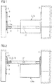
- Fig. 1 shows a top view of the cabin curtain rail attachment 1 according to the present invention.
- a movable curtain rail section 7 is mounted between two guiding rails 8. Each guiding rail 8 is provided with a fixed end stop button 9 at the end pieces 10 of the guiding rails 8 preventing the movable curtain rail section from being detached.
- the movable curtain rail section 7 is in its normal position as shown in Fig. 3 just located below the circuit breaker panel 6 and/or the plexiglass cover 5 respectively.
- a movable end stop button 11 is used to position the movable curtain rail section in a desired position. The movable end stop button 11 can be brought into a locked and an unlocked state.
- the movable end stop button 11 prevents the movable curtain rail section 7 from sliding along the guiding rail 8, while in the unlocked state a sliding of the movable curtain rail section 7 is possible.
- the guiding rails 8 are mounted on monuments 3 of the aircraft 4. Monuments 3 are for example partitions or the galleys, in which the trolleys are usually stored when the catering work is done.
- the movable curtain rail section 7 is coupled to the guiding rail 8 by guiding-rail-coupling means 12 that comprises sliding means 12a.
- the sliding means 12a of the guiding-rail-coupling means 12 are provided with the guiding rail 8 while the rest of the guiding-rail-coupling means 12 are provided with at least on end region of the movable curtain rail section 7.
- the guiding-rail-coupling means 12, in particular the sliding means 12a are configured for guiding the movable curtain rail section 7 along the guiding rail 8, i.e. for transmitting the sliding movement of the movable curtain rail section 7 along the guiding rail 8.
- Fig. 2 shows in top view the cabin curtain rail attachment 1 of Fig. 1 , but in an access position in which maintenance work can be done easily.
- the movable curtain rail section 7 is moved along the guiding rails 8 away from the circuit breaker panel 6 and the plexiglass cover 5.
- the movable end stop button(s) 11 is/are released from its locked state and is/are moved in its unlocked state along the guiding rail(s) 8.
- the plexiglass cover 5 of the circuit breaker panel 6 is openable fully such that maintenance work can be done easily.
- Fig. 3 shows a side view of the cabin curtain rail attachment 1 according to the cabin curtain rail attachment 1 shown in Figs. 1 and 2 .
- the plexiglas cover 5 of the circuit board panel 6 is only openable along a distance d, until the plexiglass cover reaches the movable curtain rail section 7.
- the plexiglass cover 5 can be opened completely, since in the access position as shown in Fig. 2 the movable curtain rail section 7 is moved out of the way.
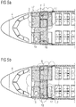
- Figs. 4a , b and 5a , b show how the curtain 2 could be provided with the proposed cabin curtain rail attachment 1 within a cabin.
- a lateral linear movable curtain rail section 7 the crew of the aircraft 4 is able to re-dedicate certain areas in the cabin based on the current flight phase.
- the variations of providing the curtain 2 within the cabin shown in Figs. 4a, b and 5a, b are possible without support of a maintenance crew.
- the curtain 2 provided on the movable curtain rail section 7 will separate the galley 13 from the rest of the cabin (see Fig. 4a ).
- a crew resting area 14 can be separated from the rest of the cabin while the lavatories 15 are still accessible, e.g. on long-haul flights (see Fig. 4b ).
- the cabin curtain rail attachment 1 is for example attached to a or a plurality of monuments 3.
- a U-shaped movable curtain rail section 7 as shown in Fig 5a the crew is able to create a larger and more aesthetical reception area 16 during boarding, as the working areas of the galley area 13 would be hidden by the curtain 2 (see Fig. 5a ).
- the galley area 13 can be separated from the rest of the cabin. The over length of the curtain can be pulled towards an area where the curtain 2 does not disturb the crew activities (see Fig. 5b ).
- curtain-rail-coupling means 17 need to be unlocked.
- the curtain-rail-coupling means 17 can be in a locked state in which they may provide a U-shape or L-shape or a linear shape to the movable curtain rail section 7.
- the curtain-rail-coupling means 17 can comprise tool-less pins with which an unlocking and a locking can be performed easily.
- the Fig. 6 shows in a perspective view an index pin 18.
- the index pin 18 is provided with a knob 19 and a hollow cylindrical body 20 in which a spring (not visible) is housed.
- the index pin 18 can be operated tool-less. By pushing or pulling the knob 19 the index pin 18 will reach the unlocked state presented in Fig. 7a . Due to the spring the index pin 18 will reach automatically the locked state presented in Fig. 7b due to the spring loading, preferably when the knob is released. Due to the spring loading of the spring that is retained within the hollow cylindrical body 20 the spring is automatically pressed against a surface or a recess provided with a surface with which the cylindrical body 20 that is housing the spring can abut.
- Figs. 7a, b show the index pin 18 when it is mounted within the cabin curtain rail attachment 1.
- Such pins preferably index pins, can be used for the guiding-rail-coupling means 12 coupling an end region of the movable curtain rail section 7 to the guiding rail 8, as well as for the curtain-rail-coupling means17 interconnecting at least two movable curtain rail sections 7.
- the shape of the index pin 18 can vary from the index pin shown in Fig. 6 .
- the Figs. 7a, b show the index pin 18 when it is mounted within the cabin curtain rail attachment 1.
- the movable curtain rail section 7 is provided with at least on hole through which the cylindrical body 20 of the index pin 18 is inserted.
- the guiding rail 8 is provided with at least one recess or a hole, in which the cylindrical body 20 of the index pin 18 is engaging in the locked state ( Fig. 7a ) and from which it is released in the unlocked state.
- the Figs. 10a, b show means of length compensation 22 ( Fig. 8 a) and means of angle compensation 23 ( Fig. 8 b) .
- the means of length compensation 22 and/or the means of angle compensation 23 are comprised in the guiding-rail-couplings means 12 (shown in the Figs, 1, 2 , and 3 ).
- the means of length compensation 22 are provided with a slotted hole 24.
- the length of the slotted hole 24 provides a compensation length L along a direction that is essentially parallel to the movable curtain rail section 7.
- the means of angle compensation 23 are provided with a rotating pin axis 26 that allows the rotation of the movable curtain rail section 7 by an angle ⁇ of 0 and 180 ° degree between the movable curtain rail section 7 and the guiding rail 8.
- Fig 8b an angle ⁇ of approximately 60°, 90° and 120° degrees between the movable curtain rail section 7 and the guiding rail 8 is demonstrated schematically.
- the means of length compensation 22 are provided on at least one side of the at least one guiding rail 8 in order to compensate in-motion deformations of the vehicle, preferably in-flight deformations of the aircraft fuselage structure.
- the slotted hole 24 is provided with a length L along which the length compensation can be performed.
- the means of angle compensation 23 are provided on at least one side of one guiding rail 8 in order to compensate in-motion deformations of the vehicle, preferably in-flight deformations of the aircraft fuselage structure, wherein the means of angle compensation 23 comprises the pin attachment 26 configured to adjust the angle between the guiding rail 8 and the movable curtain rail section 7.
- the cabin curtain rail attachment according to the embodiments presented above can be installed on the pelmet or behind the pelmet of a monument 3.
- the description above is made with respect to an aircraft however this shall not limit the scope of the present invention to aircrafts.
- the vehicle cabin curtain rail attachment can be provided to any vehicle, for example such as a train, a bus etc.
Description
- The present invention relates to a vehicle cabin curtain rail attachment, which is suitable for use in an aircraft.
- In a vehicle, in particular an aircraft, various equipment has to be installed within an interior space of the vehicle. For instance, electrical equipment, control components, oxygen supply for aircraft passengers and similar devices are installed behind linings or ceiling elements of the vehicle. These devices may be mounted to a structural component or an installation rail, using bolts, nuts, screws and/or similar fasteners. From time to time, maintenance work has to be done on these devices.
- Whenever a customer airline decides to use a curtain rail for having the option to separate for example a galley area from a passenger area during catering, there are usually several options where to mount the curtain rail.
- For example, according to a first option the curtain rail is routed outboard of the aircraft related circuit breaker panel, the so called 2001VU. Then the curtain will be ending on the galley front or on the standard units and trolleys. This leads to the problem that the curtain would have to be opened, whenever the standard units or trolleys are being used.
- For example, according to a second option the curtain rail is routed to the inboard wall next to the aircraft related circuit breaker panel, to the 2001VU, which is usually covered by a plexiglass cover. However, in case of failure, maintenance or for another reason an electronic device behind the plexiglass cover has to be dismounted or exchanged, the plexiglass cover is usually not fully openable for access to the circuit breakers any more as the curtain rail is located just below the plexiglass cover. In this situation, the plexiglass cover will only open as far as until the plexiglass cover rests on the curtain rail. This in turn makes maintenance work complicated and time consuming. However, between two flights of an aircraft, the time for maintenance work is short.
-
US 8, 684, 308 (B2 ) orEP 2 26 8 54 2 (B1 - However, in case of maintenance, there is still the problem that the plexiglass cover cannot be opened such that enough space is available that the maintenance can be performed as short and as comfortable as possible.
- Furthermore,
US 2012/234976 A1 refers to a ceiling panel for attaching a curtain in a cabin of a transportation device with two attachment units, which are designed as rails. A curtain attachment unit is movable along the rail in a longitudinal direction of the ceiling panel. The curtain attachment unit is movable in a transverse direction relative to the longitudinal direction of the ceiling panel. -
CN 102 774 500 A refers to a curtain rail section being arranged at guiding rails, along which the curtain rail section is movable. -
CN 2005 273 878 U -
US 2012/273613 A1 refers a to mounting module being arranged in a cabin of an aircraft, wherein the mounting module can be folded into a center hatrack. -
US 4 120 474 A refers to a drapery support assembly designed for a fixed mounting in a room of a building and for a curtain rod being provided with a bracket. The bracket is movable along a rail. - It is an object of the present invention to provide a curtain rail attachment that is easily and quickly taken outside a space needed for maintenance work and also moved back quickly after the maintenance work is finished.
- This object is solved by vehicle curtain rail attachment according to
independent claim 1. Preferred embodiments are defined by the dependent claims. - According to an aspect to better understand the present disclosure, a vehicle cabin curtain rail attachment is provided which comprises a guiding rail adapted to be mounted fixedly within a cabin of the vehicle and a movable curtain rail section for receiving and/or guiding a curtain, wherein the movable curtain rail section is adapted to slide along the guiding rail to a desired position. The desired position is defined as a position on the guiding rail at which the movable curtain rail section shall be detachably fixed to the guiding rail. The guiding rail is mounted fixedly to a monument of the vehicle or to another space within the cabin by using screws or the like. The movable curtain rail section is attached to the guiding rail in a manner that it can slide along the guiding rail. Advantageously, the curtain rail section can be moved out of the way when necessary, i.e. in situations where maintenance work has to be performed, and back, i.e. after the maintenance work is finished.
- The movable curtain rail section is retained in the desired position along the guiding rail by at least one movable end stop button being adapted to slide along the guiding rail and being adapted to engage with the guiding rail in order to fix the movable end stop button to the guiding rail in a locking position. The desired locking position of the movable end stop button is located adjacent to the desired position of the movable curtain rail section. In the locking position the movable end stop engages with the movable curtain rail section and the guiding rail. The movable end stop button is movable along the guiding rail together with the movable curtain rails section. When the desired position of the movable curtain rail section is reached at a position somewhere along the guiding rail, the at least one movable end stop button is positioned in its fixed state, i.e. the desired locking state, in which the at least one movable end stop button engages with the guiding rail and with the movable curtain rail section. The at least one end stop button is detachable from the fixed state. The locking and the unlocking of the end stop button can be performed without tooling. It is an advantage that even the crew can get access to the circuit breaker for example during a flight, if necessary.
- The movable curtain rail section is movable along the at least one guiding rail between two fixed end stop buttons being mounted at the end pieces of the guiding rail and being adapted to prevent the movable curtain rail section from being detached from the guiding rail. The two fixed end stop buttons prevent the movable curtain rail section from getting loose from the guiding rail. The fixed end stop buttons at the end pieces of the guiding rails provide safety in situations where the movable curtain rail section is sliding along the guiding rail and in case of a failure of the movable end stop buttons. It would also be possible to use screws for the fixed end stop buttons.
- The movable end stop buttons are adapted to be in an unlocked state in which they are movable along the guiding section to the desired position and to be in a locked state in which they a detachably fixed in the desired position for retaining the movable curtain rail section in the desired position. In this way, the curtain can be arranged so that is gives as much comfort as possible to the crew and to the passengers of the vehicle, in particular of the aircraft.
- The movable and, advantageously also the fixed, end stop button comprises a pin, in particular an index pin, configured for achieving a locked state and an unlocked state. The pin comprises a knob for achieving the unlocked state by using, preferably pushing or pulling, the knob and a spring for achieving automatically the locked state by spring load. Thus, the index pin comprises a knob the use thereof results in the achievement of the unlocked state. In the unlocked state the pin, particularly the index pin, together with the curtain section are slidable along the guiding rail, in particular between the two fixed end stop buttons. Furthermore, the index pin comprises at least on spring, which provides a spring loading. The at least one spring is located within a hollow pin body, preferably a hollow cylindrical section of the pin body. The locked state is achieved automatically by spring loading. For achieving the locked state automatically it is for example sufficient to release the knob of the pin, which then will be spring loaded. In the locked state of the pin the pin, and particularly the curtain rail section positioned between two locked pins, are not movable along the guiding rail. At most the movable curtain rail section is only movable between the two locked movable pins, provided that the two locked movable pins are located a space apart from each other. The movable curtain rail section might then be only slidable along said space. Such a situation can be evoked, if it is needed that the movable curtain rail section remains movable along a defined section of the guiding rail.This section of the guiding rail is defined as "space" above. It is possible that the fixed end stop buttons are provided with screws, since the fixed end stop buttons need not to be operated. It is also possible that the fixed end stop buttons are provided as detachably fixable pins. The advantage of using a pin, in particular an index pin, for at least the movable end stop buttons is the usage thereof without extra tooling.
- Advantageously, the vehicle cabin curtain rail attachment comprises a plurality of guiding rails that are mounted fixedly within the cabin, wherein the movable curtain rail section is attached between a pair of guiding rails. The pair of guiding rails are spaced apart from each other that the movable curtain rail section can be attached to the guiding rails easily. Thus, the spacing apart of the pair guiding rails corresponds essentially to the length of the movable curtain rail section. The pair of guiding rails are mounted within the cabin, essentially, parallel to each other. Providing the vehicle cabin curtain rail attachment with a pair of guiding rails improves the safety of the attachment as such.
- Each guiding rail is provided with two fixed end stop buttons for preventing the movable curtain rail section from being detached from the guiding rail, wherein one of the fixed end stop buttons is positioned fixedly at each end piece of the guiding rail, and wherein at least one of the guiding rails comprises two movable end stop buttons adapted to retain the movable curtain rail section at the desired position along the guiding rail. While two fixed end stop buttons are provided at the end pieces of a guiding rail, at least two movable end stop buttons are additionally provided which are slideable along the guiding rail together with the movable curtain rail section. The movable end stop buttons can preferably be operated without tooling and are provided at a position somewhere between the two fixed end-stop buttons. It is an advantage that even the crew can lock and unlock the movable end stop buttons during a flight, if necessary.
- Preferably, each end piece of the movable curtain rail section is attached to one guiding rail by a guiding-rail-coupling means configured for guiding the movable curtain rail section along the guiding rail. By coupling the movable curtain rail section via guiding-rail-coupling means to the guiding rail, a secure guiding of the curtain rail section along or in the guiding rail(s) is available. The guiding-rail-coupling means can be mounted fixedly to the movable curtain rail section, while the mounting to the guiding rail is performed such that a slidable guidance along the guiding rail is achieved. Preferably, each of the guiding rails is provided with two tracks, between which the guiding-rail-coupling means is or are provided in a movable or slidable manner. It is also possible that each of the guiding rails is provided with a slotted grove in which the guiding-rail-coupling means can slidably engage.
- Furthermore, the vehicle cabin curtain rail attachment is provided with means of length compensation on at least one end region of one guiding rail in order to compensate in-motion deformations of the vehicle, preferably in-flight deformations of the aircraft fuselage structure, wherein the means of length compensation comprises a slotted hole. Especially in aircrafts, during a flight the fuselage structure may deform due to changes in the external pressure and due to flight loads. Advantageously, the means of length compensation allows for compensating length deformations. The length compensation available corresponds to the length of the slotted hole. Such length compensation means can be provided at one end piece or at both end pieces of the movable curtain rail section.
- Further advantageously, the vehicle cabin curtain rail attachment is provided with means of angle compensation on at least one end region of one guiding rail section in order to compensate in-motion deformations of the vehicle, preferably in-flight deformations of the aircraft fuselage structure, wherein the means of angle compensation comprises preferably a pin attachment configured to adjust an angle between the guiding rail and the movable curtain rail section. Preferably to adjust an angle deviating from a 90° degree angle between an axis of the guiding rail and an axis of the movable curtain rail section being essentially perpendicular to each other when not deformed. Further preferably, the means of angle compensation comprises an axis of rotation via which the angle compensation is transmitted between the movable curtain rail section and the guiding rail(s). The axis of rotation is provided perpendicularly to the axis along which the angle compensation is to be performed. With the angle compensation means any angle between 0 and 180° degrees, preferably ±90 ° degrees, can be compensated. Such angle compensation means can be provided at one end piece or at both end pieces of the movable curtain rail section. Preferably one angle compensation means is provided at one end piece while at the other end piece a length compensation means is provided. It is also possible that at the same end piece a length compensation means and an angle compensation means is provided.
- Preferably a vehicle cabin curtain rail attachment is provided, wherein a L- shaped or an U-shaped curtain rail section is provided for connecting to at least one guiding rail, preferably for connecting to a pair of guiding rails. The L-shaped or U-shaped movable curtain rail section comprises at least two or three, preferably linear, movable curtain rail portions, that are coupled by curtain-rail-section-coupling means configured for shifting a curtain from one, preferably linear, curtain rail section to the adjacent curtain rail section. The curtain-rail-section-coupling means allows the transition of a curtain from one curtain rail section to the other. The curtain-rail-section-coupling means are mounted between at least two movable curtain rail sections detachably.
- Of course, the curtain-rail-section-couplings means are adjustable into a locked state in which the curtain rail sections are detachably fixed with respect to each other and into an unlocked state in which the curtain rail sections are freely movable with respect to each other. In this way, the shape of the movable curtain rail section can be modified from being linear to being L-shaped or being U-shaped and back vice versa. In this way the shape of the movable curtain rail section can be varied as much as needed, especially during a flight. This in turn enhances the comfort provided by a curtain provided in a vehicle cabin curtain rail attachment. The curtain-rail-section-couplings means comprises a knob for achieving the unlocked state and a spring for achieving the locked position automatically by spring load. In this way the crew can without tooling vary the shape of movable curtain rail section.
- Preferred embodiments of the vehicle cabin curtain rail attachment, in particular for an aircraft, are described in greater detail with reference to the attached schematic drawings in the following, wherein
- Fig. 1
- shows a top view of the vehicle cabin curtail rail arrangement according to the present invention in the normal position, for example during a flight,
- Fig. 2
- shows a top view of the vehicle cabin curtail rail arrangement according to the present invention in the access position, for example during maintenance work,
- Fig. 3
- shows a side view of the vehicle cabin curtail rail arrangement according to the present invention,
- Figs. 4a, b
- show two possible positions of the movable curtain rail section,
- Figs. 5a, b
- show two possible further positions of the movable curtain rail section,
- Fig. 6
- shows an index pin in perspective side views,
- Figs. 7a, b
- show a side view of the index pin mounted in the vehicle cabin curtail rail arrangement in the locked state (
Fig. 7a ) and the unlocked state (Fig. 7b ), and - Figs. 8a, b
- show means of length compensation (
Fig. 8a ) and means of angle compensation (Fig. 8b ). - The following detailed description of the schematic drawings focuses on the illustrated implementation variants of a vehicle cabin curtain rail attachment in particular for an aircraft.
-
Fig. 1 shows a top view of the cabincurtain rail attachment 1 according to the present invention. A movablecurtain rail section 7 is mounted between two guidingrails 8. Each guidingrail 8 is provided with a fixedend stop button 9 at the end pieces 10 of the guidingrails 8 preventing the movable curtain rail section from being detached. The movablecurtain rail section 7 is in its normal position as shown inFig. 3 just located below the circuit breaker panel 6 and/or the plexiglass cover 5 respectively. A movableend stop button 11 is used to position the movable curtain rail section in a desired position. The movableend stop button 11 can be brought into a locked and an unlocked state. In the locked state the movableend stop button 11 prevents the movablecurtain rail section 7 from sliding along the guidingrail 8, while in the unlocked state a sliding of the movablecurtain rail section 7 is possible. The guiding rails 8 are mounted onmonuments 3 of theaircraft 4.Monuments 3 are for example partitions or the galleys, in which the trolleys are usually stored when the catering work is done. The movablecurtain rail section 7 is coupled to the guidingrail 8 by guiding-rail-coupling means 12 that comprises slidingmeans 12a. The sliding means 12a of the guiding-rail-coupling means 12 are provided with the guidingrail 8 while the rest of the guiding-rail-coupling means 12 are provided with at least on end region of the movablecurtain rail section 7. The guiding-rail-coupling means 12, in particular the slidingmeans 12a, are configured for guiding the movablecurtain rail section 7 along the guidingrail 8, i.e. for transmitting the sliding movement of the movablecurtain rail section 7 along the guidingrail 8. -
Fig. 2 shows in top view the cabincurtain rail attachment 1 ofFig. 1 , but in an access position in which maintenance work can be done easily. In the access position shown inFig. 2 the movablecurtain rail section 7 is moved along the guidingrails 8 away from the circuit breaker panel 6 and the plexiglass cover 5. For doing so the movable end stop button(s) 11 is/are released from its locked state and is/are moved in its unlocked state along the guiding rail(s) 8. As a result the plexiglass cover 5 of the circuit breaker panel 6 is openable fully such that maintenance work can be done easily. -
Fig. 3 shows a side view of the cabincurtain rail attachment 1 according to the cabincurtain rail attachment 1 shown inFigs. 1 and 2 . In the side view ofFig. 3 it becomes clear that in the normal position the plexiglas cover 5 of the circuit board panel 6 is only openable along a distance d, until the plexiglass cover reaches the movablecurtain rail section 7. According to the present invention however, the plexiglass cover 5 can be opened completely, since in the access position as shown inFig. 2 the movablecurtain rail section 7 is moved out of the way. -
Figs. 4a ,b and 5a ,b show how thecurtain 2 could be provided with the proposed cabincurtain rail attachment 1 within a cabin. By using a lateral linear movablecurtain rail section 7 the crew of theaircraft 4 is able to re-dedicate certain areas in the cabin based on the current flight phase. By using the proposed tool-less locking/unlocking principles the variations of providing thecurtain 2 within the cabin shown inFigs. 4a, b and5a, b are possible without support of a maintenance crew. - For example during boarding or during catering activities inside the
galley area 13 comprisingmonuments 3 thecurtain 2 provided on the movablecurtain rail section 7 will separate thegalley 13 from the rest of the cabin (seeFig. 4a ). During flight and after catering activities acrew resting area 14 can be separated from the rest of the cabin while thelavatories 15 are still accessible, e.g. on long-haul flights (seeFig. 4b ). The cabincurtain rail attachment 1 is for example attached to a or a plurality ofmonuments 3. - If a U-shaped movable
curtain rail section 7 as shown inFig 5a is used the crew is able to create a larger and moreaesthetical reception area 16 during boarding, as the working areas of thegalley area 13 would be hidden by the curtain 2 (seeFig. 5a ). During catering activities thegalley area 13 can be separated from the rest of the cabin. The over length of the curtain can be pulled towards an area where thecurtain 2 does not disturb the crew activities (seeFig. 5b ). It is possible to provide the movablecurtain rail section 7 in L-shape. For providing the transition between a U-shaped (or L-shaped) movable curtailrail section 7 ofFig. 5a to a linear movablecurtain rail section 7 ofFig. 5b curtain-rail-coupling means 17 need to be unlocked. The curtain-rail-coupling means 17 can be in a locked state in which they may provide a U-shape or L-shape or a linear shape to the movablecurtain rail section 7. When the curtain-rail-coupling means 17 are unlocked the movablecurtain rail sections 7 can be brought into position and locked afterwards. For example the curtain-rail-coupling means 17 can comprise tool-less pins with which an unlocking and a locking can be performed easily. - The
Fig. 6 shows in a perspective view anindex pin 18. Theindex pin 18 is provided with aknob 19 and a hollowcylindrical body 20 in which a spring (not visible) is housed. Theindex pin 18 can be operated tool-less. By pushing or pulling theknob 19 theindex pin 18 will reach the unlocked state presented inFig. 7a . Due to the spring theindex pin 18 will reach automatically the locked state presented inFig. 7b due to the spring loading, preferably when the knob is released. Due to the spring loading of the spring that is retained within the hollowcylindrical body 20 the spring is automatically pressed against a surface or a recess provided with a surface with which thecylindrical body 20 that is housing the spring can abut. The abutting of thecylindrical body 20 on a surface generates an abutting force that is acting in a direction opposed to the direction of a spring loading force. The automatically reaching of the locked state is due to the equilibrium of the spring loading force and the abutting force.TheFigs. 7a, b show theindex pin 18 when it is mounted within the cabincurtain rail attachment 1. Such pins, preferably index pins, can be used for the guiding-rail-coupling means 12 coupling an end region of the movablecurtain rail section 7 to the guidingrail 8, as well as for the curtain-rail-coupling means17 interconnecting at least two movable curtain rail sections 7.The shape of theindex pin 18 can vary from the index pin shown inFig. 6 . - The
Figs. 7a, b show theindex pin 18 when it is mounted within the cabincurtain rail attachment 1. For example according toFigs. 7a, b the movablecurtain rail section 7 is provided with at least on hole through which thecylindrical body 20 of theindex pin 18 is inserted. Furthermore, the guidingrail 8 is provided with at least one recess or a hole, in which thecylindrical body 20 of theindex pin 18 is engaging in the locked state (Fig. 7a ) and from which it is released in the unlocked state. The Figs. 10a, b show means of length compensation 22 (Fig. 8 a) and means of angle compensation 23 (Fig. 8 b) . The means oflength compensation 22 and/or the means ofangle compensation 23 are comprised in the guiding-rail-couplings means 12 (shown in theFigs, 1, 2 , and3 ). The means oflength compensation 22 are provided with a slottedhole 24. The length of the slottedhole 24 provides a compensation length L along a direction that is essentially parallel to the movablecurtain rail section 7. The means ofangle compensation 23 are provided with arotating pin axis 26 that allows the rotation of the movablecurtain rail section 7 by an angle Θ of 0 and 180 ° degree between the movablecurtain rail section 7 and the guidingrail 8. For example, inFig 8b an angle Θ of approximately 60°, 90° and 120° degrees between the movablecurtain rail section 7 and the guidingrail 8 is demonstrated schematically. The means oflength compensation 22 are provided on at least one side of the at least one guidingrail 8 in order to compensate in-motion deformations of the vehicle, preferably in-flight deformations of the aircraft fuselage structure. The slottedhole 24 is provided with a length L along which the length compensation can be performed. The means ofangle compensation 23 are provided on at least one side of one guidingrail 8 in order to compensate in-motion deformations of the vehicle, preferably in-flight deformations of the aircraft fuselage structure, wherein the means ofangle compensation 23 comprises thepin attachment 26 configured to adjust the angle between the guidingrail 8 and the movablecurtain rail section 7. - The cabin curtain rail attachment according to the embodiments presented above can be installed on the pelmet or behind the pelmet of a
monument 3. The description above is made with respect to an aircraft however this shall not limit the scope of the present invention to aircrafts. Instead, the vehicle cabin curtain rail attachment can be provided to any vehicle, for example such as a train, a bus etc. -
- 1
- cabin curtain rail attachment
- 2
- curtain
- 3
- monument
- 4
- aircraft
- 5
- plexiglass cover
- 6
- circuit breaker panel
- 7
- movable curtain rail section
- 8
- guiding rail
- 9
- fixed end stop button
- 10
- end piece (of the guiding rail)
- 11
- movable end stop button
- 12
- guiding-rail-coupling means
- 12a
- sliding means
- 13
- galley area
- 14
- crew area
- 15
- lavatory
- 16
- aesthetical reception area
- 17
- curtain-rail-coupling means
- 18
- index pin
- 19
- knob
- 20
- cylindrical body
- 21
- end side (of the movable curtain rail section)
- 22
- length compensation means
- 23
- angle compensation means
- 24
- slotted hole
- 25
- length
- 26
- pin attachment having a rotation pin axis
- d
- distance
- L
- compensation length
- Θ
- angle
Claims (14)
- Vehicle cabin curtain rail attachment (1) comprising:a guiding rail (8) adapted to be mounted fixedly within a cabin of the vehicle and a movable curtain rail section (7) for receiving and/or guiding a curtain (2),wherein the movable curtain rail section (7) is adapted to slide along the guiding rail (8) to a desired position,wherein the movable curtain rail section (7) is configured to be retained in the desired position along the guiding rail (8) by at least one movable end stop button (11) being adapted to slide along the guiding rail (8) and being adapted to engage with the guiding rail (8) in order to fix the at least one movable end stop button (11) to the guiding rail (8) in a locking position, andwherein the at least one movable end stop button (11) comprises a pin (18) configured for achieving a locked state and an unlocked state.
- Vehicle cabin curtain rail attachment (1) according to claim 1, wherein the movable curtain rail section (7) is movable along the at least one guiding rail (8) between two fixed end stop buttons (9) being mounted at end pieces (10) of the guiding rail (8) and being adapted to prevent the movable curtain rail section (7) from being detached from the guiding rail (8).
- Vehicle cabin curtain rail attachment (1) according to claim 1 or 2, wherein the at least one movable end stop button (11) is switchable between an unlocked state in which it is movable along the guiding section (8) to the locking position and a locked state in which it is detachably fixed in the locking position for retaining the movable curtain rail section (7) in the desired position.
- Vehicle cabin curtain rail attachment (1) according to claim 2, wherein the fixed end stop buttons (9) comprise a pin (18), in particular an index pin (18), configured for achieving a locked state and an unlocked state.
- Vehicle cabin curtain rail attachment (1) according to claim 4, wherein the pin (18) comprises a knob (19) for achieving the unlocked state by using, preferably pushing or pulling, the knob (19) and a spring for achieving automatically the locked state by spring load.
- Vehicle cabin curtain rail attachment (1) according to one of claims 1 to 5, wherein a pair of guiding rails (8) is adapted to be mounted fixedly within the cabin, wherein the movable curtain rail section (7) is attached between the two guiding rails (8) of said pair.
- Vehicle cabin curtain rail attachment (1) according to one of claims 1 to 6, wherein a plurality guiding rails (8) is provided each thereof with two fixed end stop buttons (9) for preventing the movable curtain rail section (7) from being detached from the guiding rail (8), wherein the fixed end stop buttons (9) are positioned fixedly at each end piece (10) of the guiding rail (8), and wherein at least one of the guiding rails (8) comprises two movable end stop buttons (11) adapted to retain the movable curtain rail section (7) at the desired position along the guiding rail (8).
- Vehicle cabin curtain rail attachment (1) according to one of claims 1 to 7, wherein the movable curtain rail section (7) comprises at least one end piece (21), wherein each end piece (21) of the movable curtain rail section (7) is attached to one guiding rail (8) by a guiding-rail-coupling means (12) configured for guiding the movable curtain rail section (7) along the guiding rail (8).
- Vehicle cabin curtain rail attachment (1) according to one of claims 1 to 8, wherein means of length compensation (22) are provided on at least one end region of at least one guiding rail (8) in order to compensate in-motion deformations of the vehicle wherein the means of length compensation (22) comprises a slotted hole (24).
- Vehicle cabin curtain rail attachment (1) according to one of claims 1 to 9, wherein means of angle compensation (23) are provided on at least one side region of the guiding rail (8) in order to compensate in-motion deformations of the vehicle, wherein the means of angle compensation (23) comprise a pin attachment (26) configured to adjust an angle between the guiding rail (8) and the movable curtain rail section (7), preferably to adjust an angle deviating from a 90° degree angle between an axis of the guiding rail (8) and an axis of the movable curtain rail section (7) being essentially perpendicular to each other when not deformed.
- Vehicle cabin curtain rail attachment (1) according to one of claims 1 to 10, wherein a L-shaped or an U-shaped movable curtain rail section (7) is provided for connecting to at least one guiding rail (8), preferably for connecting to a pair guiding rails (8).
- Vehicle cabin curtain rail attachment (1) according to claim 11, wherein the L-shaped or U-shaped movable curtain rail section (7) comprises at least two, preferably linear, movable curtain rail portions, that are coupled by curtain-rail-section-coupling means (17) configured for supporting the shifting of the curtain (2) from one, preferably linear, movable curtain rail section (7) to the adjacent movable curtain rail section (7).
- Vehicle cabin curtain rail attachment (1) according to claim 12, wherein the curtain-rail-section-couplings means are adjustable into a locked state in which the movable curtain rail sections (7) are detachably fixed with respect to each other and into an unlocked state in which the movable curtain rail sections (7) are freely movable with respect to each other.
- Vehicle cabin curtain rail attachment (1) according to claim 12 or 13, wherein the curtain-rail-section-couplings means comprises a knob (19) for achieving the unlocked state and a spring for achieving the locked position automatically by spring load.
Priority Applications (2)
| Application Number | Priority Date | Filing Date | Title |
|---|---|---|---|
| EP16186258.6A EP3290340B1 (en) | 2016-08-30 | 2016-08-30 | Lateral linear moving curtain rail |
| US15/682,755 US20180057168A1 (en) | 2016-08-30 | 2017-08-22 | Lateral linear moving curtain rail |
Applications Claiming Priority (1)
| Application Number | Priority Date | Filing Date | Title |
|---|---|---|---|
| EP16186258.6A EP3290340B1 (en) | 2016-08-30 | 2016-08-30 | Lateral linear moving curtain rail |
Publications (2)
| Publication Number | Publication Date |
|---|---|
| EP3290340A1 EP3290340A1 (en) | 2018-03-07 |
| EP3290340B1 true EP3290340B1 (en) | 2020-04-15 |
Family
ID=56842735
Family Applications (1)
| Application Number | Title | Priority Date | Filing Date |
|---|---|---|---|
| EP16186258.6A Active EP3290340B1 (en) | 2016-08-30 | 2016-08-30 | Lateral linear moving curtain rail |
Country Status (2)
| Country | Link |
|---|---|
| US (1) | US20180057168A1 (en) |
| EP (1) | EP3290340B1 (en) |
Families Citing this family (1)
| Publication number | Priority date | Publication date | Assignee | Title |
|---|---|---|---|---|
| US10737788B2 (en) * | 2017-10-20 | 2020-08-11 | The Boeing Company | Systems and methods for adaptively positioning a cross-aisle curtain header assembly within a vehicle |
Family Cites Families (26)
| Publication number | Priority date | Publication date | Assignee | Title |
|---|---|---|---|---|
| US3030060A (en) * | 1960-01-15 | 1962-04-17 | Breuer Karl | Curtain rod mounting devices |
| US3296651A (en) * | 1964-12-16 | 1967-01-10 | Baker Drapery Studio | Drapery support |
| US3346227A (en) * | 1966-10-04 | 1967-10-10 | Swish Prod | Curtain suspension devices |
| GB1279170A (en) * | 1970-11-16 | 1972-06-28 | Hunter Douglas | Curtain track fittings |
| US3818543A (en) * | 1971-06-14 | 1974-06-25 | Baker Drapery Corp | Drapery support |
| DE7612227U1 (en) * | 1976-04-17 | 1976-12-09 | Bratschi, Konrad, Muri (Schweiz) | STRIPED CURTAIN |
| US4120474A (en) * | 1976-10-06 | 1978-10-17 | Hurley's Concepts, Inc. | Drapery support assembly |
| US4639031A (en) * | 1985-04-17 | 1987-01-27 | Randall Industries | Repositionable thermal insulating truck bulkhead |
| US5421394A (en) * | 1993-04-23 | 1995-06-06 | Forrest; Kim | Self-contained and removable drapery mounting device |
| US6499186B1 (en) * | 2000-11-06 | 2002-12-31 | Anita Arentsen | Hinged drapery rod |
| US6585208B1 (en) * | 2002-01-25 | 2003-07-01 | Hunter Douglas Inc. | Universal bracket for mounting coverings for architectural openings |
| TW551122U (en) * | 2002-12-23 | 2003-09-01 | Yi-Ren Huang | Improved structure of lateral wheel set for curtain rail |
| US7273336B2 (en) * | 2003-11-03 | 2007-09-25 | Jac Products | Divider apparatus and method for use with a bed of a motor vehicle |
| US20080156951A1 (en) * | 2006-12-29 | 2008-07-03 | Tzong-Fu Lin | Foldable traverse rod |
| DE102008014929A1 (en) | 2008-03-19 | 2009-10-22 | Airbus Deutschland Gmbh | Universal arrangement for receiving a curtain rail for a curtain |
| US20100218906A1 (en) * | 2009-02-27 | 2010-09-02 | Tribute Window Coverings Inc. | Modular Shade System |
| DE102009012754A1 (en) * | 2009-03-12 | 2010-09-16 | Airbus Deutschland Gmbh | Ceiling panel with curtain rail in a transport cabin |
| US20110191983A1 (en) * | 2010-02-10 | 2011-08-11 | My Home Global Company | Curtain rail structure |
| DE102010050108B3 (en) * | 2010-10-29 | 2012-04-26 | Airbus Operations Gmbh | Suspension device for suspending visual separation between two areas of passenger cabin transportation unit, has rail, suspension module and coupling device |
| US8888175B2 (en) * | 2010-11-03 | 2014-11-18 | Zodiac Seat Shells Us Llc | Slide-out bed pod |
| EP2669196B1 (en) * | 2012-05-31 | 2019-07-03 | Airbus Operations GmbH | Aircraft cabin curtain rail assembly kit, aircraft cabin curtain rail and aircraft with an aircraft cabin having a curtain supported on such an aircraft cabin curtain rail |
| CN102774500A (en) * | 2012-07-30 | 2012-11-14 | 成都富凯飞机工程服务有限公司 | Airplane cabin curtain assembly |
| US20140224439A1 (en) * | 2013-02-08 | 2014-08-14 | Beme International, Llc | Reversible bracket mounting system for window treatment support apparatus |
| WO2015090432A1 (en) * | 2013-12-20 | 2015-06-25 | Inter Ikea Systems B.V. | Hanging system |
| US9499271B2 (en) * | 2015-04-09 | 2016-11-22 | The Boeing Company | Systems and methods for positioning a section divider assembly within a vehicle |
| CN205273878U (en) * | 2015-12-28 | 2016-06-01 | 广州飞机维修工程有限公司 | Cabin link plate subassembly |
-
2016
- 2016-08-30 EP EP16186258.6A patent/EP3290340B1/en active Active
-
2017
- 2017-08-22 US US15/682,755 patent/US20180057168A1/en not_active Abandoned
Non-Patent Citations (1)
| Title |
|---|
| None * |
Also Published As
| Publication number | Publication date |
|---|---|
| EP3290340A1 (en) | 2018-03-07 |
| US20180057168A1 (en) | 2018-03-01 |
Similar Documents
| Publication | Publication Date | Title |
|---|---|---|
| EP3129281B1 (en) | Retaining system for a door element and method for locking and releasing a door element on board of an aircraft | |
| US8286917B2 (en) | Attachment assembly and method | |
| EP2822854B1 (en) | Aircraft cabin bin retrofit | |
| EP2316733B1 (en) | Aircraft galley units | |
| US10189571B2 (en) | Module for an aircraft cabin with a seat fastened to a door | |
| US9573689B2 (en) | Apparatus for holding a cabin attendant seat, cabin arrangement in a vehicle and vehicle having a cabin and such a cabin arrangement | |
| EP3209561B1 (en) | Arrangement with a partitioning device in a cabin of a vehicle and aircraft with a cabin and such an arrangement | |
| US20220332423A1 (en) | Passenger seat unit with multi-track sliding door | |
| US10829195B2 (en) | Bulkhead assembly with pocket door for aircraft interior | |
| EP3248875B1 (en) | Flight attendant seat, system comprising flight attendant seat as well as arrangement and aircraft area comprising system | |
| US20230249830A1 (en) | Carrier device, seating area divider and vehicle cabin | |
| US11299274B1 (en) | Aircraft passenger compartment with an accessibility door | |
| EP3290340B1 (en) | Lateral linear moving curtain rail | |
| EP3786063A1 (en) | Stowable door folding table | |
| EP3848285B1 (en) | Adapter plate for an aircraft seat | |
| US11370547B2 (en) | Mobile class divider for aircraft cabin | |
| US11377215B1 (en) | Stowable flight attendant seat system |
Legal Events
| Date | Code | Title | Description |
|---|---|---|---|
| PUAI | Public reference made under article 153(3) epc to a published international application that has entered the european phase |
Free format text: ORIGINAL CODE: 0009012 |
|
| STAA | Information on the status of an ep patent application or granted ep patent |
Free format text: STATUS: THE APPLICATION HAS BEEN PUBLISHED |
|
| AK | Designated contracting states |
Kind code of ref document: A1 Designated state(s): AL AT BE BG CH CY CZ DE DK EE ES FI FR GB GR HR HU IE IS IT LI LT LU LV MC MK MT NL NO PL PT RO RS SE SI SK SM TR |
|
| AX | Request for extension of the european patent |
Extension state: BA ME |
|
| STAA | Information on the status of an ep patent application or granted ep patent |
Free format text: STATUS: REQUEST FOR EXAMINATION WAS MADE |
|
| 17P | Request for examination filed |
Effective date: 20180504 |
|
| RBV | Designated contracting states (corrected) |
Designated state(s): AL AT BE BG CH CY CZ DE DK EE ES FI FR GB GR HR HU IE IS IT LI LT LU LV MC MK MT NL NO PL PT RO RS SE SI SK SM TR |
|
| STAA | Information on the status of an ep patent application or granted ep patent |
Free format text: STATUS: EXAMINATION IS IN PROGRESS |
|
| 17Q | First examination report despatched |
Effective date: 20190111 |
|
| GRAP | Despatch of communication of intention to grant a patent |
Free format text: ORIGINAL CODE: EPIDOSNIGR1 |
|
| STAA | Information on the status of an ep patent application or granted ep patent |
Free format text: STATUS: GRANT OF PATENT IS INTENDED |
|
| INTG | Intention to grant announced |
Effective date: 20191127 |
|
| GRAS | Grant fee paid |
Free format text: ORIGINAL CODE: EPIDOSNIGR3 |
|
| GRAA | (expected) grant |
Free format text: ORIGINAL CODE: 0009210 |
|
| STAA | Information on the status of an ep patent application or granted ep patent |
Free format text: STATUS: THE PATENT HAS BEEN GRANTED |
|
| AK | Designated contracting states |
Kind code of ref document: B1 Designated state(s): AL AT BE BG CH CY CZ DE DK EE ES FI FR GB GR HR HU IE IS IT LI LT LU LV MC MK MT NL NO PL PT RO RS SE SI SK SM TR |
|
| REG | Reference to a national code |
Ref country code: CH Ref legal event code: EP |
|
| REG | Reference to a national code |
Ref country code: DE Ref legal event code: R096 Ref document number: 602016033940 Country of ref document: DE |
|
| REG | Reference to a national code |
Ref country code: IE Ref legal event code: FG4D |
|
| REG | Reference to a national code |
Ref country code: AT Ref legal event code: REF Ref document number: 1256989 Country of ref document: AT Kind code of ref document: T Effective date: 20200515 |
|
| REG | Reference to a national code |
Ref country code: NL Ref legal event code: MP Effective date: 20200415 |
|
| REG | Reference to a national code |
Ref country code: LT Ref legal event code: MG4D |
|
| PG25 | Lapsed in a contracting state [announced via postgrant information from national office to epo] |
Ref country code: IS Free format text: LAPSE BECAUSE OF FAILURE TO SUBMIT A TRANSLATION OF THE DESCRIPTION OR TO PAY THE FEE WITHIN THE PRESCRIBED TIME-LIMIT Effective date: 20200815 Ref country code: NL Free format text: LAPSE BECAUSE OF FAILURE TO SUBMIT A TRANSLATION OF THE DESCRIPTION OR TO PAY THE FEE WITHIN THE PRESCRIBED TIME-LIMIT Effective date: 20200415 Ref country code: LT Free format text: LAPSE BECAUSE OF FAILURE TO SUBMIT A TRANSLATION OF THE DESCRIPTION OR TO PAY THE FEE WITHIN THE PRESCRIBED TIME-LIMIT Effective date: 20200415 Ref country code: PT Free format text: LAPSE BECAUSE OF FAILURE TO SUBMIT A TRANSLATION OF THE DESCRIPTION OR TO PAY THE FEE WITHIN THE PRESCRIBED TIME-LIMIT Effective date: 20200817 Ref country code: NO Free format text: LAPSE BECAUSE OF FAILURE TO SUBMIT A TRANSLATION OF THE DESCRIPTION OR TO PAY THE FEE WITHIN THE PRESCRIBED TIME-LIMIT Effective date: 20200715 Ref country code: GR Free format text: LAPSE BECAUSE OF FAILURE TO SUBMIT A TRANSLATION OF THE DESCRIPTION OR TO PAY THE FEE WITHIN THE PRESCRIBED TIME-LIMIT Effective date: 20200716 Ref country code: SE Free format text: LAPSE BECAUSE OF FAILURE TO SUBMIT A TRANSLATION OF THE DESCRIPTION OR TO PAY THE FEE WITHIN THE PRESCRIBED TIME-LIMIT Effective date: 20200415 Ref country code: FI Free format text: LAPSE BECAUSE OF FAILURE TO SUBMIT A TRANSLATION OF THE DESCRIPTION OR TO PAY THE FEE WITHIN THE PRESCRIBED TIME-LIMIT Effective date: 20200415 |
|
| REG | Reference to a national code |
Ref country code: AT Ref legal event code: MK05 Ref document number: 1256989 Country of ref document: AT Kind code of ref document: T Effective date: 20200415 |
|
| PG25 | Lapsed in a contracting state [announced via postgrant information from national office to epo] |
Ref country code: RS Free format text: LAPSE BECAUSE OF FAILURE TO SUBMIT A TRANSLATION OF THE DESCRIPTION OR TO PAY THE FEE WITHIN THE PRESCRIBED TIME-LIMIT Effective date: 20200415 Ref country code: HR Free format text: LAPSE BECAUSE OF FAILURE TO SUBMIT A TRANSLATION OF THE DESCRIPTION OR TO PAY THE FEE WITHIN THE PRESCRIBED TIME-LIMIT Effective date: 20200415 Ref country code: LV Free format text: LAPSE BECAUSE OF FAILURE TO SUBMIT A TRANSLATION OF THE DESCRIPTION OR TO PAY THE FEE WITHIN THE PRESCRIBED TIME-LIMIT Effective date: 20200415 Ref country code: BG Free format text: LAPSE BECAUSE OF FAILURE TO SUBMIT A TRANSLATION OF THE DESCRIPTION OR TO PAY THE FEE WITHIN THE PRESCRIBED TIME-LIMIT Effective date: 20200715 |
|
| PG25 | Lapsed in a contracting state [announced via postgrant information from national office to epo] |
Ref country code: AL Free format text: LAPSE BECAUSE OF FAILURE TO SUBMIT A TRANSLATION OF THE DESCRIPTION OR TO PAY THE FEE WITHIN THE PRESCRIBED TIME-LIMIT Effective date: 20200415 |
|
| REG | Reference to a national code |
Ref country code: DE Ref legal event code: R097 Ref document number: 602016033940 Country of ref document: DE |
|
| PG25 | Lapsed in a contracting state [announced via postgrant information from national office to epo] |
Ref country code: SM Free format text: LAPSE BECAUSE OF FAILURE TO SUBMIT A TRANSLATION OF THE DESCRIPTION OR TO PAY THE FEE WITHIN THE PRESCRIBED TIME-LIMIT Effective date: 20200415 Ref country code: EE Free format text: LAPSE BECAUSE OF FAILURE TO SUBMIT A TRANSLATION OF THE DESCRIPTION OR TO PAY THE FEE WITHIN THE PRESCRIBED TIME-LIMIT Effective date: 20200415 Ref country code: RO Free format text: LAPSE BECAUSE OF FAILURE TO SUBMIT A TRANSLATION OF THE DESCRIPTION OR TO PAY THE FEE WITHIN THE PRESCRIBED TIME-LIMIT Effective date: 20200415 Ref country code: ES Free format text: LAPSE BECAUSE OF FAILURE TO SUBMIT A TRANSLATION OF THE DESCRIPTION OR TO PAY THE FEE WITHIN THE PRESCRIBED TIME-LIMIT Effective date: 20200415 Ref country code: CZ Free format text: LAPSE BECAUSE OF FAILURE TO SUBMIT A TRANSLATION OF THE DESCRIPTION OR TO PAY THE FEE WITHIN THE PRESCRIBED TIME-LIMIT Effective date: 20200415 Ref country code: IT Free format text: LAPSE BECAUSE OF FAILURE TO SUBMIT A TRANSLATION OF THE DESCRIPTION OR TO PAY THE FEE WITHIN THE PRESCRIBED TIME-LIMIT Effective date: 20200415 Ref country code: AT Free format text: LAPSE BECAUSE OF FAILURE TO SUBMIT A TRANSLATION OF THE DESCRIPTION OR TO PAY THE FEE WITHIN THE PRESCRIBED TIME-LIMIT Effective date: 20200415 Ref country code: DK Free format text: LAPSE BECAUSE OF FAILURE TO SUBMIT A TRANSLATION OF THE DESCRIPTION OR TO PAY THE FEE WITHIN THE PRESCRIBED TIME-LIMIT Effective date: 20200415 |
|
| PLBE | No opposition filed within time limit |
Free format text: ORIGINAL CODE: 0009261 |
|
| STAA | Information on the status of an ep patent application or granted ep patent |
Free format text: STATUS: NO OPPOSITION FILED WITHIN TIME LIMIT |
|
| PG25 | Lapsed in a contracting state [announced via postgrant information from national office to epo] |
Ref country code: SK Free format text: LAPSE BECAUSE OF FAILURE TO SUBMIT A TRANSLATION OF THE DESCRIPTION OR TO PAY THE FEE WITHIN THE PRESCRIBED TIME-LIMIT Effective date: 20200415 Ref country code: PL Free format text: LAPSE BECAUSE OF FAILURE TO SUBMIT A TRANSLATION OF THE DESCRIPTION OR TO PAY THE FEE WITHIN THE PRESCRIBED TIME-LIMIT Effective date: 20200415 |
|
| 26N | No opposition filed |
Effective date: 20210118 |
|
| PG25 | Lapsed in a contracting state [announced via postgrant information from national office to epo] |
Ref country code: MC Free format text: LAPSE BECAUSE OF FAILURE TO SUBMIT A TRANSLATION OF THE DESCRIPTION OR TO PAY THE FEE WITHIN THE PRESCRIBED TIME-LIMIT Effective date: 20200415 |
|
| REG | Reference to a national code |
Ref country code: CH Ref legal event code: PL |
|
| PG25 | Lapsed in a contracting state [announced via postgrant information from national office to epo] |
Ref country code: LI Free format text: LAPSE BECAUSE OF NON-PAYMENT OF DUE FEES Effective date: 20200831 Ref country code: LU Free format text: LAPSE BECAUSE OF NON-PAYMENT OF DUE FEES Effective date: 20200830 Ref country code: CH Free format text: LAPSE BECAUSE OF NON-PAYMENT OF DUE FEES Effective date: 20200831 |
|
| REG | Reference to a national code |
Ref country code: BE Ref legal event code: MM Effective date: 20200831 |
|
| PG25 | Lapsed in a contracting state [announced via postgrant information from national office to epo] |
Ref country code: SI Free format text: LAPSE BECAUSE OF FAILURE TO SUBMIT A TRANSLATION OF THE DESCRIPTION OR TO PAY THE FEE WITHIN THE PRESCRIBED TIME-LIMIT Effective date: 20200415 |
|
| PG25 | Lapsed in a contracting state [announced via postgrant information from national office to epo] |
Ref country code: BE Free format text: LAPSE BECAUSE OF NON-PAYMENT OF DUE FEES Effective date: 20200831 Ref country code: IE Free format text: LAPSE BECAUSE OF NON-PAYMENT OF DUE FEES Effective date: 20200830 |
|
| PG25 | Lapsed in a contracting state [announced via postgrant information from national office to epo] |
Ref country code: TR Free format text: LAPSE BECAUSE OF FAILURE TO SUBMIT A TRANSLATION OF THE DESCRIPTION OR TO PAY THE FEE WITHIN THE PRESCRIBED TIME-LIMIT Effective date: 20200415 Ref country code: MT Free format text: LAPSE BECAUSE OF FAILURE TO SUBMIT A TRANSLATION OF THE DESCRIPTION OR TO PAY THE FEE WITHIN THE PRESCRIBED TIME-LIMIT Effective date: 20200415 Ref country code: CY Free format text: LAPSE BECAUSE OF FAILURE TO SUBMIT A TRANSLATION OF THE DESCRIPTION OR TO PAY THE FEE WITHIN THE PRESCRIBED TIME-LIMIT Effective date: 20200415 |
|
| PG25 | Lapsed in a contracting state [announced via postgrant information from national office to epo] |
Ref country code: MK Free format text: LAPSE BECAUSE OF FAILURE TO SUBMIT A TRANSLATION OF THE DESCRIPTION OR TO PAY THE FEE WITHIN THE PRESCRIBED TIME-LIMIT Effective date: 20200415 |
|
| PGFP | Annual fee paid to national office [announced via postgrant information from national office to epo] |
Ref country code: GB Payment date: 20230822 Year of fee payment: 8 |
|
| PGFP | Annual fee paid to national office [announced via postgrant information from national office to epo] |
Ref country code: FR Payment date: 20230825 Year of fee payment: 8 Ref country code: DE Payment date: 20230821 Year of fee payment: 8 |