EP3290249B1 - Fuel tank - Google Patents
Fuel tank Download PDFInfo
- Publication number
- EP3290249B1 EP3290249B1 EP16786213.5A EP16786213A EP3290249B1 EP 3290249 B1 EP3290249 B1 EP 3290249B1 EP 16786213 A EP16786213 A EP 16786213A EP 3290249 B1 EP3290249 B1 EP 3290249B1
- Authority
- EP
- European Patent Office
- Prior art keywords
- fuel tank
- tank body
- projecting
- extending
- base portion
- Prior art date
- Legal status (The legal status is an assumption and is not a legal conclusion. Google has not performed a legal analysis and makes no representation as to the accuracy of the status listed.)
- Active
Links
Images


Classifications
-
- B—PERFORMING OPERATIONS; TRANSPORTING
- B60—VEHICLES IN GENERAL
- B60K—ARRANGEMENT OR MOUNTING OF PROPULSION UNITS OR OF TRANSMISSIONS IN VEHICLES; ARRANGEMENT OR MOUNTING OF PLURAL DIVERSE PRIME-MOVERS IN VEHICLES; AUXILIARY DRIVES FOR VEHICLES; INSTRUMENTATION OR DASHBOARDS FOR VEHICLES; ARRANGEMENTS IN CONNECTION WITH COOLING, AIR INTAKE, GAS EXHAUST OR FUEL SUPPLY OF PROPULSION UNITS IN VEHICLES
- B60K15/00—Arrangement in connection with fuel supply of combustion engines or other fuel consuming energy converters, e.g. fuel cells; Mounting or construction of fuel tanks
- B60K15/03—Fuel tanks
-
- B—PERFORMING OPERATIONS; TRANSPORTING
- B29—WORKING OF PLASTICS; WORKING OF SUBSTANCES IN A PLASTIC STATE IN GENERAL
- B29C—SHAPING OR JOINING OF PLASTICS; SHAPING OF MATERIAL IN A PLASTIC STATE, NOT OTHERWISE PROVIDED FOR; AFTER-TREATMENT OF THE SHAPED PRODUCTS, e.g. REPAIRING
- B29C48/00—Extrusion moulding, i.e. expressing the moulding material through a die or nozzle which imparts the desired form; Apparatus therefor
- B29C48/022—Extrusion moulding, i.e. expressing the moulding material through a die or nozzle which imparts the desired form; Apparatus therefor characterised by the choice of material
-
- B—PERFORMING OPERATIONS; TRANSPORTING
- B29—WORKING OF PLASTICS; WORKING OF SUBSTANCES IN A PLASTIC STATE IN GENERAL
- B29C—SHAPING OR JOINING OF PLASTICS; SHAPING OF MATERIAL IN A PLASTIC STATE, NOT OTHERWISE PROVIDED FOR; AFTER-TREATMENT OF THE SHAPED PRODUCTS, e.g. REPAIRING
- B29C49/00—Blow-moulding, i.e. blowing a preform or parison to a desired shape within a mould; Apparatus therefor
- B29C49/02—Combined blow-moulding and manufacture of the preform or the parison
- B29C49/04—Extrusion blow-moulding
-
- B—PERFORMING OPERATIONS; TRANSPORTING
- B29—WORKING OF PLASTICS; WORKING OF SUBSTANCES IN A PLASTIC STATE IN GENERAL
- B29C—SHAPING OR JOINING OF PLASTICS; SHAPING OF MATERIAL IN A PLASTIC STATE, NOT OTHERWISE PROVIDED FOR; AFTER-TREATMENT OF THE SHAPED PRODUCTS, e.g. REPAIRING
- B29C49/00—Blow-moulding, i.e. blowing a preform or parison to a desired shape within a mould; Apparatus therefor
- B29C49/20—Blow-moulding, i.e. blowing a preform or parison to a desired shape within a mould; Apparatus therefor of articles having inserts or reinforcements ; Handling of inserts or reinforcements
-
- B—PERFORMING OPERATIONS; TRANSPORTING
- B29—WORKING OF PLASTICS; WORKING OF SUBSTANCES IN A PLASTIC STATE IN GENERAL
- B29C—SHAPING OR JOINING OF PLASTICS; SHAPING OF MATERIAL IN A PLASTIC STATE, NOT OTHERWISE PROVIDED FOR; AFTER-TREATMENT OF THE SHAPED PRODUCTS, e.g. REPAIRING
- B29C49/00—Blow-moulding, i.e. blowing a preform or parison to a desired shape within a mould; Apparatus therefor
- B29C49/42—Component parts, details or accessories; Auxiliary operations
- B29C49/48—Moulds
-
- B—PERFORMING OPERATIONS; TRANSPORTING
- B29—WORKING OF PLASTICS; WORKING OF SUBSTANCES IN A PLASTIC STATE IN GENERAL
- B29C—SHAPING OR JOINING OF PLASTICS; SHAPING OF MATERIAL IN A PLASTIC STATE, NOT OTHERWISE PROVIDED FOR; AFTER-TREATMENT OF THE SHAPED PRODUCTS, e.g. REPAIRING
- B29C51/00—Shaping by thermoforming, i.e. shaping sheets or sheet like preforms after heating, e.g. shaping sheets in matched moulds or by deep-drawing; Apparatus therefor
- B29C51/02—Combined thermoforming and manufacture of the preform
-
- B—PERFORMING OPERATIONS; TRANSPORTING
- B29—WORKING OF PLASTICS; WORKING OF SUBSTANCES IN A PLASTIC STATE IN GENERAL
- B29C—SHAPING OR JOINING OF PLASTICS; SHAPING OF MATERIAL IN A PLASTIC STATE, NOT OTHERWISE PROVIDED FOR; AFTER-TREATMENT OF THE SHAPED PRODUCTS, e.g. REPAIRING
- B29C51/00—Shaping by thermoforming, i.e. shaping sheets or sheet like preforms after heating, e.g. shaping sheets in matched moulds or by deep-drawing; Apparatus therefor
- B29C51/12—Shaping by thermoforming, i.e. shaping sheets or sheet like preforms after heating, e.g. shaping sheets in matched moulds or by deep-drawing; Apparatus therefor of articles having inserts or reinforcements
-
- B—PERFORMING OPERATIONS; TRANSPORTING
- B29—WORKING OF PLASTICS; WORKING OF SUBSTANCES IN A PLASTIC STATE IN GENERAL
- B29C—SHAPING OR JOINING OF PLASTICS; SHAPING OF MATERIAL IN A PLASTIC STATE, NOT OTHERWISE PROVIDED FOR; AFTER-TREATMENT OF THE SHAPED PRODUCTS, e.g. REPAIRING
- B29C51/00—Shaping by thermoforming, i.e. shaping sheets or sheet like preforms after heating, e.g. shaping sheets in matched moulds or by deep-drawing; Apparatus therefor
- B29C51/26—Component parts, details or accessories; Auxiliary operations
- B29C51/30—Moulds
-
- F—MECHANICAL ENGINEERING; LIGHTING; HEATING; WEAPONS; BLASTING
- F02—COMBUSTION ENGINES; HOT-GAS OR COMBUSTION-PRODUCT ENGINE PLANTS
- F02M—SUPPLYING COMBUSTION ENGINES IN GENERAL WITH COMBUSTIBLE MIXTURES OR CONSTITUENTS THEREOF
- F02M37/00—Apparatus or systems for feeding liquid fuel from storage containers to carburettors or fuel-injection apparatus; Arrangements for purifying liquid fuel specially adapted for, or arranged on, internal-combustion engines
-
- B—PERFORMING OPERATIONS; TRANSPORTING
- B29—WORKING OF PLASTICS; WORKING OF SUBSTANCES IN A PLASTIC STATE IN GENERAL
- B29C—SHAPING OR JOINING OF PLASTICS; SHAPING OF MATERIAL IN A PLASTIC STATE, NOT OTHERWISE PROVIDED FOR; AFTER-TREATMENT OF THE SHAPED PRODUCTS, e.g. REPAIRING
- B29C49/00—Blow-moulding, i.e. blowing a preform or parison to a desired shape within a mould; Apparatus therefor
- B29C49/20—Blow-moulding, i.e. blowing a preform or parison to a desired shape within a mould; Apparatus therefor of articles having inserts or reinforcements ; Handling of inserts or reinforcements
- B29C2049/2008—Blow-moulding, i.e. blowing a preform or parison to a desired shape within a mould; Apparatus therefor of articles having inserts or reinforcements ; Handling of inserts or reinforcements inside the article
- B29C2049/2013—Blow-moulding, i.e. blowing a preform or parison to a desired shape within a mould; Apparatus therefor of articles having inserts or reinforcements ; Handling of inserts or reinforcements inside the article for connecting opposite walls, e.g. baffles in a fuel tank
-
- B—PERFORMING OPERATIONS; TRANSPORTING
- B29—WORKING OF PLASTICS; WORKING OF SUBSTANCES IN A PLASTIC STATE IN GENERAL
- B29C—SHAPING OR JOINING OF PLASTICS; SHAPING OF MATERIAL IN A PLASTIC STATE, NOT OTHERWISE PROVIDED FOR; AFTER-TREATMENT OF THE SHAPED PRODUCTS, e.g. REPAIRING
- B29C2948/00—Indexing scheme relating to extrusion moulding
- B29C2948/92—Measuring, controlling or regulating
- B29C2948/92504—Controlled parameter
- B29C2948/92704—Temperature
-
- B—PERFORMING OPERATIONS; TRANSPORTING
- B29—WORKING OF PLASTICS; WORKING OF SUBSTANCES IN A PLASTIC STATE IN GENERAL
- B29C—SHAPING OR JOINING OF PLASTICS; SHAPING OF MATERIAL IN A PLASTIC STATE, NOT OTHERWISE PROVIDED FOR; AFTER-TREATMENT OF THE SHAPED PRODUCTS, e.g. REPAIRING
- B29C2948/00—Indexing scheme relating to extrusion moulding
- B29C2948/92—Measuring, controlling or regulating
- B29C2948/92819—Location or phase of control
- B29C2948/92828—Raw material handling or dosing, e.g. active hopper or feeding device
-
- B—PERFORMING OPERATIONS; TRANSPORTING
- B29—WORKING OF PLASTICS; WORKING OF SUBSTANCES IN A PLASTIC STATE IN GENERAL
- B29C—SHAPING OR JOINING OF PLASTICS; SHAPING OF MATERIAL IN A PLASTIC STATE, NOT OTHERWISE PROVIDED FOR; AFTER-TREATMENT OF THE SHAPED PRODUCTS, e.g. REPAIRING
- B29C48/00—Extrusion moulding, i.e. expressing the moulding material through a die or nozzle which imparts the desired form; Apparatus therefor
- B29C48/03—Extrusion moulding, i.e. expressing the moulding material through a die or nozzle which imparts the desired form; Apparatus therefor characterised by the shape of the extruded material at extrusion
-
- B—PERFORMING OPERATIONS; TRANSPORTING
- B29—WORKING OF PLASTICS; WORKING OF SUBSTANCES IN A PLASTIC STATE IN GENERAL
- B29C—SHAPING OR JOINING OF PLASTICS; SHAPING OF MATERIAL IN A PLASTIC STATE, NOT OTHERWISE PROVIDED FOR; AFTER-TREATMENT OF THE SHAPED PRODUCTS, e.g. REPAIRING
- B29C48/00—Extrusion moulding, i.e. expressing the moulding material through a die or nozzle which imparts the desired form; Apparatus therefor
- B29C48/25—Component parts, details or accessories; Auxiliary operations
- B29C48/285—Feeding the extrusion material to the extruder
- B29C48/29—Feeding the extrusion material to the extruder in liquid form
-
- B—PERFORMING OPERATIONS; TRANSPORTING
- B29—WORKING OF PLASTICS; WORKING OF SUBSTANCES IN A PLASTIC STATE IN GENERAL
- B29K—INDEXING SCHEME ASSOCIATED WITH SUBCLASSES B29B, B29C OR B29D, RELATING TO MOULDING MATERIALS OR TO MATERIALS FOR MOULDS, REINFORCEMENTS, FILLERS OR PREFORMED PARTS, e.g. INSERTS
- B29K2075/00—Use of PU, i.e. polyureas or polyurethanes or derivatives thereof, as moulding material
-
- B—PERFORMING OPERATIONS; TRANSPORTING
- B29—WORKING OF PLASTICS; WORKING OF SUBSTANCES IN A PLASTIC STATE IN GENERAL
- B29K—INDEXING SCHEME ASSOCIATED WITH SUBCLASSES B29B, B29C OR B29D, RELATING TO MOULDING MATERIALS OR TO MATERIALS FOR MOULDS, REINFORCEMENTS, FILLERS OR PREFORMED PARTS, e.g. INSERTS
- B29K2083/00—Use of polymers having silicon, with or without sulfur, nitrogen, oxygen, or carbon only, in the main chain, as moulding material
- B29K2083/005—LSR, i.e. liquid silicone rubbers, or derivatives thereof
-
- B—PERFORMING OPERATIONS; TRANSPORTING
- B29—WORKING OF PLASTICS; WORKING OF SUBSTANCES IN A PLASTIC STATE IN GENERAL
- B29K—INDEXING SCHEME ASSOCIATED WITH SUBCLASSES B29B, B29C OR B29D, RELATING TO MOULDING MATERIALS OR TO MATERIALS FOR MOULDS, REINFORCEMENTS, FILLERS OR PREFORMED PARTS, e.g. INSERTS
- B29K2105/00—Condition, form or state of moulded material or of the material to be shaped
- B29K2105/0094—Condition, form or state of moulded material or of the material to be shaped having particular viscosity
-
- B—PERFORMING OPERATIONS; TRANSPORTING
- B29—WORKING OF PLASTICS; WORKING OF SUBSTANCES IN A PLASTIC STATE IN GENERAL
- B29K—INDEXING SCHEME ASSOCIATED WITH SUBCLASSES B29B, B29C OR B29D, RELATING TO MOULDING MATERIALS OR TO MATERIALS FOR MOULDS, REINFORCEMENTS, FILLERS OR PREFORMED PARTS, e.g. INSERTS
- B29K2105/00—Condition, form or state of moulded material or of the material to be shaped
- B29K2105/24—Condition, form or state of moulded material or of the material to be shaped crosslinked or vulcanised
- B29K2105/243—Partially cured
-
- B—PERFORMING OPERATIONS; TRANSPORTING
- B29—WORKING OF PLASTICS; WORKING OF SUBSTANCES IN A PLASTIC STATE IN GENERAL
- B29L—INDEXING SCHEME ASSOCIATED WITH SUBCLASS B29C, RELATING TO PARTICULAR ARTICLES
- B29L2031/00—Other particular articles
- B29L2031/712—Containers; Packaging elements or accessories, Packages
- B29L2031/7172—Fuel tanks, jerry cans
-
- B—PERFORMING OPERATIONS; TRANSPORTING
- B60—VEHICLES IN GENERAL
- B60K—ARRANGEMENT OR MOUNTING OF PROPULSION UNITS OR OF TRANSMISSIONS IN VEHICLES; ARRANGEMENT OR MOUNTING OF PLURAL DIVERSE PRIME-MOVERS IN VEHICLES; AUXILIARY DRIVES FOR VEHICLES; INSTRUMENTATION OR DASHBOARDS FOR VEHICLES; ARRANGEMENTS IN CONNECTION WITH COOLING, AIR INTAKE, GAS EXHAUST OR FUEL SUPPLY OF PROPULSION UNITS IN VEHICLES
- B60K15/00—Arrangement in connection with fuel supply of combustion engines or other fuel consuming energy converters, e.g. fuel cells; Mounting or construction of fuel tanks
- B60K15/03—Fuel tanks
- B60K15/03177—Fuel tanks made of non-metallic material, e.g. plastics, or of a combination of non-metallic and metallic material
-
- B—PERFORMING OPERATIONS; TRANSPORTING
- B60—VEHICLES IN GENERAL
- B60K—ARRANGEMENT OR MOUNTING OF PROPULSION UNITS OR OF TRANSMISSIONS IN VEHICLES; ARRANGEMENT OR MOUNTING OF PLURAL DIVERSE PRIME-MOVERS IN VEHICLES; AUXILIARY DRIVES FOR VEHICLES; INSTRUMENTATION OR DASHBOARDS FOR VEHICLES; ARRANGEMENTS IN CONNECTION WITH COOLING, AIR INTAKE, GAS EXHAUST OR FUEL SUPPLY OF PROPULSION UNITS IN VEHICLES
- B60K15/00—Arrangement in connection with fuel supply of combustion engines or other fuel consuming energy converters, e.g. fuel cells; Mounting or construction of fuel tanks
- B60K15/03—Fuel tanks
- B60K2015/03032—Manufacturing of fuel tanks
-
- B—PERFORMING OPERATIONS; TRANSPORTING
- B60—VEHICLES IN GENERAL
- B60K—ARRANGEMENT OR MOUNTING OF PROPULSION UNITS OR OF TRANSMISSIONS IN VEHICLES; ARRANGEMENT OR MOUNTING OF PLURAL DIVERSE PRIME-MOVERS IN VEHICLES; AUXILIARY DRIVES FOR VEHICLES; INSTRUMENTATION OR DASHBOARDS FOR VEHICLES; ARRANGEMENTS IN CONNECTION WITH COOLING, AIR INTAKE, GAS EXHAUST OR FUEL SUPPLY OF PROPULSION UNITS IN VEHICLES
- B60K15/00—Arrangement in connection with fuel supply of combustion engines or other fuel consuming energy converters, e.g. fuel cells; Mounting or construction of fuel tanks
- B60K15/03—Fuel tanks
- B60K2015/03486—Fuel tanks characterised by the materials the tank or parts thereof are essentially made from
- B60K2015/03493—Fuel tanks characterised by the materials the tank or parts thereof are essentially made from made of plastics
Definitions
- the present invention relates to a fuel tank.
- Patent Document 1 As a fuel tank mounted on an automobile, one described in Patent Document 1 is known.
- Patent Document 1 describes the fuel tank in which a frame member is provided on an outer peripheral surface of a resin fuel tank body. With this fuel tank, it is possible to reinforce the fuel tank by the frame member.
- Patent Document 1 German Patent Application Publication No. DE102009039888A1
- the fuel tank undergoes positive pressure deformation or negative pressure deformation by internal pressure changes caused by, for example, outside air temperature changes or temperature changes due to heat of an exhaust system.
- a resin fuel tank it is susceptible to such external factors.
- positive pressure deformation of the fuel tank body can be suppressed by the frame member, there has been a problem that negative pressure deformation cannot be dealt with.
- negative pressure deformation there is a problem that a valve, a pump and the like arranged inside the fuel tank body are adversely affected.
- the frame member since the frame member entirely surrounds the fuel tank body from a periphery thereof, the frame member is large, and it is hard to say that deformation of the fuel tank body is effectively suppressed.
- the present invention has been made in order to solve the above problems, and an object of the present invention is to provide a fuel tank capable of increasing rigidity of the fuel tank body and effectively suppressing deformation of the fuel tank body.
- EP 1128123 discloses a storage container with an outer and at least one inner container, wherein there is an insulation space between the outer and inner containers.
- EP 2537696 discloses a fuel reservoir having internal rigid reinforcement armatures for supporting an outer shell.
- US 6294127 discloses a container assembly formed of a thermoplastic material and having a reinforcement member molded to at least one corner of the container.
- a fuel tank includes a resin fuel tank body including an upper wall portion, a lower wall portion, and a side wall portion connecting the upper wall portion and the lower wall portion; and a reinforcing member integrally provided on an outer wall surface of the fuel tank body, the reinforcing member being a member which is inserted from outside the fuel tank body and attached thereto when manufacturing the fuel tank body, the reinforcing member reinforcing the outer wall surface, characterized in that: the fuel tank further comprises a connecting member for partially connecting opposed inner wall surfaces of the fuel tank body, the connecting member having a cylindrical shape and including an upper end portion welded to the inner wall surface of the upper wall portion and a lower end portion welded to the inner wall surface of the lower wall portion; and/or an abutment portion where the opposed inner wall surfaces of the upper wall portion and the lower wall portion of the fuel tank body partially abut each other, wherein the abutment portion is formed by welding a first projecting portion projecting inwardly of the upper wall portion and a
- the opposed inner wall surfaces are partially connected to each other by the connecting member and/or since the opposed inner wall surfaces partially abut each other in the abutment portion, rigidity of the fuel tank body can be increased.
- the base portion of the reinforcing member is disposed outside of the abutment portion and/or the connecting member, and the reinforcing member includes the extending portion extending from the base portion.
- the connecting member and/or the abutment portion is/are arranged in plurality
- the base portion is arranged in plurality corresponding to the connecting members and/or the abutment portions, and at least two of the base portions are connected to each other via the extending portion.
- the rigidity of the fuel tank body can be increased as compared with a case where the connecting member and/or the abutment portion and the base portion corresponding thereto are arranged one by one, deformation of the fuel tank body can be further suppressed.
- the base portions are connected to each other via the extending portion, deformation between the base portions can be suitably suppressed by the extending portion.
- the extending portion preferably includes a projecting portion projecting inwardly of the fuel tank body.
- the outer wall surface of the fuel tank body is provided with a cushioning member, and the extending portion extends to a position corresponding to the cushioning member.
- the reinforcing members are preferably arranged in pairs on the outer wall surfaces facing each other of the fuel tank body. With such a structure, the rigidity of the fuel tank body can be increased in a well-balanced manner.
- the fuel tank of the present invention it is possible to effectively suppress deformation of the fuel tank body.
- FIGS. 1 to 3 are used as a reference.
- the directions are set for convenience in describing a fuel tank T and are not intended to limit directions when the fuel tank T is mounted on the vehicle.
- the fuel tank T shown in FIGS. 1 , 2 is to be mounted on transport means such as an automobile, a motorcycle or a ship, and includes a fuel tank body 1, a connecting member 2 (see FIG. 2 ) disposed inside the fuel tank body 1, and a reinforcing member 3 disposed outside the fuel tank body 1.
- the fuel tank body 1 is a hollow container for storing fuel such as gasoline and is formed of, for example, a thermoplastic resin including a barrier layer.
- the fuel tank body 1 is manufactured by blow molding or the like. As shown in FIG. 1 , the fuel tank body 1 includes an upper wall portion 1a, a lower wall portion 1b, and a side wall portion 1c connecting the upper wall portion 1a and the lower wall portion 1b.
- the fuel tank body 1 is wide and has a thin shape in an up-down direction.
- a pump mounting hole 1d is formed through the upper wall portion 1a of the fuel tank body 1.
- the pump mounting hole 1d is mounted with a pump (not shown) for pumping the fuel out of the tank.
- cushioning members 38A, 38A are arranged on an outer wall surface 12a of the upper wall portion 1a of the fuel tank body 1.
- the cushioning members 38A, 38A have, for example, a columnar shape, and are members interposed between the fuel tank T and a vehicle body (not shown).
- the cushioning member 38A is formed of, for example, a material such as rubber capable of absorbing impact.
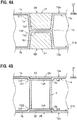
- the connecting member 2 is a member attached to an inside of the fuel tank body 1 when manufacturing the fuel tank body 1, and is formed of, for example, a thermoplastic resin. As shown in FIG. 4B , the connecting member 2 has a cylindrical shape, and includes an upper end portion 2a welded to an inner wall surface 11a of the upper wall portion 1a and a lower end portion 2b welded to an inner wall surface 11b of the lower wall portion 1b.
- the connecting member 2 is a reinforcing member for partially connecting the opposed inner wall surfaces 11a, 11b.
- two connecting members 2 are arranged inside the fuel tank body 1 with a space therebetween.
- the reinforcing member 3 is a member which is inserted from outside of the fuel tank body 1 and attached thereto when manufacturing the fuel tank body 1. It is preferred that the reinforcing member 3 is lightweight and is a member capable of increasing rigidity of the fuel tank body 1. In the present embodiment, the reinforcing member 3 is formed of an aluminum alloy. The reinforcing member 3 may be formed by welding, but in the present embodiment, it is integrally formed by die casting.
- the reinforcing members 3 are arranged in pairs on the upper wall portion 1a and the lower wall portion 1b which are opposed to each other.
- An upper reinforcing member 3A has a shape along the outer wall surface 12a of the upper wall portion 1a
- a lower reinforcing member 3B has a shape along an outer wall surface 12b of the lower wall portion 1b. Since the reinforcing member 3A and the reinforcing member 3B have common portions, the upper reinforcing member 3A will be described below with reference to FIG. 3 and the like, and then the lower reinforcing member 3B will be described.
- the reinforcing member 3A includes a first base portion 31, a second base portion 32 and a third base portion 33 which are different in shape from each other, and extending portions 34 to 38 extending along the outer wall surface 12a.
- the first base portion 31 is disposed at a substantially central portion in a left-right direction on a front side of the fuel tank body 1 (see FIGS. 1, 2 ).
- the first base portion 31 has a substantially truncated cone shape reduced in diameter downward.
- the extending portion 34 extending rightward and the extending portion 35 extending leftward are connected to the first base portion 31.
- the first base portion 31 of the reinforcing member 3A is integrated with a first projecting portion 111 projecting inwardly of the upper wall portion 1a. Since the first base portion 31 and the first projecting portion 111 are integrated together, a peripheral wall portion 1a1 and a bottom portion 1a2 of the first projecting portion 111 have a shape along a shape of the first base portion 31.
- the second base portion 32 of the reinforcing member 3A has a circular flat plate shape.
- the second base portions 32 are arranged one by one on a left side and a right side of the first base portion 31, which positions correspond to the connecting members 2, 2.
- the second base portion 32 on the left side is connected to the first base portion 31 via the extending portion 35.
- an extending portion 36 extending rearwardly, an extending portion 37 extending leftwardly, and an extending portion 38 extending forwardly are connected to the second base portion 32 on the right side.
- the second base portion 32 on the right side is connected to the first base portion 31 via the extending portion 34.
- an extending portion 36 extending rearwardly, an extending portion 37 extending rightwardly, and an extending portion 38 extending forwardly are connected.
- the second base portion 32 of the reinforcing member 3A is integrated with a second projecting portion 121 projecting inwardly of the upper wall portion 1a. Since the second base portion 32 and the second projecting portion 121 are integrated together, a step portion 1a3 and a bottom portion 1a4 of the second projecting portion 121 have a concave shape along a shape of the second base portion 32.
- the upper end portion 2a of the connecting member 2 is welded to a lower surface (the inner wall surface 11a of the upper wall portion 1a) of the bottom portion 1a4 of the second projecting portion 121.
- the third base portions 33 are arranged one by one on the left side and the right side on a rear side of the fuel tank body 1.
- the third base portion 33 has a substantially truncated cone shape reduced in diameter downward.
- the third base portion 33 on the left side is connected to the second base portion 32 on the left side via the extending portion 36.
- the third base portion 33 on the right side is connected to the second base portion 32 on the right side via the extending portion 36.
- the third base portion 33 is integrated with a third projecting portion 131 projecting inwardly of the upper wall portion 1a. Since the third base portion 33 and the third projecting portion 131 are integrated together, a peripheral wall portion 1a5 and a bottom portion 1a6 of the third projecting portion 131 have a shape along a shape of the third base portion 33.
- the third projecting portion 131 faces a fourth projecting portion 141 projecting inwardly of the lower wall portion 1b.
- the fourth projecting portion 141 includes a step portion 1b5 and a bottom portion 1b6. A lower surface of the bottom portion 1a6 of the third projecting portion 131 abuts and is welded to an upper surface of the bottom portion 1b6 of the fourth projecting portion 141.
- the extending portion 35 connects the first base portion 31 and the second base portion 32 on the left side.
- the extending portion 35 includes a projecting portion 35a projecting inwardly (downwardly) of the fuel tank body 1.
- a hole portion 35b having a substantially trapezoidal cross-section is formed inside the projecting portion 35a.
- the extending portion 35 is integrated with a fifth projecting portion 151 projecting inwardly of the upper wall portion 1a. Since the extending portion 35 and the fifth projecting portion 151 are integrated together, the fifth projecting portion 151 has a shape along a shape of the extending portion 35.
- the fifth projecting portion 151 includes a bottom portion 15a and a wall portion 15b along the shape of the extending portion 35. During molding described below, resin enters the hole portion 35b of the extending portion 35, so that the wall portion 15b is formed.
- the extending portion 34 connects the first base portion 31 and the second base portion 32 on the right side.
- the extending portion 34 includes a projecting portion 34a projecting inwardly (downwardly) of the fuel tank body 1.
- a hole portion 34b having a substantially rectangular cross-section is formed inside the projecting portion 34a.
- Two hole portions 34b are arranged side by side in an extending direction of the extending portion 34.
- the extending portion 34 is integrated with a fifth projecting portion 151 projecting inwardly of the upper wall portion 1a (see FIG. 5B ). That is, the fifth projecting portion 151 includes a bottom portion 15a and a wall portion 15b along a shape of the extending portion 34.
- resin enters the hole portions 34b of the extending portion 34, so that the wall portion 15b is formed.
- the extending portion 36 connects the second base portion 32 and the third base portion 33 respectively at the left side and the right side of the fuel tank body 1.
- the extending portion 36 has a flat plate shape.
- the extending portions 37 are respectively connected to the second base portion 32 on the left side and the second base portion 32 on the right side of the fuel tank body 1.
- the extending portion 37 includes a projecting portion 37a projecting inwardly (downwardly) of the fuel tank body 1.
- a hole portion 37b having a substantially rectangular cross-section is formed in the projecting portion 37a.
- the extending portion 37 is integrated with a projecting portion (not shown) projecting inwardly of the upper wall portion 1a.
- resin is fixed along a shape of the projecting portion 37a and enters the hole portion 37b, so that the projecting portion is formed.
- the extending portions 38 are respectively connected to the second base portion 32 on the left side and the second base portion 32 on the right side of the fuel tank body 1.
- the extending portion 38 includes a plate-like projecting portion 38a connected to the second base portion 32 and a transverse plate portion 38b provided at a distal end portion of the projecting portion 38a.
- the transverse plate portion 38b is formed wider than a plate thickness of the projecting portion 38a.
- the extending portions 38, 38 extend to positions corresponding to the cushioning members 38A, 38A. That is, the cushioning member 38A is disposed on the transverse plate portion 38b of the extending portion 38.
- the reinforcing member 3B includes a first base portion 31, second base portions 32, 32, and extending portions 34, 35.
- the first base portion 31, the second base portions 32, 32, and the extending portions 34, 35 of the reinforcing member 3B are respectively formed substantially similarly to the portions of the reinforcing member 3A, and the reinforcing member 3B is disposed vertically symmetrical with the reinforcing member 3A.
- the first base portion 31 has a substantially truncated cone shape reduced in diameter upward, and faces the first base portion 31 of the reinforcing member 3A.
- the first base portion 31 of the reinforcing member 3B includes an extending portion 34 and an extending portion 35.
- the first base portion 31 of the reinforcing member 3B is integrated with a second projecting portion 112 projecting inwardly of the lower wall portion 1b. Since the first base portion 31 and the second projecting portion 112 are integrated together, a peripheral wall portion 1b1 and a bottom portion 1b2 of the second projecting portion 112 have a shape along a shape of the first base portion 31. The bottom portion 1a2 of the first projecting portion 111 and the bottom portion 1b2 of the second projecting portion 112 abut each other to be fixed by welding.
- the second base portions 32, 32 of the reinforcing member 3B are disposed at positions corresponding to the connecting member 2, 2.
- the second base portion 32 on the left side is connected to the first base portion 31 via the extending portion 35
- the second base portion 32 on the right side is connected to the first base portion 31 via the extending portion 34.
- the reinforcing member 3B does not have the above-described extending portions 36 to 38, these extending portions 36 to 38 may be provided in the second base portion 32.
- the second base portion 32 of the reinforcing member 3B is integrated with a second projecting portion 122 projecting inwardly of the lower wall portion 1b. Since the second base portion 32 and the second projecting portion 122 are integrated together, a step portion 1b3 and a bottom portion 1b4 of the second projecting portion 122 have a concave shape along a shape of the second base portion 32.
- the lower end portion 2b of the connecting member 2 is welded to an upper surface (the inner wall surface 11b of the lower wall portion 1b) of the bottom portion 1b4 of the second projecting portion 122.
- the extending portion 35 of the reinforcing member 3B is integrated with a fifth projecting portion 151 projecting inwardly of the lower wall portion 1b.
- a tip end (lower end) of the fifth projecting portion 151 on the upper wall portion 1a side and a tip end (upper end) of the fifth projecting portion 151 on the lower wall portion 1b side are welded together.
- the extending portion 34 of the reinforcing member 3B is integrated with the fifth projecting portion 151 projecting inwardly of the lower wall portion 1b.
- the tip end (lower end) of the fifth projecting portion 151 on the upper wall portion 1a side and the tip end (upper end) of the fifth projecting portion 151 on the lower wall portion 1b side are welded together.
- the extending portions 34 and the extending portions 35 of the reinforcing members 3A, 3B vertically abut each other to be welded, the rigidity of the fuel tank body 1 can be further increased and a function of cancelling wave can be obtained.
- FIGS. 6A to 6D are schematic plan cross-sectional views showing a manufacturing procedure.
- FIG. 6A is a view showing a pair of molding dies 50a, 50b for manufacturing the fuel tank T, and corresponds to a state viewed from a direction of an arrow X shown in FIG 2 (the reinforcing members 3A, 3B are shown in cross-section).
- FIG. 6B is a view showing a parison disposed between the molding dies
- FIG. 6C is a view showing a state in which the molding dies are mold-clamped.
- FIG. 6D is a view showing a state in which a molded article of the fuel tank is taken out from the molding dies.
- a method of manufacturing the fuel tank T includes a preparation step, a parison placement step, a suction step, a connecting member attaching step, a blowing step, and a demolding step.
- the reinforcing member 3A is held by one molding die 50a and the reinforcing member 3B is held by the other molding die 50b.
- the molding dies 50a, 50b are combined together to form the fuel tank T.
- a concave portion of the molding die 50a and a concave portion of the molding die 50b are arranged to face each other.
- the molding die 50b is provided with a projecting portion 50b1 for forming the fourth projecting portion 141.
- the preparation step is a step of setting the reinforcing member 3A in the molding die 50a and setting the reinforcing member 3B in the molding die 50b.
- the molding die 50a has a holding means (not shown) for holding the reinforcing member 3A
- the molding die 50b has a holding means (not shown) for holding the reinforcing member 3B.
- a surface of the reinforcing member 3A makes surface contact with a molding surface of the molding die 50a.
- a surface of the reinforcing member 3B makes surface contact with a molding surface of the molding die 50b.
- the holding means may be configured such that magnets are provided in the molding dies 50a, 50b, or convex portions are provided in the molding dies 50a, 50b to be fitted into concave portions provided in the reinforcing members 3A, 3B.
- the parison placement step is a step of placing a parison between the molding dies 50a, 50b. As shown in FIG. 6B , in the parison placement step, a parison 61 and a parison 62 are disposed between the molding dies 50a, 50b by using a chuck (not shown) or the like.
- the reinforcing member 3A is disposed outside one parison 61 and the reinforcing member 3B is disposed outside the other parison 62.
- the suction step is a step of transferring the parisons 61, 62 to the molding dies 50a, 50b by suction.
- the connecting member attaching step is a step of attaching the connecting members 2, 2 to the parisons 61, 62 transferred to the molding dies 50a, 50b.
- the connecting member attaching step for example, the upper end portions of the connecting members 2, 2 are pushed into and attached to the parison 61 by using an attaching means such as a robot arm.
- a method of attaching the connecting member 2 is not particularly limited thereto, and for example, a center mold (not shown) may be placed between the molding dies 50a, 50b, and the connecting member 2 may be attached to the parison 61 (or the parison 62) by using the center mold.
- the molding dies 50a, 50b are moved in a facing direction and mold-clamped. Air is blown into the molding dies 50a, 50b by a blowing means (not shown), so that the parisons 61, 62 is completely transferred to the molding dies 50a, 50b.
- the parison 61 is transferred along an outer periphery of the reinforcing member 3A, and the parison 61 enters the hole portions 34b, 35b.
- the parison 62 is transferred along outer peripheries of the reinforcing member 3B and the projecting portion 50b1, and the parison 62 enters the hole portions 34b, 35b.
- the connecting member 2 is welded to the parisons 61,62.
- the demolding step is a step of taking out transferred parisons 61, 62 from the molding dies 50a, 50b. As shown in FIG. 6D , in the demolding step, the molding dies 50a, 50b are opened to take out the molded article, and burrs projecting from upper and lower ends of the molded article are cut off. Then, as shown in FIG. 1 , the pump mounting hole 1d is opened on an upper surface of the molded article, so that the fuel tank T is completed.
- the rigidity of the fuel tank body 1 can be increased.
- the second base portions 32, 32 of the reinforcing members 3A, 3B are arranged outside the connecting member 2, and the extending portions 34, 35, 36, 37, 38 extending from the second base portions 32, 32 are also arranged outside the connecting member 2.
- Two connecting members 2 are arranged, and two pairs of second base portions 32 are arranged corresponding to the two connecting members 2. This makes it possible to increase the rigidity of the fuel tank body 1 as compared with a case where the connecting member 2 and the second base portion 32 are arranged one by one. Therefore, deformation of the fuel tank body 1 can be suppressed more effectively.
- the first base portion 31 and the second base portion 32 are connected via the extending portions 34, 35, deformation between the first base portion 31 and the second base portion 32 can be suitably suppressed by the extending portions 34, 35.
- the second base portion 32 and the third base portion 33 are connected by the extending portion 36, deformation between the second base portion 32 and the third base portion 33 can be suitably suppressed by the extending portion 36.
- the first base portion 31 and the third base portion 33 may be connected by using an extending portion (not shown).
- the third base portions 33 may be connected to each other by using an extending portion (not shown).
- the extending portions 34, 35, 37, 38 respectively include projecting portions 34a, 35a, 37a, 38a.
- the inner wall surfaces 11a, 11b of the fuel tank body 1 project inwardly, it is possible to obtain the function of cancelling wave of the fuel. Further, rigidity of the reinforcing members 3A, 3B themselves is also increased. Furthermore, by transferring the parisons 61, 62 along a shape of the reinforcing members 3A, 3B during molding, the reinforcing members 3A, 3B and the fuel tank body 1 can be firmly integrated together.
- the extending portion 38 extends to a position corresponding to the cushioning member 38A, rigidity around the cushioning member 38A which is easily subjected to external forces can be increased. Therefore, deformation of the fuel tank body 1 can be suppressed more effectively.
- the projecting portion 38a is disposed perpendicular to the transverse plate portion 38b, rigidity of the extending portion 38 can be increased.
- the reinforcing members 3A, 3B are arranged in pairs on the opposed outer wall surfaces 12a, 12b of the fuel tank body 1, it is possible to increase the rigidity of the fuel tank body 1 in a well-balanced manner.
- the fuel tank body may shake inside the frame member due to, for example, a molding error between the fuel tank body and the frame member.
- the reinforcing members 3A, 3B are inserted from outside the fuel tank body 1, it is possible to firmly fix the fuel tank body 1 without shaking.
- an assembling step of assembling the frame member to the fuel tank body is required in addition to a molding step of the fuel tank body.
- the reinforcing members 3A, 3B can be inserted to the fuel tank body 1 during molding the fuel tank body 1, and thus a manufacturing cycle can be shortened.
- the reinforcing members 3A, 3B can be inserted into the fuel tank body 1, the outer wall surfaces 12a, 12b of the fuel tank body 1 and outer surfaces of the reinforcing members 3A, 3B can be flush with each other.
- the first base portion 31 of the reinforcing member 3A and the first base portion 31 of the reinforcing member 3B abut each other, and the first projecting portions 111, 112 are welded together, so that an abutment portion 115 is formed. That is, the inner wall surfaces 11a, 11b of the fuel tank body 1 can be connected to each other by the first projecting portion 111 and the second projecting portion 112. Thus, it is possible to further increase the rigidity of the fuel tank body 1 and to obtain the function of cancelling wave.
- an abutment portion 115 is formed by welding the third projecting portion 131 and the fourth projecting portion 141 by the third base portion 33 of the reinforcing member 3A. That is, the inner wall surfaces 11a, 11b of the fuel tank body 1 can be connected to each other by the third projecting portion 131 and the fourth projecting portion 141. Thus, it is possible to further increase the rigidity of the fuel tank body 1 and to obtain the function of cancelling wave.
- the reinforcing member 3 has the first base portion 31 and the third base portion 33 disposed at positions corresponding to the abutment portions 115, and the extending portions 34 to 36 extending along the outer wall surfaces 12a, 12b from the first base portion 31 and the third base portion 33, and thus the rigidity of the fuel tank body 1 can be further increased similarly to the second base portion 32 described above. Therefore, it is possible to suppress deformation of the fuel tank body 1 regardless of positive pressure deformation or negative pressure deformation of the fuel tank body 1.
- both of the connecting member 2 and the abutment portion 115 are provided, but at least one of them may be provided.
- the present invention is not limited to the above-described embodiments, and for example, various modifications can be made as follows.
- the present invention is not limited thereto, but only a part of them may be connected to each other, or they may not be connected at all.
- first base portion 31 and the third base portion 33 have a substantially truncated cone shape and the second base portion 32 has a circular flat plate shape, the present invention is not limited thereto, but they may have various shapes.
- the reinforcing member 3 includes the pair of reinforcing members 3A and 3B, the present invention is not limited thereto, but the reinforcing member 3 may include only one of them.
- the pair of reinforcing members 3A and 3B may be vertically symmetrical (an upper half and a lower half thereof may have the same shape).
Description
- The present invention relates to a fuel tank.
- As a fuel tank mounted on an automobile, one described in
Patent Document 1 is known. -
Patent Document 1 describes the fuel tank in which a frame member is provided on an outer peripheral surface of a resin fuel tank body. With this fuel tank, it is possible to reinforce the fuel tank by the frame member. - [Patent Document 1]
German Patent Application Publication No.DE102009039888A1 - The fuel tank undergoes positive pressure deformation or negative pressure deformation by internal pressure changes caused by, for example, outside air temperature changes or temperature changes due to heat of an exhaust system. Especially in case of a resin fuel tank, it is susceptible to such external factors. In the fuel tank of
Patent Document 1, although positive pressure deformation of the fuel tank body can be suppressed by the frame member, there has been a problem that negative pressure deformation cannot be dealt with. When the fuel tank body undergoes negative pressure deformation, there is a problem that a valve, a pump and the like arranged inside the fuel tank body are adversely affected. Further, in the fuel tank ofPatent Document 1, since the frame member entirely surrounds the fuel tank body from a periphery thereof, the frame member is large, and it is hard to say that deformation of the fuel tank body is effectively suppressed. - The present invention has been made in order to solve the above problems, and an object of the present invention is to provide a fuel tank capable of increasing rigidity of the fuel tank body and effectively suppressing deformation of the fuel tank body.
-
EP 1128123 discloses a storage container with an outer and at least one inner container, wherein there is an insulation space between the outer and inner containers. -
EP 2537696 discloses a fuel reservoir having internal rigid reinforcement armatures for supporting an outer shell. -
US 6294127 discloses a container assembly formed of a thermoplastic material and having a reinforcement member molded to at least one corner of the container. - A fuel tank according to an aspect of the present invention includes a resin fuel tank body including an upper wall portion, a lower wall portion, and a side wall portion connecting the upper wall portion and the lower wall portion; and a reinforcing member integrally provided on an outer wall surface of the fuel tank body, the reinforcing member being a member which is inserted from outside the fuel tank body and attached thereto when manufacturing the fuel tank body, the reinforcing member reinforcing the outer wall surface, characterized in that: the fuel tank further comprises a connecting member for partially connecting opposed inner wall surfaces of the fuel tank body, the connecting member having a cylindrical shape and including an upper end portion welded to the inner wall surface of the upper wall portion and a lower end portion welded to the inner wall surface of the lower wall portion; and/or an abutment portion where the opposed inner wall surfaces of the upper wall portion and the lower wall portion of the fuel tank body partially abut each other, wherein the abutment portion is formed by welding a first projecting portion projecting inwardly of the upper wall portion and a second projecting portion projecting inwardly of the lower wall portion together, and wherein a bottom portion of the first projecting portion and a bottom portion of the second projecting portion abut each other, and in that the reinforcing member comprises: a base portion disposed at a position corresponding to the connecting member and/or the abutment portion; and an extending portion extending along the outer wall surface of the fuel tank body from the base portion, so as to suppress positive pressure deformation and negative pressure deformation of the fuel tank body.
- According to the aspect of the present invention, since the opposed inner wall surfaces are partially connected to each other by the connecting member and/or since the opposed inner wall surfaces partially abut each other in the abutment portion, rigidity of the fuel tank body can be increased. Further, the base portion of the reinforcing member is disposed outside of the abutment portion and/or the connecting member, and the reinforcing member includes the extending portion extending from the base portion. Thus, it is possible to effectively reinforce a portion where stress is applied during positive pressure deformation or negative pressure deformation, thereby further increasing the rigidity of the fuel tank body. Therefore, regardless of positive pressure deformation or negative pressure deformation of the fuel tank body, deformation of the fuel tank body can be effectively suppressed.
- It is preferred that the connecting member and/or the abutment portion is/are arranged in plurality, the base portion is arranged in plurality corresponding to the connecting members and/or the abutment portions, and at least two of the base portions are connected to each other via the extending portion.
- With such a structure, since the rigidity of the fuel tank body can be increased as compared with a case where the connecting member and/or the abutment portion and the base portion corresponding thereto are arranged one by one, deformation of the fuel tank body can be further suppressed. In addition, since at least two of the base portions are connected to each other via the extending portion, deformation between the base portions can be suitably suppressed by the extending portion.
- The extending portion preferably includes a projecting portion projecting inwardly of the fuel tank body. With such a structure, since the inner wall surface of the fuel tank body projects inwardly of the fuel tank body, it is possible to obtain a function of cancelling wave of fuel. In addition, rigidity of the reinforcing member itself is also increased.
- It is preferred that the outer wall surface of the fuel tank body is provided with a cushioning member, and the extending portion extends to a position corresponding to the cushioning member.
- With such a structure, since rigidity around the cushioning member which is easily subjected to external forces can be increased, deformation of the fuel tank body can be more effectively suppressed.
- The reinforcing members are preferably arranged in pairs on the outer wall surfaces facing each other of the fuel tank body. With such a structure, the rigidity of the fuel tank body can be increased in a well-balanced manner.
- According to the fuel tank of the present invention, it is possible to effectively suppress deformation of the fuel tank body.
-
-
FIG. 1 is a perspective view showing a fuel tank according to an embodiment of the present invention; -
FIG. 2 is a transparent perspective view showing an interior of the fuel tank according to the embodiment of the present invention; -
FIG 3 is an exploded perspective view showing a correspondence relationship between a connecting member and a pair of upper and lower reinforcing members; -
FIG. 4A is a cross-sectional view taken along a line A-A inFIG. 2 ; -
FIG. 4B is a cross-sectional view taken along a line B-B inFIG. 2 ; -
FIG. 5A is a cross-sectional view taken along a line C-C inFIG 2 ; -
FIG. 5B is a cross-sectional view taken along a line D-D inFIG. 2 ; and -
FIGS. 6A to 6D are explanatory views showing a method of assembling the connecting member and the reinforcing member. - Hereinafter, embodiments of the present invention will be described with reference to the drawings. In the following description, when referring to "front and rear", "left and right", and "up and down", directions shown in
FIGS. 1 to 3 are used as a reference. The directions are set for convenience in describing a fuel tank T and are not intended to limit directions when the fuel tank T is mounted on the vehicle. - The fuel tank T shown in
FIGS. 1 ,2 is to be mounted on transport means such as an automobile, a motorcycle or a ship, and includes afuel tank body 1, a connecting member 2 (seeFIG. 2 ) disposed inside thefuel tank body 1, and a reinforcingmember 3 disposed outside thefuel tank body 1. - The
fuel tank body 1 is a hollow container for storing fuel such as gasoline and is formed of, for example, a thermoplastic resin including a barrier layer. Thefuel tank body 1 is manufactured by blow molding or the like. As shown inFIG. 1 , thefuel tank body 1 includes anupper wall portion 1a, alower wall portion 1b, and aside wall portion 1c connecting theupper wall portion 1a and thelower wall portion 1b. Thefuel tank body 1 is wide and has a thin shape in an up-down direction. Apump mounting hole 1d is formed through theupper wall portion 1a of thefuel tank body 1. Thepump mounting hole 1d is mounted with a pump (not shown) for pumping the fuel out of the tank. - As shown in
FIG. 1 ,cushioning members outer wall surface 12a of theupper wall portion 1a of thefuel tank body 1. Thecushioning members member 38A is formed of, for example, a material such as rubber capable of absorbing impact. - The connecting
member 2 is a member attached to an inside of thefuel tank body 1 when manufacturing thefuel tank body 1, and is formed of, for example, a thermoplastic resin. As shown inFIG. 4B , the connectingmember 2 has a cylindrical shape, and includes anupper end portion 2a welded to aninner wall surface 11a of theupper wall portion 1a and alower end portion 2b welded to aninner wall surface 11b of thelower wall portion 1b. The connectingmember 2 is a reinforcing member for partially connecting the opposedinner wall surfaces FIG. 2 , in the present embodiment, two connectingmembers 2 are arranged inside thefuel tank body 1 with a space therebetween. - As shown in
FIGS. 2 and3 , the reinforcingmember 3 is a member which is inserted from outside of thefuel tank body 1 and attached thereto when manufacturing thefuel tank body 1. It is preferred that the reinforcingmember 3 is lightweight and is a member capable of increasing rigidity of thefuel tank body 1. In the present embodiment, the reinforcingmember 3 is formed of an aluminum alloy. The reinforcingmember 3 may be formed by welding, but in the present embodiment, it is integrally formed by die casting. - The reinforcing
members 3 are arranged in pairs on theupper wall portion 1a and thelower wall portion 1b which are opposed to each other. An upper reinforcingmember 3A has a shape along theouter wall surface 12a of theupper wall portion 1a, and a lower reinforcingmember 3B has a shape along anouter wall surface 12b of thelower wall portion 1b. Since the reinforcingmember 3A and the reinforcingmember 3B have common portions, the upper reinforcingmember 3A will be described below with reference toFIG. 3 and the like, and then the lower reinforcingmember 3B will be described. - The reinforcing
member 3A includes afirst base portion 31, asecond base portion 32 and athird base portion 33 which are different in shape from each other, and extendingportions 34 to 38 extending along theouter wall surface 12a. Thefirst base portion 31 is disposed at a substantially central portion in a left-right direction on a front side of the fuel tank body 1 (seeFIGS. 1, 2 ). Thefirst base portion 31 has a substantially truncated cone shape reduced in diameter downward. The extendingportion 34 extending rightward and the extendingportion 35 extending leftward are connected to thefirst base portion 31. - As shown in
FIG. 4A , thefirst base portion 31 of the reinforcingmember 3A is integrated with a first projectingportion 111 projecting inwardly of theupper wall portion 1a. Since thefirst base portion 31 and the first projectingportion 111 are integrated together, a peripheral wall portion 1a1 and a bottom portion 1a2 of the first projectingportion 111 have a shape along a shape of thefirst base portion 31. - The
second base portion 32 of the reinforcingmember 3A has a circular flat plate shape. Thesecond base portions 32 are arranged one by one on a left side and a right side of thefirst base portion 31, which positions correspond to the connectingmembers second base portion 32 on the left side is connected to thefirst base portion 31 via the extendingportion 35. To thesecond base portion 32 on the left side, an extendingportion 36 extending rearwardly, an extendingportion 37 extending leftwardly, and an extendingportion 38 extending forwardly are connected. Thesecond base portion 32 on the right side is connected to thefirst base portion 31 via the extendingportion 34. Similarly to thesecond base portion 32 on the left side, to thesecond base portion 32 on the right side, an extendingportion 36 extending rearwardly, an extendingportion 37 extending rightwardly, and an extendingportion 38 extending forwardly are connected. - As shown in
FIG. 4B , thesecond base portion 32 of the reinforcingmember 3A is integrated with a second projectingportion 121 projecting inwardly of theupper wall portion 1a. Since thesecond base portion 32 and the second projectingportion 121 are integrated together, a step portion 1a3 and a bottom portion 1a4 of the second projectingportion 121 have a concave shape along a shape of thesecond base portion 32. Theupper end portion 2a of the connectingmember 2 is welded to a lower surface (theinner wall surface 11a of theupper wall portion 1a) of the bottom portion 1a4 of the second projectingportion 121. - As shown in
FIG. 2 , thethird base portions 33 are arranged one by one on the left side and the right side on a rear side of thefuel tank body 1. Thethird base portion 33 has a substantially truncated cone shape reduced in diameter downward. Thethird base portion 33 on the left side is connected to thesecond base portion 32 on the left side via the extendingportion 36. Thethird base portion 33 on the right side is connected to thesecond base portion 32 on the right side via the extendingportion 36. - As shown in
FIG. 5A , thethird base portion 33 is integrated with a third projectingportion 131 projecting inwardly of theupper wall portion 1a. Since thethird base portion 33 and the third projectingportion 131 are integrated together, a peripheral wall portion 1a5 and a bottom portion 1a6 of the third projectingportion 131 have a shape along a shape of thethird base portion 33. The third projectingportion 131 faces a fourth projectingportion 141 projecting inwardly of thelower wall portion 1b. The fourth projectingportion 141 includes a step portion 1b5 and a bottom portion 1b6. A lower surface of the bottom portion 1a6 of the third projectingportion 131 abuts and is welded to an upper surface of the bottom portion 1b6 of the fourth projectingportion 141. - As shown in
FIGS. 2 ,3 , the extendingportion 35 connects thefirst base portion 31 and thesecond base portion 32 on the left side. The extendingportion 35 includes a projectingportion 35a projecting inwardly (downwardly) of thefuel tank body 1. Ahole portion 35b having a substantially trapezoidal cross-section is formed inside the projectingportion 35a. As shown inFIG. 5B , the extendingportion 35 is integrated with a fifth projectingportion 151 projecting inwardly of theupper wall portion 1a. Since the extendingportion 35 and the fifth projectingportion 151 are integrated together, the fifth projectingportion 151 has a shape along a shape of the extendingportion 35. That is, the fifth projectingportion 151 includes abottom portion 15a and awall portion 15b along the shape of the extendingportion 35. During molding described below, resin enters thehole portion 35b of the extendingportion 35, so that thewall portion 15b is formed. - As shown in
FIG. 2 ,3 , the extendingportion 34 connects thefirst base portion 31 and thesecond base portion 32 on the right side. The extendingportion 34 includes a projectingportion 34a projecting inwardly (downwardly) of thefuel tank body 1. Ahole portion 34b having a substantially rectangular cross-section is formed inside the projectingportion 34a. Twohole portions 34b are arranged side by side in an extending direction of the extendingportion 34. Similarly to the extendingportion 35 described above, the extendingportion 34 is integrated with a fifth projectingportion 151 projecting inwardly of theupper wall portion 1a (seeFIG. 5B ). That is, the fifth projectingportion 151 includes abottom portion 15a and awall portion 15b along a shape of the extendingportion 34. During molding described below, resin enters thehole portions 34b of the extendingportion 34, so that thewall portion 15b is formed. - The extending
portion 36 connects thesecond base portion 32 and thethird base portion 33 respectively at the left side and the right side of thefuel tank body 1. The extendingportion 36 has a flat plate shape. - As shown in
FIG. 3 , the extendingportions 37 are respectively connected to thesecond base portion 32 on the left side and thesecond base portion 32 on the right side of thefuel tank body 1. The extendingportion 37 includes a projectingportion 37a projecting inwardly (downwardly) of thefuel tank body 1. Ahole portion 37b having a substantially rectangular cross-section is formed in the projectingportion 37a. The extendingportion 37 is integrated with a projecting portion (not shown) projecting inwardly of theupper wall portion 1a. Similarly to the fifth projectingportion 151 described above, during molding, resin is fixed along a shape of the projectingportion 37a and enters thehole portion 37b, so that the projecting portion is formed. - The extending
portions 38 are respectively connected to thesecond base portion 32 on the left side and thesecond base portion 32 on the right side of thefuel tank body 1. The extendingportion 38 includes a plate-like projectingportion 38a connected to thesecond base portion 32 and atransverse plate portion 38b provided at a distal end portion of the projectingportion 38a. Thetransverse plate portion 38b is formed wider than a plate thickness of the projectingportion 38a. As shown inFIG. 1 , the extendingportions cushioning members member 38A is disposed on thetransverse plate portion 38b of the extendingportion 38. - The reinforcing
member 3B includes afirst base portion 31,second base portions portions first base portion 31, thesecond base portions portions member 3B are respectively formed substantially similarly to the portions of the reinforcingmember 3A, and the reinforcingmember 3B is disposed vertically symmetrical with the reinforcingmember 3A. - In the reinforcing
member 3B, thefirst base portion 31 has a substantially truncated cone shape reduced in diameter upward, and faces thefirst base portion 31 of the reinforcingmember 3A. Similarly to thefirst base portion 31 of the reinforcingmember 3A, thefirst base portion 31 of the reinforcingmember 3B includes an extendingportion 34 and an extendingportion 35. - As shown in
FIG. 4A , thefirst base portion 31 of the reinforcingmember 3B is integrated with a second projectingportion 112 projecting inwardly of thelower wall portion 1b. Since thefirst base portion 31 and the second projectingportion 112 are integrated together, a peripheral wall portion 1b1 and a bottom portion 1b2 of the second projectingportion 112 have a shape along a shape of thefirst base portion 31. The bottom portion 1a2 of the first projectingportion 111 and the bottom portion 1b2 of the second projectingportion 112 abut each other to be fixed by welding. - As shown in
FIG. 4B , thesecond base portions member 3B are disposed at positions corresponding to the connectingmember second base portion 32 on the left side is connected to thefirst base portion 31 via the extendingportion 35, and thesecond base portion 32 on the right side is connected to thefirst base portion 31 via the extendingportion 34. Although the reinforcingmember 3B does not have the above-described extendingportions 36 to 38, these extendingportions 36 to 38 may be provided in thesecond base portion 32. - The
second base portion 32 of the reinforcingmember 3B is integrated with a second projectingportion 122 projecting inwardly of thelower wall portion 1b. Since thesecond base portion 32 and the second projectingportion 122 are integrated together, a step portion 1b3 and a bottom portion 1b4 of the second projectingportion 122 have a concave shape along a shape of thesecond base portion 32. Thelower end portion 2b of the connectingmember 2 is welded to an upper surface (theinner wall surface 11b of thelower wall portion 1b) of the bottom portion 1b4 of the second projectingportion 122. - As shown in
FIG. 5B , the extendingportion 35 of the reinforcingmember 3B is integrated with a fifth projectingportion 151 projecting inwardly of thelower wall portion 1b. A tip end (lower end) of the fifth projectingportion 151 on theupper wall portion 1a side and a tip end (upper end) of the fifth projectingportion 151 on thelower wall portion 1b side are welded together. - Similarly to the extending
portion 35, the extendingportion 34 of the reinforcingmember 3B is integrated with the fifth projectingportion 151 projecting inwardly of thelower wall portion 1b. The tip end (lower end) of the fifth projectingportion 151 on theupper wall portion 1a side and the tip end (upper end) of the fifth projectingportion 151 on thelower wall portion 1b side are welded together. In this way, since the extendingportions 34 and the extendingportions 35 of the reinforcingmembers fuel tank body 1 can be further increased and a function of cancelling wave can be obtained. - Next, a manufacturing procedure of the fuel tank T will be described with reference to
FIGS. 6A to 6D. FIGS. 6A to 6D are schematic plan cross-sectional views showing a manufacturing procedure.FIG. 6A is a view showing a pair of molding dies 50a, 50b for manufacturing the fuel tank T, and corresponds to a state viewed from a direction of an arrow X shown inFIG 2 (the reinforcingmembers FIG. 6B is a view showing a parison disposed between the molding dies, andFIG. 6C is a view showing a state in which the molding dies are mold-clamped.FIG. 6D is a view showing a state in which a molded article of the fuel tank is taken out from the molding dies. - A method of manufacturing the fuel tank T includes a preparation step, a parison placement step, a suction step, a connecting member attaching step, a blowing step, and a demolding step. As shown in
FIG. 6A , the reinforcingmember 3A is held by one molding die 50a and the reinforcingmember 3B is held by the other molding die 50b. The molding dies 50a, 50b are combined together to form the fuel tank T. As shown in the drawings, a concave portion of the molding die 50a and a concave portion of themolding die 50b are arranged to face each other. Themolding die 50b is provided with a projecting portion 50b1 for forming the fourth projectingportion 141. - The preparation step is a step of setting the reinforcing
member 3A in the molding die 50a and setting the reinforcingmember 3B in themolding die 50b. The molding die 50a has a holding means (not shown) for holding the reinforcingmember 3A, and themolding die 50b has a holding means (not shown) for holding the reinforcingmember 3B. A surface of the reinforcingmember 3A makes surface contact with a molding surface of the molding die 50a. A surface of the reinforcingmember 3B makes surface contact with a molding surface of themolding die 50b. - By setting the reinforcing
members members members - The parison placement step is a step of placing a parison between the molding dies 50a, 50b. As shown in
FIG. 6B , in the parison placement step, aparison 61 and aparison 62 are disposed between the molding dies 50a, 50b by using a chuck (not shown) or the like. The reinforcingmember 3A is disposed outside oneparison 61 and the reinforcingmember 3B is disposed outside theother parison 62. - The suction step is a step of transferring the
parisons members parisons members parison 61 by using an attaching means such as a robot arm. A method of attaching the connectingmember 2 is not particularly limited thereto, and for example, a center mold (not shown) may be placed between the molding dies 50a, 50b, and the connectingmember 2 may be attached to the parison 61 (or the parison 62) by using the center mold. - In the blowing step, the molding dies 50a, 50b are moved in a facing direction and mold-clamped. Air is blown into the molding dies 50a, 50b by a blowing means (not shown), so that the
parisons parison 61 is transferred along an outer periphery of the reinforcingmember 3A, and theparison 61 enters thehole portions parison 62 is transferred along outer peripheries of the reinforcingmember 3B and the projecting portion 50b1, and theparison 62 enters thehole portions member 2 is welded to theparisons - The demolding step is a step of taking out transferred
parisons FIG. 6D , in the demolding step, the molding dies 50a, 50b are opened to take out the molded article, and burrs projecting from upper and lower ends of the molded article are cut off. Then, as shown inFIG. 1 , thepump mounting hole 1d is opened on an upper surface of the molded article, so that the fuel tank T is completed. - With the fuel tank T of the present embodiment described above, since the opposed
inner wall surfaces member 2, the rigidity of thefuel tank body 1 can be increased. Thesecond base portions members member 2, and the extendingportions second base portions member 2. Thus, it is possible to effectively reinforce a portion where stress is applied during positive pressure deformation or negative pressure deformation, thereby further increase the rigidity of thefuel tank body 1. Therefore, it is possible to suppress deformation of thefuel tank body 1 regardless of positive pressure deformation or negative pressure deformation of thefuel tank body 1. - Two connecting
members 2 are arranged, and two pairs ofsecond base portions 32 are arranged corresponding to the two connectingmembers 2. This makes it possible to increase the rigidity of thefuel tank body 1 as compared with a case where the connectingmember 2 and thesecond base portion 32 are arranged one by one. Therefore, deformation of thefuel tank body 1 can be suppressed more effectively. In addition, for example, since thefirst base portion 31 and thesecond base portion 32 are connected via the extendingportions first base portion 31 and thesecond base portion 32 can be suitably suppressed by the extendingportions - Since the
second base portion 32 and thethird base portion 33 are connected by the extendingportion 36, deformation between thesecond base portion 32 and thethird base portion 33 can be suitably suppressed by the extendingportion 36. In this case, thefirst base portion 31 and thethird base portion 33 may be connected by using an extending portion (not shown). Further, thethird base portions 33 may be connected to each other by using an extending portion (not shown). - The extending
portions portions inner wall surfaces fuel tank body 1 project inwardly, it is possible to obtain the function of cancelling wave of the fuel. Further, rigidity of the reinforcingmembers parisons members members fuel tank body 1 can be firmly integrated together. - Since the extending
portion 38 extends to a position corresponding to the cushioningmember 38A, rigidity around the cushioningmember 38A which is easily subjected to external forces can be increased. Therefore, deformation of thefuel tank body 1 can be suppressed more effectively. In addition, since the projectingportion 38a is disposed perpendicular to thetransverse plate portion 38b, rigidity of the extendingportion 38 can be increased. - Since the reinforcing
members outer wall surfaces fuel tank body 1, it is possible to increase the rigidity of thefuel tank body 1 in a well-balanced manner. - In the prior art, the fuel tank body may shake inside the frame member due to, for example, a molding error between the fuel tank body and the frame member. However, in the present embodiment, since the reinforcing
members fuel tank body 1, it is possible to firmly fix thefuel tank body 1 without shaking. Further, in the prior art, an assembling step of assembling the frame member to the fuel tank body is required in addition to a molding step of the fuel tank body. In contrast, in the present embodiment, the reinforcingmembers fuel tank body 1 during molding thefuel tank body 1, and thus a manufacturing cycle can be shortened. In addition, since the reinforcingmembers fuel tank body 1, theouter wall surfaces fuel tank body 1 and outer surfaces of the reinforcingmembers - In the present embodiment, as shown in
FIG. 4A , thefirst base portion 31 of the reinforcingmember 3A and thefirst base portion 31 of the reinforcingmember 3B abut each other, and the first projectingportions abutment portion 115 is formed. That is, theinner wall surfaces fuel tank body 1 can be connected to each other by the first projectingportion 111 and the second projectingportion 112. Thus, it is possible to further increase the rigidity of thefuel tank body 1 and to obtain the function of cancelling wave. - In the present embodiment, as shown in
FIG. 5A , anabutment portion 115 is formed by welding the third projectingportion 131 and the fourth projectingportion 141 by thethird base portion 33 of the reinforcingmember 3A. That is, theinner wall surfaces fuel tank body 1 can be connected to each other by the third projectingportion 131 and the fourth projectingportion 141. Thus, it is possible to further increase the rigidity of thefuel tank body 1 and to obtain the function of cancelling wave. In addition, the reinforcingmember 3 has thefirst base portion 31 and thethird base portion 33 disposed at positions corresponding to theabutment portions 115, and the extendingportions 34 to 36 extending along theouter wall surfaces first base portion 31 and thethird base portion 33, and thus the rigidity of thefuel tank body 1 can be further increased similarly to thesecond base portion 32 described above. Therefore, it is possible to suppress deformation of thefuel tank body 1 regardless of positive pressure deformation or negative pressure deformation of thefuel tank body 1. In the present embodiment, both of the connectingmember 2 and theabutment portion 115 are provided, but at least one of them may be provided. - Although the embodiments of the present invention have been described above, the present invention is not limited to the above-described embodiments, and for example, various modifications can be made as follows. For example, in the above-described embodiment, although the
first base portion 31, thesecond base portion 32 and thethird base portion 33 are all connected by the extendingportions - Although the
first base portion 31 and thethird base portion 33 have a substantially truncated cone shape and thesecond base portion 32 has a circular flat plate shape, the present invention is not limited thereto, but they may have various shapes. - Although the reinforcing
member 3 includes the pair of reinforcingmembers member 3 may include only one of them. The pair of reinforcingmembers -
- 1:
- fuel tank body
- 2:
- connecting member
- 3:
- reinforcing member
- 3A, 3B:
- reinforcing member
- 11a, 11b:
- inner wall surface
- 12a, 12b:
- outer wall surface
- 31:
- first base portion
- 32:
- second base portion
- 33:
- third base portion
- 34 to 38:
- extending portion
- 34a, 35a:
- projecting portion
- 37a:
- projecting portion
- 38a:
- projecting portion
- 38A:
- cushioning member
- T:
- fuel tank
Claims (6)
- A fuel tank comprising:a resin fuel tank body (1) including an upper wall portion (1a), a lower wall portion (1b), and a side wall portion (lc) connecting the upper wall portion (1a) and the lower wall portion (1b); anda reinforcing member (3A, 3B) integrally provided on an outer wall surface (12a, 12b) of the fuel tank body (1), the reinforcing member (3A, 3B) being a member which is inserted from outside the fuel tank body (1) and attached thereto when manufacturing the fuel tank body (1), the reinforcing member (3A, 3B) reinforcing the outer wall surface (12a, 12b), characterized in that:the fuel tank further comprises a connecting member (2) for partially connecting opposed inner wall surfaces (11a, 11b) of the fuel tank body (1), the connecting member (2) having a cylindrical shape and including an upper end portion (2a) welded to the inner wall surface (11a) of the upper wall portion (1a) and a lower end portion (2b) welded to the inner wall surface (11b) of the lower wall portion (1b); and/oran abutment portion (115) where the opposed inner wall surfaces (11a, 11b) of the upper wall portion (1a) and the lower wall portion (1b) of the fuel tank body (1) partially abut each other, wherein the abutment portion (115) is formed by welding a first projecting portion (111, 131) projecting inwardly of the upper wall portion (1a) and a second projecting portion (112, 141) projecting inwardly of the lower wall portion (1b) together, and wherein a bottom portion (la2, la6) of the first projecting portion (111, 131) and a bottom portion (1b2, 1b6) of the second projecting portion (112, 141) abut each other, and in that the reinforcing member (3A, 3B) comprises:a base portion (31, 32, 33) disposed at a position corresponding to the connecting member (2) and/or the abutment portion (115); andan extending portion (34, 35, 36, 37, 38) extending along the outer wall surface (12a) of the fuel tank body (1) from the base portion (31, 32, 33), so as to suppress positive pressure deformation and negative pressure deformation of the fuel tank body.
- The fuel tank according to claim 1, whereinthe connecting member (2) and/or the abutment portion (115) is/are arranged in plurality,the base portion (31, 32, 33) is arranged in plurality corresponding to the connecting member (2) and/or the abutment portion (115), andat least two of the base portion (31, 32, 33) are connected to each other via the extending portion (34, 35, 36, 37, 38).
- The fuel tank according to claim 1 or 2, wherein the extending portion (34, 35, 36, 37, 38) includes a projecting portion (34a, 35a, 37a, 38a) projecting inwardly of the fuel tank body (1).
- The fuel tank according to claim 3, wherein the projecting portion (34a, 35a, 37a, 38a) includes a concave portion or a hole portion (34b, 35b, 37b).
- The fuel tank according to claim 1, whereinthe outer wall surface of the fuel tank body (1) is provided with a cushioning member (38A), andthe extending portion (34, 35, 36, 37, 38) extends to a position corresponding to the cushioning member (38A).
- The fuel tank according to claim 1, wherein the reinforcing members (3A, 3B) are arranged in pairs on the outer wall surfaces (12a, 12b) facing each other of the fuel tank body.
Applications Claiming Priority (2)
| Application Number | Priority Date | Filing Date | Title |
|---|---|---|---|
| JP2015090204 | 2015-04-27 | ||
| PCT/JP2016/057308 WO2016174936A1 (en) | 2015-04-27 | 2016-03-09 | Fuel tank |
Publications (3)
| Publication Number | Publication Date |
|---|---|
| EP3290249A1 EP3290249A1 (en) | 2018-03-07 |
| EP3290249A4 EP3290249A4 (en) | 2018-08-29 |
| EP3290249B1 true EP3290249B1 (en) | 2020-08-05 |
Family
ID=57198282
Family Applications (1)
| Application Number | Title | Priority Date | Filing Date |
|---|---|---|---|
| EP16786213.5A Active EP3290249B1 (en) | 2015-04-27 | 2016-03-09 | Fuel tank |
Country Status (5)
| Country | Link |
|---|---|
| US (1) | US10322630B2 (en) |
| EP (1) | EP3290249B1 (en) |
| JP (1) | JP6298931B2 (en) |
| CN (1) | CN107531145B (en) |
| WO (1) | WO2016174936A1 (en) |
Families Citing this family (3)
| Publication number | Priority date | Publication date | Assignee | Title |
|---|---|---|---|---|
| CN110722980A (en) * | 2018-07-17 | 2020-01-24 | 泽菲罗斯有限公司 | Structural reinforcement for fuel tank |
| KR20210055317A (en) | 2019-11-07 | 2021-05-17 | 현대자동차주식회사 | Stiffness reinforcement structure for fuel tank of vehicle |
| CN117561180A (en) * | 2021-07-26 | 2024-02-13 | 八千代工业株式会社 | Fuel tank |
Citations (1)
| Publication number | Priority date | Publication date | Assignee | Title |
|---|---|---|---|---|
| US3596794A (en) * | 1969-11-18 | 1971-08-03 | Phillips Petroleum Co | Supporting apparatus |
Family Cites Families (28)
| Publication number | Priority date | Publication date | Assignee | Title |
|---|---|---|---|---|
| US2724418A (en) * | 1953-03-02 | 1955-11-22 | Goodrich Co B F | Fluid-receiving container with volumeresponsive pressure-relief and overflow valve assembly |
| GB1573510A (en) * | 1977-01-11 | 1980-08-28 | Northern Eng Ind | Liquid storage tanks made of panels |
| IT8153149V0 (en) * | 1981-04-16 | 1981-04-16 | Fiat Auto Spa | FUEL TANK PARTICULARLY PARTLY FOR VEHICLES |
| JPS63258750A (en) * | 1987-04-16 | 1988-10-26 | 東燃化学株式会社 | Plastic tank with baffle |
| US6294127B1 (en) | 1998-05-15 | 2001-09-25 | The Moore Company | Fuel tank having molded reinforcements and method of making same |
| US6338420B1 (en) * | 1999-06-08 | 2002-01-15 | Delphi Technologies, Inc. | Motor vehicle fuel tank and method |
| DE10008985A1 (en) * | 2000-02-25 | 2001-08-30 | Linde Ag | Reservoir container for cryogenic fluids; has insulation space between inner and outer containers with reinforcement webs may be formed on walls or support plates may be welded in inner container |
| JP4014907B2 (en) * | 2002-03-27 | 2007-11-28 | 日新製鋼株式会社 | Stainless steel fuel tank and fuel pipe made of stainless steel with excellent corrosion resistance |
| DE10329990B3 (en) * | 2003-07-02 | 2005-04-21 | Benteler Automobiltechnik Gmbh | Pressure gas tank |
| JP2006192919A (en) * | 2005-01-11 | 2006-07-27 | Fts:Kk | Fuel tank for automobile and its manufacturing method |
| US7284417B2 (en) * | 2005-07-28 | 2007-10-23 | Reynolds Charles W | Tire monitor |
| JP4775080B2 (en) * | 2006-04-03 | 2011-09-21 | 日産自動車株式会社 | Fuel tank structure |
| JP2009166753A (en) | 2008-01-18 | 2009-07-30 | Yamaha Motor Co Ltd | Fuel tank, motorcycle with fuel tank, and manufacturing method for fuel tank |
| KR100967815B1 (en) * | 2008-02-26 | 2010-07-05 | 대우조선해양 주식회사 | Lng storage tank for a floating structure |
| JP4832480B2 (en) | 2008-08-08 | 2011-12-07 | 八千代工業株式会社 | Fuel tank protective plate mounting structure |
| DE102009036911B4 (en) * | 2009-08-11 | 2016-03-03 | Magna Steyr Fuel Systems Gmbh | Fuel tank for motor vehicles with tie rods |
| DE102009039888A1 (en) | 2009-09-03 | 2011-03-10 | Volkswagen Ag | Pressure container for use in vehicle, is made of plastic, and has reinforcement element, which is arranged at outer contour, where frame structure is provided, which is arranged in one or multiple constrictions of pressure container |
| DE102010036683A1 (en) * | 2010-07-28 | 2012-02-02 | Dr. Ing. H.C. F. Porsche Aktiengesellschaft | Fuel tank |
| FR2970776B1 (en) * | 2011-01-24 | 2014-05-02 | Onera (Off Nat Aerospatiale) | DEVICE FOR MEASURING THE TEMPERATURE OF A VIBRATING BEAM AND APPLICATION TO IMPROVING THE MEASUREMENT PRECISION OF A VIBRATING BEAM SENSOR |
| EP2537696B1 (en) * | 2011-06-24 | 2013-12-25 | Magna Steyr Fuel Systems GesmbH | Fuel reservoir for a motor vehicle |
| JP5646413B2 (en) * | 2011-08-24 | 2014-12-24 | 株式会社神戸製鋼所 | Pressure vessel |
| JP5750406B2 (en) * | 2012-06-20 | 2015-07-22 | 株式会社神戸製鋼所 | Pressure vessel |
| DE102012108851A1 (en) | 2012-09-20 | 2014-03-20 | Veritas Ag | Liquid tank with a baffle |
| US20140166664A1 (en) * | 2012-12-17 | 2014-06-19 | The Curators Of The University Of Missouri | Conformal Tank For Adsorbant Natural Gas Storage |
| JP2014148227A (en) * | 2013-01-31 | 2014-08-21 | Yachiyo Industry Co Ltd | Fitting structure of fuel tank to vehicle body |
| JP5932854B2 (en) * | 2013-09-18 | 2016-06-08 | トヨタ自動車株式会社 | Fuel tank |
| DE102014222145A1 (en) * | 2014-10-30 | 2016-05-19 | Volkswagen Aktiengesellschaft | Fuel tank for a motor vehicle |
| WO2016167018A1 (en) * | 2015-04-15 | 2016-10-20 | 八千代工業株式会社 | Fuel tank |
-
2016
- 2016-03-09 WO PCT/JP2016/057308 patent/WO2016174936A1/en active Application Filing
- 2016-03-09 JP JP2017515424A patent/JP6298931B2/en active Active
- 2016-03-09 CN CN201680023867.6A patent/CN107531145B/en active Active
- 2016-03-09 US US15/569,823 patent/US10322630B2/en active Active
- 2016-03-09 EP EP16786213.5A patent/EP3290249B1/en active Active
Patent Citations (1)
| Publication number | Priority date | Publication date | Assignee | Title |
|---|---|---|---|---|
| US3596794A (en) * | 1969-11-18 | 1971-08-03 | Phillips Petroleum Co | Supporting apparatus |
Also Published As
| Publication number | Publication date |
|---|---|
| CN107531145B (en) | 2019-03-15 |
| JP6298931B2 (en) | 2018-03-28 |
| US20180134150A1 (en) | 2018-05-17 |
| CN107531145A (en) | 2018-01-02 |
| US10322630B2 (en) | 2019-06-18 |
| EP3290249A4 (en) | 2018-08-29 |
| WO2016174936A1 (en) | 2016-11-03 |
| JPWO2016174936A1 (en) | 2018-02-01 |
| EP3290249A1 (en) | 2018-03-07 |
Similar Documents
| Publication | Publication Date | Title |
|---|---|---|
| EP3290249B1 (en) | Fuel tank | |
| CN105313811A (en) | Bumper structure for a motor vehicle | |
| US10208847B1 (en) | Structure of transmission mount | |
| CN104955670A (en) | Structure for mounting fuel tank on vehicle body, and device for preventing deformation of fuel tank | |
| KR20120028941A (en) | Process for reinforcing a rigid plastic fuel tank | |
| CN110691730B (en) | Storage compartment for assembly in a motor vehicle body structure and method for producing the same | |
| CN105873750A (en) | Moulding element comprising a special fastening means | |
| JP2006282099A (en) | Fiber-reinforced resin structure | |
| CN204449754U (en) | A kind of fore sub frame welding tooling | |
| US20220203788A1 (en) | Suspension arm for vehicles and method for producing same | |
| CN110696577A (en) | Metal/resin composite member | |
| JP6032293B2 (en) | Manufacturing method of resin parts for vehicles | |
| CN100463830C (en) | Suspension strut top mounting in a body structure of a motor vehicle | |
| JP6747927B2 (en) | Fuel tank | |
| US20070139940A1 (en) | Front end module carrier for vehicle | |
| US10800252B2 (en) | Resin fuel tank and blow molding mold for molding the same | |
| KR101925134B1 (en) | Motor mount bracket of plastic material | |
| EP3470253A1 (en) | Fuel tank | |
| US11478993B2 (en) | Fuel tank for a motor vehicle, and method for producing a fuel tank | |
| JP6188193B2 (en) | Method for assembling cyclic resin product and cyclic resin product | |
| CN214450271U (en) | Reinforcement for a vehicle tank and vehicle tank comprising such a reinforcement | |
| CN112823114B (en) | Engine bracket for motor vehicle | |
| KR101542553B1 (en) | hybrid carrier | |
| US20120256075A1 (en) | Method of producing split outer shell cradle mount with rate plates | |
| KR20200092808A (en) | Suspension arm for vehicle |
Legal Events
| Date | Code | Title | Description |
|---|---|---|---|
| STAA | Information on the status of an ep patent application or granted ep patent |
Free format text: STATUS: THE INTERNATIONAL PUBLICATION HAS BEEN MADE |
|
| PUAI | Public reference made under article 153(3) epc to a published international application that has entered the european phase |
Free format text: ORIGINAL CODE: 0009012 |
|
| STAA | Information on the status of an ep patent application or granted ep patent |
Free format text: STATUS: REQUEST FOR EXAMINATION WAS MADE |
|
| 17P | Request for examination filed |
Effective date: 20171027 |
|
| AK | Designated contracting states |
Kind code of ref document: A1 Designated state(s): AL AT BE BG CH CY CZ DE DK EE ES FI FR GB GR HR HU IE IS IT LI LT LU LV MC MK MT NL NO PL PT RO RS SE SI SK SM TR |
|
| AX | Request for extension of the european patent |
Extension state: BA ME |
|
| DAV | Request for validation of the european patent (deleted) | ||
| DAX | Request for extension of the european patent (deleted) | ||
| A4 | Supplementary search report drawn up and despatched |
Effective date: 20180731 |
|
| RIC1 | Information provided on ipc code assigned before grant |
Ipc: F02M 37/00 20060101ALI20180725BHEP Ipc: B29C 51/02 20060101ALI20180725BHEP Ipc: B29C 51/12 20060101ALI20180725BHEP Ipc: B60K 15/03 20060101AFI20180725BHEP Ipc: B29C 49/48 20060101ALI20180725BHEP Ipc: B29C 49/04 20060101ALI20180725BHEP Ipc: B29C 49/20 20060101ALI20180725BHEP Ipc: B29C 51/30 20060101ALI20180725BHEP |
|
| STAA | Information on the status of an ep patent application or granted ep patent |
Free format text: STATUS: EXAMINATION IS IN PROGRESS |
|
| 17Q | First examination report despatched |
Effective date: 20190405 |
|
| GRAP | Despatch of communication of intention to grant a patent |
Free format text: ORIGINAL CODE: EPIDOSNIGR1 |
|
| STAA | Information on the status of an ep patent application or granted ep patent |
Free format text: STATUS: GRANT OF PATENT IS INTENDED |
|
| INTG | Intention to grant announced |
Effective date: 20200424 |
|
| GRAS | Grant fee paid |
Free format text: ORIGINAL CODE: EPIDOSNIGR3 |
|
| GRAA | (expected) grant |
Free format text: ORIGINAL CODE: 0009210 |
|
| STAA | Information on the status of an ep patent application or granted ep patent |
Free format text: STATUS: THE PATENT HAS BEEN GRANTED |
|
| AK | Designated contracting states |
Kind code of ref document: B1 Designated state(s): AL AT BE BG CH CY CZ DE DK EE ES FI FR GB GR HR HU IE IS IT LI LT LU LV MC MK MT NL NO PL PT RO RS SE SI SK SM TR |
|
| REG | Reference to a national code |
Ref country code: GB Ref legal event code: FG4D |
|
| REG | Reference to a national code |
Ref country code: CH Ref legal event code: EP |
|
| REG | Reference to a national code |
Ref country code: AT Ref legal event code: REF Ref document number: 1298256 Country of ref document: AT Kind code of ref document: T Effective date: 20200815 |
|
| REG | Reference to a national code |
Ref country code: DE Ref legal event code: R096 Ref document number: 602016041459 Country of ref document: DE |
|
| REG | Reference to a national code |
Ref country code: IE Ref legal event code: FG4D |
|
| REG | Reference to a national code |
Ref country code: LT Ref legal event code: MG4D |
|
| REG | Reference to a national code |
Ref country code: NL Ref legal event code: MP Effective date: 20200805 |
|
| REG | Reference to a national code |
Ref country code: AT Ref legal event code: MK05 Ref document number: 1298256 Country of ref document: AT Kind code of ref document: T Effective date: 20200805 |
|
| PG25 | Lapsed in a contracting state [announced via postgrant information from national office to epo] |
Ref country code: LT Free format text: LAPSE BECAUSE OF FAILURE TO SUBMIT A TRANSLATION OF THE DESCRIPTION OR TO PAY THE FEE WITHIN THE PRESCRIBED TIME-LIMIT Effective date: 20200805 Ref country code: AT Free format text: LAPSE BECAUSE OF FAILURE TO SUBMIT A TRANSLATION OF THE DESCRIPTION OR TO PAY THE FEE WITHIN THE PRESCRIBED TIME-LIMIT Effective date: 20200805 Ref country code: HR Free format text: LAPSE BECAUSE OF FAILURE TO SUBMIT A TRANSLATION OF THE DESCRIPTION OR TO PAY THE FEE WITHIN THE PRESCRIBED TIME-LIMIT Effective date: 20200805 Ref country code: SE Free format text: LAPSE BECAUSE OF FAILURE TO SUBMIT A TRANSLATION OF THE DESCRIPTION OR TO PAY THE FEE WITHIN THE PRESCRIBED TIME-LIMIT Effective date: 20200805 Ref country code: BG Free format text: LAPSE BECAUSE OF FAILURE TO SUBMIT A TRANSLATION OF THE DESCRIPTION OR TO PAY THE FEE WITHIN THE PRESCRIBED TIME-LIMIT Effective date: 20201105 Ref country code: FI Free format text: LAPSE BECAUSE OF FAILURE TO SUBMIT A TRANSLATION OF THE DESCRIPTION OR TO PAY THE FEE WITHIN THE PRESCRIBED TIME-LIMIT Effective date: 20200805 Ref country code: NO Free format text: LAPSE BECAUSE OF FAILURE TO SUBMIT A TRANSLATION OF THE DESCRIPTION OR TO PAY THE FEE WITHIN THE PRESCRIBED TIME-LIMIT Effective date: 20201105 Ref country code: GR Free format text: LAPSE BECAUSE OF FAILURE TO SUBMIT A TRANSLATION OF THE DESCRIPTION OR TO PAY THE FEE WITHIN THE PRESCRIBED TIME-LIMIT Effective date: 20201106 Ref country code: ES Free format text: LAPSE BECAUSE OF FAILURE TO SUBMIT A TRANSLATION OF THE DESCRIPTION OR TO PAY THE FEE WITHIN THE PRESCRIBED TIME-LIMIT Effective date: 20200805 Ref country code: PT Free format text: LAPSE BECAUSE OF FAILURE TO SUBMIT A TRANSLATION OF THE DESCRIPTION OR TO PAY THE FEE WITHIN THE PRESCRIBED TIME-LIMIT Effective date: 20201207 |
|
| PG25 | Lapsed in a contracting state [announced via postgrant information from national office to epo] |
Ref country code: NL Free format text: LAPSE BECAUSE OF FAILURE TO SUBMIT A TRANSLATION OF THE DESCRIPTION OR TO PAY THE FEE WITHIN THE PRESCRIBED TIME-LIMIT Effective date: 20200805 Ref country code: RS Free format text: LAPSE BECAUSE OF FAILURE TO SUBMIT A TRANSLATION OF THE DESCRIPTION OR TO PAY THE FEE WITHIN THE PRESCRIBED TIME-LIMIT Effective date: 20200805 Ref country code: LV Free format text: LAPSE BECAUSE OF FAILURE TO SUBMIT A TRANSLATION OF THE DESCRIPTION OR TO PAY THE FEE WITHIN THE PRESCRIBED TIME-LIMIT Effective date: 20200805 Ref country code: PL Free format text: LAPSE BECAUSE OF FAILURE TO SUBMIT A TRANSLATION OF THE DESCRIPTION OR TO PAY THE FEE WITHIN THE PRESCRIBED TIME-LIMIT Effective date: 20200805 Ref country code: IS Free format text: LAPSE BECAUSE OF FAILURE TO SUBMIT A TRANSLATION OF THE DESCRIPTION OR TO PAY THE FEE WITHIN THE PRESCRIBED TIME-LIMIT Effective date: 20201205 |
|
| PG25 | Lapsed in a contracting state [announced via postgrant information from national office to epo] |
Ref country code: EE Free format text: LAPSE BECAUSE OF FAILURE TO SUBMIT A TRANSLATION OF THE DESCRIPTION OR TO PAY THE FEE WITHIN THE PRESCRIBED TIME-LIMIT Effective date: 20200805 Ref country code: SM Free format text: LAPSE BECAUSE OF FAILURE TO SUBMIT A TRANSLATION OF THE DESCRIPTION OR TO PAY THE FEE WITHIN THE PRESCRIBED TIME-LIMIT Effective date: 20200805 Ref country code: RO Free format text: LAPSE BECAUSE OF FAILURE TO SUBMIT A TRANSLATION OF THE DESCRIPTION OR TO PAY THE FEE WITHIN THE PRESCRIBED TIME-LIMIT Effective date: 20200805 Ref country code: CZ Free format text: LAPSE BECAUSE OF FAILURE TO SUBMIT A TRANSLATION OF THE DESCRIPTION OR TO PAY THE FEE WITHIN THE PRESCRIBED TIME-LIMIT Effective date: 20200805 Ref country code: DK Free format text: LAPSE BECAUSE OF FAILURE TO SUBMIT A TRANSLATION OF THE DESCRIPTION OR TO PAY THE FEE WITHIN THE PRESCRIBED TIME-LIMIT Effective date: 20200805 |
|
| REG | Reference to a national code |
Ref country code: DE Ref legal event code: R097 Ref document number: 602016041459 Country of ref document: DE |
|
| PG25 | Lapsed in a contracting state [announced via postgrant information from national office to epo] |
Ref country code: AL Free format text: LAPSE BECAUSE OF FAILURE TO SUBMIT A TRANSLATION OF THE DESCRIPTION OR TO PAY THE FEE WITHIN THE PRESCRIBED TIME-LIMIT Effective date: 20200805 |
|
| PLBE | No opposition filed within time limit |
Free format text: ORIGINAL CODE: 0009261 |
|
| STAA | Information on the status of an ep patent application or granted ep patent |
Free format text: STATUS: NO OPPOSITION FILED WITHIN TIME LIMIT |
|
| PG25 | Lapsed in a contracting state [announced via postgrant information from national office to epo] |
Ref country code: SK Free format text: LAPSE BECAUSE OF FAILURE TO SUBMIT A TRANSLATION OF THE DESCRIPTION OR TO PAY THE FEE WITHIN THE PRESCRIBED TIME-LIMIT Effective date: 20200805 |
|
| 26N | No opposition filed |
Effective date: 20210507 |
|
| PG25 | Lapsed in a contracting state [announced via postgrant information from national office to epo] |
Ref country code: IT Free format text: LAPSE BECAUSE OF FAILURE TO SUBMIT A TRANSLATION OF THE DESCRIPTION OR TO PAY THE FEE WITHIN THE PRESCRIBED TIME-LIMIT Effective date: 20200805 |
|
| PG25 | Lapsed in a contracting state [announced via postgrant information from national office to epo] |
Ref country code: SI Free format text: LAPSE BECAUSE OF FAILURE TO SUBMIT A TRANSLATION OF THE DESCRIPTION OR TO PAY THE FEE WITHIN THE PRESCRIBED TIME-LIMIT Effective date: 20200805 |
|
| PG25 | Lapsed in a contracting state [announced via postgrant information from national office to epo] |
Ref country code: MC Free format text: LAPSE BECAUSE OF FAILURE TO SUBMIT A TRANSLATION OF THE DESCRIPTION OR TO PAY THE FEE WITHIN THE PRESCRIBED TIME-LIMIT Effective date: 20200805 |
|
| REG | Reference to a national code |
Ref country code: CH Ref legal event code: PL |
|
| REG | Reference to a national code |
Ref country code: BE Ref legal event code: MM Effective date: 20210331 |
|
| PG25 | Lapsed in a contracting state [announced via postgrant information from national office to epo] |
Ref country code: IE Free format text: LAPSE BECAUSE OF NON-PAYMENT OF DUE FEES Effective date: 20210309 Ref country code: LU Free format text: LAPSE BECAUSE OF NON-PAYMENT OF DUE FEES Effective date: 20210309 Ref country code: LI Free format text: LAPSE BECAUSE OF NON-PAYMENT OF DUE FEES Effective date: 20210331 Ref country code: CH Free format text: LAPSE BECAUSE OF NON-PAYMENT OF DUE FEES Effective date: 20210331 |
|
| PG25 | Lapsed in a contracting state [announced via postgrant information from national office to epo] |
Ref country code: BE Free format text: LAPSE BECAUSE OF NON-PAYMENT OF DUE FEES Effective date: 20210331 |
|
| PGFP | Annual fee paid to national office [announced via postgrant information from national office to epo] |
Ref country code: FR Payment date: 20230208 Year of fee payment: 8 |
|
| PGFP | Annual fee paid to national office [announced via postgrant information from national office to epo] |
Ref country code: DE Payment date: 20230131 Year of fee payment: 8 Ref country code: GB Payment date: 20230202 Year of fee payment: 8 |
|
| PG25 | Lapsed in a contracting state [announced via postgrant information from national office to epo] |
Ref country code: CY Free format text: LAPSE BECAUSE OF FAILURE TO SUBMIT A TRANSLATION OF THE DESCRIPTION OR TO PAY THE FEE WITHIN THE PRESCRIBED TIME-LIMIT Effective date: 20200805 |
|
| PG25 | Lapsed in a contracting state [announced via postgrant information from national office to epo] |
Ref country code: HU Free format text: LAPSE BECAUSE OF FAILURE TO SUBMIT A TRANSLATION OF THE DESCRIPTION OR TO PAY THE FEE WITHIN THE PRESCRIBED TIME-LIMIT; INVALID AB INITIO Effective date: 20160309 |