EP3290118A1 - Adapter for blood dispensing - Google Patents
Adapter for blood dispensing Download PDFInfo
- Publication number
- EP3290118A1 EP3290118A1 EP17187315.1A EP17187315A EP3290118A1 EP 3290118 A1 EP3290118 A1 EP 3290118A1 EP 17187315 A EP17187315 A EP 17187315A EP 3290118 A1 EP3290118 A1 EP 3290118A1
- Authority
- EP
- European Patent Office
- Prior art keywords
- blood
- medicine
- holding body
- dispensing
- adapter
- Prior art date
- Legal status (The legal status is an assumption and is not a legal conclusion. Google has not performed a legal analysis and makes no representation as to the accuracy of the status listed.)
- Granted
Links
- 210000004369 blood Anatomy 0.000 title claims abstract description 97
- 239000008280 blood Substances 0.000 title claims abstract description 97
- 239000003146 anticoagulant agent Substances 0.000 claims abstract description 43
- 229940127219 anticoagulant drug Drugs 0.000 claims abstract description 43
- 239000000835 fiber Substances 0.000 claims abstract description 43
- 239000003814 drug Substances 0.000 claims abstract description 14
- 229920000728 polyester Polymers 0.000 claims abstract description 12
- 230000017531 blood circulation Effects 0.000 claims abstract description 8
- 230000015271 coagulation Effects 0.000 claims abstract description 7
- 238000005345 coagulation Methods 0.000 claims abstract description 7
- 239000000463 material Substances 0.000 claims description 22
- 239000011347 resin Substances 0.000 claims description 8
- 229920005989 resin Polymers 0.000 claims description 8
- 206010018910 Haemolysis Diseases 0.000 abstract description 30
- 230000008588 hemolysis Effects 0.000 abstract description 30
- 238000002347 injection Methods 0.000 description 29
- 239000007924 injection Substances 0.000 description 29
- 239000000306 component Substances 0.000 description 19
- 230000000052 comparative effect Effects 0.000 description 14
- 239000012503 blood component Substances 0.000 description 11
- -1 for example Polymers 0.000 description 11
- 239000011800 void material Substances 0.000 description 11
- 238000009534 blood test Methods 0.000 description 9
- 239000011521 glass Substances 0.000 description 8
- 102000004420 Creatine Kinase Human genes 0.000 description 7
- 108010042126 Creatine kinase Proteins 0.000 description 7
- 102000003855 L-lactate dehydrogenase Human genes 0.000 description 7
- 108700023483 L-lactate dehydrogenases Proteins 0.000 description 7
- 210000003743 erythrocyte Anatomy 0.000 description 7
- 229920000742 Cotton Polymers 0.000 description 6
- 239000004745 nonwoven fabric Substances 0.000 description 6
- 238000011144 upstream manufacturing Methods 0.000 description 6
- 239000004698 Polyethylene Substances 0.000 description 5
- 239000004743 Polypropylene Substances 0.000 description 5
- 238000005259 measurement Methods 0.000 description 5
- 229920000573 polyethylene Polymers 0.000 description 5
- 229920001155 polypropylene Polymers 0.000 description 5
- 210000002966 serum Anatomy 0.000 description 5
- 210000000601 blood cell Anatomy 0.000 description 4
- 239000003795 chemical substances by application Substances 0.000 description 4
- 230000000694 effects Effects 0.000 description 4
- 229920000669 heparin Polymers 0.000 description 4
- 239000007788 liquid Substances 0.000 description 4
- 230000002093 peripheral effect Effects 0.000 description 4
- XLYOFNOQVPJJNP-UHFFFAOYSA-N water Substances O XLYOFNOQVPJJNP-UHFFFAOYSA-N 0.000 description 4
- HTTJABKRGRZYRN-UHFFFAOYSA-N Heparin Chemical compound OC1C(NC(=O)C)C(O)OC(COS(O)(=O)=O)C1OC1C(OS(O)(=O)=O)C(O)C(OC2C(C(OS(O)(=O)=O)C(OC3C(C(O)C(O)C(O3)C(O)=O)OS(O)(=O)=O)C(CO)O2)NS(O)(=O)=O)C(C(O)=O)O1 HTTJABKRGRZYRN-UHFFFAOYSA-N 0.000 description 3
- WHXSMMKQMYFTQS-UHFFFAOYSA-N Lithium Chemical compound [Li] WHXSMMKQMYFTQS-UHFFFAOYSA-N 0.000 description 3
- VYPSYNLAJGMNEJ-UHFFFAOYSA-N Silicium dioxide Chemical compound O=[Si]=O VYPSYNLAJGMNEJ-UHFFFAOYSA-N 0.000 description 3
- 238000010828 elution Methods 0.000 description 3
- 229960002897 heparin Drugs 0.000 description 3
- 229910052744 lithium Inorganic materials 0.000 description 3
- 239000007787 solid Substances 0.000 description 3
- 238000001179 sorption measurement Methods 0.000 description 3
- KCXVZYZYPLLWCC-UHFFFAOYSA-N EDTA Chemical compound OC(=O)CN(CC(O)=O)CCN(CC(O)=O)CC(O)=O KCXVZYZYPLLWCC-UHFFFAOYSA-N 0.000 description 2
- 238000005534 hematocrit Methods 0.000 description 2
- 239000001509 sodium citrate Substances 0.000 description 2
- 238000009423 ventilation Methods 0.000 description 2
- OYPRJOBELJOOCE-UHFFFAOYSA-N Calcium Chemical compound [Ca] OYPRJOBELJOOCE-UHFFFAOYSA-N 0.000 description 1
- 229920001747 Cellulose diacetate Polymers 0.000 description 1
- 229920002284 Cellulose triacetate Polymers 0.000 description 1
- ZAMOUSCENKQFHK-UHFFFAOYSA-N Chlorine atom Chemical compound [Cl] ZAMOUSCENKQFHK-UHFFFAOYSA-N 0.000 description 1
- KRHYYFGTRYWZRS-UHFFFAOYSA-M Fluoride anion Chemical compound [F-] KRHYYFGTRYWZRS-UHFFFAOYSA-M 0.000 description 1
- DGAQECJNVWCQMB-PUAWFVPOSA-M Ilexoside XXIX Chemical compound C[C@@H]1CC[C@@]2(CC[C@@]3(C(=CC[C@H]4[C@]3(CC[C@@H]5[C@@]4(CC[C@@H](C5(C)C)OS(=O)(=O)[O-])C)C)[C@@H]2[C@]1(C)O)C)C(=O)O[C@H]6[C@@H]([C@H]([C@@H]([C@H](O6)CO)O)O)O.[Na+] DGAQECJNVWCQMB-PUAWFVPOSA-M 0.000 description 1
- 239000005909 Kieselgur Substances 0.000 description 1
- 229920002292 Nylon 6 Polymers 0.000 description 1
- 229920002319 Poly(methyl acrylate) Polymers 0.000 description 1
- 239000004952 Polyamide Substances 0.000 description 1
- 239000004793 Polystyrene Substances 0.000 description 1
- 239000004372 Polyvinyl alcohol Substances 0.000 description 1
- 229920001328 Polyvinylidene chloride Polymers 0.000 description 1
- 108090000190 Thrombin Proteins 0.000 description 1
- 229920002978 Vinylon Polymers 0.000 description 1
- NNLVGZFZQQXQNW-ADJNRHBOSA-N [(2r,3r,4s,5r,6s)-4,5-diacetyloxy-3-[(2s,3r,4s,5r,6r)-3,4,5-triacetyloxy-6-(acetyloxymethyl)oxan-2-yl]oxy-6-[(2r,3r,4s,5r,6s)-4,5,6-triacetyloxy-2-(acetyloxymethyl)oxan-3-yl]oxyoxan-2-yl]methyl acetate Chemical compound O([C@@H]1O[C@@H]([C@H]([C@H](OC(C)=O)[C@H]1OC(C)=O)O[C@H]1[C@@H]([C@@H](OC(C)=O)[C@H](OC(C)=O)[C@@H](COC(C)=O)O1)OC(C)=O)COC(=O)C)[C@@H]1[C@@H](COC(C)=O)O[C@@H](OC(C)=O)[C@H](OC(C)=O)[C@H]1OC(C)=O NNLVGZFZQQXQNW-ADJNRHBOSA-N 0.000 description 1
- 238000004458 analytical method Methods 0.000 description 1
- 239000007864 aqueous solution Substances 0.000 description 1
- 239000011575 calcium Substances 0.000 description 1
- 229910052791 calcium Inorganic materials 0.000 description 1
- 239000000460 chlorine Substances 0.000 description 1
- 229910052801 chlorine Inorganic materials 0.000 description 1
- 239000011248 coating agent Substances 0.000 description 1
- 238000000576 coating method Methods 0.000 description 1
- 230000006835 compression Effects 0.000 description 1
- 238000007906 compression Methods 0.000 description 1
- 230000006378 damage Effects 0.000 description 1
- 230000003247 decreasing effect Effects 0.000 description 1
- IRXRGVFLQOSHOH-UHFFFAOYSA-L dipotassium;oxalate Chemical compound [K+].[K+].[O-]C(=O)C([O-])=O IRXRGVFLQOSHOH-UHFFFAOYSA-L 0.000 description 1
- 229920001971 elastomer Polymers 0.000 description 1
- 239000003365 glass fiber Substances 0.000 description 1
- 230000005484 gravity Effects 0.000 description 1
- 230000012447 hatching Effects 0.000 description 1
- ZFGMDIBRIDKWMY-PASTXAENSA-N heparin Chemical compound CC(O)=N[C@@H]1[C@@H](O)[C@H](O)[C@@H](COS(O)(=O)=O)O[C@@H]1O[C@@H]1[C@@H](C(O)=O)O[C@@H](O[C@H]2[C@@H]([C@@H](OS(O)(=O)=O)[C@@H](O[C@@H]3[C@@H](OC(O)[C@H](OS(O)(=O)=O)[C@H]3O)C(O)=O)O[C@@H]2O)CS(O)(=O)=O)[C@H](O)[C@H]1O ZFGMDIBRIDKWMY-PASTXAENSA-N 0.000 description 1
- 229960001008 heparin sodium Drugs 0.000 description 1
- 238000003780 insertion Methods 0.000 description 1
- 230000037431 insertion Effects 0.000 description 1
- 210000000265 leukocyte Anatomy 0.000 description 1
- 229910052751 metal Inorganic materials 0.000 description 1
- 239000002184 metal Substances 0.000 description 1
- 239000005011 phenolic resin Substances 0.000 description 1
- 229920001084 poly(chloroprene) Polymers 0.000 description 1
- 229920003229 poly(methyl methacrylate) Polymers 0.000 description 1
- 229920002239 polyacrylonitrile Polymers 0.000 description 1
- 229920002647 polyamide Polymers 0.000 description 1
- 239000004926 polymethyl methacrylate Substances 0.000 description 1
- 229920002223 polystyrene Polymers 0.000 description 1
- 239000011118 polyvinyl acetate Substances 0.000 description 1
- 229920002689 polyvinyl acetate Polymers 0.000 description 1
- 229920002451 polyvinyl alcohol Polymers 0.000 description 1
- 239000004800 polyvinyl chloride Substances 0.000 description 1
- 229920000915 polyvinyl chloride Polymers 0.000 description 1
- 239000005033 polyvinylidene chloride Substances 0.000 description 1
- 230000001737 promoting effect Effects 0.000 description 1
- 102000004169 proteins and genes Human genes 0.000 description 1
- 108090000623 proteins and genes Proteins 0.000 description 1
- 238000005096 rolling process Methods 0.000 description 1
- 239000000377 silicon dioxide Substances 0.000 description 1
- 229910052708 sodium Inorganic materials 0.000 description 1
- 239000011734 sodium Substances 0.000 description 1
- NLJMYIDDQXHKNR-UHFFFAOYSA-K sodium citrate Chemical compound O.O.[Na+].[Na+].[Na+].[O-]C(=O)CC(O)(CC([O-])=O)C([O-])=O NLJMYIDDQXHKNR-UHFFFAOYSA-K 0.000 description 1
- 239000000243 solution Substances 0.000 description 1
- 238000012360 testing method Methods 0.000 description 1
- 229960004072 thrombin Drugs 0.000 description 1
- HRXKRNGNAMMEHJ-UHFFFAOYSA-K trisodium citrate Chemical compound [Na+].[Na+].[Na+].[O-]C(=O)CC(O)(CC([O-])=O)C([O-])=O HRXKRNGNAMMEHJ-UHFFFAOYSA-K 0.000 description 1
- 229940038773 trisodium citrate Drugs 0.000 description 1
Images


Classifications
-
- A—HUMAN NECESSITIES
- A61—MEDICAL OR VETERINARY SCIENCE; HYGIENE
- A61M—DEVICES FOR INTRODUCING MEDIA INTO, OR ONTO, THE BODY; DEVICES FOR TRANSDUCING BODY MEDIA OR FOR TAKING MEDIA FROM THE BODY; DEVICES FOR PRODUCING OR ENDING SLEEP OR STUPOR
- A61M1/00—Suction or pumping devices for medical purposes; Devices for carrying-off, for treatment of, or for carrying-over, body-liquids; Drainage systems
- A61M1/36—Other treatment of blood in a by-pass of the natural circulatory system, e.g. temperature adaptation, irradiation ; Extra-corporeal blood circuits
- A61M1/3687—Chemical treatment
-
- B—PERFORMING OPERATIONS; TRANSPORTING
- B01—PHYSICAL OR CHEMICAL PROCESSES OR APPARATUS IN GENERAL
- B01L—CHEMICAL OR PHYSICAL LABORATORY APPARATUS FOR GENERAL USE
- B01L3/00—Containers or dishes for laboratory use, e.g. laboratory glassware; Droppers
- B01L3/02—Burettes; Pipettes
- B01L3/0275—Interchangeable or disposable dispensing tips
-
- A—HUMAN NECESSITIES
- A61—MEDICAL OR VETERINARY SCIENCE; HYGIENE
- A61M—DEVICES FOR INTRODUCING MEDIA INTO, OR ONTO, THE BODY; DEVICES FOR TRANSDUCING BODY MEDIA OR FOR TAKING MEDIA FROM THE BODY; DEVICES FOR PRODUCING OR ENDING SLEEP OR STUPOR
- A61M1/00—Suction or pumping devices for medical purposes; Devices for carrying-off, for treatment of, or for carrying-over, body-liquids; Drainage systems
- A61M1/02—Blood transfusion apparatus
- A61M1/0209—Multiple bag systems for separating or storing blood components
- A61M1/0218—Multiple bag systems for separating or storing blood components with filters
-
- A—HUMAN NECESSITIES
- A61—MEDICAL OR VETERINARY SCIENCE; HYGIENE
- A61M—DEVICES FOR INTRODUCING MEDIA INTO, OR ONTO, THE BODY; DEVICES FOR TRANSDUCING BODY MEDIA OR FOR TAKING MEDIA FROM THE BODY; DEVICES FOR PRODUCING OR ENDING SLEEP OR STUPOR
- A61M1/00—Suction or pumping devices for medical purposes; Devices for carrying-off, for treatment of, or for carrying-over, body-liquids; Drainage systems
- A61M1/02—Blood transfusion apparatus
- A61M1/0259—Apparatus for treatment of blood or blood constituents not otherwise provided for
-
- B—PERFORMING OPERATIONS; TRANSPORTING
- B01—PHYSICAL OR CHEMICAL PROCESSES OR APPARATUS IN GENERAL
- B01L—CHEMICAL OR PHYSICAL LABORATORY APPARATUS FOR GENERAL USE
- B01L2200/00—Solutions for specific problems relating to chemical or physical laboratory apparatus
- B01L2200/02—Adapting objects or devices to another
- B01L2200/026—Fluid interfacing between devices or objects, e.g. connectors, inlet details
-
- B—PERFORMING OPERATIONS; TRANSPORTING
- B01—PHYSICAL OR CHEMICAL PROCESSES OR APPARATUS IN GENERAL
- B01L—CHEMICAL OR PHYSICAL LABORATORY APPARATUS FOR GENERAL USE
- B01L2200/00—Solutions for specific problems relating to chemical or physical laboratory apparatus
- B01L2200/16—Reagents, handling or storing thereof
-
- B—PERFORMING OPERATIONS; TRANSPORTING
- B01—PHYSICAL OR CHEMICAL PROCESSES OR APPARATUS IN GENERAL
- B01L—CHEMICAL OR PHYSICAL LABORATORY APPARATUS FOR GENERAL USE
- B01L2300/00—Additional constructional details
- B01L2300/08—Geometry, shape and general structure
- B01L2300/0832—Geometry, shape and general structure cylindrical, tube shaped
- B01L2300/0845—Filaments, strings, fibres, i.e. not hollow
-
- B—PERFORMING OPERATIONS; TRANSPORTING
- B01—PHYSICAL OR CHEMICAL PROCESSES OR APPARATUS IN GENERAL
- B01L—CHEMICAL OR PHYSICAL LABORATORY APPARATUS FOR GENERAL USE
- B01L3/00—Containers or dishes for laboratory use, e.g. laboratory glassware; Droppers
- B01L3/50—Containers for the purpose of retaining a material to be analysed, e.g. test tubes
- B01L3/502—Containers for the purpose of retaining a material to be analysed, e.g. test tubes with fluid transport, e.g. in multi-compartment structures
- B01L3/5021—Test tubes specially adapted for centrifugation purposes
-
- B—PERFORMING OPERATIONS; TRANSPORTING
- B01—PHYSICAL OR CHEMICAL PROCESSES OR APPARATUS IN GENERAL
- B01L—CHEMICAL OR PHYSICAL LABORATORY APPARATUS FOR GENERAL USE
- B01L3/00—Containers or dishes for laboratory use, e.g. laboratory glassware; Droppers
- B01L3/56—Labware specially adapted for transferring fluids
- B01L3/563—Joints or fittings ; Separable fluid transfer means to transfer fluids between at least two containers, e.g. connectors
- B01L3/5635—Joints or fittings ; Separable fluid transfer means to transfer fluids between at least two containers, e.g. connectors connecting two containers face to face, e.g. comprising a filter
Definitions
- the present invention relates to an adapter for blood dispensing.
- An adapter for blood dispensing is used in a case of dispensing blood in an injector such as a pipette or a syringe into a sample container such as a centrifugal container.
- the adapter for blood dispensing is formed in a tubular shape and includes a fitting portion and a nozzle portion.
- the fitting portion is fitted with a distal portion of the injector and receives blood from the injector.
- a flow path through which blood flows toward the sample container is provided in the nozzle portion which is inserted into the sample container.
- JP2015-187592A An adapter for blood dispensing in which a medicine-holding body (denoted as a carrier in JP2015-187592A ) which holds a medicine such as an anticoagulant in a flow path of a nozzle portion is disposed is disclosed in JP2015-187592A .
- a sheet formed of cotton or a non-woven fabric capable of adsorbing a medicine is exemplified as the medicine-holding body in JP2015-187592A .
- hemolysis destruction of red blood cells
- the sheet which is formed of cotton or a non-woven fabric capable of adsorbing a medicine and is exemplified in JP2015-187592A as a medicine-holding body the area where blood collides with the sheet during dispensing becomes comparatively large, and as a result, the number of times that red blood cells collide is increased. Therefore, the possibility of occurrence of hemolysis increases.
- An object of the present invention is to provide an adapter for blood dispensing in which hemolysis hardly occurs.
- an adapter for blood dispensing of the present invention comprising: a fitting portion which is fitted with a distal portion of an injector and receives blood from the injector; a nozzle portion in which a flow path, through which the blood flows toward a sample container, is provided and which is inserted into the sample container; and a medicine-holding body which is disposed in the flow path, holds a medicine to be mixed into the blood, and is formed of a plurality of fibers bundled by aligning a longitudinal direction thereof in a flowing direction which is a direction in which the blood flows.
- the fibers are resins and are made of a material of which a contact angle is smaller than 80°. More specifically, it is preferable that the fibers are made of polyester.
- a surface area of the medicine-holding body is greater than or equal to 10 mm 2 and less than 600 mm 2 .
- the medicine is an anticoagulant for suppressing coagulation of the blood.
- the medicine-holding body which is disposed in the flow path of the nozzle portion and holds a medicine to be mixed into blood is formed of a plurality of fibers bundled by aligning a longitudinal direction thereof in a flowing direction which is a direction in which blood flows. Since the plurality of fibers are bundled by aligning a longitudinal direction thereof in a flowing direction, the area where blood collides with the fibers during dispensing is remarkably reduced, and as a result, it is possible to reduce the number of times that red blood cells collide with the fibers. Accordingly, it is possible to provide an adapter for blood dispensing in which hemolysis hardly occurs.
- a blood test kit 10 in Figs. 1 and 2 is used for testing blood collected from a living body.
- the blood test kit 10 is configured of a syringe 11 corresponding to an injector, an adapter for blood dispensing 12, and a centrifugal container 13 corresponding to a sample container.
- the syringe 11 has a cylindrical cylinder 14 and a plunger 15.
- a small-diameter distal portion 16 is provided in the cylinder 14.
- An opening 17 through which blood is drawn into the cylinder 14 and blood within the cylinder 14 is discharged is formed in the distal portion 16.
- the plunger 15 has a diameter substantially the same as the inner diameter of the cylinder 14 and is inserted into the cylinder 14 from a proximal end (not shown in the drawing) on a side opposite to the distal portion 16.
- the adapter for blood dispensing 12 is made of a transparent resin, for example, polyethylene, polypropylene, and polystyrene and is formed into a tubular shape.
- the adapter for blood dispensing 12 has a fitting portion 18 and a nozzle portion 19.
- the fitting portion 18 has a fitting hole 20 having an inner diameter substantially the same as the outer diameter of the distal portion 16 of the syringe 11.
- the adapter for blood dispensing 12 is provided to a user in a state where the nozzle portion 19 is inserted into an injection port 21 of the centrifugal container 13.
- the fitting hole 20 is fitted with the distal portion 16 of the syringe 11, and the adapter for blood dispensing enters a state shown in Fig. 2 .
- the centrifugal container 13 has a capacity of, for example, 600 ⁇ L to 1 mL.
- the centrifugal container 13 is a container for separating blood into, for example, a plasma component (or serum component) and a blood cell component consisting of red blood cells or white blood cells.
- the centrifugal container 13 is rotated by being put on a centrifugal separator (not shown in the drawing) after blood is dispensed. Since the plasma component (or serum component) and the blood cell component have different specific gravities, the plasma component (or serum component) and the blood cell component are centrifuged by the action of centrifugal force caused by this rotation.
- the blood test kit 10 is a so-called disposal type blood test kit which is discarded after a single use and is used for each blood sample of a living body.
- the adapter for blood dispensing 12 and the centrifugal container 13 excluding the syringe 11 may be set as a disposal type.
- An alternate long and short dash line shown by a reference numeral CA is a central axis of the syringe 11, the adapter for blood dispensing 12, and the centrifugal container 13.
- the syringe 11, the adapter for blood dispensing 12, and the centrifugal container 13 are integrated in a state where these central axes CA thereof are coincident with each other.
- An arrow shown by a reference numeral DF is a direction which is parallel to that of the central axis CA and is a flowing direction, that is, a direction in which blood flows from the syringe 11 to the centrifugal container 13 through the adapter for blood dispensing 12.
- a flange 25 is formed between the fitting portion 18 and the nozzle portion 19.
- the flange 25 is a disk protruding in a direction perpendicular to the central axis CA which is set as a center.
- the flange 25 functions as a gripping portion of the adapter for blood dispensing 12.
- a notch 26 for preventing rolling is provided in the flange 25.
- the nozzle portion 19 has a substantially cylindrical shape in which the flow path 27 for blood is formed around the central axis CA.
- the flow path 27 communicates with the fitting hole 20 at an end on an upstream side (hereinafter, upstream end) in the flowing direction DF.
- a discharge port 28 of blood is formed at an end on a downstream side (hereinafter, downstream end) in the flowing direction DF of the flow path 27. That is, the fitting hole 20 and the discharge port 28 communicate with each other via the flow path 27. Blood from the syringe 11 is received by the fitting hole 20 and flows toward the discharge port 28 through the flow path 27.
- the flow path 27 has a tapered shape of which the diameter is smaller than that of the fitting hole 20 at the upstream end and is gradually reduced toward the downstream end.
- the nozzle portion 19 also has the tapered shape of which the diameter is gradually reduced toward the downstream side from the upstream end, in accordance with the tapered shape of this flow path 27.
- the length of the adapter for blood dispensing 12 along the flowing direction DF is about 20 mm
- the diameter of the fitting portion 18 is about 6 mm
- the diameter of the flange 25 is about 12 mm
- the diameter of the flow path 27 at the upstream end is about 2.2 mm
- the diameter of the downstream end is about 1.2 mm.
- Three ribs 29 are formed on an outer peripheral surface of the nozzle portion 19 at equal intervals (every 120°).
- the ribs 29 are elongated thin plates which protrude in a direction orthogonal to the central axis CA and extend along the flowing direction DF.
- the ribs 29 are formed substantially over the entire length of the nozzle portion 19 from the flange 25 to the position in front of the discharge port 28.
- Each rib 29 has a small piece portion 30, a tapered portion 31, a fitting portion 32, and a stopper portion 33 in order from the downstream end.
- the small piece portion 30 has a length from the position in front of the discharge port 28 to substantially a center of the nozzle portion 19.
- the protruding amount of the small piece portion 30 in a direction orthogonal to the central axis CA is smaller than the inner diameter of the injection port 21 of the centrifugal container 13.
- the tapered portion 31 is an inclined surface portion which connects the small piece portion 30 to the fitting portion 32. The protruding amount of the tapered portion increases from the small piece portion 30 toward the fitting portion 32.
- the protruding amount of the fitting portion 32 is the same as or slightly larger than the inner diameter of the injection port 21.
- the stopper portion 33 protrudes from an edge of the fitting portion 32 at a right angle and the protruding amount thereof is larger than the inner diameter of the injection port 21.
- the small piece portion 30 of which the protruding amount is smaller than the inner diameter of the injection port 21 first passes through the injection port 21, and then, the tapered portion 31 passes through the injection port 21. At this time, the tapered portion 31 functions as a guide for allowing the fitting portion 32 to smoothly reach an edge of the injection port 21.
- the fitting portion 32 has a protruding amount the same as or slightly larger than the inner diameter of the injection port 21. Therefore, the fitting portion comes into contact with the inner peripheral surface of the injection port 21 and is fitted with the injection port 21. Furthermore, in a case where the nozzle portion 19 is inserted into the injection port, the stopper portion 33 of which the protruding amount is larger than the inner diameter of the injection port 21 abuts on the edge of the injection port 21. Accordingly, insertion of the nozzle portion 19 into the injection port 21 is restricted.
- the ribs 29 are disposed at intervals. For this reason, a ventilation path is secured between the outer peripheral surface of the nozzle portion 19 and the inner peripheral surface of the injection port 21 in a state where the nozzle portion 19 is inserted into the injection port 21. Gas-liquid exchange in a case of dispensing blood into the centrifugal container 13 is securely performed due to this ventilation path, and therefore, the dispensing is smoothly performed.
- Three projection portions 34 are provided at downstream ends of the ribs 29 at equal intervals (every 120°) similarly to the ribs 29.
- the projection portions 34 are cylinders which are projected toward a downstream side in the flowing direction DF from the periphery of the discharge port 28.
- the projection portions 34 prevent remaining blood being pushed out from the discharge port 28 due to an effect of surface tension from adhering to the injection port 21 and the vicinity thereof, in a case of removing the nozzle portion 19 from the injection port 21 after the dispensing of blood.
- the medicine-holding body 35 is disposed in the flow path 27.
- the medicine-holding body 35 is disposed from a portion of the flow path 27 of which the diameter is smaller than that of the fitting hole 20 at the upstream end to the position in front of the tapered portion 31 of each rib 29.
- the medicine-holding body 35 is formed to have a cylindrical shape by bundling a plurality of elongated fibers 40 having a circular cross section.
- the fibers 40 are bundled by aligning a longitudinal direction thereof in the flowing direction DF.
- the fibers 40 have, for example, a diameter of 30 ⁇ m, a length of 5 mm, and a surface area of about 0.47 mm 2 .
- the medicine-holding body 35 has, for example, a diameter of 2.2 mm.
- the anticoagulant is adsorbed and held on the surface of each of the fibers 40 as a medicine as shown by hatching and a reference numeral 41.
- the anticoagulant 41 suppresses coagulation of blood.
- Examples of the anticoagulant 41 include ethylenediaminetetraacetic acid (EDTA), heparin sodium, heparin lithium, sodium citrate, trisodium citrate, fluoride, and potassium oxalate.
- Fig. 6 is Table 45 showing characteristics of polypropylene, polyethylene, polyester, and glass which are candidate materials of the fibers 40.
- polypropylene has the largest contact angle. Then, the contact angle becomes smaller in order of polyethylene and polyester, and glass has the smallest contact angle. The larger the contact angle is, the higher the water repellency is. The smaller the contact angle is, the higher the hydrophilicity is. Therefore, among these, polypropylene has the highest water repellency. Then, the water repellency becomes lower in order of polyethylene and polyester. Glass has the highest hydrophilicity.
- the contact angle refers to an angle formed between the surface of a liquid and the surface of a solid (in this case, a candidate material of the fibers 40) at a boundary line at which these three phases come into contact with each other, in a case where the surface of the solid comes into contact with a liquid (water) and gas (air).
- a liquid is added dropwise onto the surface of the solid parallel to the horizontal surface to be entered into a stationary state. Then, the state is photographed from a direction parallel to the horizontal surface to acquire an image. The acquired image is analyzed and the contact angle is measured using a contact angle meter which obtains the contact angle.
- a material having comparatively high hydrophilicity, in specific, a material having a contact angle smaller than 80° is desired as the material for the fibers 40 constituting the medicine-holding body 35 in order to make adsorption of blood components hardly occur.
- glass is the most suitable material for the fibers 40 among the materials in Table 45.
- calcium, chlorine, sodium and the like contained in glass are eluted into blood. For this reason, it is impossible to accurately measure the blood components.
- polyester which is a material, of which the hydrophilicity is next highest to glass and the contact angle is smaller than 80°, and is a resin in which there is no elution of contained components into blood, is employed as the material of the fibers 40.
- the material having a contact angle larger than or equal to 80° in Table 45, polypropylene and polyethylene
- a proportion of adsorbing blood components, in particular, proteins and red blood cells particularly increases. If the adsorption of blood components occurs, it is impossible to accurately measure the blood components.
- the speed (hereinafter, referred to as dispensing speed) for dispensing blood into the centrifugal container 13 from the syringe 11 is comparatively high, hemolysis occurs.
- the contact angle of the material of the fibers 40 is smaller than 80°.
- the material, such as glass in Table 45 or metal of which contained components are eluted into blood is not suitable as the material for the fibers 40. A resin of which contained components are not eluted into blood is preferable.
- the fibers 40 are made of polyester, but are not particularly limited as long as the material is a resin and the contact angle of the material is smaller than 80°.
- Examples thereof may include polyvinylidene chloride (75°), polyacrylonitrile (49°), NEOPRENE (registered trademark, 73°), nylon 6 (52°), N-methoxymethyl polyamide (62°), polymethyl acrylate (52°), polymethyl methacrylate (62°), polyvinyl chloride (68°), polyvinyl acetate (57°), VINYLON (registered trademark, 61°), cellulose diacetate (53°), cellulose triacetate (67°), a phenol resin (63°), and chlorinated rubber (68°).
- the medicine-holding body 35 is constituted such that, in a case where a volume of 600 ⁇ L to 1 mL of blood with a hematocrit value of 30% to 55% is dispensed into the centrifugal container 13 from the syringe 11 over 1 second or longer, the concentration of the anticoagulant 41 in blood within the centrifugal container 13 (hereinafter, referred to as anticoagulant concentration) becomes 10 U/mL to 40 U/mL which is within a target range.
- the anticoagulant 41 is held in the medicine-holding body 35.
- the anticoagulant concentration becomes 40 U/mL which is an upper limit value of the target range.
- the actual amount of blood dispensed into the centrifugal container 13 is 600 ⁇ L to 1 mL which is the capacity of the centrifugal container 13.
- the anticoagulant concentration in a case where all the anticoagulant 41 is dissolved in blood in a case where, for example, 600 ⁇ L of blood is dispensed becomes 20 U / 600 ⁇ L ⁇ 33 U/mL, and therefore, does not exceed the upper limit value of 40 U/mL.
- Fig. 7 is a graph showing a relationship between the anticoagulant concentration and the surface area of the medicine-holding body 35 (hereinafter, referred to as medicine-holding body surface area) in a case of a dispensing speed of 500 ⁇ L/second.
- the dispensing speed of 500 ⁇ L/second is the highest dispensing speed that can be considered. If the dispensing speed is high, the amount of the anticoagulant 41 dissolved in blood is naturally decreased. For this reason, the dispensing speed 500 ⁇ L/second is the most severe condition for maintaining the anticoagulant concentration to be greater than or equal to 10 U/mL which is a lower limit value.
- the medicine-holding body surface area is a total surface area of a plurality of fibers 40 constituting the medicine-holding body 35 and is, specifically, a value obtained by multiplying the surface area of the fibers 40 by the number of fibers 40.
- An approximate line L1 of three plots having a medicine-holding body surface area less than or equal to 300 mm 2 (excluding plots in the vicinity of a medicine-holding body surface area of 500 mm 2 ) is focused.
- the medicine-holding body surface area at a point P1 at which the approximate line L1 intersects with a line of the lower limit value of the anticoagulant concentration of 10 U/mL is 10 mm 2 as shown in a broken line frame F1.
- the medicine-holding body 35 has a surface area greater than or equal to 10 mm 2 in order to make the anticoagulant concentration be greater than or equal to the lower limit value of 10 U/mL.
- the anticoagulant concentration is less than the lower limit value of 10 U/mL
- blood within the centrifugal container 13 coagulates.
- the anticoagulant concentration exceeds the upper limit value of 40 U/mL
- the medicine-holding body 35 is formed such that the occurrence rate of hemolysis becomes less than or equal to 10%.
- the condition such as an occurrence rate of hemolysis being less than or equal to 10% is satisfied in a case where both of the occurrence rate of LDH and the occurrence rate of CPK are less than or equal to 10% and is a condition which the adapter for blood dispensing 12, as a product, need to at least satisfy.
- Fig. 8 is a graph showing a relationship between the occurrence rate of hemolysis and the medicine-holding body surface area.
- a legend of a white blank rectangle and a legend of a white blank triangle respectively represent LDH and CPK.
- An approximate line L2 of a plot of LDH and an approximate line L3 of a plot of CPK are focused.
- the medicine-holding body surface area at a point P3 at which the approximate line L3 intersects with a line of the occurrence rate of 10% is about 750 mm 2 .
- the medicine-holding body surface area is set to be about less than 750 mm 2 , it is possible to at least suppress the occurrence rate of CPK to be less than or equal to 10%.
- the medicine-holding body surface area is about 750 mm 2 , the occurrence rate of LDH exceeds 10%, and therefore, it is impossible to maintain the occurrence rate of hemolysis to be less than or equal to 10%.
- the medicine-holding body surface area at a point P2 at which the approximate line L2 intersects with the line of the occurrence rate of 10% is 600 mm 2 as shown by a broken line frame F2.
- both of the occurrence rate of LDH and the occurrence rate of CPK are less than or equal to 10%.
- the medicine-holding body surface area is 600 mm 2 .
- the medicine-holding body 35 has a surface area less than 600 mm 2 in order to maintain the occurrence rate of hemolysis to be less than or equal to 10%.
- the surface area of the medicine-holding body 35 is greater than or equal to 10 mm 2 and less than 600 mm 2 . If the medicine-holding body surface area is greater than or equal to 10 mm 2 , it is possible to maintain the anticoagulant concentration to be greater than or equal to 10 U/mL which is a lower limit value. In addition, if the medicine-holding body surface area is less than 600 mm 2 , it is possible to maintain the occurrence rate of hemolysis to be less than or equal to 10%.
- Fig. 9 is a graph showing a relationship between the void volume and the medicine-holding body surface area.
- the void volume refers to a proportion (unit: %) of voids formed between the plurality of fibers 40 occupying the volume of the medicine-holding body 35 (radius of the medicine-holding body 35 ⁇ radius ⁇ ⁇ ⁇ length) in a state where the medicine-holding body 35 is disposed in the flow path 27.
- the void volume at a point P4 at which an approximate line L4 with each plot intersects with a line of the medicine-holding body surface area of 600 mm 2 is 65% as shown by a broken line frame F4. That is, the medicine-holding body surface area of 600 mm 2 corresponds to a void volume of 65%.
- the condition of maintaining the occurrence rate of hemolysis to be less than or equal to 10% which corresponds to the medicine-holding body surface area being less than 600 mm 2 which has been described using Fig. 8 can also be called a void volume being greater than 65%.
- the void volume in a case where the medicine-holding body surface area is 10 mm 2 is about 99.4%.
- the volume of the medicine-holding body 35 is slightly compressed by disposing the medicine-holding body 35 in the flow path 27. For this reason, in order to make the void volume in a state where the medicine-holding body 35 is disposed in the flow path 27 be greater than 65%, it is necessary to make the void volume before the medicine-holding body is disposed in the flow path 27 be greater than 65% in a case of considering the fact that the volume of the medicine-holding body is slightly compressed. For example, in a case where the compression ratio of the volume of the medicine-holding body 35 due to the disposition of the medicine-holding body in the flow path 27 is 78%, if the void volume before the medicine-holding body is disposed in the flow path 27 is greater than 85%, 85 multiplied by 0.78 is 66.3. Therefore, the void volume in a state where the medicine-holding body 35 is disposed in the flow path 27 becomes greater than or equal to 65%.
- Fig. 10 is a graph showing a relationship between the injection resistance and the medicine-holding body surface area.
- the injection resistance refers to a force (unit: N) required in a case of allowing blood to flow into the adapter for blood dispensing 12.
- the injection resistance at a point P5 at which an approximate line L5 of each plot intersects with a line of the medicine-holding body surface area of 600 mm 2 is 8 N as shown by a broken line frame F5. That is, the medicine-holding body surface area of 600 mm 2 corresponds to an injection resistance of 8 N.
- the condition of maintaining the occurrence rate of hemolysis to be less than or equal to 10% which corresponds to the medicine-holding body surface area being less than 600 mm 2 which has been described using Fig. 8 can also be expressed as an injection resistance being less than 8 N.
- the injection resistance in a case of the medicine-holding body surface area being 10 mm 2 is about 1.5 N.
- the medicine-holding body 35 may be commercially available on the market. For example, it is possible to use a polyester fiber rod manufactured by ASAHI FIBER INDUSTRY CO., LTD.
- the adapter for blood dispensing 12 which is integrated with the centrifugal container 13 by inserting the nozzle portion 19 into the injection port 21 of the centrifugal container 13 is first prepared. Then, the adapter for blood dispensing 12 is attached to the syringe 11 by fitting the distal portion 16 of the syringe 11 in which blood is stored in the cylinder 14 with the fitting hole 20 of the adapter for blood dispensing 12 to make a state shown in Fig. 2 .
- the plunger 15 is pushed in the flowing direction DF. Accordingly, pressure is applied to the blood within the cylinder 14 and the blood is discharged from the opening 17. Blood discharged from the opening 17 is received by the fitting hole 20 of the adapter for blood dispensing 12 and passes through the medicine-holding body 35 disposed in the flow path 27. Accordingly, the anticoagulant 41 held in the medicine-holding body 35 is mixed into the blood.
- the medicine-holding body 35 is formed of the plurality of fibers 40 bundled by aligning a longitudinal direction thereof in the flowing direction DF as shown in Fig. 5 .
- the area where blood collides with the fibers 40 during dispensing is remarkably reduced compared to a case where the fibers are bundled by aligning the longitudinal direction in a direction orthogonal to the flowing direction DF.
- the fibers 40 are made of polyester which is a material of which the contact angle is smaller than 80° as shown in Fig. 6 .
- the fibers have high hydrophilicity compared to the sheet which is formed of cotton or a non-woven fabric capable of adsorbing a medicine and is disclosed in JP2015-187592A , and therefore, adsorption of blood components hardly occurs.
- the surface area of the medicine-holding body 35 is greater than or equal to 10 mm 2 and less than 600 mm 2 as shown in Figs. 7 and 8 .
- the anticoagulant concentration is greater than or equal to 10 U/mL which is a lower limit value and to maintain the occurrence rate of hemolysis to be less than or equal to 10 %. Accordingly, it is possible to maintain the accuracy of measurement of blood components at a higher level.
- a condition such as a medicine-holding body surface area being greater than or equal to 10 mm 2 is derived at the most severe dispensing speed of 500 ⁇ L/second. For this reason, even if the dispensing speed of blood is slightly changed by a user, it is possible to always maintain the anticoagulant concentration to be greater than or equal to 10 U/mL which is a lower limit value.
- Blood mixed with the anticoagulant 41 is discharged from the discharge port 28 at the downstream end of the flow path 27 into the centrifugal container 13. After the blood is injected into the centrifugal container 13 in a predetermined amount, the adapter for blood dispensing 12 for each syringe 11 is removed from the centrifugal container 13.
- the centrifugal container 13 After the removal of the adapter for blood dispensing 12, the centrifugal container 13 is put on a centrifugal separator, and the blood is centrifuged into plasma components (or serum components) and blood cell components. Then, the centrifuged components are collected on a film slide which is then put into a component analysis machine. The blood test is finally completed.
- Table 50 in Fig. 11 shows the occurrence rate of hemolysis and the anticoagulant concentration (the lowest number of dispensing being 5 times) in a case where a volume of 600 ⁇ L of whole blood of a dog with a hematocrit value of 53% is dispensed 5 times over 3 seconds for each time (dispensing speed of 200 ⁇ L/second).
- Comparative Example 1 shows a case where the wall surface of the flow path 27 is coated with the anticoagulant 41 without using a medicine-holding body and Comparative Example 2 shows a case where the sheet formed of cotton or a non-woven fabric in JP2015-187592A is used as a medicine-holding body.
- Example shows a case where a medicine-holding body of the present invention formed of a plurality of fibers 40 bundled by arranging a longitudinal direction in the flowing direction DF is used.
- heparin lithium is used as the anticoagulant 41.
- a solution obtained by dissolving 20 U of heparin lithium in a 1.0 wt% aqueous solution of polyvinyl alcohol was used for performing coating on the wall surface (Comparative Example 1) or for being immersed in the medicine-holding bodies (Comparative Example 2 and Example) and was dried.
- the length of the wall surface of the flow path 27 coated with the anticoagulant 41 in the flowing direction DF is 4.5 mm.
- the sheet formed of cotton or a non-woven fabric has a length of 4.5 mm, a thickness of 0.43 mm, a density of 75 g/m 2 , a fiber diameter of about 50 ⁇ m, and a medicine-holding body surface area of about 220 mm 2 .
- the sheet in Comparative Example 2 is obtained such that a product having a product name of GLASS FIBER DIAGNOSTIC PAD and a product model number of GFDX 203000 manufactured by Merck Millipore Corporation is suitably unraveled by cutting the product in a length of 4.5 mm.
- the fibers 40 have a diameter of 30 ⁇ m, a length of 4.5 mm, and a medicine-holding body surface area of about 249 mm 2 , and the number of fibers is 586.
- Comparative Example 1 the anticoagulant concentration is not within the target range even though there is no occurrence of hemolysis.
- Comparative Example 2 hemolysis occurs even though the anticoagulant concentration is within the target range.
- Example it was confirmed that there was no occurrence of hemolysis and the anticoagulant concentration was within the target range.
- a resin such as polyester has been exemplified as the material of the fibers 40.
- other materials except for resin may be used as long as there is no elution of the contained components into blood and the contact angle is smaller than 80°.
- a coagulation accelerant for promoting coagulation of blood or a separating agent may be used as a medicine instead of the anticoagulant 41.
- the coagulation accelerant include silica, thrombin, and diatomaceous earth.
- An example of the separating agent includes polyester gel.
- the injector is not limited to the syringe 11 and may be a pipette.
- the sample container is not limited to the centrifugal container 13. Blood may be allowed to stand after being dispensed.
- the wall surface of the flow path 27 may be coated with a medicine as well as the medicine-holding body 35.
Landscapes
- Health & Medical Sciences (AREA)
- Heart & Thoracic Surgery (AREA)
- Vascular Medicine (AREA)
- Animal Behavior & Ethology (AREA)
- Public Health (AREA)
- Biomedical Technology (AREA)
- Hematology (AREA)
- Life Sciences & Earth Sciences (AREA)
- Engineering & Computer Science (AREA)
- General Health & Medical Sciences (AREA)
- Anesthesiology (AREA)
- Veterinary Medicine (AREA)
- Chemical & Material Sciences (AREA)
- Chemical Kinetics & Catalysis (AREA)
- Clinical Laboratory Science (AREA)
- General Chemical & Material Sciences (AREA)
- Cardiology (AREA)
- Investigating Or Analysing Biological Materials (AREA)
- Sampling And Sample Adjustment (AREA)
Abstract
Description
- The present invention relates to an adapter for blood dispensing.
- An adapter for blood dispensing is used in a case of dispensing blood in an injector such as a pipette or a syringe into a sample container such as a centrifugal container. The adapter for blood dispensing is formed in a tubular shape and includes a fitting portion and a nozzle portion. The fitting portion is fitted with a distal portion of the injector and receives blood from the injector. A flow path through which blood flows toward the sample container is provided in the nozzle portion which is inserted into the sample container.
- An adapter for blood dispensing in which a medicine-holding body (denoted as a carrier in
JP2015-187592A JP2015-187592A JP2015-187592A - In a case where an adapter for blood dispensing is used, hemolysis (destruction of red blood cells) in a case of passing through the adapter for blood dispensing often becomes a problem. In a case where hemolysis occurs, it is impossible to accurately measure blood components. For this reason, it is necessary to avoid hemolysis as much as possible.
- However, in the sheet which is formed of cotton or a non-woven fabric capable of adsorbing a medicine and is exemplified in
JP2015-187592A - An object of the present invention is to provide an adapter for blood dispensing in which hemolysis hardly occurs.
- In order to solve the above-described problem, there is provided an adapter for blood dispensing of the present invention comprising: a fitting portion which is fitted with a distal portion of an injector and receives blood from the injector; a nozzle portion in which a flow path, through which the blood flows toward a sample container, is provided and which is inserted into the sample container; and a medicine-holding body which is disposed in the flow path, holds a medicine to be mixed into the blood, and is formed of a plurality of fibers bundled by aligning a longitudinal direction thereof in a flowing direction which is a direction in which the blood flows.
- It is preferable that the fibers are resins and are made of a material of which a contact angle is smaller than 80°. More specifically, it is preferable that the fibers are made of polyester.
- It is preferable that a surface area of the medicine-holding body is greater than or equal to 10 mm2 and less than 600 mm2.
- It is preferable that the medicine is an anticoagulant for suppressing coagulation of the blood.
- In the present invention, the medicine-holding body which is disposed in the flow path of the nozzle portion and holds a medicine to be mixed into blood is formed of a plurality of fibers bundled by aligning a longitudinal direction thereof in a flowing direction which is a direction in which blood flows. Since the plurality of fibers are bundled by aligning a longitudinal direction thereof in a flowing direction, the area where blood collides with the fibers during dispensing is remarkably reduced, and as a result, it is possible to reduce the number of times that red blood cells collide with the fibers. Accordingly, it is possible to provide an adapter for blood dispensing in which hemolysis hardly occurs.
-
-
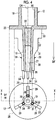
Fig. 1 is an exploded perspective view of a blood test kit. -
Fig. 2 is a perspective view showing a state where a syringe, an adapter for blood dispensing, and a centrifugal container are integrated. -
Fig. 3 is a perspective view of the adapter for blood dispensing. -
Fig. 4 shows a longitudinal sectional view (cut section of X-X) and a plan view of the adapter for blood dispensing. -
Fig. 5 is a perspective view of a medicine-holding body. -
Fig. 6 is a table showing characteristics of candidate materials of fibers forming the medicine-holding body. -
Fig. 7 is a graph showing a relationship between the anticoagulant concentration and the medicine-holding body surface area in a case of a dispensing speed of 500 µL/second. -
Fig. 8 is a graph showing a relationship between the occurrence rate of hemolysis and the medicine-holding body surface area. -
Fig. 9 is a graph showing a relationship between the void volume and the medicine-holding body surface area. -
Fig. 10 is a graph showing a relationship between the injection resistance and the medicine-holding body surface area. -
Fig. 11 is a table showing the occurrence rate of hemolysis and the anticoagulant concentration in Comparative Examples and Example. - A
blood test kit 10 inFigs. 1 and2 is used for testing blood collected from a living body. Theblood test kit 10 is configured of asyringe 11 corresponding to an injector, an adapter for blood dispensing 12, and acentrifugal container 13 corresponding to a sample container. - The
syringe 11 has acylindrical cylinder 14 and aplunger 15. A small-diameterdistal portion 16 is provided in thecylinder 14. Anopening 17 through which blood is drawn into thecylinder 14 and blood within thecylinder 14 is discharged is formed in thedistal portion 16. Theplunger 15 has a diameter substantially the same as the inner diameter of thecylinder 14 and is inserted into thecylinder 14 from a proximal end (not shown in the drawing) on a side opposite to thedistal portion 16. - The adapter for blood dispensing 12 is made of a transparent resin, for example, polyethylene, polypropylene, and polystyrene and is formed into a tubular shape. The adapter for blood dispensing 12 has a
fitting portion 18 and anozzle portion 19. Thefitting portion 18 has afitting hole 20 having an inner diameter substantially the same as the outer diameter of thedistal portion 16 of thesyringe 11. The adapter for blood dispensing 12 is provided to a user in a state where thenozzle portion 19 is inserted into aninjection port 21 of thecentrifugal container 13. In a case of dispensing blood into thecentrifugal container 13 from thesyringe 11, thefitting hole 20 is fitted with thedistal portion 16 of thesyringe 11, and the adapter for blood dispensing enters a state shown inFig. 2 . - The
centrifugal container 13 has a capacity of, for example, 600 µL to 1 mL. Thecentrifugal container 13 is a container for separating blood into, for example, a plasma component (or serum component) and a blood cell component consisting of red blood cells or white blood cells. Thecentrifugal container 13 is rotated by being put on a centrifugal separator (not shown in the drawing) after blood is dispensed. Since the plasma component (or serum component) and the blood cell component have different specific gravities, the plasma component (or serum component) and the blood cell component are centrifuged by the action of centrifugal force caused by this rotation. - The
blood test kit 10 is a so-called disposal type blood test kit which is discarded after a single use and is used for each blood sample of a living body. The adapter for blood dispensing 12 and thecentrifugal container 13 excluding thesyringe 11 may be set as a disposal type. - An alternate long and short dash line shown by a reference numeral CA is a central axis of the
syringe 11, the adapter for blood dispensing 12, and thecentrifugal container 13. Thesyringe 11, the adapter for blood dispensing 12, and thecentrifugal container 13 are integrated in a state where these central axes CA thereof are coincident with each other. An arrow shown by a reference numeral DF is a direction which is parallel to that of the central axis CA and is a flowing direction, that is, a direction in which blood flows from thesyringe 11 to thecentrifugal container 13 through the adapter for blood dispensing 12. - In
Figs. 3 and4 in which the adapter for blood dispensing 12 is shown in detail, aflange 25 is formed between thefitting portion 18 and thenozzle portion 19. Theflange 25 is a disk protruding in a direction perpendicular to the central axis CA which is set as a center. Theflange 25 functions as a gripping portion of the adapter for blood dispensing 12. Anotch 26 for preventing rolling is provided in theflange 25. - The
nozzle portion 19 has a substantially cylindrical shape in which theflow path 27 for blood is formed around the central axis CA. Theflow path 27 communicates with thefitting hole 20 at an end on an upstream side (hereinafter, upstream end) in the flowing direction DF. In addition, adischarge port 28 of blood is formed at an end on a downstream side (hereinafter, downstream end) in the flowing direction DF of theflow path 27. That is, thefitting hole 20 and thedischarge port 28 communicate with each other via theflow path 27. Blood from thesyringe 11 is received by thefitting hole 20 and flows toward thedischarge port 28 through theflow path 27. - The
flow path 27 has a tapered shape of which the diameter is smaller than that of thefitting hole 20 at the upstream end and is gradually reduced toward the downstream end. Thenozzle portion 19 also has the tapered shape of which the diameter is gradually reduced toward the downstream side from the upstream end, in accordance with the tapered shape of thisflow path 27. - For example, the length of the adapter for blood dispensing 12 along the flowing direction DF is about 20 mm, the diameter of the
fitting portion 18 is about 6 mm, the diameter of theflange 25 is about 12 mm, the diameter of theflow path 27 at the upstream end is about 2.2 mm, and the diameter of the downstream end is about 1.2 mm. - Three
ribs 29 are formed on an outer peripheral surface of thenozzle portion 19 at equal intervals (every 120°). Theribs 29 are elongated thin plates which protrude in a direction orthogonal to the central axis CA and extend along the flowing direction DF. Theribs 29 are formed substantially over the entire length of thenozzle portion 19 from theflange 25 to the position in front of thedischarge port 28. - Each
rib 29 has asmall piece portion 30, a taperedportion 31, afitting portion 32, and astopper portion 33 in order from the downstream end. Thesmall piece portion 30 has a length from the position in front of thedischarge port 28 to substantially a center of thenozzle portion 19. The protruding amount of thesmall piece portion 30 in a direction orthogonal to the central axis CA is smaller than the inner diameter of theinjection port 21 of thecentrifugal container 13. The taperedportion 31 is an inclined surface portion which connects thesmall piece portion 30 to thefitting portion 32. The protruding amount of the tapered portion increases from thesmall piece portion 30 toward thefitting portion 32. - The protruding amount of the
fitting portion 32 is the same as or slightly larger than the inner diameter of theinjection port 21. Thestopper portion 33 protrudes from an edge of thefitting portion 32 at a right angle and the protruding amount thereof is larger than the inner diameter of theinjection port 21. - In a case of inserting the
nozzle portion 19 into theinjection port 21, thesmall piece portion 30 of which the protruding amount is smaller than the inner diameter of theinjection port 21 first passes through theinjection port 21, and then, the taperedportion 31 passes through theinjection port 21. At this time, the taperedportion 31 functions as a guide for allowing thefitting portion 32 to smoothly reach an edge of theinjection port 21. - The
fitting portion 32 has a protruding amount the same as or slightly larger than the inner diameter of theinjection port 21. Therefore, the fitting portion comes into contact with the inner peripheral surface of theinjection port 21 and is fitted with theinjection port 21. Furthermore, in a case where thenozzle portion 19 is inserted into the injection port, thestopper portion 33 of which the protruding amount is larger than the inner diameter of theinjection port 21 abuts on the edge of theinjection port 21. Accordingly, insertion of thenozzle portion 19 into theinjection port 21 is restricted. - As described above, the
ribs 29 are disposed at intervals. For this reason, a ventilation path is secured between the outer peripheral surface of thenozzle portion 19 and the inner peripheral surface of theinjection port 21 in a state where thenozzle portion 19 is inserted into theinjection port 21. Gas-liquid exchange in a case of dispensing blood into thecentrifugal container 13 is securely performed due to this ventilation path, and therefore, the dispensing is smoothly performed. - Three
projection portions 34 are provided at downstream ends of theribs 29 at equal intervals (every 120°) similarly to theribs 29. Theprojection portions 34 are cylinders which are projected toward a downstream side in the flowing direction DF from the periphery of thedischarge port 28. Theprojection portions 34 prevent remaining blood being pushed out from thedischarge port 28 due to an effect of surface tension from adhering to theinjection port 21 and the vicinity thereof, in a case of removing thenozzle portion 19 from theinjection port 21 after the dispensing of blood. - The medicine-holding
body 35 is disposed in theflow path 27. The medicine-holdingbody 35 is disposed from a portion of theflow path 27 of which the diameter is smaller than that of thefitting hole 20 at the upstream end to the position in front of the taperedportion 31 of eachrib 29. - In
Fig. 5 , the medicine-holdingbody 35 is formed to have a cylindrical shape by bundling a plurality ofelongated fibers 40 having a circular cross section. Thefibers 40 are bundled by aligning a longitudinal direction thereof in the flowing direction DF. Thefibers 40 have, for example, a diameter of 30 µm, a length of 5 mm, and a surface area of about 0.47 mm2. The medicine-holdingbody 35 has, for example, a diameter of 2.2 mm. - The anticoagulant is adsorbed and held on the surface of each of the
fibers 40 as a medicine as shown by hatching and areference numeral 41. The anticoagulant 41 suppresses coagulation of blood. Examples of the anticoagulant 41 include ethylenediaminetetraacetic acid (EDTA), heparin sodium, heparin lithium, sodium citrate, trisodium citrate, fluoride, and potassium oxalate. -
Fig. 6 is Table 45 showing characteristics of polypropylene, polyethylene, polyester, and glass which are candidate materials of thefibers 40. Among these materials, polypropylene has the largest contact angle. Then, the contact angle becomes smaller in order of polyethylene and polyester, and glass has the smallest contact angle. The larger the contact angle is, the higher the water repellency is. The smaller the contact angle is, the higher the hydrophilicity is. Therefore, among these, polypropylene has the highest water repellency. Then, the water repellency becomes lower in order of polyethylene and polyester. Glass has the highest hydrophilicity. - The contact angle refers to an angle formed between the surface of a liquid and the surface of a solid (in this case, a candidate material of the fibers 40) at a boundary line at which these three phases come into contact with each other, in a case where the surface of the solid comes into contact with a liquid (water) and gas (air). A liquid is added dropwise onto the surface of the solid parallel to the horizontal surface to be entered into a stationary state. Then, the state is photographed from a direction parallel to the horizontal surface to acquire an image. The acquired image is analyzed and the contact angle is measured using a contact angle meter which obtains the contact angle.
- A material having comparatively high hydrophilicity, in specific, a material having a contact angle smaller than 80° is desired as the material for the
fibers 40 constituting the medicine-holdingbody 35 in order to make adsorption of blood components hardly occur. From such viewpoint, glass is the most suitable material for thefibers 40 among the materials in Table 45. However, as described in remarks, calcium, chlorine, sodium and the like contained in glass are eluted into blood. For this reason, it is impossible to accurately measure the blood components. Accordingly, in the present invention, polyester which is a material, of which the hydrophilicity is next highest to glass and the contact angle is smaller than 80°, and is a resin in which there is no elution of contained components into blood, is employed as the material of thefibers 40. - In the material having a contact angle larger than or equal to 80° (in Table 45, polypropylene and polyethylene), a proportion of adsorbing blood components, in particular, proteins and red blood cells particularly increases. If the adsorption of blood components occurs, it is impossible to accurately measure the blood components. In a case where red blood cells are adsorbed, if the speed (hereinafter, referred to as dispensing speed) for dispensing blood into the
centrifugal container 13 from thesyringe 11 is comparatively high, hemolysis occurs. For this reason, it is preferable that the contact angle of the material of thefibers 40 is smaller than 80°. In addition, the material, such as glass in Table 45 or metal of which contained components are eluted into blood is not suitable as the material for thefibers 40. A resin of which contained components are not eluted into blood is preferable. - Here, the
fibers 40 are made of polyester, but are not particularly limited as long as the material is a resin and the contact angle of the material is smaller than 80°. Examples thereof may include polyvinylidene chloride (75°), polyacrylonitrile (49°), NEOPRENE (registered trademark, 73°), nylon 6 (52°), N-methoxymethyl polyamide (62°), polymethyl acrylate (52°), polymethyl methacrylate (62°), polyvinyl chloride (68°), polyvinyl acetate (57°), VINYLON (registered trademark, 61°), cellulose diacetate (53°), cellulose triacetate (67°), a phenol resin (63°), and chlorinated rubber (68°). - The medicine-holding
body 35 is constituted such that, in a case where a volume of 600 µL to 1 mL of blood with a hematocrit value of 30% to 55% is dispensed into thecentrifugal container 13 from thesyringe 11 over 1 second or longer, the concentration of the anticoagulant 41 in blood within the centrifugal container 13 (hereinafter, referred to as anticoagulant concentration) becomes 10 U/mL to 40 U/mL which is within a target range. - Specifically, 20 U of the anticoagulant 41 is held in the medicine-holding
body 35. In this case, in a case where 500 µL of blood is dispensed into thecentrifugal container 13 from thesyringe 11, if all the anticoagulant 41 is dissolved in blood, the anticoagulant concentration becomes 40 U/mL which is an upper limit value of the target range. The actual amount of blood dispensed into thecentrifugal container 13 is 600 µL to 1 mL which is the capacity of thecentrifugal container 13. For this reason, if 20 U of the anticoagulant 41 is held in the medicine-holdingbody 35, the anticoagulant concentration in a case where all the anticoagulant 41 is dissolved in blood in a case where, for example, 600 µL of blood is dispensed becomes 20 U / 600 µL ≅ 33 U/mL, and therefore, does not exceed the upper limit value of 40 U/mL. -
Fig. 7 is a graph showing a relationship between the anticoagulant concentration and the surface area of the medicine-holding body 35 (hereinafter, referred to as medicine-holding body surface area) in a case of a dispensing speed of 500 µL/second. The dispensing speed of 500 µL/second is the highest dispensing speed that can be considered. If the dispensing speed is high, the amount of the anticoagulant 41 dissolved in blood is naturally decreased. For this reason, thedispensing speed 500 µL/second is the most severe condition for maintaining the anticoagulant concentration to be greater than or equal to 10 U/mL which is a lower limit value. In addition, the medicine-holding body surface area is a total surface area of a plurality offibers 40 constituting the medicine-holdingbody 35 and is, specifically, a value obtained by multiplying the surface area of thefibers 40 by the number offibers 40. - An approximate line L1 of three plots having a medicine-holding body surface area less than or equal to 300 mm2 (excluding plots in the vicinity of a medicine-holding body surface area of 500 mm2) is focused. The medicine-holding body surface area at a point P1 at which the approximate line L1 intersects with a line of the lower limit value of the anticoagulant concentration of 10 U/mL is 10 mm2 as shown in a broken line frame F1. This shows that the anticoagulant concentration becomes greater than or equal to the lower limit value of 10 U/mL even under the most severe condition such as a dispensing speed of 500 µL/second if the medicine-holding
body 35 has a surface area greater than or equal to 10 mm2. Accordingly, the medicine-holdingbody 35 has a surface area greater than or equal to 10 mm2 in order to make the anticoagulant concentration be greater than or equal to the lower limit value of 10 U/mL. - In a case where the anticoagulant concentration is less than the lower limit value of 10 U/mL, blood within the
centrifugal container 13 coagulates. In contrast, in a case where the anticoagulant concentration exceeds the upper limit value of 40 U/mL, it exceeds an allowable amount of a film slide used for measuring blood components. In either case, it is impossible to accurately measure blood components. - The medicine-holding
body 35 is formed such that the occurrence rate of hemolysis becomes less than or equal to 10%. Here, the occurrence rate refers to the probability that the effect Δ (= measurement result - measurement result in a case where there is no hemolysis) on Lactate Dehydrogenase (LDH) and Creatine PhosphoKinase (CPK) which are measurement items that are increased due to the occurrence of hemolysis, the effect being caused by hemolysis exceeds a prescribed range of ± 20 U/L. The condition such as an occurrence rate of hemolysis being less than or equal to 10% is satisfied in a case where both of the occurrence rate of LDH and the occurrence rate of CPK are less than or equal to 10% and is a condition which the adapter for blood dispensing 12, as a product, need to at least satisfy. -
Fig. 8 is a graph showing a relationship between the occurrence rate of hemolysis and the medicine-holding body surface area. A legend of a white blank rectangle and a legend of a white blank triangle respectively represent LDH and CPK. An approximate line L2 of a plot of LDH and an approximate line L3 of a plot of CPK are focused. First, the medicine-holding body surface area at a point P3 at which the approximate line L3 intersects with a line of the occurrence rate of 10% is about 750 mm2. For this reason, if the medicine-holding body surface area is set to be about less than 750 mm2, it is possible to at least suppress the occurrence rate of CPK to be less than or equal to 10%. However, in the case where the medicine-holding body surface area is about 750 mm2, the occurrence rate of LDH exceeds 10%, and therefore, it is impossible to maintain the occurrence rate of hemolysis to be less than or equal to 10%. - In contrast, the medicine-holding body surface area at a point P2 at which the approximate line L2 intersects with the line of the occurrence rate of 10% is 600 mm2 as shown by a broken line frame F2. In the case where the medicine-holding body surface area is 600 mm2, both of the occurrence rate of LDH and the occurrence rate of CPK are less than or equal to 10%. For this reason, in the case where the medicine-holding body surface area is 600 mm2, it can be seen that the occurrence rate of hemolysis is less than or equal to 10%. Accordingly, the medicine-holding
body 35 has a surface area less than 600 mm2 in order to maintain the occurrence rate of hemolysis to be less than or equal to 10%. - To summarize the description using
Figs. 7 and8 , the surface area of the medicine-holdingbody 35 is greater than or equal to 10 mm2 and less than 600 mm2. If the medicine-holding body surface area is greater than or equal to 10 mm2, it is possible to maintain the anticoagulant concentration to be greater than or equal to 10 U/mL which is a lower limit value. In addition, if the medicine-holding body surface area is less than 600 mm2, it is possible to maintain the occurrence rate of hemolysis to be less than or equal to 10%. -
Fig. 9 is a graph showing a relationship between the void volume and the medicine-holding body surface area. Here, the void volume refers to a proportion (unit: %) of voids formed between the plurality offibers 40 occupying the volume of the medicine-holding body 35 (radius of the medicine-holdingbody 35 × radius × π × length) in a state where the medicine-holdingbody 35 is disposed in theflow path 27. The void volume at a point P4 at which an approximate line L4 with each plot intersects with a line of the medicine-holding body surface area of 600 mm2 is 65% as shown by a broken line frame F4. That is, the medicine-holding body surface area of 600 mm2 corresponds to a void volume of 65%. For this reason, the condition of maintaining the occurrence rate of hemolysis to be less than or equal to 10% which corresponds to the medicine-holding body surface area being less than 600 mm2 which has been described usingFig. 8 can also be called a void volume being greater than 65%. The void volume in a case where the medicine-holding body surface area is 10 mm2 is about 99.4%. - The volume of the medicine-holding
body 35 is slightly compressed by disposing the medicine-holdingbody 35 in theflow path 27. For this reason, in order to make the void volume in a state where the medicine-holdingbody 35 is disposed in theflow path 27 be greater than 65%, it is necessary to make the void volume before the medicine-holding body is disposed in theflow path 27 be greater than 65% in a case of considering the fact that the volume of the medicine-holding body is slightly compressed. For example, in a case where the compression ratio of the volume of the medicine-holdingbody 35 due to the disposition of the medicine-holding body in theflow path 27 is 78%, if the void volume before the medicine-holding body is disposed in theflow path 27 is greater than 85%, 85 multiplied by 0.78 is 66.3. Therefore, the void volume in a state where the medicine-holdingbody 35 is disposed in theflow path 27 becomes greater than or equal to 65%. -
Fig. 10 is a graph showing a relationship between the injection resistance and the medicine-holding body surface area. Here, the injection resistance refers to a force (unit: N) required in a case of allowing blood to flow into the adapter for blood dispensing 12. The injection resistance at a point P5 at which an approximate line L5 of each plot intersects with a line of the medicine-holding body surface area of 600 mm2 is 8 N as shown by a broken line frame F5. That is, the medicine-holding body surface area of 600 mm2 corresponds to an injection resistance of 8 N. For this reason, the condition of maintaining the occurrence rate of hemolysis to be less than or equal to 10% which corresponds to the medicine-holding body surface area being less than 600 mm2 which has been described usingFig. 8 can also be expressed as an injection resistance being less than 8 N. The injection resistance in a case of the medicine-holding body surface area being 10 mm2 is about 1.5 N. - The medicine-holding
body 35 may be commercially available on the market. For example, it is possible to use a polyester fiber rod manufactured by ASAHI FIBER INDUSTRY CO., LTD. - Next, an operation of the above-described configuration will be described. In a case of performing a blood test using the
blood test kit 10, the adapter for blood dispensing 12 which is integrated with thecentrifugal container 13 by inserting thenozzle portion 19 into theinjection port 21 of thecentrifugal container 13 is first prepared. Then, the adapter for blood dispensing 12 is attached to thesyringe 11 by fitting thedistal portion 16 of thesyringe 11 in which blood is stored in thecylinder 14 with thefitting hole 20 of the adapter for blood dispensing 12 to make a state shown inFig. 2 . - Thereafter, the
plunger 15 is pushed in the flowing direction DF. Accordingly, pressure is applied to the blood within thecylinder 14 and the blood is discharged from theopening 17. Blood discharged from theopening 17 is received by thefitting hole 20 of the adapter for blood dispensing 12 and passes through the medicine-holdingbody 35 disposed in theflow path 27. Accordingly, the anticoagulant 41 held in the medicine-holdingbody 35 is mixed into the blood. - The medicine-holding
body 35 is formed of the plurality offibers 40 bundled by aligning a longitudinal direction thereof in the flowing direction DF as shown inFig. 5 . In the case where thefibers 40 are bundled by aligning the longitudinal direction in the flowing direction DF, the area where blood collides with thefibers 40 during dispensing is remarkably reduced compared to a case where the fibers are bundled by aligning the longitudinal direction in a direction orthogonal to the flowing direction DF. As a result, it is possible to reduce the number of times that red blood cells collide with thefibers 40. Accordingly, hemolysis hardly occurs compared to the sheet which is formed of cotton or a non-woven fabric capable of adsorbing a medicine and is disclosed inJP2015-187592A - The
fibers 40 are made of polyester which is a material of which the contact angle is smaller than 80° as shown inFig. 6 . For this reason, the fibers have high hydrophilicity compared to the sheet which is formed of cotton or a non-woven fabric capable of adsorbing a medicine and is disclosed inJP2015-187592A - Furthermore, the surface area of the medicine-holding
body 35 is greater than or equal to 10 mm2 and less than 600 mm2 as shown inFigs. 7 and8 . For this reason, it is possible to maintain the anticoagulant concentration to be greater than or equal to 10 U/mL which is a lower limit value and to maintain the occurrence rate of hemolysis to be less than or equal to 10 %. Accordingly, it is possible to maintain the accuracy of measurement of blood components at a higher level. - A condition such as a medicine-holding body surface area being greater than or equal to 10 mm2 is derived at the most severe dispensing speed of 500 µL/second. For this reason, even if the dispensing speed of blood is slightly changed by a user, it is possible to always maintain the anticoagulant concentration to be greater than or equal to 10 U/mL which is a lower limit value.
- Blood mixed with the anticoagulant 41 is discharged from the
discharge port 28 at the downstream end of theflow path 27 into thecentrifugal container 13. After the blood is injected into thecentrifugal container 13 in a predetermined amount, the adapter for blood dispensing 12 for eachsyringe 11 is removed from thecentrifugal container 13. - After the removal of the adapter for blood dispensing 12, the
centrifugal container 13 is put on a centrifugal separator, and the blood is centrifuged into plasma components (or serum components) and blood cell components. Then, the centrifuged components are collected on a film slide which is then put into a component analysis machine. The blood test is finally completed. - Table 50 in
Fig. 11 shows the occurrence rate of hemolysis and the anticoagulant concentration (the lowest number of dispensing being 5 times) in a case where a volume of 600 µL of whole blood of a dog with a hematocrit value of 53% is dispensed 5 times over 3 seconds for each time (dispensing speed of 200 µL/second). Comparative Example 1 shows a case where the wall surface of theflow path 27 is coated with the anticoagulant 41 without using a medicine-holding body and Comparative Example 2 shows a case where the sheet formed of cotton or a non-woven fabric inJP2015-187592A fibers 40 bundled by arranging a longitudinal direction in the flowing direction DF is used. In all cases, heparin lithium is used as the anticoagulant 41. A solution obtained by dissolving 20 U of heparin lithium in a 1.0 wt% aqueous solution of polyvinyl alcohol was used for performing coating on the wall surface (Comparative Example 1) or for being immersed in the medicine-holding bodies (Comparative Example 2 and Example) and was dried. - In the case of Comparative Example 1, the length of the wall surface of the
flow path 27 coated with the anticoagulant 41 in the flowing direction DF is 4.5 mm. In the case of Comparative Example 2, the sheet formed of cotton or a non-woven fabric has a length of 4.5 mm, a thickness of 0.43 mm, a density of 75 g/m2, a fiber diameter of about 50 µm, and a medicine-holding body surface area of about 220 mm2. More specifically, the sheet in Comparative Example 2 is obtained such that a product having a product name of GLASS FIBER DIAGNOSTIC PAD and a product model number of GFDX 203000 manufactured by Merck Millipore Corporation is suitably unraveled by cutting the product in a length of 4.5 mm. In the case of Example, thefibers 40 have a diameter of 30 µm, a length of 4.5 mm, and a medicine-holding body surface area of about 249 mm2, and the number of fibers is 586. - According to Table 50, in Comparative Example 2, one dispensing out of the 5 times could not be performed and the effect Δ caused by hemolysis exceeded the prescribed range in 3 times of dispensing including the one time of dispensing which could not be performed. Therefore the occurrence rate is 60% which is high. In contrast, hemolysis did not occur in 5 times of dispensing in either of Comparative Example 1 and Example. In addition, in Comparative Example 1, the anticoagulant concentration is 2 U/mL which is much less than 10 U/mL of the lower limit value. In contrast, the anticoagulant concentration in Comparative Example 2 is 32 U/mL and the anticoagulant concentration in Example is 28 U/mL, which are within the target range of 10 U/mL to 40 U/mL. Accordingly, in Comparative Example 1, the anticoagulant concentration is not within the target range even though there is no occurrence of hemolysis. In addition, in Comparative Example 2, hemolysis occurs even though the anticoagulant concentration is within the target range. In contrast, in Example, it was confirmed that there was no occurrence of hemolysis and the anticoagulant concentration was within the target range.
- A resin such as polyester has been exemplified as the material of the
fibers 40. However, other materials except for resin may be used as long as there is no elution of the contained components into blood and the contact angle is smaller than 80°. - A coagulation accelerant for promoting coagulation of blood or a separating agent (a serum separating agent or a plasma separating agent) may be used as a medicine instead of the anticoagulant 41. Examples of the coagulation accelerant include silica, thrombin, and diatomaceous earth. An example of the separating agent includes polyester gel.
- The injector is not limited to the
syringe 11 and may be a pipette. In addition, the sample container is not limited to thecentrifugal container 13. Blood may be allowed to stand after being dispensed. Furthermore, the wall surface of theflow path 27 may be coated with a medicine as well as the medicine-holdingbody 35. - The present invention is not limited to the above-described embodiment, and as a matter of course, various configurations can be adopted without departing from the gist of the present invention.
-
- 10: blood test kit
- 11: syringe
- 12: adapter for blood dispensing
- 13: centrifugal container
- 14: cylinder
- 15: plunger
- 16: distal portion
- 17: opening
- 18: fitting portion
- 19: nozzle portion
- 20: fitting hole
- 21: injection port
- 25: flange
- 26: notch
- 27: flow path
- 28: discharge port
- 29: rib
- 30: small piece portion
- 31: tapered portion
- 32: fitting portion
- 33: stopper portion
- 34: projection portion
- 35: medicine-holding body
- 40: fiber
- 41: anticoagulant
- 45, 50: table
- CA: central axis
- DF: flowing direction
- L1 to L5: approximate line
- P1 to P5: point
- F1, F2, F4, F5: frame
Claims (5)
- An adapter for blood dispensing comprising:a fitting portion which is fitted with a distal portion of an injector and receives blood from the injector;a nozzle portion in which a flow path, through which the blood flows toward a sample container, is provided and which is inserted into the sample container; anda medicine-holding body which is disposed in the flow path, holds a medicine to be mixed into the blood, and is formed of a plurality of fibers bundled by aligning a longitudinal direction thereof in a flowing direction which is a direction in which the blood flows.
- The adapter for blood dispensing according to claim 1,wherein the fibers are resins and are made of a material of which a contact angle is smaller than 80°.
- The adapter for blood dispensing according to claim 2,wherein the fibers are made of polyester.
- The adapter for blood dispensing according to any one of claims 1 to 3,wherein a surface area of the medicine-holding body is greater than or equal to 10 mm2 and less than 600 mm2.
- The adapter for blood dispensing according to any one of claims 1 to 4,wherein the medicine is an anticoagulant for suppressing coagulation of the blood.
Applications Claiming Priority (1)
| Application Number | Priority Date | Filing Date | Title |
|---|---|---|---|
| JP2016167572A JP6622158B2 (en) | 2016-08-30 | 2016-08-30 | Blood dispensing adapter |
Publications (2)
| Publication Number | Publication Date |
|---|---|
| EP3290118A1 true EP3290118A1 (en) | 2018-03-07 |
| EP3290118B1 EP3290118B1 (en) | 2019-04-17 |
Family
ID=59745714
Family Applications (1)
| Application Number | Title | Priority Date | Filing Date |
|---|---|---|---|
| EP17187315.1A Active EP3290118B1 (en) | 2016-08-30 | 2017-08-22 | Adapter for blood dispensing |
Country Status (3)
| Country | Link |
|---|---|
| US (1) | US10842928B2 (en) |
| EP (1) | EP3290118B1 (en) |
| JP (1) | JP6622158B2 (en) |
Citations (3)
| Publication number | Priority date | Publication date | Assignee | Title |
|---|---|---|---|---|
| US5782759A (en) * | 1996-12-30 | 1998-07-21 | Warner-Lambert Company | Cardiovascular testing device |
| US20110092686A1 (en) * | 2008-03-28 | 2011-04-21 | Pelican Group Holdings, Inc. | Multicapillary sample preparation devices and methods for processing analytes |
| JP2015187592A (en) | 2013-07-02 | 2015-10-29 | 富士フイルム株式会社 | Adapter for blood sample dispensing, and dispensing kit and needle kit provided therewith |
Family Cites Families (11)
| Publication number | Priority date | Publication date | Assignee | Title |
|---|---|---|---|---|
| US5538735A (en) * | 1993-02-19 | 1996-07-23 | Ahn; Sam S. | Method of making a drug delivery system using hollow fibers |
| US7967769B2 (en) * | 2003-04-08 | 2011-06-28 | Rox Medical Inc. | Implantable arterio-venous shunt devices and methods for their use |
| JP2009532099A (en) * | 2006-03-31 | 2009-09-10 | ザ プロクター アンド ギャンブル カンパニー | Absorbent article comprising a fibrous structure comprising synthetic fibers and a hydrophilizing agent |
| MY148625A (en) * | 2006-08-18 | 2013-05-15 | Porex Corp | Sintered polymeric materials and applications thereof |
| EP1930034B1 (en) * | 2006-12-07 | 2012-11-14 | Thoratec LLC | An integrated centrifugal blood pump-oxygenator, an extracorporeal life support system and a method of de-bubbling and priming an extracorporeal life support system |
| AU2009228086B2 (en) | 2008-03-28 | 2015-04-23 | Biotix Inc. | Sample preparation devices and methods for processing analytes |
| JP2011133235A (en) * | 2009-12-22 | 2011-07-07 | Physical Screening Inc | Storage device for liquid to be tested |
| WO2012142180A1 (en) * | 2011-04-12 | 2012-10-18 | Tianxin Wang | Methods to detect and treat diseases |
| AU2013295198B2 (en) * | 2012-07-25 | 2017-02-02 | Solventum Intellectual Properties Company | Mobile system for separating donor blood by means of gravitational force |
| CN104487105B (en) * | 2012-07-25 | 2016-12-07 | 旭化成医疗株式会社 | Blood processing filter, blood circuit and blood processing |
| EP3271472A1 (en) * | 2015-03-19 | 2018-01-24 | 3M Innovative Properties Company | Devices, methods, kits, and systems for detecting microorganism strains or target cellular analytes in a fluid sample |
-
2016
- 2016-08-30 JP JP2016167572A patent/JP6622158B2/en active Active
-
2017
- 2017-08-22 EP EP17187315.1A patent/EP3290118B1/en active Active
- 2017-08-25 US US15/686,178 patent/US10842928B2/en active Active
Patent Citations (4)
| Publication number | Priority date | Publication date | Assignee | Title |
|---|---|---|---|---|
| US5782759A (en) * | 1996-12-30 | 1998-07-21 | Warner-Lambert Company | Cardiovascular testing device |
| US20110092686A1 (en) * | 2008-03-28 | 2011-04-21 | Pelican Group Holdings, Inc. | Multicapillary sample preparation devices and methods for processing analytes |
| JP2015187592A (en) | 2013-07-02 | 2015-10-29 | 富士フイルム株式会社 | Adapter for blood sample dispensing, and dispensing kit and needle kit provided therewith |
| US20160100786A1 (en) * | 2013-07-02 | 2016-04-14 | Fujifilm Corporation | Adapter for blood sample dispensing, and dispensing kit and needle kit provided therewith |
Also Published As
| Publication number | Publication date |
|---|---|
| JP6622158B2 (en) | 2019-12-18 |
| US20180055990A1 (en) | 2018-03-01 |
| US10842928B2 (en) | 2020-11-24 |
| EP3290118B1 (en) | 2019-04-17 |
| JP2018036085A (en) | 2018-03-08 |
Similar Documents
| Publication | Publication Date | Title |
|---|---|---|
| JP2019095453A (en) | Sample collection and method and appliance for sample separation | |
| EP1580551B1 (en) | Plasma or serum separation membrane and filter apparatus including the plasma or serum separation membrane | |
| US10126211B2 (en) | Bodily fluid sampler | |
| CN102573629B (en) | A blood sampling device | |
| RU2752706C1 (en) | Bodily fluid collection apparatus and collection module | |
| JP2020095057A (en) | Methods and devices for sample collection and sample separation | |
| US20210380928A1 (en) | Cell separation filter, filtering device, and manufacturing method for cell separation filter | |
| EP3154666B1 (en) | Capillary pressure re-set mechanism and applications | |
| WO2006098297A1 (en) | Sampling liquid container | |
| US20160100786A1 (en) | Adapter for blood sample dispensing, and dispensing kit and needle kit provided therewith | |
| KR20150016958A (en) | Sample introduction system | |
| JP2004344874A (en) | Separation membrane of plasma or serum and filter apparatus using separation membrane of plasma or serum | |
| EP3290118B1 (en) | Adapter for blood dispensing | |
| DE69829531T2 (en) | Removal vasculature | |
| US10639625B2 (en) | Pipette tip and liquid injection method | |
| AU2021371448A1 (en) | Sample collection apparatus | |
| JP4078460B2 (en) | Plasma separation filter, plasma separation method and plasma separation apparatus using the same | |
| JP2004325412A (en) | Blood examining container | |
| JP5909470B2 (en) | Body fluid collector | |
| WO2022064475A1 (en) | Liquid sample processing device | |
| JP6493883B2 (en) | Film forming method and adapter manufacturing method | |
| CN116165391A (en) | Sample processing method and sample analyzer | |
| JP2016118572A (en) | Body liquid collection tool | |
| JPH02305554A (en) | Liquid sample trace amount sampling tube |
Legal Events
| Date | Code | Title | Description |
|---|---|---|---|
| PUAI | Public reference made under article 153(3) epc to a published international application that has entered the european phase |
Free format text: ORIGINAL CODE: 0009012 |
|
| STAA | Information on the status of an ep patent application or granted ep patent |
Free format text: STATUS: THE APPLICATION HAS BEEN PUBLISHED |
|
| AK | Designated contracting states |
Kind code of ref document: A1 Designated state(s): AL AT BE BG CH CY CZ DE DK EE ES FI FR GB GR HR HU IE IS IT LI LT LU LV MC MK MT NL NO PL PT RO RS SE SI SK SM TR |
|
| AX | Request for extension of the european patent |
Extension state: BA ME |
|
| STAA | Information on the status of an ep patent application or granted ep patent |
Free format text: STATUS: REQUEST FOR EXAMINATION WAS MADE |
|
| 17P | Request for examination filed |
Effective date: 20180320 |
|
| RBV | Designated contracting states (corrected) |
Designated state(s): AL AT BE BG CH CY CZ DE DK EE ES FI FR GB GR HR HU IE IS IT LI LT LU LV MC MK MT NL NO PL PT RO RS SE SI SK SM TR |
|
| STAA | Information on the status of an ep patent application or granted ep patent |
Free format text: STATUS: EXAMINATION IS IN PROGRESS |
|
| 17Q | First examination report despatched |
Effective date: 20180530 |
|
| GRAP | Despatch of communication of intention to grant a patent |
Free format text: ORIGINAL CODE: EPIDOSNIGR1 |
|
| STAA | Information on the status of an ep patent application or granted ep patent |
Free format text: STATUS: GRANT OF PATENT IS INTENDED |
|
| INTG | Intention to grant announced |
Effective date: 20181113 |
|
| GRAS | Grant fee paid |
Free format text: ORIGINAL CODE: EPIDOSNIGR3 |
|
| GRAA | (expected) grant |
Free format text: ORIGINAL CODE: 0009210 |
|
| STAA | Information on the status of an ep patent application or granted ep patent |
Free format text: STATUS: THE PATENT HAS BEEN GRANTED |
|
| AK | Designated contracting states |
Kind code of ref document: B1 Designated state(s): AL AT BE BG CH CY CZ DE DK EE ES FI FR GB GR HR HU IE IS IT LI LT LU LV MC MK MT NL NO PL PT RO RS SE SI SK SM TR |
|
| REG | Reference to a national code |
Ref country code: GB Ref legal event code: FG4D |
|
| REG | Reference to a national code |
Ref country code: CH Ref legal event code: EP |
|
| REG | Reference to a national code |
Ref country code: DE Ref legal event code: R096 Ref document number: 602017003339 Country of ref document: DE |
|
| REG | Reference to a national code |
Ref country code: AT Ref legal event code: REF Ref document number: 1120964 Country of ref document: AT Kind code of ref document: T Effective date: 20190515 Ref country code: IE Ref legal event code: FG4D |
|
| REG | Reference to a national code |
Ref country code: NL Ref legal event code: MP Effective date: 20190417 |
|
| REG | Reference to a national code |
Ref country code: LT Ref legal event code: MG4D |
|
| PG25 | Lapsed in a contracting state [announced via postgrant information from national office to epo] |
Ref country code: NL Free format text: LAPSE BECAUSE OF FAILURE TO SUBMIT A TRANSLATION OF THE DESCRIPTION OR TO PAY THE FEE WITHIN THE PRESCRIBED TIME-LIMIT Effective date: 20190417 |
|
| PG25 | Lapsed in a contracting state [announced via postgrant information from national office to epo] |
Ref country code: AL Free format text: LAPSE BECAUSE OF FAILURE TO SUBMIT A TRANSLATION OF THE DESCRIPTION OR TO PAY THE FEE WITHIN THE PRESCRIBED TIME-LIMIT Effective date: 20190417 Ref country code: ES Free format text: LAPSE BECAUSE OF FAILURE TO SUBMIT A TRANSLATION OF THE DESCRIPTION OR TO PAY THE FEE WITHIN THE PRESCRIBED TIME-LIMIT Effective date: 20190417 Ref country code: PT Free format text: LAPSE BECAUSE OF FAILURE TO SUBMIT A TRANSLATION OF THE DESCRIPTION OR TO PAY THE FEE WITHIN THE PRESCRIBED TIME-LIMIT Effective date: 20190817 Ref country code: SE Free format text: LAPSE BECAUSE OF FAILURE TO SUBMIT A TRANSLATION OF THE DESCRIPTION OR TO PAY THE FEE WITHIN THE PRESCRIBED TIME-LIMIT Effective date: 20190417 Ref country code: LT Free format text: LAPSE BECAUSE OF FAILURE TO SUBMIT A TRANSLATION OF THE DESCRIPTION OR TO PAY THE FEE WITHIN THE PRESCRIBED TIME-LIMIT Effective date: 20190417 Ref country code: HR Free format text: LAPSE BECAUSE OF FAILURE TO SUBMIT A TRANSLATION OF THE DESCRIPTION OR TO PAY THE FEE WITHIN THE PRESCRIBED TIME-LIMIT Effective date: 20190417 Ref country code: FI Free format text: LAPSE BECAUSE OF FAILURE TO SUBMIT A TRANSLATION OF THE DESCRIPTION OR TO PAY THE FEE WITHIN THE PRESCRIBED TIME-LIMIT Effective date: 20190417 Ref country code: NO Free format text: LAPSE BECAUSE OF FAILURE TO SUBMIT A TRANSLATION OF THE DESCRIPTION OR TO PAY THE FEE WITHIN THE PRESCRIBED TIME-LIMIT Effective date: 20190717 |
|
| PG25 | Lapsed in a contracting state [announced via postgrant information from national office to epo] |
Ref country code: RS Free format text: LAPSE BECAUSE OF FAILURE TO SUBMIT A TRANSLATION OF THE DESCRIPTION OR TO PAY THE FEE WITHIN THE PRESCRIBED TIME-LIMIT Effective date: 20190417 Ref country code: PL Free format text: LAPSE BECAUSE OF FAILURE TO SUBMIT A TRANSLATION OF THE DESCRIPTION OR TO PAY THE FEE WITHIN THE PRESCRIBED TIME-LIMIT Effective date: 20190417 Ref country code: GR Free format text: LAPSE BECAUSE OF FAILURE TO SUBMIT A TRANSLATION OF THE DESCRIPTION OR TO PAY THE FEE WITHIN THE PRESCRIBED TIME-LIMIT Effective date: 20190718 Ref country code: LV Free format text: LAPSE BECAUSE OF FAILURE TO SUBMIT A TRANSLATION OF THE DESCRIPTION OR TO PAY THE FEE WITHIN THE PRESCRIBED TIME-LIMIT Effective date: 20190417 Ref country code: BG Free format text: LAPSE BECAUSE OF FAILURE TO SUBMIT A TRANSLATION OF THE DESCRIPTION OR TO PAY THE FEE WITHIN THE PRESCRIBED TIME-LIMIT Effective date: 20190717 |
|
| REG | Reference to a national code |
Ref country code: AT Ref legal event code: MK05 Ref document number: 1120964 Country of ref document: AT Kind code of ref document: T Effective date: 20190417 |
|
| PG25 | Lapsed in a contracting state [announced via postgrant information from national office to epo] |
Ref country code: IS Free format text: LAPSE BECAUSE OF FAILURE TO SUBMIT A TRANSLATION OF THE DESCRIPTION OR TO PAY THE FEE WITHIN THE PRESCRIBED TIME-LIMIT Effective date: 20190817 |
|
| REG | Reference to a national code |
Ref country code: DE Ref legal event code: R097 Ref document number: 602017003339 Country of ref document: DE |
|
| PG25 | Lapsed in a contracting state [announced via postgrant information from national office to epo] |
Ref country code: DK Free format text: LAPSE BECAUSE OF FAILURE TO SUBMIT A TRANSLATION OF THE DESCRIPTION OR TO PAY THE FEE WITHIN THE PRESCRIBED TIME-LIMIT Effective date: 20190417 Ref country code: SK Free format text: LAPSE BECAUSE OF FAILURE TO SUBMIT A TRANSLATION OF THE DESCRIPTION OR TO PAY THE FEE WITHIN THE PRESCRIBED TIME-LIMIT Effective date: 20190417 Ref country code: AT Free format text: LAPSE BECAUSE OF FAILURE TO SUBMIT A TRANSLATION OF THE DESCRIPTION OR TO PAY THE FEE WITHIN THE PRESCRIBED TIME-LIMIT Effective date: 20190417 Ref country code: EE Free format text: LAPSE BECAUSE OF FAILURE TO SUBMIT A TRANSLATION OF THE DESCRIPTION OR TO PAY THE FEE WITHIN THE PRESCRIBED TIME-LIMIT Effective date: 20190417 Ref country code: CZ Free format text: LAPSE BECAUSE OF FAILURE TO SUBMIT A TRANSLATION OF THE DESCRIPTION OR TO PAY THE FEE WITHIN THE PRESCRIBED TIME-LIMIT Effective date: 20190417 Ref country code: RO Free format text: LAPSE BECAUSE OF FAILURE TO SUBMIT A TRANSLATION OF THE DESCRIPTION OR TO PAY THE FEE WITHIN THE PRESCRIBED TIME-LIMIT Effective date: 20190417 |
|
| PLBE | No opposition filed within time limit |
Free format text: ORIGINAL CODE: 0009261 |
|
| STAA | Information on the status of an ep patent application or granted ep patent |
Free format text: STATUS: NO OPPOSITION FILED WITHIN TIME LIMIT |
|
| PG25 | Lapsed in a contracting state [announced via postgrant information from national office to epo] |
Ref country code: SM Free format text: LAPSE BECAUSE OF FAILURE TO SUBMIT A TRANSLATION OF THE DESCRIPTION OR TO PAY THE FEE WITHIN THE PRESCRIBED TIME-LIMIT Effective date: 20190417 Ref country code: IT Free format text: LAPSE BECAUSE OF FAILURE TO SUBMIT A TRANSLATION OF THE DESCRIPTION OR TO PAY THE FEE WITHIN THE PRESCRIBED TIME-LIMIT Effective date: 20190417 |
|
| 26N | No opposition filed |
Effective date: 20200120 |
|
| PG25 | Lapsed in a contracting state [announced via postgrant information from national office to epo] |
Ref country code: TR Free format text: LAPSE BECAUSE OF FAILURE TO SUBMIT A TRANSLATION OF THE DESCRIPTION OR TO PAY THE FEE WITHIN THE PRESCRIBED TIME-LIMIT Effective date: 20190417 |
|
| PG25 | Lapsed in a contracting state [announced via postgrant information from national office to epo] |
Ref country code: MC Free format text: LAPSE BECAUSE OF FAILURE TO SUBMIT A TRANSLATION OF THE DESCRIPTION OR TO PAY THE FEE WITHIN THE PRESCRIBED TIME-LIMIT Effective date: 20190417 Ref country code: SI Free format text: LAPSE BECAUSE OF FAILURE TO SUBMIT A TRANSLATION OF THE DESCRIPTION OR TO PAY THE FEE WITHIN THE PRESCRIBED TIME-LIMIT Effective date: 20190417 Ref country code: LU Free format text: LAPSE BECAUSE OF NON-PAYMENT OF DUE FEES Effective date: 20190822 |
|
| REG | Reference to a national code |
Ref country code: BE Ref legal event code: MM Effective date: 20190831 |
|
| PG25 | Lapsed in a contracting state [announced via postgrant information from national office to epo] |
Ref country code: FR Free format text: LAPSE BECAUSE OF NON-PAYMENT OF DUE FEES Effective date: 20190831 Ref country code: IE Free format text: LAPSE BECAUSE OF NON-PAYMENT OF DUE FEES Effective date: 20190822 |
|
| PG25 | Lapsed in a contracting state [announced via postgrant information from national office to epo] |
Ref country code: BE Free format text: LAPSE BECAUSE OF NON-PAYMENT OF DUE FEES Effective date: 20190831 |
|
| REG | Reference to a national code |
Ref country code: CH Ref legal event code: PL |
|
| PG25 | Lapsed in a contracting state [announced via postgrant information from national office to epo] |
Ref country code: CH Free format text: LAPSE BECAUSE OF NON-PAYMENT OF DUE FEES Effective date: 20200831 Ref country code: LI Free format text: LAPSE BECAUSE OF NON-PAYMENT OF DUE FEES Effective date: 20200831 |
|
| PG25 | Lapsed in a contracting state [announced via postgrant information from national office to epo] |
Ref country code: CY Free format text: LAPSE BECAUSE OF FAILURE TO SUBMIT A TRANSLATION OF THE DESCRIPTION OR TO PAY THE FEE WITHIN THE PRESCRIBED TIME-LIMIT Effective date: 20190417 |
|
| PG25 | Lapsed in a contracting state [announced via postgrant information from national office to epo] |
Ref country code: HU Free format text: LAPSE BECAUSE OF FAILURE TO SUBMIT A TRANSLATION OF THE DESCRIPTION OR TO PAY THE FEE WITHIN THE PRESCRIBED TIME-LIMIT; INVALID AB INITIO Effective date: 20170822 Ref country code: MT Free format text: LAPSE BECAUSE OF FAILURE TO SUBMIT A TRANSLATION OF THE DESCRIPTION OR TO PAY THE FEE WITHIN THE PRESCRIBED TIME-LIMIT Effective date: 20190417 |
|
| GBPC | Gb: european patent ceased through non-payment of renewal fee |
Effective date: 20210822 |
|
| PG25 | Lapsed in a contracting state [announced via postgrant information from national office to epo] |
Ref country code: MK Free format text: LAPSE BECAUSE OF FAILURE TO SUBMIT A TRANSLATION OF THE DESCRIPTION OR TO PAY THE FEE WITHIN THE PRESCRIBED TIME-LIMIT Effective date: 20190417 |
|
| PG25 | Lapsed in a contracting state [announced via postgrant information from national office to epo] |
Ref country code: GB Free format text: LAPSE BECAUSE OF NON-PAYMENT OF DUE FEES Effective date: 20210822 |
|
| P01 | Opt-out of the competence of the unified patent court (upc) registered |
Effective date: 20230515 |
|
| PGFP | Annual fee paid to national office [announced via postgrant information from national office to epo] |
Ref country code: DE Payment date: 20230627 Year of fee payment: 7 |