EP3289251B1 - High pressure dome check valve - Google Patents
High pressure dome check valve Download PDFInfo
- Publication number
- EP3289251B1 EP3289251B1 EP16784101.4A EP16784101A EP3289251B1 EP 3289251 B1 EP3289251 B1 EP 3289251B1 EP 16784101 A EP16784101 A EP 16784101A EP 3289251 B1 EP3289251 B1 EP 3289251B1
- Authority
- EP
- European Patent Office
- Prior art keywords
- valve element
- dome
- shaped
- check valve
- equally
- Prior art date
- Legal status (The legal status is an assumption and is not a legal conclusion. Google has not performed a legal analysis and makes no representation as to the accuracy of the status listed.)
- Active
Links
Images

Classifications
-
- F—MECHANICAL ENGINEERING; LIGHTING; HEATING; WEAPONS; BLASTING
- F16—ENGINEERING ELEMENTS AND UNITS; GENERAL MEASURES FOR PRODUCING AND MAINTAINING EFFECTIVE FUNCTIONING OF MACHINES OR INSTALLATIONS; THERMAL INSULATION IN GENERAL
- F16K—VALVES; TAPS; COCKS; ACTUATING-FLOATS; DEVICES FOR VENTING OR AERATING
- F16K15/00—Check valves
- F16K15/14—Check valves with flexible valve members
- F16K15/141—Check valves with flexible valve members the closure elements not being fixed to the valve body
-
- A—HUMAN NECESSITIES
- A61—MEDICAL OR VETERINARY SCIENCE; HYGIENE
- A61M—DEVICES FOR INTRODUCING MEDIA INTO, OR ONTO, THE BODY; DEVICES FOR TRANSDUCING BODY MEDIA OR FOR TAKING MEDIA FROM THE BODY; DEVICES FOR PRODUCING OR ENDING SLEEP OR STUPOR
- A61M39/00—Tubes, tube connectors, tube couplings, valves, access sites or the like, specially adapted for medical use
- A61M39/22—Valves or arrangement of valves
- A61M39/24—Check- or non-return valves
-
- A—HUMAN NECESSITIES
- A61—MEDICAL OR VETERINARY SCIENCE; HYGIENE
- A61M—DEVICES FOR INTRODUCING MEDIA INTO, OR ONTO, THE BODY; DEVICES FOR TRANSDUCING BODY MEDIA OR FOR TAKING MEDIA FROM THE BODY; DEVICES FOR PRODUCING OR ENDING SLEEP OR STUPOR
- A61M39/00—Tubes, tube connectors, tube couplings, valves, access sites or the like, specially adapted for medical use
- A61M39/22—Valves or arrangement of valves
- A61M39/26—Valves closing automatically on disconnecting the line and opening on reconnection thereof
-
- F—MECHANICAL ENGINEERING; LIGHTING; HEATING; WEAPONS; BLASTING
- F16—ENGINEERING ELEMENTS AND UNITS; GENERAL MEASURES FOR PRODUCING AND MAINTAINING EFFECTIVE FUNCTIONING OF MACHINES OR INSTALLATIONS; THERMAL INSULATION IN GENERAL
- F16K—VALVES; TAPS; COCKS; ACTUATING-FLOATS; DEVICES FOR VENTING OR AERATING
- F16K15/00—Check valves
- F16K15/14—Check valves with flexible valve members
- F16K15/144—Check valves with flexible valve members the closure elements being fixed along all or a part of their periphery
- F16K15/145—Check valves with flexible valve members the closure elements being fixed along all or a part of their periphery the closure elements being shaped as a solids of revolution, e.g. cylindrical or conical
-
- F—MECHANICAL ENGINEERING; LIGHTING; HEATING; WEAPONS; BLASTING
- F16—ENGINEERING ELEMENTS AND UNITS; GENERAL MEASURES FOR PRODUCING AND MAINTAINING EFFECTIVE FUNCTIONING OF MACHINES OR INSTALLATIONS; THERMAL INSULATION IN GENERAL
- F16K—VALVES; TAPS; COCKS; ACTUATING-FLOATS; DEVICES FOR VENTING OR AERATING
- F16K15/00—Check valves
- F16K15/14—Check valves with flexible valve members
- F16K15/144—Check valves with flexible valve members the closure elements being fixed along all or a part of their periphery
- F16K15/147—Check valves with flexible valve members the closure elements being fixed along all or a part of their periphery the closure elements having specially formed slits or being of an elongated easily collapsible form
-
- A—HUMAN NECESSITIES
- A61—MEDICAL OR VETERINARY SCIENCE; HYGIENE
- A61M—DEVICES FOR INTRODUCING MEDIA INTO, OR ONTO, THE BODY; DEVICES FOR TRANSDUCING BODY MEDIA OR FOR TAKING MEDIA FROM THE BODY; DEVICES FOR PRODUCING OR ENDING SLEEP OR STUPOR
- A61M39/00—Tubes, tube connectors, tube couplings, valves, access sites or the like, specially adapted for medical use
- A61M39/22—Valves or arrangement of valves
- A61M39/24—Check- or non-return valves
- A61M2039/2406—Check- or non-return valves designed to quickly shut upon the presence of back-pressure
-
- A—HUMAN NECESSITIES
- A61—MEDICAL OR VETERINARY SCIENCE; HYGIENE
- A61M—DEVICES FOR INTRODUCING MEDIA INTO, OR ONTO, THE BODY; DEVICES FOR TRANSDUCING BODY MEDIA OR FOR TAKING MEDIA FROM THE BODY; DEVICES FOR PRODUCING OR ENDING SLEEP OR STUPOR
- A61M39/00—Tubes, tube connectors, tube couplings, valves, access sites or the like, specially adapted for medical use
- A61M39/22—Valves or arrangement of valves
- A61M39/24—Check- or non-return valves
- A61M2039/242—Check- or non-return valves designed to open when a predetermined pressure or flow rate has been reached, e.g. check valve actuated by fluid
-
- A—HUMAN NECESSITIES
- A61—MEDICAL OR VETERINARY SCIENCE; HYGIENE
- A61M—DEVICES FOR INTRODUCING MEDIA INTO, OR ONTO, THE BODY; DEVICES FOR TRANSDUCING BODY MEDIA OR FOR TAKING MEDIA FROM THE BODY; DEVICES FOR PRODUCING OR ENDING SLEEP OR STUPOR
- A61M39/00—Tubes, tube connectors, tube couplings, valves, access sites or the like, specially adapted for medical use
- A61M39/22—Valves or arrangement of valves
- A61M39/24—Check- or non-return valves
- A61M2039/2433—Valve comprising a resilient or deformable element, e.g. flap valve, deformable disc
- A61M2039/2446—Flexible disc
- A61M2039/246—Flexible disc being fixed along all or a part of its periphery
-
- A—HUMAN NECESSITIES
- A61—MEDICAL OR VETERINARY SCIENCE; HYGIENE
- A61M—DEVICES FOR INTRODUCING MEDIA INTO, OR ONTO, THE BODY; DEVICES FOR TRANSDUCING BODY MEDIA OR FOR TAKING MEDIA FROM THE BODY; DEVICES FOR PRODUCING OR ENDING SLEEP OR STUPOR
- A61M39/00—Tubes, tube connectors, tube couplings, valves, access sites or the like, specially adapted for medical use
- A61M39/22—Valves or arrangement of valves
- A61M39/24—Check- or non-return valves
- A61M2039/2493—Check valve with complex design, e.g. several inlets and outlets and several check valves in one body
-
- F—MECHANICAL ENGINEERING; LIGHTING; HEATING; WEAPONS; BLASTING
- F16—ENGINEERING ELEMENTS AND UNITS; GENERAL MEASURES FOR PRODUCING AND MAINTAINING EFFECTIVE FUNCTIONING OF MACHINES OR INSTALLATIONS; THERMAL INSULATION IN GENERAL
- F16K—VALVES; TAPS; COCKS; ACTUATING-FLOATS; DEVICES FOR VENTING OR AERATING
- F16K15/00—Check valves
- F16K15/14—Check valves with flexible valve members
- F16K15/144—Check valves with flexible valve members the closure elements being fixed along all or a part of their periphery
-
- Y—GENERAL TAGGING OF NEW TECHNOLOGICAL DEVELOPMENTS; GENERAL TAGGING OF CROSS-SECTIONAL TECHNOLOGIES SPANNING OVER SEVERAL SECTIONS OF THE IPC; TECHNICAL SUBJECTS COVERED BY FORMER USPC CROSS-REFERENCE ART COLLECTIONS [XRACs] AND DIGESTS
- Y10—TECHNICAL SUBJECTS COVERED BY FORMER USPC
- Y10T—TECHNICAL SUBJECTS COVERED BY FORMER US CLASSIFICATION
- Y10T137/00—Fluid handling
- Y10T137/7722—Line condition change responsive valves
- Y10T137/7837—Direct response valves [i.e., check valve type]
- Y10T137/7838—Plural
- Y10T137/7839—Dividing and recombining in a single flow path
- Y10T137/784—Integral resilient member forms plural valves
Definitions
- This invention relates to check valves, and relates more specifically to a check valve for medical usage.
- check valves which are designed to control the one-way flow of a fluid therethrough.
- One common type of check valve comprises a valve element, such as a ball or spring biased valve stem, reciprocatingly positioned within a valve body providing a fluid passageway. The flow of fluid in one direction through the valve body is permitted upon displacement of the stem as it flows around the valve stem to exit the valve body. In the opposite direction, however, the fluid pressure along with the spring forces the valve stem against a valve seat, thereby inhibiting, or checking the flow of fluid therethrough. In this manner, this type of check valve effectively provides that fluid can flow only in one direction through the check valve.
- An example of this type of valve is found in United States Patent No. 5,349,984 .
- Another object of this invention is to provide a valve that seals itself to restrict fluid flow at very high back pressure on the order of about 1200 psi.
- Another object of this invention is to provide a valve that includes a valve element made from a dome-like shaped elastomeric material which seals in its at-rest position occluding fluid flow in both directions.
- Another object of this invention is to provide a valve including a dome-shaped elastomeric valve element that is constructed in such a way to be deflectable, such as being activated by the external device such as a male luer whereupon the valve is cracked open to become a two-way valve allowing flow in both directions.
- Another object of this invention is to provide a valve having a valve element that is self-aligning.
- Another object of this invention is to provide a valve having a valve element is self-supporting and when assembled in the valve, exerts a predetermined pressure against the valve seat thus sealing the valve, the valve element deflecting at the center after pressure rises over the cracking pressure or by being accessed by a syringe or other device, thus opening the bi-directional flow path.
- Another object of this invention is to provide a valve having a dome-shaped valve element wherein the dome includes cut-outs for additional fluid flow, thereby streamlining flow while reducing the potential for air entrapment.
- Another object of this invention is to provide a valve having a dome-shaped valve element having a thickened concave undersurface and thickened support legs to significantly increase the resistance to high backpressures, while also minimizing potential air entrapment that might otherwise occur underneath the prior art dome check valves noted above.
- this invention comprises a valve that seals itself to restrict fluid flow at very high back pressure on the order of about 1200 psi.
- the valve includes a valve element made from a dome-like shaped elastomeric material which seals in its at-rest position occluding fluid flow in both directions.
- the dome-shaped elastomeric valve element is constructed in such a way to be deflectable, such as being activated by the external device such as a male luer whereupon the valve is cracked open to become a two-way valve allowing flow in both directions.
- the valve element may also be cracked open by sufficient fluid pressure in its inlet.
- the valve element is self-aligning.
- the valve element is designed in such a way that various opening pressures are achievable by a simple modification of a mold tool, for example by changing a core pin.
- valve element of the valve is self-supporting and when assembled in the valve, exerts a predetermined pressure against the valve seat thus sealing the valve.
- the element deflects at the center after pressure rises over the predetermined cracking pressure or by being accessed by a syringe or other device, thus opening the bi-directional flow path.
- the dome of the valve element includes cut-outs for additional fluid flow, thereby streamlining flow while reducing the potential for air entrapment.
- the underside of the dome-shaped valve element also includes a thickened concave undersurface and thickened support legs to significantly increase the resistance to high backpressures, while also minimizing potential air entrapment that might otherwise occur underneath the prior art dome check valves noted above.
- valve housing is manufactured in a modular fashion, allowing the assembly of the same valve element into various housings having different connecting arrangements, such as ML, MLL, tubing fitment or barbed connector.
- the components are producible reliably by high cavitation molds and are suitable for high speed assembly process, thereby resulting in a highly economical valve. None of the valve components require registration radially during assembly.
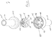
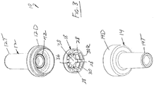
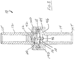
- the valve 10 of the invention comprises inlet housing 12 and an outlet housing 14 fastened, preferably permanently, together at joint 16 such as by welding or bonding.
- the inlet and outlet housing 12 & 14 include tube fittings 12T and 14T respectively; however, it shall be appreciated that the housing 12 & 14 may include other types of fittings such as a luer lock fitting without departing from the spirit and scope of this invention.
- one or both of the inlet and outlet housings 12 & 14 may be provided with barbed hose fittings, luer fittings or locking luer fitting (see the various embodiments in the Dome Check Valves of U.S. Patents 7,296,782 and 7,641,174 cited above).
- Both the inlet and outlet housing 12 & 14 further include a generally dome-shaped larger diameter configuration 12D and 14D respectively, that are appropriately configured to mate together to then be fastened at joint 16.
- an elastomeric dome-shaped valve element 18 is entrained between the dome-shaped larger diameter configurations 12D & 14D of the inlet and outlet housing 12 & 14.
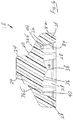
- the valve element 18 comprises a generally dome-shaped configuration 20 with a central integral stem 22, preferably frustoconical, positioned concentrically therewith that extends into the inlet housing 12.
- the central integral stem 22 comprises a star-shaped configuration with a plurality of equally-spaced radial projections 24 (e.g., 3 are shown respectively positioned at 120 degrees) to allow fluid flow therearound in the event the stem 22 is engaged by the tip of a luer fitting such as a syringe or other device that might otherwise form a seal therewith if the stem 22 was configured circular cylindrically.
- stem 22 may be employed without departing from the spirit and scope of this invention to preclude sealing with the tip of the access device, such as for example the slots and notches shown in the Dome Check Valves of U.S. Patents 7,296,782 and 7,641,174 cited above.
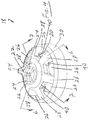
- the dome-shaped valve element 18 includes a plurality of equally-spaced cut-outs 26 (six are shown).
- the cut-outs 26 allow fluid flow therethrough thereby increasing the amount of fluid flow that may flow through the valve 10 when the valve element 18 is cracked open.
- the cut-outs 26 also streamline the fluid flow while minimizing the potential for air entrapment under the dome-shaped valve element 18.
- the generally dome-shaped configuration of the valve element 18 further comprises an integral annular skirt 30 extending about its periphery.
- the plurality of cut-outs 26 define a plurality of equally-spaced legs 28 (six are shown) extending generally radially outward then downwardly to merge into the annular skirt 30.
- the width of the legs 28 is defined by the width of the cut-outs 26, preferably to thereby define legs 28 having sufficient strength to achieve the desired cracking pressure (i.e., the heftier the legs 28 the quieter they will be to increase the amount of cracking pressure necessary to crack the valve element 18).
- each of the legs 28 comprise an outer side wall 32 sloping outwardly from the inlet at a first angle and an inner side wall 34 sloping outwardly from the inlet at a second angle greater than the first angle, thereby achieving a substantially thick configuration.
- the integral annular skirt 30 comprises a substantially thin configuration that serves to stabilize the legs 28 and keep them in their generally radial configuration relative to one another.
- the bottommost annular edge of the skirt 30 includes an inwardly extending rim 30R of increased thickness to provide additional stability.
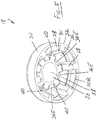
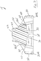
- Figs. 6 and 7 further illustrate the configuration of the underside of the dome-shaped valve element 18 as including a generally concave portion 36 extending circularly annularly about the underside to define an outwardly extending point 38 in the form of an upside-down three dimensional hyperbolic curve (i.e., similar to the curve of a single pole fabric tent).
- the concave portion 36 precludes the entrapment of air underneath the valve element 18 that might otherwise occur with the prior art dome check valves noted above.
- Fig. 6 and 7 further illustrate the configuration of the underside of the dome-shaped valve element 18 as including a generally concave portion 36 extending circularly annularly about the underside to define an outwardly extending point 38 in the form of an upside-down three dimensional hyperbolic curve (i.e., similar to the curve of a single pole fabric tent).
- the concave portion 36 precludes the entrapment of air underneath the valve element 18 that might otherwise occur with the prior art dome check valves noted above.
- the peripheral edges 36E of the concave portion 36 are rounded to blend into the cut-outs 26 and in doing so, as shown in Fig 6 , define undercuts 40 between the peripheral edges 36E and the legs 28 while further streamlining the fluid flow through the cut-outs 26.
- the undercuts 40 function as a living hinge to facilitate the dome-shaped valve element 18 moving inwardly during cracking in a precise, controlled manner while further streamlining the fluid flow around the otherwise sharp corners between the legs 28 and the peripheral edges 36E.
- the inside of the dome-shaped larger diameter configuration 12D of the inlet housing 12 comprises an annular valve seat 42 which forms a seal with the upper surface of the dome-shaped configuration 20 of the valve element 18 when the valve element 18 is in its at rest position within the housings 12 & 14.
- the inside of the dome-shaped larger-diameter configuration 14D of the outlet housing 14 comprises an annular seat 44 on which the inwardly extending rim 30R of the annular skirt 30 is seated when the valve element 18 is in its at rest position within the housings 12 & 14.
- the inside of the dome-shaped larger-diameter configuration 14D of the outlet housing 14 comprises a plurality of castellations 46 (four are shown) having an inside diameter that is appreciably less than the outside diameter of the hyperbolic curve defined by the concave portion 36 to limit the inward travel of the valve element 18 as it is cracked open. It is noted that the number of legs 28 versus the castellations 46 are preferably different.
- valve 10 In operation, at rest bidirectional fluid flow through the valve 10 is blocked by virtue of the seal formed between the annular valve seat 42 and the upper surface of the dome-shaped configuration 20 of the valve element 18 under the resilient force of the legs 28 and skirt 30.
- the valve 10 may be opened or "cracked” either by fluid pressure in its inlet housing 12 or by a physical object such as the tip of a syringe that exerts a force on the central integral stem 22 of the valve element 18 against the resilient force of the legs 28 and skirt 30. Once the valve element 18 is cracked opened, fluid flow from the inlet housing 12 flows around the stem 22 radially across the outer surface of the dome-shaped configuration 20 of the valve element 18, through the cut-outs 26 past the legs 28 and the castellations 46 and then out via outlet housing 14.
- the valve 10 a substantial flow of fluid is allowed to pass through the valve 10 once the valve element 18 is cracked.
- the cracking pressure is removed, either by the lack of sufficient pressure of the incoming fluid in inlet housing 12 or by removal of the object that cracked the valve 10, the inherent resiliency of the legs 28 and skirt 30 urges the dome-shaped configuration 20 of the valve element 18 back into sealing engagement with the annular valve seat 42 of the inlet housing 12.
- the sealing force caused therebetween is sufficient to assure an adequate seal even when there is no fluid pressure in the outlet housing 14.
- the dome-shaped configuration 20 of the valve element 18 is capable of remaining sealed even when significant back fluid pressure exits in the outlet housing 14.
- the limited travel of the dome-shaped configuration 20 coupled with its dome-shaped configuration 20, assures that the valve element 18 does not deform (i.e., is not blown out) even when very high pressures exist in the inlet housing 12.
Landscapes
- Engineering & Computer Science (AREA)
- Health & Medical Sciences (AREA)
- General Engineering & Computer Science (AREA)
- Heart & Thoracic Surgery (AREA)
- Mechanical Engineering (AREA)
- Hematology (AREA)
- Biomedical Technology (AREA)
- Life Sciences & Earth Sciences (AREA)
- Animal Behavior & Ethology (AREA)
- General Health & Medical Sciences (AREA)
- Public Health (AREA)
- Veterinary Medicine (AREA)
- Anesthesiology (AREA)
- Pulmonology (AREA)
- Check Valves (AREA)
Applications Claiming Priority (2)
| Application Number | Priority Date | Filing Date | Title |
|---|---|---|---|
| US201562151497P | 2015-04-23 | 2015-04-23 | |
| PCT/US2016/029242 WO2016172721A1 (en) | 2015-04-23 | 2016-04-25 | High pressure dome check valve |
Publications (3)
| Publication Number | Publication Date |
|---|---|
| EP3289251A1 EP3289251A1 (en) | 2018-03-07 |
| EP3289251A4 EP3289251A4 (en) | 2018-12-12 |
| EP3289251B1 true EP3289251B1 (en) | 2020-02-26 |
Family
ID=57144295
Family Applications (1)
| Application Number | Title | Priority Date | Filing Date |
|---|---|---|---|
| EP16784101.4A Active EP3289251B1 (en) | 2015-04-23 | 2016-04-25 | High pressure dome check valve |
Country Status (4)
| Country | Link |
|---|---|
| US (1) | US9976660B2 (enExample) |
| EP (1) | EP3289251B1 (enExample) |
| JP (1) | JP6609323B2 (enExample) |
| WO (1) | WO2016172721A1 (enExample) |
Families Citing this family (22)
| Publication number | Priority date | Publication date | Assignee | Title |
|---|---|---|---|---|
| US10441761B2 (en) | 2016-07-01 | 2019-10-15 | Boston Scientific Scimed, Inc. | Delivery devices and methods |
| CN115591066A (zh) | 2017-01-10 | 2023-01-13 | 波士顿科学国际有限公司(Us) | 用于输送粉末药剂的装置和方法 |
| US10786596B2 (en) | 2018-01-12 | 2020-09-29 | Boston Scientific Scimed, Inc. | Powder for achieving hemostasis |
| US11766546B2 (en) | 2018-01-31 | 2023-09-26 | Boston Scientific Scimed, Inc. | Apparatuses and methods for delivering powdered agents |
| US11001490B2 (en) * | 2018-04-10 | 2021-05-11 | Bericap Holding Gmbh | Extraction system from a closed loop system |
| US11229467B2 (en) * | 2018-04-11 | 2022-01-25 | Zimmer Gmbh | Valve for prefilled bone cement mixing system |
| CN117547720A (zh) | 2018-10-02 | 2024-02-13 | 波士顿科学国际有限公司 | 用于流体化和输送粉状剂的装置 |
| AU2019352968B2 (en) | 2018-10-02 | 2024-10-31 | Boston Scientific Scimed, Inc. | Devices for fluidization and delivering a powdered agent |
| EP3714919A1 (en) * | 2019-03-29 | 2020-09-30 | Fresenius Medical Care Deutschland GmbH | Reinfusion tube system, package and methods |
| CN121102700A (zh) | 2019-12-03 | 2025-12-12 | 波士顿科学国际有限公司 | 药剂施用医疗装置 |
| EP4017338B1 (en) | 2019-12-03 | 2024-01-31 | Boston Scientific Scimed, Inc. | Medical devices for agent delivery |
| WO2021113324A1 (en) | 2019-12-03 | 2021-06-10 | Boston Scientific Scimed, Inc. | Devices and methods for delivering powdered agents |
| EP4417233A3 (en) | 2019-12-03 | 2024-10-23 | Boston Scientific Scimed, Inc. | Medical devices for agent delivery |
| CN114845644A (zh) | 2019-12-20 | 2022-08-02 | 波士顿科学国际有限公司 | 药剂输送装置 |
| US12102749B2 (en) | 2020-01-06 | 2024-10-01 | Boston Scientific Scimed, Inc. | Agent delivery systems and methods of using the same |
| CN119971275A (zh) | 2020-01-06 | 2025-05-13 | 波士顿科学国际有限公司 | 用于输送粉末状药剂的装置 |
| US12083216B2 (en) | 2020-02-18 | 2024-09-10 | Boston Scientific Scimed, Inc. | Hemostatic compositions and related methods |
| EP4623837A3 (en) | 2020-03-06 | 2025-12-03 | Boston Scientific Scimed, Inc. | Devices for delivering powdered agents |
| JP7665646B2 (ja) | 2020-03-24 | 2025-04-21 | ボストン サイエンティフィック サイムド,インコーポレイテッド | 薬剤送達システム及びその使用方法 |
| KR20230007378A (ko) | 2020-04-17 | 2023-01-12 | 보스톤 싸이엔티픽 싸이메드 인코포레이티드 | 지혈 조성물 및 관련 방법 |
| CN111365602A (zh) * | 2020-04-23 | 2020-07-03 | 南京贝奇尔机械有限公司 | 一种快速卸荷橡胶阀盘 |
| WO2023192865A2 (en) * | 2022-03-29 | 2023-10-05 | Equilibar, Llc | Check valve and compact pump system |
Family Cites Families (21)
| Publication number | Priority date | Publication date | Assignee | Title |
|---|---|---|---|---|
| US3831629A (en) | 1972-01-24 | 1974-08-27 | Halkey Roberts Corp | Check valve |
| US4369812A (en) | 1981-02-18 | 1983-01-25 | Nypro Inc. | Control of fluid flow using precisely positioned disc |
| US4499916A (en) | 1983-01-31 | 1985-02-19 | Allied Corporation | Vacuum check valve |
| US4749003A (en) * | 1987-01-22 | 1988-06-07 | Filtertek, Inc. | Center flow check valve |
| US5349984A (en) | 1993-01-25 | 1994-09-27 | Halkey-Roberts Corporation | Check valve |
| US5509433A (en) * | 1993-10-13 | 1996-04-23 | Paradis; Joseph R. | Control of fluid flow |
| US5529278A (en) * | 1993-11-19 | 1996-06-25 | Novoste Corporation | Fluid access and flow control valve |
| US5573516A (en) * | 1995-09-18 | 1996-11-12 | Medical Connexions, Inc. | Needleless connector |
| DE19723648C1 (de) * | 1997-06-05 | 1998-08-27 | Disetronic Licensing Ag | Vorrichtung zur dosierten Verabreichung einer Medikamentflüssigkeit |
| US5899624A (en) * | 1997-09-08 | 1999-05-04 | Thompson; Edwin | Fluid dispensing valve |
| US5909747A (en) * | 1998-04-03 | 1999-06-08 | American Meter Company | Radial flow diaphragm valve |
| US5992462A (en) | 1998-10-28 | 1999-11-30 | Vernay Laboratories, Inc. | Disc type check valve |
| IT1311347B1 (it) | 1999-11-12 | 2002-03-12 | Borla Ind | Valvola di ritegno per linee medicali di infusione e simili. |
| ITMI20020819A1 (it) * | 2002-04-18 | 2003-10-20 | Gambro Lundia Ab | Elemento di connessione e dispositivo di collegamento per tubazioni ad uso medicale |
| US7296782B2 (en) * | 2004-10-01 | 2007-11-20 | Halkey-Roberts Corporation | Dome check valve |
| ATE428879T1 (de) * | 2005-11-12 | 2009-05-15 | Gea Tuchenhagen Gmbh | Doppelsitzventil |
| ITTO20070023A1 (it) * | 2007-01-17 | 2008-07-18 | Borla Ind | Valvola unidirezionale per linee medicali di infusione e simili |
| WO2009144599A1 (en) * | 2008-04-14 | 2009-12-03 | Elcam Medical A.C.S. Ltd | Luer tip activated flow control device |
| US9775980B2 (en) * | 2008-09-23 | 2017-10-03 | Hospi Corporation | Valved enteral administration assembly |
| AU2012271986A1 (en) * | 2011-06-22 | 2013-04-04 | Gambro Lundia Ab | Valve automatically opening on connection, and applications therefor |
| US9156569B2 (en) * | 2011-12-21 | 2015-10-13 | Berry Plastics Corporation | Pediatric dosing dispenser |
-
2016
- 2016-04-25 WO PCT/US2016/029242 patent/WO2016172721A1/en not_active Ceased
- 2016-04-25 EP EP16784101.4A patent/EP3289251B1/en active Active
- 2016-04-25 US US15/138,015 patent/US9976660B2/en active Active
- 2016-04-25 JP JP2017555389A patent/JP6609323B2/ja active Active
Non-Patent Citations (1)
| Title |
|---|
| None * |
Also Published As
| Publication number | Publication date |
|---|---|
| EP3289251A4 (en) | 2018-12-12 |
| WO2016172721A1 (en) | 2016-10-27 |
| JP2018513950A (ja) | 2018-05-31 |
| US9976660B2 (en) | 2018-05-22 |
| EP3289251A1 (en) | 2018-03-07 |
| JP6609323B2 (ja) | 2019-11-20 |
| US20160312910A1 (en) | 2016-10-27 |
Similar Documents
| Publication | Publication Date | Title |
|---|---|---|
| EP3289251B1 (en) | High pressure dome check valve | |
| US7296782B2 (en) | Dome check valve | |
| CN101990611B (zh) | 阀组件 | |
| US5462255A (en) | Automatic fluid control valve | |
| US7867204B2 (en) | Needleless access port valves | |
| US6062435A (en) | Valved dispensing system with priming liquid loss prevention | |
| EP3056448B1 (de) | Trinkbehälter mit einem Trinkaufsatz | |
| US5218993A (en) | Serviceable check valve | |
| US9861804B2 (en) | Compressible needleless valve assembly | |
| EP3119689B1 (en) | One-way valve for a compressible container and container with such a valve | |
| TW201805213A (zh) | 不可再充填式噴霧閥 | |
| US10408372B2 (en) | Fluid-connecting element | |
| WO2007027567A1 (en) | Medical fluid container system having needle-free connection | |
| AU2012200810B2 (en) | Dome Check Valve | |
| JP7356444B2 (ja) | キャップ付きコネクタ、キャップ、及びキャップ付きコネクタの使用方法 | |
| KR102152792B1 (ko) | 에코 펌프 방식 화장품 용기 | |
| HK1200745B (en) | Medical connectors and methods of use |
Legal Events
| Date | Code | Title | Description |
|---|---|---|---|
| STAA | Information on the status of an ep patent application or granted ep patent |
Free format text: STATUS: THE INTERNATIONAL PUBLICATION HAS BEEN MADE |
|
| PUAI | Public reference made under article 153(3) epc to a published international application that has entered the european phase |
Free format text: ORIGINAL CODE: 0009012 |
|
| STAA | Information on the status of an ep patent application or granted ep patent |
Free format text: STATUS: REQUEST FOR EXAMINATION WAS MADE |
|
| 17P | Request for examination filed |
Effective date: 20171127 |
|
| AK | Designated contracting states |
Kind code of ref document: A1 Designated state(s): AL AT BE BG CH CY CZ DE DK EE ES FI FR GB GR HR HU IE IS IT LI LT LU LV MC MK MT NL NO PL PT RO RS SE SI SK SM TR |
|
| AX | Request for extension of the european patent |
Extension state: BA ME |
|
| DAV | Request for validation of the european patent (deleted) | ||
| DAX | Request for extension of the european patent (deleted) | ||
| A4 | Supplementary search report drawn up and despatched |
Effective date: 20181109 |
|
| RIC1 | Information provided on ipc code assigned before grant |
Ipc: F16K 1/34 20060101AFI20181105BHEP Ipc: F16K 15/14 20060101ALI20181105BHEP Ipc: A61M 39/26 20060101ALI20181105BHEP Ipc: F16K 1/38 20060101ALI20181105BHEP Ipc: B65D 47/20 20060101ALI20181105BHEP Ipc: A61K 51/00 20060101ALI20181105BHEP Ipc: F16K 15/16 20060101ALI20181105BHEP Ipc: A61M 39/24 20060101ALI20181105BHEP |
|
| GRAP | Despatch of communication of intention to grant a patent |
Free format text: ORIGINAL CODE: EPIDOSNIGR1 |
|
| STAA | Information on the status of an ep patent application or granted ep patent |
Free format text: STATUS: GRANT OF PATENT IS INTENDED |
|
| INTG | Intention to grant announced |
Effective date: 20190429 |
|
| GRAJ | Information related to disapproval of communication of intention to grant by the applicant or resumption of examination proceedings by the epo deleted |
Free format text: ORIGINAL CODE: EPIDOSDIGR1 |
|
| STAA | Information on the status of an ep patent application or granted ep patent |
Free format text: STATUS: REQUEST FOR EXAMINATION WAS MADE |
|
| INTC | Intention to grant announced (deleted) | ||
| GRAS | Grant fee paid |
Free format text: ORIGINAL CODE: EPIDOSNIGR3 |
|
| STAA | Information on the status of an ep patent application or granted ep patent |
Free format text: STATUS: GRANT OF PATENT IS INTENDED |
|
| GRAP | Despatch of communication of intention to grant a patent |
Free format text: ORIGINAL CODE: EPIDOSNIGR1 |
|
| INTG | Intention to grant announced |
Effective date: 20191017 |
|
| GRAA | (expected) grant |
Free format text: ORIGINAL CODE: 0009210 |
|
| STAA | Information on the status of an ep patent application or granted ep patent |
Free format text: STATUS: THE PATENT HAS BEEN GRANTED |
|
| AK | Designated contracting states |
Kind code of ref document: B1 Designated state(s): AL AT BE BG CH CY CZ DE DK EE ES FI FR GB GR HR HU IE IS IT LI LT LU LV MC MK MT NL NO PL PT RO RS SE SI SK SM TR |
|
| REG | Reference to a national code |
Ref country code: GB Ref legal event code: FG4D |
|
| REG | Reference to a national code |
Ref country code: CH Ref legal event code: EP |
|
| REG | Reference to a national code |
Ref country code: AT Ref legal event code: REF Ref document number: 1238033 Country of ref document: AT Kind code of ref document: T Effective date: 20200315 |
|
| REG | Reference to a national code |
Ref country code: IE Ref legal event code: FG4D |
|
| REG | Reference to a national code |
Ref country code: DE Ref legal event code: R096 Ref document number: 602016030681 Country of ref document: DE |
|
| PG25 | Lapsed in a contracting state [announced via postgrant information from national office to epo] |
Ref country code: NO Free format text: LAPSE BECAUSE OF FAILURE TO SUBMIT A TRANSLATION OF THE DESCRIPTION OR TO PAY THE FEE WITHIN THE PRESCRIBED TIME-LIMIT Effective date: 20200526 Ref country code: FI Free format text: LAPSE BECAUSE OF FAILURE TO SUBMIT A TRANSLATION OF THE DESCRIPTION OR TO PAY THE FEE WITHIN THE PRESCRIBED TIME-LIMIT Effective date: 20200226 Ref country code: RS Free format text: LAPSE BECAUSE OF FAILURE TO SUBMIT A TRANSLATION OF THE DESCRIPTION OR TO PAY THE FEE WITHIN THE PRESCRIBED TIME-LIMIT Effective date: 20200226 |
|
| REG | Reference to a national code |
Ref country code: NL Ref legal event code: MP Effective date: 20200226 |
|
| REG | Reference to a national code |
Ref country code: LT Ref legal event code: MG4D |
|
| PG25 | Lapsed in a contracting state [announced via postgrant information from national office to epo] |
Ref country code: BG Free format text: LAPSE BECAUSE OF FAILURE TO SUBMIT A TRANSLATION OF THE DESCRIPTION OR TO PAY THE FEE WITHIN THE PRESCRIBED TIME-LIMIT Effective date: 20200526 Ref country code: LV Free format text: LAPSE BECAUSE OF FAILURE TO SUBMIT A TRANSLATION OF THE DESCRIPTION OR TO PAY THE FEE WITHIN THE PRESCRIBED TIME-LIMIT Effective date: 20200226 Ref country code: IS Free format text: LAPSE BECAUSE OF FAILURE TO SUBMIT A TRANSLATION OF THE DESCRIPTION OR TO PAY THE FEE WITHIN THE PRESCRIBED TIME-LIMIT Effective date: 20200626 Ref country code: SE Free format text: LAPSE BECAUSE OF FAILURE TO SUBMIT A TRANSLATION OF THE DESCRIPTION OR TO PAY THE FEE WITHIN THE PRESCRIBED TIME-LIMIT Effective date: 20200226 Ref country code: GR Free format text: LAPSE BECAUSE OF FAILURE TO SUBMIT A TRANSLATION OF THE DESCRIPTION OR TO PAY THE FEE WITHIN THE PRESCRIBED TIME-LIMIT Effective date: 20200527 Ref country code: HR Free format text: LAPSE BECAUSE OF FAILURE TO SUBMIT A TRANSLATION OF THE DESCRIPTION OR TO PAY THE FEE WITHIN THE PRESCRIBED TIME-LIMIT Effective date: 20200226 |
|
| PG25 | Lapsed in a contracting state [announced via postgrant information from national office to epo] |
Ref country code: NL Free format text: LAPSE BECAUSE OF FAILURE TO SUBMIT A TRANSLATION OF THE DESCRIPTION OR TO PAY THE FEE WITHIN THE PRESCRIBED TIME-LIMIT Effective date: 20200226 |
|
| PG25 | Lapsed in a contracting state [announced via postgrant information from national office to epo] |
Ref country code: CZ Free format text: LAPSE BECAUSE OF FAILURE TO SUBMIT A TRANSLATION OF THE DESCRIPTION OR TO PAY THE FEE WITHIN THE PRESCRIBED TIME-LIMIT Effective date: 20200226 Ref country code: SK Free format text: LAPSE BECAUSE OF FAILURE TO SUBMIT A TRANSLATION OF THE DESCRIPTION OR TO PAY THE FEE WITHIN THE PRESCRIBED TIME-LIMIT Effective date: 20200226 Ref country code: DK Free format text: LAPSE BECAUSE OF FAILURE TO SUBMIT A TRANSLATION OF THE DESCRIPTION OR TO PAY THE FEE WITHIN THE PRESCRIBED TIME-LIMIT Effective date: 20200226 Ref country code: LT Free format text: LAPSE BECAUSE OF FAILURE TO SUBMIT A TRANSLATION OF THE DESCRIPTION OR TO PAY THE FEE WITHIN THE PRESCRIBED TIME-LIMIT Effective date: 20200226 Ref country code: EE Free format text: LAPSE BECAUSE OF FAILURE TO SUBMIT A TRANSLATION OF THE DESCRIPTION OR TO PAY THE FEE WITHIN THE PRESCRIBED TIME-LIMIT Effective date: 20200226 Ref country code: SM Free format text: LAPSE BECAUSE OF FAILURE TO SUBMIT A TRANSLATION OF THE DESCRIPTION OR TO PAY THE FEE WITHIN THE PRESCRIBED TIME-LIMIT Effective date: 20200226 Ref country code: RO Free format text: LAPSE BECAUSE OF FAILURE TO SUBMIT A TRANSLATION OF THE DESCRIPTION OR TO PAY THE FEE WITHIN THE PRESCRIBED TIME-LIMIT Effective date: 20200226 Ref country code: PT Free format text: LAPSE BECAUSE OF FAILURE TO SUBMIT A TRANSLATION OF THE DESCRIPTION OR TO PAY THE FEE WITHIN THE PRESCRIBED TIME-LIMIT Effective date: 20200719 Ref country code: ES Free format text: LAPSE BECAUSE OF FAILURE TO SUBMIT A TRANSLATION OF THE DESCRIPTION OR TO PAY THE FEE WITHIN THE PRESCRIBED TIME-LIMIT Effective date: 20200226 |
|
| REG | Reference to a national code |
Ref country code: AT Ref legal event code: MK05 Ref document number: 1238033 Country of ref document: AT Kind code of ref document: T Effective date: 20200226 |
|
| REG | Reference to a national code |
Ref country code: DE Ref legal event code: R097 Ref document number: 602016030681 Country of ref document: DE |
|
| PLBE | No opposition filed within time limit |
Free format text: ORIGINAL CODE: 0009261 |
|
| STAA | Information on the status of an ep patent application or granted ep patent |
Free format text: STATUS: NO OPPOSITION FILED WITHIN TIME LIMIT |
|
| PG25 | Lapsed in a contracting state [announced via postgrant information from national office to epo] |
Ref country code: AT Free format text: LAPSE BECAUSE OF FAILURE TO SUBMIT A TRANSLATION OF THE DESCRIPTION OR TO PAY THE FEE WITHIN THE PRESCRIBED TIME-LIMIT Effective date: 20200226 Ref country code: IT Free format text: LAPSE BECAUSE OF FAILURE TO SUBMIT A TRANSLATION OF THE DESCRIPTION OR TO PAY THE FEE WITHIN THE PRESCRIBED TIME-LIMIT Effective date: 20200226 |
|
| 26N | No opposition filed |
Effective date: 20201127 |
|
| PG25 | Lapsed in a contracting state [announced via postgrant information from national office to epo] |
Ref country code: PL Free format text: LAPSE BECAUSE OF FAILURE TO SUBMIT A TRANSLATION OF THE DESCRIPTION OR TO PAY THE FEE WITHIN THE PRESCRIBED TIME-LIMIT Effective date: 20200226 Ref country code: SI Free format text: LAPSE BECAUSE OF FAILURE TO SUBMIT A TRANSLATION OF THE DESCRIPTION OR TO PAY THE FEE WITHIN THE PRESCRIBED TIME-LIMIT Effective date: 20200226 |
|
| PG25 | Lapsed in a contracting state [announced via postgrant information from national office to epo] |
Ref country code: TR Free format text: LAPSE BECAUSE OF FAILURE TO SUBMIT A TRANSLATION OF THE DESCRIPTION OR TO PAY THE FEE WITHIN THE PRESCRIBED TIME-LIMIT Effective date: 20200226 Ref country code: CY Free format text: LAPSE BECAUSE OF FAILURE TO SUBMIT A TRANSLATION OF THE DESCRIPTION OR TO PAY THE FEE WITHIN THE PRESCRIBED TIME-LIMIT Effective date: 20200226 |
|
| PG25 | Lapsed in a contracting state [announced via postgrant information from national office to epo] |
Ref country code: MK Free format text: LAPSE BECAUSE OF FAILURE TO SUBMIT A TRANSLATION OF THE DESCRIPTION OR TO PAY THE FEE WITHIN THE PRESCRIBED TIME-LIMIT Effective date: 20200226 Ref country code: AL Free format text: LAPSE BECAUSE OF FAILURE TO SUBMIT A TRANSLATION OF THE DESCRIPTION OR TO PAY THE FEE WITHIN THE PRESCRIBED TIME-LIMIT Effective date: 20200226 |
|
| PGFP | Annual fee paid to national office [announced via postgrant information from national office to epo] |
Ref country code: MC Payment date: 20240409 Year of fee payment: 9 |
|
| PGFP | Annual fee paid to national office [announced via postgrant information from national office to epo] |
Ref country code: MT Payment date: 20240402 Year of fee payment: 9 |
|
| PGFP | Annual fee paid to national office [announced via postgrant information from national office to epo] |
Ref country code: LU Payment date: 20250418 Year of fee payment: 10 |
|
| PGFP | Annual fee paid to national office [announced via postgrant information from national office to epo] |
Ref country code: DE Payment date: 20250422 Year of fee payment: 10 |
|
| PGFP | Annual fee paid to national office [announced via postgrant information from national office to epo] |
Ref country code: GB Payment date: 20250423 Year of fee payment: 10 |
|
| PGFP | Annual fee paid to national office [announced via postgrant information from national office to epo] |
Ref country code: BE Payment date: 20250418 Year of fee payment: 10 |
|
| PGFP | Annual fee paid to national office [announced via postgrant information from national office to epo] |
Ref country code: FR Payment date: 20250425 Year of fee payment: 10 |
|
| PGFP | Annual fee paid to national office [announced via postgrant information from national office to epo] |
Ref country code: CH Payment date: 20250501 Year of fee payment: 10 |
|
| PGFP | Annual fee paid to national office [announced via postgrant information from national office to epo] |
Ref country code: IE Payment date: 20250422 Year of fee payment: 10 |