EP3288770B2 - Sicherheitselement mit mehrschichtstruktur - Google Patents
Sicherheitselement mit mehrschichtstruktur Download PDFInfo
- Publication number
- EP3288770B2 EP3288770B2 EP16716825.1A EP16716825A EP3288770B2 EP 3288770 B2 EP3288770 B2 EP 3288770B2 EP 16716825 A EP16716825 A EP 16716825A EP 3288770 B2 EP3288770 B2 EP 3288770B2
- Authority
- EP
- European Patent Office
- Prior art keywords
- layer
- security element
- security
- dielectric
- element according
- Prior art date
- Legal status (The legal status is an assumption and is not a legal conclusion. Google has not performed a legal analysis and makes no representation as to the accuracy of the status listed.)
- Active
Links
Images
Classifications
-
- B—PERFORMING OPERATIONS; TRANSPORTING
- B42—BOOKBINDING; ALBUMS; FILES; SPECIAL PRINTED MATTER
- B42D—BOOKS; BOOK COVERS; LOOSE LEAVES; PRINTED MATTER CHARACTERISED BY IDENTIFICATION OR SECURITY FEATURES; PRINTED MATTER OF SPECIAL FORMAT OR STYLE NOT OTHERWISE PROVIDED FOR; DEVICES FOR USE THEREWITH AND NOT OTHERWISE PROVIDED FOR; MOVABLE-STRIP WRITING OR READING APPARATUS
- B42D25/00—Information-bearing cards or sheet-like structures characterised by identification or security features; Manufacture thereof
- B42D25/30—Identification or security features, e.g. for preventing forgery
-
- B—PERFORMING OPERATIONS; TRANSPORTING
- B42—BOOKBINDING; ALBUMS; FILES; SPECIAL PRINTED MATTER
- B42D—BOOKS; BOOK COVERS; LOOSE LEAVES; PRINTED MATTER CHARACTERISED BY IDENTIFICATION OR SECURITY FEATURES; PRINTED MATTER OF SPECIAL FORMAT OR STYLE NOT OTHERWISE PROVIDED FOR; DEVICES FOR USE THEREWITH AND NOT OTHERWISE PROVIDED FOR; MOVABLE-STRIP WRITING OR READING APPARATUS
- B42D25/00—Information-bearing cards or sheet-like structures characterised by identification or security features; Manufacture thereof
- B42D25/20—Information-bearing cards or sheet-like structures characterised by identification or security features; Manufacture thereof characterised by a particular use or purpose
- B42D25/29—Securities; Bank notes
-
- B—PERFORMING OPERATIONS; TRANSPORTING
- B42—BOOKBINDING; ALBUMS; FILES; SPECIAL PRINTED MATTER
- B42D—BOOKS; BOOK COVERS; LOOSE LEAVES; PRINTED MATTER CHARACTERISED BY IDENTIFICATION OR SECURITY FEATURES; PRINTED MATTER OF SPECIAL FORMAT OR STYLE NOT OTHERWISE PROVIDED FOR; DEVICES FOR USE THEREWITH AND NOT OTHERWISE PROVIDED FOR; MOVABLE-STRIP WRITING OR READING APPARATUS
- B42D25/00—Information-bearing cards or sheet-like structures characterised by identification or security features; Manufacture thereof
- B42D25/30—Identification or security features, e.g. for preventing forgery
- B42D25/351—Translucent or partly translucent parts, e.g. windows
-
- B—PERFORMING OPERATIONS; TRANSPORTING
- B42—BOOKBINDING; ALBUMS; FILES; SPECIAL PRINTED MATTER
- B42D—BOOKS; BOOK COVERS; LOOSE LEAVES; PRINTED MATTER CHARACTERISED BY IDENTIFICATION OR SECURITY FEATURES; PRINTED MATTER OF SPECIAL FORMAT OR STYLE NOT OTHERWISE PROVIDED FOR; DEVICES FOR USE THEREWITH AND NOT OTHERWISE PROVIDED FOR; MOVABLE-STRIP WRITING OR READING APPARATUS
- B42D25/00—Information-bearing cards or sheet-like structures characterised by identification or security features; Manufacture thereof
- B42D25/30—Identification or security features, e.g. for preventing forgery
- B42D25/36—Identification or security features, e.g. for preventing forgery comprising special materials
- B42D25/373—Metallic materials
-
- B—PERFORMING OPERATIONS; TRANSPORTING
- B42—BOOKBINDING; ALBUMS; FILES; SPECIAL PRINTED MATTER
- B42D—BOOKS; BOOK COVERS; LOOSE LEAVES; PRINTED MATTER CHARACTERISED BY IDENTIFICATION OR SECURITY FEATURES; PRINTED MATTER OF SPECIAL FORMAT OR STYLE NOT OTHERWISE PROVIDED FOR; DEVICES FOR USE THEREWITH AND NOT OTHERWISE PROVIDED FOR; MOVABLE-STRIP WRITING OR READING APPARATUS
- B42D25/00—Information-bearing cards or sheet-like structures characterised by identification or security features; Manufacture thereof
- B42D25/40—Manufacture
- B42D25/45—Associating two or more layers
- B42D25/465—Associating two or more layers using chemicals or adhesives
Definitions
- the invention relates to a security element for security papers, value documents or the like, which consists of an interference-capable, multilayer structure, wherein the interference-capable, multilayer structure has a reflection layer, a dielectric layer and a partially transparent layer, wherein the dielectric layer is arranged between the reflection layer and the partially transparent layer.
- a generic security element is, for example, from the WO 2005/108110 A1 or the WO 2005/038136 A1 known.
- the viewer perceives a certain color that changes as the viewing angle changes.
- the color shift is caused by an interference effect between the light rays reflected from the surface of the outer partially transparent layer and the light rays that pass through the outer partially transparent and middle dielectric layers and are reflected back to the partially transparent layer by the reflective layer.
- the light rays are then either transmitted outwards or reflected again at the partially transparent layer, so that in this case the light rays are reflected back and forth between the reflective layer and the partially transparent layer several times.
- the light rays that have passed through the thin film layer have therefore traveled a longer path than the light rays reflected on the surface of the thin film layer, so that they are phase-shifted relative to them when they interfere with them. If the light rays incident on the thin film layer hit the thin film layer at different angles of incidence, the path traveled by the light rays in the thin film layer is of different lengths. This difference results from the path difference of the rays reflected multiple times within the thin film layer, which is changed by the angle of incidence. The phase position of the interfering light rays therefore varies depending on the angle of incidence, so that depending on the angle of incidence, different colors or shades of the resulting light beam perceived by the observer result, a so-called color shift effect.
- Such a generic security element is also referred to as a thin film layer interference layer structure or color shift element due to the way it works.
- the invention is therefore based on the object of developing a generic security element in such a way that the disadvantages of the prior art are eliminated and the protection against counterfeiting is further increased.
- the reflection layer of the interference-capable, multilayer structure is formed by a color layer or a further multilayer structure, wherein the color layer and the multilayer structure are designed such that they show a metallic color tone in incident light and a colorful color tone in transmitted light.
- a color layer with a metallic color tone is a color layer which has a metallically reflective surface with a metallic color tone, which is preferably golden, silver or bronze.
- a color layer with a colorful shade is a color layer which has a single or multi-colored surface, preferably a single-color blue, a single-color green or a single-color red.
- Transmitted light occurs when an object is illuminated from one side and viewed from the other. Incident light occurs when an object is illuminated and viewed from the same side.
- the color layer contains platelet-shaped metallic particles whose longest edge length is 15 nm to 1000 nm and whose thickness is 2 nm to 100 nm, so that the color layer has a golden color in reflected light and a blue color in transmitted light.
- the platelet-shaped metallic particles preferably have a longest edge length of 15 nm to 600 nm and particularly preferably 20 nm to 500 nm and a thickness of 2 nm to 40 nm and particularly preferably 4 nm to 30 nm.
- a color layer is for example made of WO 2011/064162 A2 and is also called gold-blue color.
- the invention thus replaces the reflective layer of a color shift element known from the prior art with a color layer with platelet-shaped metallic particles or with a further multilayer structure made up of at least two semi-transparent mirror layers and at least one dielectric layer arranged between the at least two mirror layers.
- reflected light both the color layer with platelet-shaped metallic particles and the further multilayer structure show a golden color tone, thus reflect the incident light and act like a reflective layer.
- the security element according to the invention therefore shows the color shift effect known from the prior art in reflected light.
- transmitted light however, both the color layer with platelet-shaped metallic particles and the further multilayer structure show a blue color tone and do not reflect the incident light or only reflect it insignificantly.
- the security element according to the invention therefore shows a blue color tone and no color shift effect.
- At least one of the dielectric layers of the interference-capable, multilayer structure is made of silicon dioxide (SiO2).
- the partially permeable layer of the interference-capable, multilayer structure preferably consists of at least chromium and/or nickel in the embodiment according to claim 1 and at least chromium and/or nickel in the embodiment according to claim 3.
- a dielectric layer can consist of a transparent printed layer that has a constant thickness.
- the invention further relates to a see-through security element for security papers, value documents and the like, with a carrier and a security element according to the invention applied to the carrier.
- a carrier is in particular a transparent or translucent plastic film.
- a lacquer layer can be arranged between the security element and the carrier, which preferably consists of an embossing lacquer.
- an embossing lacquer can be, for example, a UV lacquer, i.e. a lacquer that hardens under the influence of ultraviolet light, or a thermoplastic embossing lacquer. Diffractive structures, holograms or micromirrors are preferably embossed into this embossing lacquer.
- the thickness of this lacquer layer is 1 ⁇ m to 12 ⁇ m, preferably 2 ⁇ m to 7 ⁇ m.
- Translucency in the sense of this invention means that an object, such as the substrate or the plastic film, allows a certain proportion of incident light to pass through. If light hits one side of the object, a certain proportion of the light is allowed to pass through to the other side of the object and exits there again. The greater the percentage of light passing through, based on the incident light, the more translucent the object is. If the percentage is at least 90%, i.e. the object allows the incident light to pass through almost unattenuated, like a window, the object is referred to as transparent. On the other hand, an object that allows less than 10% and preferably about 0% of the incident light to pass through, i.e. where the proportion of light passing through, based on the incident light, is low or close to or equal to zero, is referred to as opaque or non-transparent.
- a security paper, value document or the like particularly preferably consists of a substrate made of paper made of cotton fibers, as is used for banknotes, for example, or of other natural fibers or of synthetic fibers or a mixture of natural and synthetic fibers, or of at least one plastic film.
- the substrate also preferably consists of a combination of at least two different substrates arranged one above the other and connected to one another, a so-called hybrid.
- the substrate here consists, for example, of a combination of plastic film-paper-plastic film, i.e. a substrate made of paper is covered on each of its two sides by a plastic film, or of a combination of paper-plastic film-paper, i.e. a substrate made of a plastic film is covered on each of its two sides by paper.
- the document DE 102 43 653 A9 states in particular that the paper layer usually has a weight of 50 g/m 2 to 100 g/m 2 , preferably 80 g/m 2 to 90 g/m 2 .
- the paper layer usually has a weight of 50 g/m 2 to 100 g/m 2 , preferably 80 g/m 2 to 90 g/m 2 .
- any other suitable weight can be used depending on the application.
- Security papers, value documents or the like in which a security element according to the invention can be used are in particular Banknotes, shares, bonds, certificates, vouchers, cheques, high-value tickets, but also other papers at risk of counterfeiting, such as passports and other identification documents, as well as cards, such as credit or debit cards, whose card body has at least one layer of security paper and also product security elements, such as labels, seals, packaging and the like.
- value document includes all of the above-mentioned materials, documents and product security devices.
- front or “back” of a substrate, security paper or value document are relative terms that can also be referred to as “one” and “the opposite" side and that make up the majority of the total surface of the substrate, security paper or value document. These terms expressly do not include the side surfaces of a substrate, security paper or value document, which are negligible when the thickness of a substrate or value document is only about one millimeter for card bodies or only fractions of a millimeter for banknotes, and which usually cannot or will not be provided with security elements or coatings. In particular, see-through effects cannot be achieved with the side surfaces.
- the security element according to the invention shows a viewer information in reflected light and in transmitted light.
- Information in the sense of this invention is a patterned and visually perceptible coating. This can, for example, form a graphic image, a picture, a number, a letter, text or other characters.
- the information particularly preferably consists of positive and/or negative motifs.
- a motif element itself is applied to the substrate, whereas in the case of a negative motif, the area surrounding the motif element is applied to the substrate.
- a positive motif is, for example, a letter printed in dark color on the light substrate.
- a negative motif is, for example, an area applied to the substrate in dark color, which has an unprinted area in the form of a letter within the area.
- the advantages of the invention are explained using the following exemplary embodiments and the supplementary figures.
- the exemplary embodiments represent preferred embodiments, to which the invention is not intended to be limited in any way.
- the representations in the figures are highly schematic for the sake of better understanding and do not reflect the real conditions.
- the proportions shown in the figures do not correspond to the conditions in reality and serve solely to improve clarity.
- the embodiments described in the following exemplary embodiments are reduced to the essential core information for the sake of better comprehensibility. In practical implementation, much more complex patterns or images can be used.
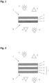
- Fig.1 shows a side view of a security element according to the invention with a partially transparent layer 3 and a reflection layer 1, between which a dielectric layer 2 is arranged. These three layers together form a thin film layer interference layer structure.
- the reflection layer 1 consists of a color layer that contains platelet-shaped metallic particles whose longest edge length is 15 nm to 1000 nm and whose thickness is 2 nm to 100 nm, so that this color layer shows a golden color in incident light and a blue color in transmitted light.
- a viewer 9 who looks at the security element from the front side 7 of the security element looks at the partially transparent layer 3 of the interference-capable, multi-layer structure.
- the viewer 9 therefore sees a color shift effect in incident light, i.e. with illumination 11 from the front side 7, in which the color of the security element changes from purple to green, for example, when the security element is tilted.
- incident light i.e. with illumination 11 from the front side 7
- the color shift effect disappears and the viewer 9 sees the security element in a blue color.
- a viewer 10 who looks at the security element from the back 8 of the security element looks at the color layer with platelet-shaped metallic particles.
- the viewer 9 thus sees the security element in a golden color in incident light, ie with an illumination 12 from the back 8, and the security element in a blue color in transmitted light, ie with an illumination 11 from the front 7. Color.
- Fig. 2 shows a side view of a security element according to the invention, in which the reflection layer 1, in contrast to the security element made of Fig.1 consists of a further multi-layer structure which has two semi-transparent mirror layers 4 and 6 and at least one dielectric layer 5 arranged between the two mirror layers.
- the two semi-transparent mirror layers 4 and 6 preferably each consist of a thin layer of aluminum and the dielectric layer 5 of SiO 2 .
- the same effect is obtained in incident and transmitted light from both the front side 7 and the back side 8 as for the observer from Fig.1 .
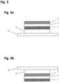
- Fig.3 shows the security element according to the invention Fig.1 , which is attached to a carrier 16 with a lacquer layer 15.
- the lacquer layer 15 preferably consists of a UV lacquer, the carrier 16 preferably of a plastic film.
- the security element with the reflective layer 1 is attached to the carrier 16 via the lacquer layer 15 and according to Fig. 3b with the partially permeable layer 3.
Landscapes
- Engineering & Computer Science (AREA)
- Manufacturing & Machinery (AREA)
- General Chemical & Material Sciences (AREA)
- Health & Medical Sciences (AREA)
- General Health & Medical Sciences (AREA)
- Toxicology (AREA)
- Chemical Kinetics & Catalysis (AREA)
- Chemical & Material Sciences (AREA)
- Business, Economics & Management (AREA)
- Accounting & Taxation (AREA)
- Finance (AREA)
- Credit Cards Or The Like (AREA)
- Laminated Bodies (AREA)
- Optical Filters (AREA)
Description
- Die Erfindung betrifft ein Sicherheitselement für Sicherheitspapiere, Wertdokumente oder dergleichen, das aus einem interferenzfähigen, mehrschichtigen Aufbau besteht, wobei der interferenzfähige, mehrschichtige Aufbau eine Reflexionsschicht, eine dielektrische Schicht und eine teildurchlässige Schicht aufweist, wobei die dielektrische Schicht zwischen der Reflexionsschicht und der teildurchlässigen Schicht angeordnet ist.
- Ein gattungsgemäßes Sicherheitselement ist beispielsweise aus der
WO 2005/108110 A1 oder derWO 2005/038136 A1 bekannt. - Wird das gattungsgemäße Sicherheitselement von der Seite der teildurchlässigen Schicht aus betrachtet, nimmt der Betrachter eine bestimmte Farbe wahr, die sich mit Änderung des Betrachtungswinkels ändert. Ursache der Farbverschiebung ist ein Interferenzeffekt zwischen den Lichtstrahlen, die von der Oberfläche der äußeren teildurchlässigen Schicht reflektiert werden, und den Lichtstrahlen, die durch die äußere teildurchlässige und die mittlere dielektrische Schicht hindurchtreten und von der Reflexionsschicht zu der teildurchlässigen Schicht zurückreflektiert werden. An der teildurchlässigen Schicht werden die Lichtstrahlen daraufhin entweder nach außen transmittiert oder wieder reflektiert, so dass in diesem Fall die Lichtstrahlen mehrfach zwischen der Reflexionsschicht und der teildurchlässigen Schicht hin- und herreflektiert werden. Somit haben die Lichtstrahlen, die durch die Dünnfilmschicht hindurchgetreten sind, einen längeren Weg zurückgelegt als die auf der Oberfläche der Dünnfilmschicht reflektierten Lichtstrahlen, so dass sie gegenüber diesen phasenverschoben sind, wenn sie mit ihnen interferieren. Treffen die auf die Dünnfilmschicht einfallenden Lichtstrahlen mit unterschiedlichen Einfallswinkeln auf die Dünnfilmschicht auf, ist der in der Dünnfilmschicht zurückgelegte Weg der Lichtstrahlen unterschiedlich lang. Dieser Unterschied resultiert aus der durch den Einfallswinkel geänderten Wegdifferenz der mehrfach innerhalb der Dünnfilmschicht reflektierten Strahlen. Deshalb ist die Phasenlage der interferierenden Lichtstrahlen je nach Einfallswinkel unterschiedlich, so dass sich je nach Einfallswinkel unterschiedliche Farben oder Farbtöne des resultierenden, vom Beobachter wahrgenommenen Lichtstrahls ergeben, ein sogenannter Farbkippeffekt. Ein derartiges gattungsgemäßes Sicherheitselement wird aufgrund seiner Wirkungsweise auch als Dünnfilmschicht-Interferenzschicht-Aufbau oder als Color-Shift-Element bezeichnet.
- Zur Erzeugung von unterschiedlichen optisch variablen Effekten bei einem gattungsgemäßen Sicherheitselement in Aufsicht und in Durchsicht ist es beispielsweise aus der
WO 2009/149831 A2 bekannt, in die teildurchlässige Schicht und die reflektierende Schicht eine Vielzahl von Aussparungen einzubringen. Diese Sicherheitselemente sind jedoch vergleichsweise aufwendig in der Herstellung und erzeugen in Durchlicht, von der Rückseite aus betrachtet, lediglich einen einheitlichen grauen Farbton - Das Patentdokument
EP 2 708 371 A1 offenbart ein Sicherheitselement mit den Merkmalen der Präambeln der Ansprüche 1 und 3. - Der Erfindung liegt deshalb die Aufgabe zugrunde, ein gattungsgemäßes Sicherheitselement derart weiterzubilden, dass die Nachteile des Standes der Technik behoben und der Schutz gegenüber Fälschungen weiter erhöht wird.
- Diese Aufgabe wird durch die Merkmale der unabhängigen Ansprüche gelöst. Weiterbildungen der Erfindung sind Gegenstand der abhängigen Ansprüche.
- Erfindungsgemäß wird die Reflexionsschicht des interferenzfähigen, mehrschichtigen Aufbaus durch eine Farbschicht oder einen weiteren mehrschichtigen Aufbau gebildet, wobei die Farbschicht und der mehrschichtige Aufbau derart ausgestaltet sind, dass sie in Auflicht einen metallischen Farbton und in Durchlicht einen bunten Farbton zeigen.
- Als Farbschicht mit einem metallischen Farbton wird im Sinne dieser Erfindung eine Farbschicht bezeichnet, die eine metallisch spiegelnde Oberfläche mit einem metallfarbenen Farbton aufweist, der bevorzugt golden bzw. goldfarben, silbern bzw. silberfarben oder bronzefarben ist.
- Als Farbschicht mit einem bunten Farbton wird im Sinne dieser Erfindung ein Farbschicht bezeichnet, die eine ein- oder mehrfarbige Oberfläche aufweist, bevorzugt eine einfarbig blaue, eine einfarbig grüne oder eine einfarbig rote.
- Durchlicht liegt hierbei vor, wenn die Beleuchtung eines Gegenstands von der einen Seite und die Betrachtung von der anderen Seite erfolgt. Auflicht liegt vor, wenn die Beleuchtung und Betrachtung von derselben Seite eines Gegenstands aus erfolgen.
- Wird die Reflexionsschicht durch eine Farbschicht gebildet, dann enthält die Farbschicht plättchenförmige metallische Partikel, deren längste Kantenlänge 15 nm bis 1000 nm und deren Dicke 2 nm bis 100 nm beträgt, so dass die Farbschicht in Auflicht einen goldenen Farbton und in Durchlicht einen blauen Farbton zeigt. Bevorzugt weisen die plättchenförmigen metallischen Partikel eine längste Kantenlänge von 15 nm bis 600 nm und besonders bevorzugt 20 nm bis 500 nm auf und eine Dicke von 2 nm bis 40 nm und besonders bevorzugt 4 nm bis 30 nm auf. Eine derartige Farbschicht ist beispielsweise aus der
WO 2011/064162 A2 bekannt und wird auch als Gold-Blau-Farbe bezeichnet. - Wird die Reflexionsschicht hingegen durch einen weiteren mehrschichtigen Aufbau gebildet, dann weist der weitere mehrschichtige Aufbau mindestens zwei semitransparente Spiegelschichten und mindestens eine zwischen den mindestens zwei Spiegelschichten angeordnete dielektrische Schicht auf, wie er beispielsweise aus der
DE 10 2009 058 243 A1 bekannt ist, so dass das Sicherheitselement aus einem interferenzfähigen, mehrschichtigen Aufbau aus mindestens fünf übereinander angeordneten Schichten besteht. Die Reflexionsschicht zeigt hierbei bei Messung der Transmission von unpolarisiertem Licht im blauen Wellenlängenbereich von 420 nm bis 490 nm eine Resonanz mit einer Halbwertsbreite von 70 nm bis 150 nm. Bevorzugt ist die Resonanz der Reflexionsschicht die einzige Resonanz im sichtbaren Bereich. Die mindestens zwei semitransparenten Spiegelschichten der Reflexionsschicht sind gebildet aus: - Aluminium oder einer Aluminium-Legierung, wobei die dielektrische Abstandsschicht mit einer Dicke h und einem Brechungsindex v die Relation 120 nm < h ·v < 190 nm erfüllt oder
- Silber oder einer Silber-Legierung, wobei die dielektrische Abstandsschicht mit einer Dicke h und einem Brechungsindex v die Relation 120 nm < h ·v < 170 nm oder 340 nm < h ·v < 400 nm erfüllt.
- Weitere Ausführungsformen und konkrete Dickenangaben zu den verwendeten Schichten des weiteren mehrschichtigen Aufbaus sind aus der
DE 10 2009 058 243 A1 bekannt, auf die hiermit verwiesen wird. - Die Erfindung ersetzt somit die Reflexionsschicht eines aus dem Stand der Technik bekannten Color-Shift-Elements durch eine Farbschicht mit plättchenförmigen metallischen Partikeln oder durch einen weiteren mehrschichtigen Aufbau aus mindestens zwei semitransparenten Spiegelschichten und mindestens einer zwischen den mindestens zwei Spiegelschichten angeordneten dielektrischen Schicht. In Auflicht zeigen sowohl die Farbschicht mit plättchenförmigen metallischen Partikeln als auch der weitere mehrschichtige Aufbau einen goldenen Farbton, reflektieren somit das einfallende Licht und wirken wie eine Reflexionsschicht. Damit zeigt das erfindungsgemäße Sicherheitselement in Auflicht den aus dem Stand der Technik bekannten Farbkippeffekt. In Durchlicht hingegen zeigen sowohl die Farbschicht mit plättchenförmigen metallischen Partikeln als auch der weitere mehrschichtige Aufbau einen blauen Farbton und reflektieren das einfallende Licht nicht oder nur unwesentlich. In Durchlicht zeigt das erfindungsgemäße Sicherheitselement somit einen blauen Farbton und keinen Farbkippeffekt.
- Gemäß einer bevorzugten Ausführungsform ist vorgesehen, dass wenigstens eine der dielektrischen Schichten des interferenzfähigen, mehrschichtigen Aufbaus aus Silizium-Dioxid (SiO2) besteht. Die teildurchlässige Schicht des interferenzfähigen, mehrschichtigen Aufbaus besteht bei der Ausführungsform gemäß Anspruch 1 bevorzugt mindestens aus Chrom und/oder Nickel und bei der Ausführungsform gemäß Anspruch 3 mindestens aus Chrom und/oder Nickel. Alternativ kann eine dielektrische Schicht aus einer transparenten Druckschicht bestehen, die eine konstante Dicke aufweist.
- Die Erfindung betrifft weiterhin ein Durchsichtssicherheitselement für Sicherheitspapiere, Wertdokumente und dergleichen, mit einem Träger und einem auf dem Träger aufgebrachten erfindungsgemäßen Sicherheitselement. Ein derartiger Träger ist insbesondere eine transparente oder transluzente Kunststofffolie.
- Besonders bevorzugt kann zwischen dem Sicherheitselement und dem Träger eine Lackschicht angeordnet sein, die bevorzugt aus einem Prägelack besteht. Ein derartiger Prägelack kann beispielsweise ein UV-Lack sein, d.h. ein Lack, der unter Einwirkung von ultraviolettem Licht aushärtet, oder ein thermoplastischer Prägelack. In diesen Prägelack werden bevorzugt diffraktive Strukturen, Hologramme oder Mikrospiegel geprägt. Die Dicke dieser Lackschicht beträgt 1 µm bis 12 µm, bevorzugt 2 µm bis 7 µm.
- Transluzenz im Sinne dieser Erfindung bedeutet, dass ein Objekt, wie das Substrat oder die Kunststofffolie, auftreffendes Licht in einem bestimmten Anteil hindurchtreten lässt. Trifft Licht auf eine Seite des Objekts auf, wird ein bestimmter Anteil des Lichtes bis zu der anderen Seite des Objekts hindurchgelassen und tritt dort wieder aus. Je größer der prozentuale Anteil des hindurchtretenden Lichtes, bezogen auf das auftreffende Licht, ist, desto transluzenter ist das Objekt. Liegt der prozentuale Anteil bei mindestens 90 %, d.h. lässt das Objekt das auftreffende Licht wie bei einem Fenster nahezu ungeschwächt hindurchtreten, wird das Objekt als transparent bezeichnet. Ein Objekt hingegen, das weniger als 10 % und bevorzugt etwa 0 % des auftreffenden Lichtes hindurchtreten lässt, d.h. bei dem der Anteil des hindurchtretenden Lichtes, bezogen auf das auftreffende Licht, gering oder nahe oder gleich Null ist, wird als opak oder als nicht lichtdurchlässig bezeichnet.
- Ein Sicherheitspapier, Wertdokument oder dergleichen besteht besonders bevorzugt aus einem Substrat aus Papier aus Baumwollfasern, wie es beispielsweise für Banknoten verwendet wird, oder aus anderen natürlichen Fasern oder aus Synthesefasern oder einer Mischung aus natürlichen und synthetischen Fasern, oder aus mindestens einer Kunststofffolie. Weiterhin bevorzugt besteht das Substrat aus einer Kombination aus mindestens zwei übereinander angeordneten und miteinander verbundenen unterschiedlichen Substraten, einem sogenannten Hybrid. Hierbei besteht das Substrat beispielsweise aus einer Kombination Kunststofffolie-Papier-Kunststofffolie, d.h. ein Substrat aus Papier wird auf jeder seiner beiden Seiten durch eine Kunststofffolie bedeckt, oder aus einer Kombination Papier-Kunststofffolie-Papier, d.h. ein Substrat aus einer Kunststofffolie wird auf jeder seiner beiden Seiten durch Papier bedeckt.
- Angaben zum Gewicht des verwendeten Substrats sind beispielsweise in der Schrift
DE 102 43 653 A9 angegeben, deren Ausführungen diesbezüglich vollumfänglich in diese Anmeldung aufgenommen werden. Die SchriftDE 102 43 653 A9 führt insbesondere aus, dass die Papierschicht üblicherweise ein Gewicht von 50 g/m2 bis 100 g/m2 aufweist, vorzugsweise von 80 g/m2 bis 90 g/m2. Selbstverständlich kann je nach Anwendung jedes andere geeignete Gewicht eingesetzt werden. - Sicherheitspapiere, Wertdokumente oder dergleichen, bei denen ein erfindungsgemäßes Sicherheitselement verwendet werden kann, sind insbesondere Banknoten, Aktien, Anleihen, Urkunden, Gutscheine, Schecks, hochwertige Eintrittskarten, aber auch andere fälschungsgefährdete Papiere, wie Pässe und sonstige Ausweisdokumente, sowie Karten, wie beispielsweise Kredit- oder Debitkarten, deren Kartenkörper mindestens eine Lage eines Sicherheitspapiers aufweist und auch Produktsicherungselemente, wie Etiketten, Siegel, Verpackungen und dergleichen.
- Die vereinfachte Benennung Wertdokument schließt alle oben genannten Materialien, Dokumente und Produktsicherungsmittel ein.
- Die Begriffe "Vorderseite" oder "Rückseite" eines Substrats, Sicherheitspapiers oder Wertdokuments sind relative Begriffe, die auch als "die eine" und "die gegenüberliegende" Seite bezeichnet werden können und die den überwiegenden Anteil der Gesamtoberfläche des Substrats, Sicherheitspapiers oder Wertdokuments bilden. Ausdrücklich nicht umfasst mit diesen Begriffen sind die Seitenflächen eines Substrats, Sicherheitspapiers oder Wertdokuments, die bei einer Dicke eines Substrats oder Wertdokuments, die bei Kartenkörpern nur etwa einen Millimeter oder bei Banknoten nur Bruchteile eines Millimeters beträgt, verschwindend gering sind und üblicherweise nicht mit Sicherheitselementen oder Beschichtungen versehen werden bzw. werden können. Insbesondere können mit den Seitenflächen auch keine Durchsichtseffekte erzielt werden.
- Gemäß einer bevorzugten Ausführungsform zeigt das erfindungsgemäße Sicherheitselement einem Betrachter in Auflicht und in Durchlicht eine Information. Eine Information im Sinne dieser Erfindung ist eine musterförmig gestaltete und visuell wahrnehmbare Beschichtung. Diese kann beispielsweise eine graphische Abbildung, ein Bild, eine Zahl, ein Buchstabe, ein Text oder sonstige Zeichen bilden. Besonders bevorzugt besteht die Information dabei aus positiven und/oder negativen Motiven. Bei einem positiven Motiv wird hierbei ein Motivelement selbst auf das Substrat aufgebracht, wohingegen bei einem negativen Motiv der das Motivelement umgebende Bereich auf das Substrat aufgebracht wird. Ein positives Motiv ist beispielsweise ein in dunkler Farbe auf das helle Substrat aufgedruckter Buchstabe. Ein negatives Motiv ist beispielsweise eine in dunkler Farbe auf das Substrat aufgebrachte Fläche, die innerhalb der Fläche einen unbedruckten Bereich in Form eines Buchstabens aufweist.
- Es versteht sich, dass die vorstehend genannten und die nachfolgend noch zu erläuternden Merkmale nicht nur in den angegebenen Kombinationen, sondern auch in anderen Kombinationen einsetzbar sind, ohne den Rahmen der vorliegenden Erfindung zu verlassen, soweit dies von dem Schutzumfang der Ansprüche erfasst ist.
- Anhand der nachfolgenden Ausführungsbeispiele und der ergänzenden Figuren werden die Vorteile der Erfindung erläutert. Die Ausführungsbeispiele stellen bevorzugte Ausführungsformen dar, auf die jedoch die Erfindung in keinerlei Weise beschränkt sein soll. Des Weiteren sind die Darstellungen in den Figuren des besseren Verständnisses wegen stark schematisiert und spiegeln nicht die realen Gegebenheiten wieder. Insbesondere entsprechen die in den Figuren gezeigten Proportionen nicht den in der Realität vorliegenden Verhältnissen und dienen ausschließlich zur Verbesserung der Anschaulichkeit. Des Weiteren sind die in den folgenden Ausführungsbeispielen beschriebenen Ausführungsformen der besseren Verständlichkeit wegen auf die wesentlichen Kerninformationen reduziert. Bei der praktischen Umsetzung können wesentlich komplexere Muster oder Bilder zur Anwendung kommen.
- Im Einzelnen zeigen jeweils in Seitenansicht schematisch:
- Fig. 1
- ein erfindungsgemäßes Sicherheitselement, dessen Reflexionsschicht aus einer Farbschicht besteht,
- Fig. 2
- ein erfindungsgemäßes Sicherheitselement, dessen Reflexionsschicht aus einem weiteren mehrschichtigen Aufbau besteht,
- Fig. 3
- das erfindungsgemäße Sicherheitselement aus
Fig. 1 , das mit einer Lackschicht auf einem Träger befestigt ist. -
Fig. 1 zeigt in Seitenansicht ein erfindungsgemäßes Sicherheitselement mit einer teildurchlässigen Schicht 3 und einer Reflexionsschicht 1, zwischen denen eine dielektrische Schicht 2 angeordnet ist. Diese drei Schichten bilden zusammen einen Dünnfilmschicht-Interferenzschicht-Aufbau. Die Reflexionsschicht 1 besteht aus einer Farbschicht, die plättchenförmige metallische Partikel enthält, deren längste Kantenlänge 15 nm bis 1000 nm und deren Dicke 2 nm bis 100 nm beträgt, so dass diese Farbschicht in Auflicht einen goldenen Farbton und in Durchlicht einen blauen Farbton zeigt. - Ein Betrachter 9, der das Sicherheitselement von der Vorderseite 7 des Sicherheitselements aus betrachtet, blickt auf die teildurchlässige Schicht 3 des interferenzfähigen, mehrschichtigen Aufbaus. Damit sieht der Betrachter 9 in Auflicht, d.h. mit einer Beleuchtung 11 von der Vorderseite 7, einen Farbkippeffekt, bei dem die Farbe des Sicherheitselements beim Verkippen des Sicherheitselements beispielsweise von Lila nach Grün wechselt. In Durchlicht hingegen, d.h. bei einer Beleuchtung 12 von der Rückseite 8 des Sicherheitselements, verschwindet der Farbkippeffekt und sieht der Betrachter 9 das Sicherheitselement in einer blauen Farbe.
- Ein Betrachter 10, der das das Sicherheitselement von der Rückseite 8 des Sicherheitselements aus betrachtet, blickt auf die Farbschicht mit plättchenförmigen metallischen Partikeln. Damit sieht der Betrachter 9 in Auflicht, d.h. mit einer Beleuchtung 12 von der Rückseite 8, das Sicherheitselement in einer goldenen Farbe und in Durchlicht, d.h. mit einer Beleuchtung 11 von der Vorderseite 7, das Sicherheitselement in einer blauen Farbe.
-
Fig. 2 zeigt in Seitenansicht ein erfindungsgemäßes Sicherheitselement, bei dem die Reflexionsschicht 1 im Gegensatz zu dem Sicherheitselement ausFig. 1 aus einem weiteren mehrschichtigen Aufbau besteht, der zwei semitransparente Spiegelschichten 4 und 6 und mindestens eine zwischen den zwei Spiegelschichten angeordnete dielektrische Schicht 5 aufweist. Die zwei semitransparenten Spiegelschichten 4 und 6 bestehen bevorzugt jeweils aus einer dünnen Schicht aus Aluminium und die dielektrische Schicht 5 aus SiO2. Für einen Betrachter ergibt sich in Auf- und Durchlicht sowohl von der Vorderseite 7 als auch von der Rückseite 8 der gleiche Effekt wie für den Betrachter ausFig. 1 . -
Fig. 3 zeigt das erfindungsgemäße Sicherheitselement ausFig. 1 , das mit einer Lackschicht 15 auf einem Träger 16 befestigt ist. Die Lackschicht 15 besteht hierbei bevorzugt aus einem UV-Lack, der Träger 16 bevorzugt aus einer Kunststofffolie. GemäßFig. 3a wird das Sicherheitselement mit der Reflexionsschicht 1 über die Lackschicht 15 auf dem Träger 16 befestigt und gemäßFig. 3b mit der teildurchlässigen Schicht 3.
Claims (8)
- Sicherheitselement für Sicherheitspapiere, Wertdokumente oder dergleichen, das aus einem interferenzfähigen, mehrschichtigen Aufbau besteht, wobei der interferenzfähige, mehrschichtige Aufbau eine Reflexionsschicht (1), eine dielektrische Schicht (2) und eine teildurchlässige Schicht (3) aufweist, wobei die dielektrische Schicht (2) zwischen der Reflexionsschicht (1) und der teildurchlässigen Schicht (3) angeordnet ist, dadurch gekennzeichnet, dass die Reflexionsschicht (1) aus einer Farbschicht besteht, die plättchenförmige metallische Partikel enthält, deren längste Kantenlänge 15 nm bis 1000 nm und deren Dicke 2 nm bis 100 nm beträgt, so dass die Farbschicht in Auflicht einen metallischen Farbton und in Durchlicht einen bunten Farbton zeigt.
- Sicherheitselement nach Anspruch 1, dadurch gekennzeichnet, dass die plättchenförmigen metallischen Partikel eine längste Kantenlänge von bevorzugt 15 nm bis 600 nm und besonders bevorzugt 20 nm bis 500 nm und eine Dicke von bevorzugt 2 nm bis 40 nm und besonders bevorzugt 4 nm bis 30 nm aufweisen.
- Sicherheitselement für Sicherheitspapiere, Wertdokumente oder dergleichen, das aus einem interferenzfähigen, mehrschichtigen Aufbau besteht, wobei der interferenzfähige, mehrschichtige Aufbau eine Reflexionsschicht (1), eine dielektrische Schicht (2) und eine teildurchlässige Schicht (3) aufweist, wobei die dielektrische Schicht (2) zwischen der Reflexionsschicht (1) und der teildurchlässigen Schicht (3) angeordnet ist, dadurch gekennzeichnet, dass die Reflexionsschicht (1) aus einem weiteren mehrschichtigen Aufbau besteht, der mindestens zwei semitransparente Spiegelschichten (4, 6) und mindestens eine zwischen den mindestens zwei Spiegelschichten angeordnete dielektrische Schicht (5) aufweist, so dass das Sicherheitselement aus einem interferenzfähigen, mehrschichtigen Aufbau aus mindestens fünf übereinander angeordneten Schichten besteht, wobei die Reflexionsschicht (1) bei Messung der Transmission von unpolarisiertem Licht im blauen Wellenlängenbereich von 420 nm bis 490 nm eine Resonanz mit einer Halbwertsbreite von 70 nm bis 150 nm zeigt, wobei die mindestens zwei semitransparenten Spiegelschichten (4, 6) aus Aluminium oder einer Aluminium-Legierung gebildet sind und die dielektrische Abstandsschicht mit einer Dicke h und einem Brechungsindex v die Relation 120 nm < h ·v <190 nm erfüllt oder die mindestens zwei semitransparenten Spiegelschichten (4, 6) aus Silber oder einer Silber-Legierung gebildet sind und die dielektrische Abstandsschicht mit einer Dicke h und einem Brechungsindex v die Relation 120 nm < h v <170 nm oder 340 nm < h ·v < 400 nm erfüllt, wobei die teildurchlässige Schicht (3) mindestens aus Chrom und/oder Nickel besteht.
- Sicherheitselement nach Anspruch 3, dadurch gekennzeichnet, dass die Resonanz die einzige Resonanz im sichtbaren Bereich ist.
- Sicherheitselement nach mindestens einem der vorigen Ansprüche, dadurch gekennzeichnet, dass wenigstens eine der dielektrischen Schichten (2, 5) aus einer transparenten Druckschicht oder aus Silizium-dioxid besteht.
- Sicherheitselement nach einem der Ansprüche 1 oder 2, dadurch gekennzeichnet, dass die teildurchlässige Schicht (3) mindestens aus Chrom und/oder Nickel besteht.
- Durchsichtssicherheitselement für Sicherheitspapiere, Wertdokumente und dergleichen, mit einem Träger (16) und einem auf dem Träger (16) aufgebrachten Sicherheitselement nach einem der Ansprüche 1 bis 6.
- Durchsichtssicherheitselement nach Anspruch 7, dadurch gekennzeichnet, dass zwischen dem Sicherheitselement und dem Träger (16) eine Lackschicht (15) angeordnet ist, die bevorzugt aus einem Prägelack besteht.
Applications Claiming Priority (2)
| Application Number | Priority Date | Filing Date | Title |
|---|---|---|---|
| DE102015005446.5A DE102015005446A1 (de) | 2015-04-28 | 2015-04-28 | Sicherheitselement mit Mehrschichtstruktur |
| PCT/EP2016/000597 WO2016173696A1 (de) | 2015-04-28 | 2016-04-11 | Sicherheitselement mit mehrschichtstruktur |
Publications (3)
| Publication Number | Publication Date |
|---|---|
| EP3288770A1 EP3288770A1 (de) | 2018-03-07 |
| EP3288770B1 EP3288770B1 (de) | 2019-06-26 |
| EP3288770B2 true EP3288770B2 (de) | 2024-08-21 |
Family
ID=55755558
Family Applications (1)
| Application Number | Title | Priority Date | Filing Date |
|---|---|---|---|
| EP16716825.1A Active EP3288770B2 (de) | 2015-04-28 | 2016-04-11 | Sicherheitselement mit mehrschichtstruktur |
Country Status (4)
| Country | Link |
|---|---|
| EP (1) | EP3288770B2 (de) |
| CN (1) | CN107531082B (de) |
| DE (1) | DE102015005446A1 (de) |
| WO (1) | WO2016173696A1 (de) |
Families Citing this family (18)
| Publication number | Priority date | Publication date | Assignee | Title |
|---|---|---|---|---|
| EP3625296A1 (de) | 2017-05-15 | 2020-03-25 | Basf Se | Verfahren zur herstellung von metallischen nanopartikelschichten und deren verwendung für dekorations- oder sicherheitselemente |
| WO2019016136A1 (en) | 2017-07-20 | 2019-01-24 | Basf Se | Phosphonate surface functionalized titanium dioxide nanoparticles |
| EP3658701A1 (de) | 2017-07-28 | 2020-06-03 | Basf Se | Verfahren zur herstellung von metallischen nanopartikelschichten und deren verwendung für dekorations- oder sicherheitselemente |
| EP3870381A1 (de) | 2018-10-25 | 2021-09-01 | Basf Se | Zusammensetzungen mit silbernanoplättchen |
| US11945254B2 (en) | 2019-01-21 | 2024-04-02 | Basf Se | Security element |
| US12296391B2 (en) | 2019-01-29 | 2025-05-13 | Basf Se | Security element |
| US12515253B2 (en) | 2019-05-06 | 2026-01-06 | Basf Se | Compositions, comprising silver nanoplatelets |
| CA3150847A1 (en) | 2019-09-17 | 2021-03-25 | Basf Se | Metal oxide nanoparticles |
| CN115279518A (zh) | 2020-04-23 | 2022-11-01 | 巴斯夫欧洲公司 | 包含片状过渡金属颗粒的组合物 |
| WO2022038161A1 (en) | 2020-08-21 | 2022-02-24 | Basf Se | Uv-curable coatings having high refractive index |
| DE102020007728A1 (de) | 2020-12-17 | 2022-06-23 | Giesecke+Devrient Currency Technology Gmbh | Datenträger mit Verbundsubstrat mit einem in einem Durchsichtsbereich angeordneten Sicherheitselement |
| EP4288229A1 (de) | 2021-02-03 | 2023-12-13 | Basf Se | Zusammensetzungen mit silbernanoplättchen |
| CN115230277A (zh) * | 2021-04-25 | 2022-10-25 | 中钞特种防伪科技有限公司 | 薄膜元件、透明防伪元件、及数据载体 |
| EP4337734B1 (de) | 2021-05-12 | 2025-04-23 | Basf Se | Zusammensetzungen mit plättchenförmigen übergangsmetallpartikeln |
| WO2023072740A1 (en) | 2021-10-26 | 2023-05-04 | Basf Se | A method for producing interference elements |
| EP4234641A1 (de) | 2022-02-25 | 2023-08-30 | Basf Se | Zusammensetzungen mit modifizierten titandioxid-nanopartikeln und deren verwendung |
| CN119731276A (zh) | 2022-07-11 | 2025-03-28 | 巴斯夫欧洲公司 | 具有高折射率的可uv固化涂层 |
| WO2024231418A1 (en) | 2023-05-08 | 2024-11-14 | Basf Se | Compositions, comprising silver nanoplatelets |
Citations (6)
| Publication number | Priority date | Publication date | Assignee | Title |
|---|---|---|---|---|
| WO2001003945A1 (en) † | 1999-07-08 | 2001-01-18 | Flex Products, Inc. | Diffractive surfaces with color shifting backgrounds |
| WO2001053113A1 (en) † | 2000-01-21 | 2001-07-26 | Flex Products, Inc. | Optically variable security devices |
| EP1504923A2 (de) † | 2003-08-07 | 2005-02-09 | Agra Vadeko Inc. | Sicherheitsdokument und sein Herstellungsverfahren |
| US7630109B2 (en) † | 2005-06-17 | 2009-12-08 | Jds Uniphase Corporation | Covert security coating |
| WO2011032665A1 (de) † | 2009-09-15 | 2011-03-24 | Giesecke & Devrient Gmbh | Dünnschichtelement mit interferenzschichtaufbau |
| WO2014187750A1 (en) † | 2013-05-21 | 2014-11-27 | Basf Se | Security elements and method for their manufacture |
Family Cites Families (9)
| Publication number | Priority date | Publication date | Assignee | Title |
|---|---|---|---|---|
| DE10243653A1 (de) | 2002-09-19 | 2004-04-01 | Giesecke & Devrient Gmbh | Sicherheitspapier |
| DE10349000A1 (de) | 2003-10-17 | 2005-05-19 | Giesecke & Devrient Gmbh | Sicherheitselement mit Farbkippeffekt |
| DE102004022080A1 (de) | 2004-05-05 | 2005-11-24 | Giesecke & Devrient Gmbh | Wertdokument mit visuell erkennbaren Kennzeichnungen |
| EP1791702B9 (de) * | 2005-01-14 | 2011-09-14 | Cabot Corporation | Sicherheitseinrichtungen sowie verwendung und herstellungsverfahren davon |
| GB0720550D0 (en) * | 2007-10-19 | 2007-11-28 | Rue De Int Ltd | Photonic crystal security device multiple optical effects |
| DE102008028187A1 (de) | 2008-06-12 | 2009-12-17 | Giesecke & Devrient Gmbh | Sicherheitselement mit optisch variablem Element. |
| RU2562031C2 (ru) | 2009-11-27 | 2015-09-10 | Басф Се | Композиции для покрытий защитных элементов и голограмм |
| DE102009058243A1 (de) | 2009-12-14 | 2011-06-16 | Giesecke & Devrient Gmbh | Dünnschichtelement mit Mehrschichtstruktur |
| DE102012018434A1 (de) * | 2012-09-18 | 2014-03-20 | Giesecke & Devrient Gmbh | Optisch variables Sicherheitselement mit zusätzlichem Auf-/Durchsichtseffekt |
-
2015
- 2015-04-28 DE DE102015005446.5A patent/DE102015005446A1/de not_active Withdrawn
-
2016
- 2016-04-11 EP EP16716825.1A patent/EP3288770B2/de active Active
- 2016-04-11 CN CN201680022487.0A patent/CN107531082B/zh active Active
- 2016-04-11 WO PCT/EP2016/000597 patent/WO2016173696A1/de not_active Ceased
Patent Citations (6)
| Publication number | Priority date | Publication date | Assignee | Title |
|---|---|---|---|---|
| WO2001003945A1 (en) † | 1999-07-08 | 2001-01-18 | Flex Products, Inc. | Diffractive surfaces with color shifting backgrounds |
| WO2001053113A1 (en) † | 2000-01-21 | 2001-07-26 | Flex Products, Inc. | Optically variable security devices |
| EP1504923A2 (de) † | 2003-08-07 | 2005-02-09 | Agra Vadeko Inc. | Sicherheitsdokument und sein Herstellungsverfahren |
| US7630109B2 (en) † | 2005-06-17 | 2009-12-08 | Jds Uniphase Corporation | Covert security coating |
| WO2011032665A1 (de) † | 2009-09-15 | 2011-03-24 | Giesecke & Devrient Gmbh | Dünnschichtelement mit interferenzschichtaufbau |
| WO2014187750A1 (en) † | 2013-05-21 | 2014-11-27 | Basf Se | Security elements and method for their manufacture |
Also Published As
| Publication number | Publication date |
|---|---|
| DE102015005446A1 (de) | 2016-11-03 |
| CN107531082A (zh) | 2018-01-02 |
| EP3288770A1 (de) | 2018-03-07 |
| WO2016173696A1 (de) | 2016-11-03 |
| EP3288770B1 (de) | 2019-06-26 |
| CN107531082B (zh) | 2019-06-25 |
Similar Documents
| Publication | Publication Date | Title |
|---|---|---|
| EP3288770B2 (de) | Sicherheitselement mit mehrschichtstruktur | |
| EP2528746B1 (de) | Sicherheitselement mit erweitertem farbkippeffekt und thermochromer zusatzfunktion | |
| EP1827864B1 (de) | Sicherheitselement mit einer optisch variablen schicht und verfahren zu seiner herstellung | |
| EP2225109B1 (de) | Sicherheitselement und verfahren zu seiner herstellung | |
| EP3288772B1 (de) | Sicherheitselement mit zwei aneinander angrenzenden sicherheitsmerkmalen | |
| DE102014119261B4 (de) | Rote omnidirektionale strukturelle Farbe aus Metall und dielektrischen Schichten | |
| EP1893416A2 (de) | Sicherheitsdokument | |
| DE102012020550A1 (de) | Optisch variables Flächenmuster | |
| DE102008032224A1 (de) | Sicherheitselement | |
| DE102008013167A1 (de) | Sicherheitselement und Verfahren zu seiner Herstellung | |
| DE102018008147A1 (de) | Sicherheitselement und mit dem Sicherheitselement ausgestatteter Datenträger | |
| DE102015015733A1 (de) | Sicherheitselement und mit demselben ausgestatteter Datenträger | |
| EP2225107B1 (de) | Sicherheitselement und verfahren zu seiner herstellung | |
| DE102015004027A1 (de) | Sicherheitselement mit Effektpigmenten und einer Prägestruktur sowie Verfahren zu dessen Herstellung | |
| EP3774375B1 (de) | Sicherheitselement, verfahren zum herstellen desselben und mit dem sicherheitselement ausgestatteter datenträger | |
| WO2017194189A1 (de) | Sicherheitselement und datenträger | |
| EP3873749B1 (de) | Sicherheitselement und mit dem sicherheitselement ausgestatteter datenträger | |
| EP4088945B1 (de) | Sicherheitselement mit volumenhologramm und zusätzlichen effekten | |
| EP3290225B1 (de) | Sicherheitselement mit mehreren sicherheitsmerkmalen | |
| EP3414100B1 (de) | Datenträger | |
| EP4353486A2 (de) | Sicherheitselement mit lichtbrechenden strukturen und farbwechsel |
Legal Events
| Date | Code | Title | Description |
|---|---|---|---|
| STAA | Information on the status of an ep patent application or granted ep patent |
Free format text: STATUS: THE INTERNATIONAL PUBLICATION HAS BEEN MADE |
|
| TPAC | Observations filed by third parties |
Free format text: ORIGINAL CODE: EPIDOSNTIPA |
|
| PUAI | Public reference made under article 153(3) epc to a published international application that has entered the european phase |
Free format text: ORIGINAL CODE: 0009012 |
|
| STAA | Information on the status of an ep patent application or granted ep patent |
Free format text: STATUS: REQUEST FOR EXAMINATION WAS MADE |
|
| 17P | Request for examination filed |
Effective date: 20171128 |
|
| AK | Designated contracting states |
Kind code of ref document: A1 Designated state(s): AL AT BE BG CH CY CZ DE DK EE ES FI FR GB GR HR HU IE IS IT LI LT LU LV MC MK MT NL NO PL PT RO RS SE SI SK SM TR |
|
| AX | Request for extension of the european patent |
Extension state: BA ME |
|
| DAV | Request for validation of the european patent (deleted) | ||
| DAX | Request for extension of the european patent (deleted) | ||
| GRAP | Despatch of communication of intention to grant a patent |
Free format text: ORIGINAL CODE: EPIDOSNIGR1 |
|
| STAA | Information on the status of an ep patent application or granted ep patent |
Free format text: STATUS: GRANT OF PATENT IS INTENDED |
|
| INTG | Intention to grant announced |
Effective date: 20190213 |
|
| RIN1 | Information on inventor provided before grant (corrected) |
Inventor name: DORFF, GISELHER |
|
| GRAS | Grant fee paid |
Free format text: ORIGINAL CODE: EPIDOSNIGR3 |
|
| GRAA | (expected) grant |
Free format text: ORIGINAL CODE: 0009210 |
|
| STAA | Information on the status of an ep patent application or granted ep patent |
Free format text: STATUS: THE PATENT HAS BEEN GRANTED |
|
| AK | Designated contracting states |
Kind code of ref document: B1 Designated state(s): AL AT BE BG CH CY CZ DE DK EE ES FI FR GB GR HR HU IE IS IT LI LT LU LV MC MK MT NL NO PL PT RO RS SE SI SK SM TR |
|
| REG | Reference to a national code |
Ref country code: GB Ref legal event code: FG4D Free format text: NOT ENGLISH |
|
| REG | Reference to a national code |
Ref country code: CH Ref legal event code: EP |
|
| REG | Reference to a national code |
Ref country code: AT Ref legal event code: REF Ref document number: 1147839 Country of ref document: AT Kind code of ref document: T Effective date: 20190715 |
|
| REG | Reference to a national code |
Ref country code: DE Ref legal event code: R096 Ref document number: 502016005248 Country of ref document: DE |
|
| REG | Reference to a national code |
Ref country code: IE Ref legal event code: FG4D Free format text: LANGUAGE OF EP DOCUMENT: GERMAN |
|
| REG | Reference to a national code |
Ref country code: NL Ref legal event code: MP Effective date: 20190626 |
|
| PG25 | Lapsed in a contracting state [announced via postgrant information from national office to epo] |
Ref country code: NO Free format text: LAPSE BECAUSE OF FAILURE TO SUBMIT A TRANSLATION OF THE DESCRIPTION OR TO PAY THE FEE WITHIN THE PRESCRIBED TIME-LIMIT Effective date: 20190926 Ref country code: FI Free format text: LAPSE BECAUSE OF FAILURE TO SUBMIT A TRANSLATION OF THE DESCRIPTION OR TO PAY THE FEE WITHIN THE PRESCRIBED TIME-LIMIT Effective date: 20190626 Ref country code: LT Free format text: LAPSE BECAUSE OF FAILURE TO SUBMIT A TRANSLATION OF THE DESCRIPTION OR TO PAY THE FEE WITHIN THE PRESCRIBED TIME-LIMIT Effective date: 20190626 Ref country code: SE Free format text: LAPSE BECAUSE OF FAILURE TO SUBMIT A TRANSLATION OF THE DESCRIPTION OR TO PAY THE FEE WITHIN THE PRESCRIBED TIME-LIMIT Effective date: 20190626 Ref country code: HR Free format text: LAPSE BECAUSE OF FAILURE TO SUBMIT A TRANSLATION OF THE DESCRIPTION OR TO PAY THE FEE WITHIN THE PRESCRIBED TIME-LIMIT Effective date: 20190626 Ref country code: AL Free format text: LAPSE BECAUSE OF FAILURE TO SUBMIT A TRANSLATION OF THE DESCRIPTION OR TO PAY THE FEE WITHIN THE PRESCRIBED TIME-LIMIT Effective date: 20190626 |
|
| REG | Reference to a national code |
Ref country code: LT Ref legal event code: MG4D |
|
| PG25 | Lapsed in a contracting state [announced via postgrant information from national office to epo] |
Ref country code: BG Free format text: LAPSE BECAUSE OF FAILURE TO SUBMIT A TRANSLATION OF THE DESCRIPTION OR TO PAY THE FEE WITHIN THE PRESCRIBED TIME-LIMIT Effective date: 20190926 Ref country code: RS Free format text: LAPSE BECAUSE OF FAILURE TO SUBMIT A TRANSLATION OF THE DESCRIPTION OR TO PAY THE FEE WITHIN THE PRESCRIBED TIME-LIMIT Effective date: 20190626 Ref country code: LV Free format text: LAPSE BECAUSE OF FAILURE TO SUBMIT A TRANSLATION OF THE DESCRIPTION OR TO PAY THE FEE WITHIN THE PRESCRIBED TIME-LIMIT Effective date: 20190626 Ref country code: GR Free format text: LAPSE BECAUSE OF FAILURE TO SUBMIT A TRANSLATION OF THE DESCRIPTION OR TO PAY THE FEE WITHIN THE PRESCRIBED TIME-LIMIT Effective date: 20190927 |
|
| PG25 | Lapsed in a contracting state [announced via postgrant information from national office to epo] |
Ref country code: SK Free format text: LAPSE BECAUSE OF FAILURE TO SUBMIT A TRANSLATION OF THE DESCRIPTION OR TO PAY THE FEE WITHIN THE PRESCRIBED TIME-LIMIT Effective date: 20190626 Ref country code: EE Free format text: LAPSE BECAUSE OF FAILURE TO SUBMIT A TRANSLATION OF THE DESCRIPTION OR TO PAY THE FEE WITHIN THE PRESCRIBED TIME-LIMIT Effective date: 20190626 Ref country code: PT Free format text: LAPSE BECAUSE OF FAILURE TO SUBMIT A TRANSLATION OF THE DESCRIPTION OR TO PAY THE FEE WITHIN THE PRESCRIBED TIME-LIMIT Effective date: 20191028 Ref country code: RO Free format text: LAPSE BECAUSE OF FAILURE TO SUBMIT A TRANSLATION OF THE DESCRIPTION OR TO PAY THE FEE WITHIN THE PRESCRIBED TIME-LIMIT Effective date: 20190626 Ref country code: CZ Free format text: LAPSE BECAUSE OF FAILURE TO SUBMIT A TRANSLATION OF THE DESCRIPTION OR TO PAY THE FEE WITHIN THE PRESCRIBED TIME-LIMIT Effective date: 20190626 Ref country code: NL Free format text: LAPSE BECAUSE OF FAILURE TO SUBMIT A TRANSLATION OF THE DESCRIPTION OR TO PAY THE FEE WITHIN THE PRESCRIBED TIME-LIMIT Effective date: 20190626 |
|
| PG25 | Lapsed in a contracting state [announced via postgrant information from national office to epo] |
Ref country code: ES Free format text: LAPSE BECAUSE OF FAILURE TO SUBMIT A TRANSLATION OF THE DESCRIPTION OR TO PAY THE FEE WITHIN THE PRESCRIBED TIME-LIMIT Effective date: 20190626 Ref country code: IS Free format text: LAPSE BECAUSE OF FAILURE TO SUBMIT A TRANSLATION OF THE DESCRIPTION OR TO PAY THE FEE WITHIN THE PRESCRIBED TIME-LIMIT Effective date: 20191026 Ref country code: SM Free format text: LAPSE BECAUSE OF FAILURE TO SUBMIT A TRANSLATION OF THE DESCRIPTION OR TO PAY THE FEE WITHIN THE PRESCRIBED TIME-LIMIT Effective date: 20190626 |
|
| REG | Reference to a national code |
Ref country code: DE Ref legal event code: R026 Ref document number: 502016005248 Country of ref document: DE |
|
| PLBI | Opposition filed |
Free format text: ORIGINAL CODE: 0009260 |
|
| PG25 | Lapsed in a contracting state [announced via postgrant information from national office to epo] |
Ref country code: TR Free format text: LAPSE BECAUSE OF FAILURE TO SUBMIT A TRANSLATION OF THE DESCRIPTION OR TO PAY THE FEE WITHIN THE PRESCRIBED TIME-LIMIT Effective date: 20190626 |
|
| 26 | Opposition filed |
Opponent name: BASF SE Effective date: 20200323 |
|
| PG25 | Lapsed in a contracting state [announced via postgrant information from national office to epo] |
Ref country code: PL Free format text: LAPSE BECAUSE OF FAILURE TO SUBMIT A TRANSLATION OF THE DESCRIPTION OR TO PAY THE FEE WITHIN THE PRESCRIBED TIME-LIMIT Effective date: 20190626 Ref country code: DK Free format text: LAPSE BECAUSE OF FAILURE TO SUBMIT A TRANSLATION OF THE DESCRIPTION OR TO PAY THE FEE WITHIN THE PRESCRIBED TIME-LIMIT Effective date: 20190626 |
|
| PG25 | Lapsed in a contracting state [announced via postgrant information from national office to epo] |
Ref country code: IS Free format text: LAPSE BECAUSE OF FAILURE TO SUBMIT A TRANSLATION OF THE DESCRIPTION OR TO PAY THE FEE WITHIN THE PRESCRIBED TIME-LIMIT Effective date: 20200224 |
|
| PLAX | Notice of opposition and request to file observation + time limit sent |
Free format text: ORIGINAL CODE: EPIDOSNOBS2 |
|
| PG2D | Information on lapse in contracting state deleted |
Ref country code: IS |
|
| PGFP | Annual fee paid to national office [announced via postgrant information from national office to epo] |
Ref country code: CH Payment date: 20200423 Year of fee payment: 5 |
|
| PG25 | Lapsed in a contracting state [announced via postgrant information from national office to epo] |
Ref country code: SI Free format text: LAPSE BECAUSE OF FAILURE TO SUBMIT A TRANSLATION OF THE DESCRIPTION OR TO PAY THE FEE WITHIN THE PRESCRIBED TIME-LIMIT Effective date: 20190626 |
|
| PLBB | Reply of patent proprietor to notice(s) of opposition received |
Free format text: ORIGINAL CODE: EPIDOSNOBS3 |
|
| PG25 | Lapsed in a contracting state [announced via postgrant information from national office to epo] |
Ref country code: MC Free format text: LAPSE BECAUSE OF FAILURE TO SUBMIT A TRANSLATION OF THE DESCRIPTION OR TO PAY THE FEE WITHIN THE PRESCRIBED TIME-LIMIT Effective date: 20190626 |
|
| PG25 | Lapsed in a contracting state [announced via postgrant information from national office to epo] |
Ref country code: LU Free format text: LAPSE BECAUSE OF NON-PAYMENT OF DUE FEES Effective date: 20200411 |
|
| REG | Reference to a national code |
Ref country code: BE Ref legal event code: MM Effective date: 20200430 |
|
| PG25 | Lapsed in a contracting state [announced via postgrant information from national office to epo] |
Ref country code: BE Free format text: LAPSE BECAUSE OF NON-PAYMENT OF DUE FEES Effective date: 20200430 |
|
| PG25 | Lapsed in a contracting state [announced via postgrant information from national office to epo] |
Ref country code: IE Free format text: LAPSE BECAUSE OF NON-PAYMENT OF DUE FEES Effective date: 20200411 |
|
| PG25 | Lapsed in a contracting state [announced via postgrant information from national office to epo] |
Ref country code: CH Free format text: LAPSE BECAUSE OF NON-PAYMENT OF DUE FEES Effective date: 20210430 Ref country code: LI Free format text: LAPSE BECAUSE OF NON-PAYMENT OF DUE FEES Effective date: 20210430 |
|
| PG25 | Lapsed in a contracting state [announced via postgrant information from national office to epo] |
Ref country code: MT Free format text: LAPSE BECAUSE OF FAILURE TO SUBMIT A TRANSLATION OF THE DESCRIPTION OR TO PAY THE FEE WITHIN THE PRESCRIBED TIME-LIMIT Effective date: 20190626 Ref country code: CY Free format text: LAPSE BECAUSE OF FAILURE TO SUBMIT A TRANSLATION OF THE DESCRIPTION OR TO PAY THE FEE WITHIN THE PRESCRIBED TIME-LIMIT Effective date: 20190626 |
|
| PG25 | Lapsed in a contracting state [announced via postgrant information from national office to epo] |
Ref country code: MK Free format text: LAPSE BECAUSE OF FAILURE TO SUBMIT A TRANSLATION OF THE DESCRIPTION OR TO PAY THE FEE WITHIN THE PRESCRIBED TIME-LIMIT Effective date: 20190626 |
|
| APBM | Appeal reference recorded |
Free format text: ORIGINAL CODE: EPIDOSNREFNO |
|
| APBP | Date of receipt of notice of appeal recorded |
Free format text: ORIGINAL CODE: EPIDOSNNOA2O |
|
| APAH | Appeal reference modified |
Free format text: ORIGINAL CODE: EPIDOSCREFNO |
|
| APBM | Appeal reference recorded |
Free format text: ORIGINAL CODE: EPIDOSNREFNO |
|
| APBP | Date of receipt of notice of appeal recorded |
Free format text: ORIGINAL CODE: EPIDOSNNOA2O |
|
| APBQ | Date of receipt of statement of grounds of appeal recorded |
Free format text: ORIGINAL CODE: EPIDOSNNOA3O |
|
| RAP4 | Party data changed (patent owner data changed or rights of a patent transferred) |
Owner name: GIESECKE+DEVRIENT CURRENCY TECHNOLOGY GMBH |
|
| P01 | Opt-out of the competence of the unified patent court (upc) registered |
Effective date: 20230520 |
|
| APBU | Appeal procedure closed |
Free format text: ORIGINAL CODE: EPIDOSNNOA9O |
|
| PGFP | Annual fee paid to national office [announced via postgrant information from national office to epo] |
Ref country code: GB Payment date: 20240423 Year of fee payment: 9 |
|
| PUAH | Patent maintained in amended form |
Free format text: ORIGINAL CODE: 0009272 |
|
| STAA | Information on the status of an ep patent application or granted ep patent |
Free format text: STATUS: PATENT MAINTAINED AS AMENDED |
|
| 27A | Patent maintained in amended form |
Effective date: 20240821 |
|
| AK | Designated contracting states |
Kind code of ref document: B2 Designated state(s): AL AT BE BG CH CY CZ DE DK EE ES FI FR GB GR HR HU IE IS IT LI LT LU LV MC MK MT NL NO PL PT RO RS SE SI SK SM TR |
|
| REG | Reference to a national code |
Ref country code: DE Ref legal event code: R102 Ref document number: 502016005248 Country of ref document: DE |
|
| PGFP | Annual fee paid to national office [announced via postgrant information from national office to epo] |
Ref country code: DE Payment date: 20250417 Year of fee payment: 10 |
|
| PGFP | Annual fee paid to national office [announced via postgrant information from national office to epo] |
Ref country code: IT Payment date: 20250430 Year of fee payment: 10 |
|
| PGFP | Annual fee paid to national office [announced via postgrant information from national office to epo] |
Ref country code: FR Payment date: 20250422 Year of fee payment: 10 |
|
| PGFP | Annual fee paid to national office [announced via postgrant information from national office to epo] |
Ref country code: AT Payment date: 20250416 Year of fee payment: 10 |
|
| GBPC | Gb: european patent ceased through non-payment of renewal fee |
Effective date: 20250411 |
|
| PG25 | Lapsed in a contracting state [announced via postgrant information from national office to epo] |
Ref country code: GB Free format text: LAPSE BECAUSE OF NON-PAYMENT OF DUE FEES Effective date: 20250411 |