EP3288456B1 - Nichtinvasive optische bestimmung des partialdrucks von kohlendioxid - Google Patents
Nichtinvasive optische bestimmung des partialdrucks von kohlendioxid Download PDFInfo
- Publication number
- EP3288456B1 EP3288456B1 EP16716885.5A EP16716885A EP3288456B1 EP 3288456 B1 EP3288456 B1 EP 3288456B1 EP 16716885 A EP16716885 A EP 16716885A EP 3288456 B1 EP3288456 B1 EP 3288456B1
- Authority
- EP
- European Patent Office
- Prior art keywords
- light
- sensor
- measuring chamber
- gas
- skin
- Prior art date
- Legal status (The legal status is an assumption and is not a legal conclusion. Google has not performed a legal analysis and makes no representation as to the accuracy of the status listed.)
- Active
Links
Images


Classifications
-
- A—HUMAN NECESSITIES
- A61—MEDICAL OR VETERINARY SCIENCE; HYGIENE
- A61B—DIAGNOSIS; SURGERY; IDENTIFICATION
- A61B5/00—Measuring for diagnostic purposes; Identification of persons
- A61B5/145—Measuring characteristics of blood in vivo, e.g. gas concentration or pH-value ; Measuring characteristics of body fluids or tissues, e.g. interstitial fluid or cerebral tissue
- A61B5/1455—Measuring characteristics of blood in vivo, e.g. gas concentration or pH-value ; Measuring characteristics of body fluids or tissues, e.g. interstitial fluid or cerebral tissue using optical sensors, e.g. spectral photometrical oximeters
- A61B5/14551—Measuring characteristics of blood in vivo, e.g. gas concentration or pH-value ; Measuring characteristics of body fluids or tissues, e.g. interstitial fluid or cerebral tissue using optical sensors, e.g. spectral photometrical oximeters for measuring blood gases
- A61B5/14552—Details of sensors specially adapted therefor
-
- A—HUMAN NECESSITIES
- A61—MEDICAL OR VETERINARY SCIENCE; HYGIENE
- A61B—DIAGNOSIS; SURGERY; IDENTIFICATION
- A61B5/00—Measuring for diagnostic purposes; Identification of persons
- A61B5/145—Measuring characteristics of blood in vivo, e.g. gas concentration or pH-value ; Measuring characteristics of body fluids or tissues, e.g. interstitial fluid or cerebral tissue
- A61B5/1455—Measuring characteristics of blood in vivo, e.g. gas concentration or pH-value ; Measuring characteristics of body fluids or tissues, e.g. interstitial fluid or cerebral tissue using optical sensors, e.g. spectral photometrical oximeters
- A61B5/14551—Measuring characteristics of blood in vivo, e.g. gas concentration or pH-value ; Measuring characteristics of body fluids or tissues, e.g. interstitial fluid or cerebral tissue using optical sensors, e.g. spectral photometrical oximeters for measuring blood gases
-
- A—HUMAN NECESSITIES
- A61—MEDICAL OR VETERINARY SCIENCE; HYGIENE
- A61B—DIAGNOSIS; SURGERY; IDENTIFICATION
- A61B5/00—Measuring for diagnostic purposes; Identification of persons
- A61B5/68—Arrangements of detecting, measuring or recording means, e.g. sensors, in relation to patient
- A61B5/6801—Arrangements of detecting, measuring or recording means, e.g. sensors, in relation to patient specially adapted to be attached to or worn on the body surface
- A61B5/6813—Specially adapted to be attached to a specific body part
- A61B5/6814—Head
- A61B5/6815—Ear
- A61B5/6816—Ear lobe
-
- A—HUMAN NECESSITIES
- A61—MEDICAL OR VETERINARY SCIENCE; HYGIENE
- A61B—DIAGNOSIS; SURGERY; IDENTIFICATION
- A61B5/00—Measuring for diagnostic purposes; Identification of persons
- A61B5/72—Signal processing specially adapted for physiological signals or for diagnostic purposes
- A61B5/7203—Signal processing specially adapted for physiological signals or for diagnostic purposes for noise prevention, reduction or removal
- A61B5/7207—Signal processing specially adapted for physiological signals or for diagnostic purposes for noise prevention, reduction or removal of noise induced by motion artifacts
- A61B5/7214—Signal processing specially adapted for physiological signals or for diagnostic purposes for noise prevention, reduction or removal of noise induced by motion artifacts using signal cancellation, e.g. based on input of two identical physiological sensors spaced apart, or based on two signals derived from the same sensor, for different optical wavelengths
-
- A—HUMAN NECESSITIES
- A61—MEDICAL OR VETERINARY SCIENCE; HYGIENE
- A61B—DIAGNOSIS; SURGERY; IDENTIFICATION
- A61B2560/00—Constructional details of operational features of apparatus; Accessories for medical measuring apparatus
- A61B2560/02—Operational features
- A61B2560/0223—Operational features of calibration, e.g. protocols for calibrating sensors
Definitions
- Embodiments of the sensor and method disclosed herein relate to the field of non-invasively measuring an analyte concentration in a subject and, in particular, to the measurement of the partial pressure of carbon dioxide (CO 2 ) or other blood gases at a location of a subject's skin, e.g. on an ear lobe.
- CO 2 carbon dioxide
- the non-invasive measurement of the partial pressure of blood gases by means of a sensor applied to the skin of a human or animal for measuring the partial pressure of the blood gases has been described in many publications as a useful tool in a number of clinical situations.
- Sensors for non-invasively measuring blood gases such as carbon dioxide (CO 2 ) and oxygen (O 2 ) are indispensable tools at Intensive Care Units (ICU) and Neonatal Intensive Care Units (NICU) because they provide reliable continuous monitoring of the respiratory function of the patient, human or animal, in a non-invasive way and with minimum amount of work for the hospital staff.
- the trend within the field of cutaneous/transcutaneous blood gas sensors is generally to decrease the size of both sensors and monitors.
- One of the preferred sites for measuring the transcutaneous partial pressure of blood gases is the earlobe, since the skin of the earlobe is very thin.
- measuring the transcutaneous partial pressure of blood gases is often used on preterm neonates. Irrespective of whether the sensor is used on neonates or on adults it may be difficult to find a suitable flat area on the skin large enough to adequately accommodate a blood gas sensor. Thus the size of the sensor should be minimized.
- the sensitivity of the sensor needs to be high since the volume of gases diffusing through the skin is small. They should be able to measure on a small sample volume, and the response time should be short, e.g. no more than 60 seconds. Preferably they should also be calibration and drift free during use.
- Electrochemical sensors as described are known from e.g. US 6,654,622 B1 .
- electrochemical sensors as known have proven to be indispensable tools at hospitals, they require frequent calibration, the signal may drift, which may cause problems for applications of longer duration, e.g. sleep monitoring, and the require frequent remembraning including adding an electrolyte solution. Hence, it has been a wish to develop another kind of sensor not having these problems.
- WO2008110927 discloses an optical sensor using a tunable laser-diode technology, wherein the light beam propagates by single monomodal propagation in a sampling cell, before the light beam is received at a detector, producing an output signal reflecting the chemical substance of the sample.
- WO2003023374 discloses an optical sensor using an evanescent field to penetrate into the skin to detect the chemical substance in the skin.
- the light source is a laser mounted external to the sensor, transmitting light to the sensor via light guides.
- These systems have several disadvantages as back-light interferes within the laser cavity due to optical interferences on the light pathway, decreasing the sensitivity critically.
- these systems use a laser light source providing light at one single frequency, which may then be tuned for absorption by one gas, e.g. carbon dioxide, at either the keynote or one of its overtones.
- one gas e.g. carbon dioxide
- lasers have several disadvantages. Lasers are costly and bulky compared to other light sources. Because of their size lasers were mounted in an external device and the light was transmitted via fiber optics to the sensor. Fiber optics cables are likely to break due to stress after some time of usage.
- the laser is tuned to a specific wavelength
- the laser drifts due to temperature changes, which has become a problem for the use in sleep monitoring, where the room temperature is lowered overnight, changing the wavelength of the light in the detector system.
- a system using laser requires constant modulation monitoring to ensure that the laser supplies light at the intended wavelength.
- WO2015010709 discloses an optical sensor for detection of CO 2 using an Infrared (IR) light source transmitting IR light through an Numerical Aperture (NA) converter and a wavelength filter into a measuring volume having several reflecting surfaces for increasing the signal path, to a detector detecting the amount of light coming through the measuring volume. A change in the light transmitted through the measuring volume is used for estimating the changes in the amount of CO 2 in the measuring volume.
- IR Infrared
- NA Numerical Aperture
- WO2004/017054 A1 disclose a gas sensor for use in e.g. mines.
- the sensor has a sample chamber with a light source at one end and a detector system for detecting light at different wavelengths, at the other end. Gases are pushed through the sample chamber through and inlet and an outlet chimney.
- cutaneous in this context means a measurement of the situation in the epidermal layer of the patient, human or animal.
- transcutaneous is often referred to as a measurement wherein the situation beneath the epidermal layer is examined.
- a transcutaneous measurement is no different from a cutaneous measurement, except that the temperature is higher for transcutaneous measurements whereby the blood flow in the epidermal layer is increased, making the epidermal layer more arterial like, i.e. the epidermal layer behaves more like the layers beneath the epidermis. How much of a temperature increase is necessary to conduct a transcutaneous measurement depends on the skin of the patient.
- a neonate or preterm neonate has a very thin skin; hence a temperature of e.g.
- 40°C may be enough to conduct a transcutaneous measurement of blood gases, whereas elderly people having a thicker skin layer, temperatures of 44°C, or 45°C may be necessary to arterialize the epidermis.
- temperatures of 44°C, or 45°C may be necessary to arterialize the epidermis.
- the purpose of the measurement is to examine the situation in the epidermis or beneath the epidermis.
- cutaneous or transcutaneous is used describing the invention, either term covers that a measurement of the blood gas partial pressure is measured using a sensor applied to the skin of a human.
- the present invention provides in a first aspect a sensor for noninvasive measurement of the partial pressure of CO2 (pCO2) in the skin of a human comprising, a housing, a gas measuring chamber for measuring gases, at least one chimney for communication of gases diffusing through the skin to the gas measuring chamber, a broad band light source transmitting light into the gas measuring chamber, a detector system comprising a first and a second photodetector for detecting light transmitted from the light source through the gas measuring chamber, wherein the first photodetector detects light at a wavelength wherein CO2 absorbs light, characterized in that the second photodetector acts as a zero reference detector by measuring light in a freeband where no gases absorb light.
- pCO2 partial pressure of CO2
- a sensor according to the invention has several advantages over the prior known sensors.
- the sensor is calibration free during use, although an initial calibration before leaving the factory is still foreseen. It provides reliable results over long time periods of measuring the CO 2 concentration with a short response time. Although the sensor may still have a membrane which may be changed from time to time, the complex remembraning procedure known from the electrochemical sensors is avoided.
- the sensor is temperature stable, reliable in use and avoids the need of light guides as the light source is a build-in broad band light source, which furthermore is cheaper than a tuneable laser.
- a further advantage of the proposed sensor is that it may be designed such that the light is substantially able to travel from the source to the detector in a straight line, without being reflected, which makes the optical system very efficient compared to a system where the light needs to reflect on several surfaces to travel from source to detector. Furthermore, the proposed system provides a measuring chamber where the diffusion of gas into the measuring chamber is perpendicular to the direction of light, which also improves the efficiency since light is less likely to be absorbed by the chimney unintendedly if the incident angle between the light and the chimney is substantially perpendicularly.
- the second photodetector is optimized for receiving light at a freeband, having a band pass filter centered at 3.9 ⁇ m, allowing the sensor to calculate the amount of light absorbed by CO 2 .
- the gas measuring chamber has an inner surface of a reflective material such as gold, silver or aluminium, which makes the measuring chamber more reflective and hence a larger amount of light comes through from source to detector.
- a reflective material such as gold, silver or aluminium
- the roughness of the inner surface of the measuring chamber is smaller than 1/4 ⁇ , providing a smooth surface decreases the risk of back-reflections from the measuring chamber to the source.
- the senor has a beam splitter for dividing the light between the at least two photodetectors, in the form of a reflecting prism or reflective grating, ensuring that the light is received at the photodetector.
- the senor has a measuring chamber with two opposing openings, wherein the first opening is closed by the light source and the second opening is closed by the detector system, hereby providing a straight line between the light source and the detector system and improving the efficient use of the light coming from the source.
- the chimneys are perpendicular to the gas measuring chamber, which enhances the efficiency of the gas measuring chamber.
- the light source is a light emitting Diode (LED), having a small component size and providing light at a high efficiency.
- LED light emitting Diode
- the light source is an infrared light source, which provides the majority of the power in a spectrum where CO 2 absorbs the light.
- a signal processor is connected to at least one photodetector, for calculation of the difference between the signal at the first and second photodetector and further for calculating the partial pressure of CO 2 .
- the second photodetector is connected to the light source in a feedback-loop, allowing the sensor to auto calibrate the light source such that the light source always provides the same light into the measuring chamber.
- the signal processor calculates the partial pressure of CO 2 based on the difference between the signal from first and second photodetectors.
- the total measuring volume has a volume of less than 2 ⁇ L, which allows the sensor to have a fast response time.
- the senor is optimized for measuring carbon dioxide, wherein the band pass filter of the second photodetector is centered at 4.26 ⁇ m, where CO 2 absorbs the light.
- the invention provides a method for determining the transcutaneous partial pressure of CO 2 by irradiating a CO 2 gas sample in a gas measuring chamber by a broad band light source, detecting the light transmitted through the gas measuring chamber by a first and a second photodetector, where the first photo detector detects light at a wavelength wherein CO 2 absorbs light and the second photodetector detects light at a freeband where no gases absorb light, and calculating by means of a signal processor the CO 2 partial pressure based on the difference between the two photo detector signals.
- the sensor according to the invention receives gases diffusing through the skin via a number of chimneys that allows the measuring chamber in the sensor to be communicatively connected to the skin of a subject.
- a light source is located emitting light into the measuring chamber.
- a detector system having at least two photodetectors is located.
- a first photodetector is optimized for receiving light in a spectrum, where light is absorbed by the CO 2 to be determined and hereby acts as an active channel.
- a second photodetector is optimized for receiving light in a spectrum where no gases absorb light, and hereby acts as a zero reference channel.
- the second photodetector gives a signal showing the total amount of energy transmitted into the measuring chamber. The difference between the signal from the first and second photodetector is used to determine the amount of light absorbed by the CO 2 in the measuring chamber, and calculate the partial pressure of CO 2 .
- the light source is a broad spectrum light source e.g. infrared (IR), a light emitting diode (LED), or array of diodes irradiating the measuring chamber with light in a broad spectrum of light covering several wavelengths in the visible or IR range.
- IR infrared
- LED light emitting diode
- the light source is a broad spectrum light source e.g. infrared (IR), a light emitting diode (LED), or array of diodes irradiating the measuring chamber with light in a broad spectrum of light covering several wavelengths in the visible or IR range.
- different wavelengths will be absorbed by the gas molecules, e.g. CO 2 is absorbs light at 4.26 ⁇ m.
- a percentage of light will be absorbed by the gas molecules, and hence will not reach the photodetector, but be absorbed by CO 2 in the measuring chamber.
- the light source is a broad spectrum light source, light at many different wavelengths will reach the photodetectors.
- a sensor according to the invention will usually be exposed to different gases in two different situations.
- the sensor When the sensor is not in use on the skin of a patient, the sensor is exposed to the gases of free air, i.e. N 2 and O 2 .
- the sensor When the sensor is in use, it is exposed to gases diffusing from the skin of a human patient, i.e. CO 2 , O 2 and water vapor.
- gases diffusing from the skin of a human patient i.e. CO 2 , O 2 and water vapor.
- none of these gases interfere the transmission of light from the source to the detector.
- the light received at the reference channel therefor reflects the amount of light transmitted from the source.
- the reference channel should be sensitive towards light at 3.9 ⁇ m, i.e. a pass band of 3.9 ⁇ m ⁇ 45 nm.
- the active photodetector should be sensitive towards e.g. 4.26 ⁇ m ⁇ 90 nm for CO 2 .
- the purpose of the reference channel is to determine the amount of light available without any light being absorbed, to be able to calculate the amount of light absorbed by gas molecules, used for determining the amount of said gas.
- the reference channel is also used to adjust the power of the light source.
- the light source is chosen with a very stable performance curve over time and with a breakdown time above the estimated total usage time of the sensor, all light sources degrade over time. Hence the light detected at the reference channel can be used for adjusting the power of said light source, in an auto calibration process.
- a light source transmits light in a broad spectrum into the measuring chamber through a window of Ruby or Sapphire that seals the measuring chamber.
- the light of the spectrum is such that it covers at least both the zero absorption reference channel and the active channel.
- a lens for rectifying and aligning the light such as a collimating lens is sealing the measuring chamber.
- a beam splitter such as a prism or reflective grating splits the light between the photodetectors. The interrelation of the lens, the beam splitter and the photodetectors is such that the light is split equally between the photodetectors.
- the light source may be connected to the reference channel in a feedback loop that allows the input power to the light source to be adjusted to keep the amount of energy supplied from the light source into the measuring chamber substantially at a constant level.
- the feedback loop adjusts the power supplied to the light source in order to keep the amount of energy supplied into the measuring chamber within a specified range.
- a feedback loop has the advantage that the sensor may have an auto calibration function, such that no manual calibration is necessary during use of the sensor. If the amount of energy received at the reference channel decreases, the feedback loop may increase the power supplied to the light source to keep the light transmitted into the measuring chamber at a constant level.
- the light source may in principle be any type of light source emitting light within the visible or infrared (IR) range.
- the light source should of course emit light in a range where light is absorbed by CO 2 , and in a range where no gases absorb light, to provide for a reference channel.
- IR infrared
- the etendue of the detector should act as the limiting aperture. Hence, preferably no light should be lost from the light source through the window, the measuring chamber and the lens.
- the light source, window, measuring chamber, lens, beam splitter and photodetectors and their interrelation should be chosen such that the etendue of the photodetectors is the limiting factor in the light path from the light source to the photodetectors, to achieve a good signal to noise ratio.
- the purpose of the reference channel is to determine the amount of light available when there is no absorption enabling the calculation of the amount of light absorbed by gas molecules, used for determining the amount of said gas.
- the reference channel is also used to adjust the power of the light source.
- the light source is chosen with a very stable performance curve over time and with a breakdown time above the estimated total usage time of the sensor, all light sources degrade over time. Hence the light detected at the reference channel can be used for adjusting the power of said light source, as an auto calibration process.
- the measuring chamber In order to get a high sensitivity in the sensor, the measuring chamber should be optimized so as not to block all light at low levels of partial pressure of the CO 2 to be determined, but at the same time absorb a sufficient number of molecules to get a good signal to noise ratio.
- Table I shows the optimal path length of the measuring chamber for 50 mmHg, and 200 mmHg partial pressure of CO 2 and a possible compromise between the two. The optimal path length may be calculated using the Lambert-Beer's Law. Table I further shows the required acceptance angle for the measuring chamber and the maximum inner radius of the measuring chamber, ensuring that light is transmitted from the light source towards the photodetector instead of being reflected backwards towards the light source.
- Table I Summary of optimal physical dimensions of the gas measuring chamber Parameter: CO 2 Optimization for 50 mmHg Possible compromise Optimization for 200 mmHg Optical path length 10 mm 7 mm 3 mm Maximum inner radius of Measuring chamber 0.24 mm 0.27mm 0.44 mm Required acceptance angle of measuring chamber 44° 35° 23°
- the volume should be as small as possible as the amount of blood gases diffusing through the skin of a subject is small.
- the measuring chamber, including the chimneys connecting the measuring chamber to the skin of the subject is no more than 2 ⁇ L.
- the diameter of the measuring chamber can be adjusted to ensure that the total volume of the measuring chamber and the chimneys are no more than 2 ⁇ L.
- the specific configuration of the chimneys and the measuring chamber may be chosen freely, as long as the other requirements such as the optimal path length are taken into account, and that the measuring chamber has a length optimized for the CO 2 concentration for which it is intended calculated using e.g. the Lambert-Beer's Law.
- the proposed design allows sufficient flow between the skin and the measuring chamber that the gas composition in the skin is reflected by the gas composition in the measuring chamber within less than two minutes after the initial warm-up phase, hence the sensor will obtain a result as if it was measuring directly in the skin of the patient.
- the measuring chamber may be made by drilling a tube out of a piece of metal such as Aluminum, Gold, Silver, or similar.
- the finishing of the inside of the measuring chamber should be smooth to enhance the reflectivity.
- the desired roughness is achieved using suitable tooling and/or polishing.
- the roughness of the inside of the measuring chamber should be in the range1/4 - 1/20 ⁇ , preferably at least 1/8 ⁇ , where ⁇ is the middle of the IR spectrum.
- the gas measuring chamber may be molded in plastic and then spray coated to achieve the desired roughness.
- the reflectivity of the measuring chamber may be increased by coating with any of the previously mentioned materials or with any one of: Wolfram, Molybdenum, Aluminum Oxide, Silicon Nitride, Magnesium Fluoride, Polytetrafluoroethylene, Parylene, or any other suitable material.
- the chimneys are perpendicular to the gas measuring chamber and the gas diffusion into the gas measuring chamber is perpendicular to the incident light wave. This has the advantage, that the openings in the gas measuring chamber where the gas enters the gas measuring chamber is less likely to absorb the light or reflect it back towards the light source. Furthermore it makes the likelihood that the light wave collides with CO 2 molecules since the forward path of the light and the forward path of the gas diffusion are perpendicular.
- the gas measuring chamber and the prism should have a smooth finishing to ensure a good forward reflection, i.e. ensuring that as much light as possible travels from the light source to the photodetectors.
- a smooth surface will provide a better signal-to-noise ratio, as a larger percentage of the light will be transmitted from the source to the photodetectors, whereas a rougher surface will give more back-reflection, reducing the amount of light received at the photodetector.
- the purpose of the lens is to rectify and collect the light such that it may be split equally between the photodetectors.
- the light will follow many different paths through the measuring chamber. Some may travel in a straight line from the source to the lens and further to the prism. Others will be reflected several times through the measuring chamber.
- the lens is used to increase the percentage of light that reaches the beam splitter and is split between the photodetectors, by further rectifying the light.
- the beam splitter splits the light between the photodetectors and focuses the light at the aperture of the photodetectors.
- the beam splitter may be in the form of e.g. a prism or a reflective grating.
- the prism needs to be aligned optimally, but when aligned is very effective at splitting the light equally, and thus ensuring that a large percentage of the light transmitted into the measuring chamber is received at the photodetectors.
- the reflective grating is less prone to alignment but is not as efficient as the prism when aligned optimally.
- the photodetectors may have a narrow band pass filter with ab steep filter gradient allowing only light in a specific range to be detected, e.g. a center wavelength of 3.9 ⁇ m for the zero reference channel, which is a band where no analytes in the gas phase absorb light, and 4.26 ⁇ m for detecting CO 2
- a center wavelength of 3.9 ⁇ m for the zero reference channel which is a band where no analytes in the gas phase absorb light
- 4.26 ⁇ m for detecting CO 2
- One of the photodetectors measures the amount of light received at 4.26 ⁇ m, which is the wavelength at which CO 2 absorbs light with a filter bandwidth of 180 nm.
- This detector is also denoted the active channel or the signal detector, since this is the band where CO 2 will absorb the light. Detecting a large amount of light with this detector compared to the reference detector means that there is only a small amount, e.g. 0-30% of CO 2 in the measuring chamber.
- the second detector is denoted the reference channel and measures the light at 3.9 ⁇ m with a filter bandwidth of 90 nm which is an energy band where no gases absorb light. Subtracting the signals from the two photodetectors gives an indication of the amount of CO 2 in the measuring chamber.
- the output from the photodetectors is a voltage, which is converted into digital signals using A/D conversion. Alternatively some photodetectors provide digital output.
- the digital signal is used to calculate the partial pressure of CO 2 in a calculation unit located in the sensor, or in another device connected to the sensor, by comparing the digital signal with a sensor calibration curve, to determine the amount of CO 2 in the gas measuring chamber.
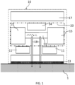
- FIG. 1 shows a schematic block diagram of an example of a sensor (10) for measuring the partial pressure of CO 2 in the skin (1) of a human patient.
- the sensor (10) comprises a housing, a measuring unit (20), a patient interface in the form of a membrane (13) contacting the skin (1) of the patient when in use, and protecting the sensor (10) against e.g. moisture and dust.
- the sensor comprises thermistors (11) for measuring the sensor temperature, used for controlling a heating element (17).
- the temperature readout from the thermistors (11) is further used for signal processing when converting the detector signal into a partial pressure of CO 2 e.g. by the Severinghaus equation.
- the two chimneys (18) connect a measuring chamber (23) with the skin surface through the membrane (13), whereby gases diffusing through the skin are transported through the membrane (13) and the chimneys (18) to the measuring chamber (23).
- the measuring chamber (23) is closed off at one end by a light source (21), and at the opposite end by a detector system in the shape of a dual channel detector (15).
- the skin (1) of the patient, the chimneys (18) and the measuring chamber (23) define a closed system.
- the electronic board (14) comprises amplification, filtering, A/D converter, and signal processing means.
- the electronic board (14) communicates with the dual channel detector (15), to convert the signals received from the dual channel detector (15), into a value representing the partial pressure of blood gases in the skin of the patient.
- the signal processing at the electronic board (14) receives information from at least one of the thermistors (11) regarding the sensor (10) surface temperature to control the heating element (17) that heats the sensor (10).
- the heating element (17) is used to warm up the sensor (10), which again warms up the skin of the human patient.
- the thermistors (11) are also used to control the heating element (17), to achieve the correct applied sensor (10) temperature and avoid burning the skin of the patient.
- the design as described with respect to FIG. 1 has two thermistors (11).
- One thermistor (11) would be enough for the purpose, but it has become a standard within the industry to have two thermistors (11), doubling the sensor (10) temperature control since it is important to measure the correct temperature for calculating the blood gas partial pressure and to avoid burning the skin of the patient.
- the heating of the sensor (10) is programmed by the hospital staff, defining measuring time and temperatures.
- the electronic board (14) also takes care of communication with external equipment (not shown), e.g. a monitor, controller unit connected via electrical cables or smart phones, computers, or tablets connected via wireless means such as WiFi, Bluetooth, GSM or like network.
- the electronic signal processing is performed outside the sensor (10).
- the electronic board (14) is located in a device, e.g. a monitor external to the sensor (10).
- Thermistors (11), heating element (17), light source (21), and the dual channel detector (15) is connected to the electronic board (14) in the external device via electrical cabling e.g. in the form of a bus.
- A/D and D/A conversion are performed in the sensor (10), such that the communication between the sensor (10) and the external device is digital wired or wireless communication.
- the membrane (13) protects the internal parts of the sensor (10), e.g. the electronics, the chimneys (18), and the measuring chamber (23) against intruding particles such as moisture and dust.
- the membrane (13) is permeable to blood gases, hydrophobic, mechanically robust and does not change the permeability or structural behavior when in contact with alcohol swab, contact gel or sweat. It allows the blood gases to diffuse from the patient skin to penetrate the membrane (13), while blocking dust and moisture from penetrating the membrane (13) to potentially harm the sensor (10), measuring parts, electronics, or block the chimneys (18) and thus obstructing the passageway for the blood gases between the skin of the patient and the measuring chamber (23).
- the chimneys (18) have a diameter of 200 ⁇ m and a length of no more than 4 mm.
- the length of the chimneys (18) should preferably be as short as possible, since the volume of gas within the chimneys (18) adds to the total volume of the gas measuring chamber (23), hence the volume here has negative effect on the sensitivity. Some length is however necessary to allow the photodetector and the light source to be positioned at either side of the measuring chamber (23), and allow the thermistors (11) to be fitted on the surface of the sensor as they need to be close to the skin to detect the skin temperature.
- the diameter of the chimneys (18) also adds to the total volume and should be chosen as small as possible to in order to keep the response time of the sensor low.
- the measuring chamber (23) has a total volume (here including the volume of the two chimneys (18)) of no more than 2 ⁇ L, due to the small volume of gas diffusing through the skin per time unit, a large volume would dramatically increase the response time of the sensor (10), which should preferably be no more than one minute.
- the interaction length of the measuring chamber (23), i.e. the length of the measuring chamber (23) wherein the light may interact with the blood gas molecules is in the range of 1.5 mm to 30 mm, see also table I.
- FIG. 2 is a detailed schematic block diagram of the gas measuring unit (20) comprising the light source (21) transmitting light into the measuring chamber (23) via an IR transparent glass window (22) made of e.g. ruby or sapphire, protecting the light source (21) and sealing the measuring chamber (23), and a collimating lens (24) sealing the opposite end of the measuring chamber (23).
- the collimating lens (24) is collecting and rectifying the light such that all light are focused at a prism (27).
- the collecting lens defines the focal point and is chosen such that the prism (27) splits the light equally between two photodetectors (25) and (26).
- the collimating lens (24), The prism (27), and the two photodetectors (25, 26) together make up the dual channel detector (15).
- the geometry between the collimating lens (24), the prism (27) and the photodetectors (25, 26) is such that the majority of the light reaching the collimating lens (24) also reach the sensitive point at each of the photodetectors (25, 26) to optimize the sensitivity.
- the prism (27) is coated with an IR reflective coating, e.g. aluminum, gold, silver, or other suitable material.
- the gas measuring chamber (23) and the prism (27) should have a smooth finishing to ensure a good forward reflection, i.e. ensuring that as much light as possible travels from the light source (21) to the photodetectors (25, 26).
- the roughness should be 1/4 ⁇ to 1/20 ⁇ , at 632.8 nm.
- a smooth surface will provide a better signal-to-noise ratio, as a larger percentage of the light will be transmitted from the source (21) to the photodetectors (25, 26), whereas a rougher surface will give more back reflection, or scattering, and reduce the percentage of light reflected back towards the source.
- the gas measuring chamber (23) may be drilled out of a solid piece of metal or another suitable material. The desired roughness is achieved using suitable tooling and/or polishing. Alternatively, the gas measuring chamber (23) may be molded in plastic and then spray coated to achieve the desired reflectivity and roughness.
- Fig. 3 shows a schematic diagram of an alternative gas sensing unit.
- the only difference from Fig. 2 is that the prism (27) is replaced with a reflective grating (28) instead of the prism (27).
- the reflective grating (28) has the advantage compared with the prism (27) that it does not need to be aligned as accurate as the prism (27). However with a correct alignment, the prism (27) is more effective in distributing the light between the two photodetectors (25, 26).
- Fig. 4a shows the absorption spectra of water and carbon dioxide, in the mid IR spectrum, from 0-10 ⁇ m.
- the spectrum is created using the Hitran database maintained by the Atomic and Molecular Physics Division, Harvard-Smithsonian Center for Astrophysics .
- Many more gases absorption spectra's are available in the database, but under normal circumstances only water vapour, carbon dioxide, and oxygen diffuses through the skin, and oxygen does not absorb light. Hence it is only relevant to look at CO 2 and H 2 O.
- water vapour dominates most of the spectrum, but there are narrow bands where CO 2 dominates and also at least one band, where there is essentially no absorbance at all, both are located around the 4 ⁇ m wavelength.
- Fig. 4b shows a close-up at the spectrum from Fig. 4a around the 4 ⁇ m wavelength, where it is already determined that CO 2 has a band with great absorption, i.e. around 4.26 ⁇ m, and where there is also a free band where essentially no gasses absorb light, i.e. around the 3.9 ⁇ m wavelength.
- This graph may further be used for designing the filters such that they cover a suitable bandwidth and has appropriate steep filter coefficients, such that the photodetector covers exactly the band of interest, e.g. 4.26 ⁇ m ⁇ 90 nm for CO 2 and 3.9 ⁇ m ⁇ 45 nm for O 2 .
- Fig. 5 shows the absorption coefficient/cm -1 on the left vertical axis and the filter transmission in percentage on the right vertical axis versus the wavelength in ⁇ m on the horizontal axis.
- the spikes show the gas absorption for CO 2 and the curved line shows the filter function of the reference channel (left) and the active channel (right).
- the reference channel is chosen in a freeband where no gas molecules absorb light and hence all light emitted at this wavelength will pass through to the detector and due to the rather steep gradient of the filter function, and the limited band pass filter, of the reference channel detector it will not receive light that is likely to be absorbed by gas molecules.
- the filter function of the active filter is chosen such that it covers the absorption spectrum for the gas to be determined. The active channel will hence receive light inversely proportional to the amount of gas in the measuring chamber (23). Referring to Figure 4 , it is further seen that there is also a freeband just above the CO 2 absorption band where a reference channel could be placed.
- FIG. 6 shows a sensor (10) for optically measuring the partial pressure of CO 2 in the skin of a patient.
- the sensor is connected to a monitor device (34) via electrical wires (35).
- the monitor is further connected to the power grid and hospital information infrastructure (not shown).
- the sensor (10) comprises signal processing means, some of the signal processing may still be conducted by the monitor (34).
- Fig. 7A shows the warm up time for a sensor according to the invention, wherein the sensor temperature [°C] is plotted as a function of time [minutes].
- the temperature is set to 43°C and the power supplied to the sensor is limited to 500 mW (normally sensors are limited to 1000 mW supply power). After just 3.8 minutes (3 minutes and 48 seconds) the temperature is stable at 43° C but already after 2.2 minutes (2 minutes and 12 seconds) stable CO 2 levels can be determined.
- Increasing the power limit to 1000 mW will approximately cut the warm-up time to half the time, i.e. under 120 seconds for reaching a stable temperature of 43° C and approximately 60 seconds for reaching a stable CO 2 level.
- Fig. 7B shows the relative CO 2 partial pressure for the warm up time corresponding to Figure 7A for a test gas with 10% CO 2 . It can be seen that the CO 2 level stabilizes at around 2 minutes from start-up where also the sensor temperature stabilizes.
- the graph shows 4 different curves with approximately the same course but reaching different levels of CO 2 .
- the difference in CO 2 level reflects that different light sources have been used giving different sensitivity of the sensor, i.e. the system provides the same stabilization point independent of the light source used. The differences in the levels are handled in the initial calibration process.
- the sensor (10) as described with reference to FIG. 1 and 2 is to be placed at the patient's skin (1) for measuring the partial pressure of blood gases in the skin.
- the membrane (13) is permeable to such gases, whereas moisture, dust etc. is blocked from entering the sensor core.
- the blood gases travel through the two chimneys (18) and into the measuring chamber (23).
- the measuring chamber (23), the chimneys (18) and the skin define a closed system.
- the amount of blood gas molecules in the measuring chamber (23) will thus in time reflect the partial pressure of blood gases in the skin tissue of the patient.
- a light source (21) is located, emitting light into the measuring chamber (23).
- the measuring chamber (23) In the measuring chamber (23) light at 4.26 ⁇ m is absorbed by CO 2 molecules in the measuring chamber (23) which lead to a weakening of the light intensity at this wavelength, whereas light at 3.9 ⁇ m is not absorbed and thus passes through the measuring chamber (23) to be detected by the detector (15).
- the difference between the light detected with the reference channel (3.9 ⁇ m) of the detector and the light detected with the active channel of the detector (4.26 ⁇ m) reflects the amount of gas in the measuring chamber (23) and hence the partial pressure of CO 2 in the skin tissue of the patient - see FIGs. 2 and 3 for active and reference channel.
- the difference is calculated by the signal processing device at the electronic board (14).
- the heating element (17) controls the temperature of the sensor, which in turn controls the temperature of the skin of the patient.
- the skin is warmed to temperatures between 25 and 45° C.
- the temperature is controlled by the feedback system comprising at least one thermistor (11) measuring the sensor surface temperature and feeding back signals to the signal processor at the electronic board (14) controlling the heating element (17).
- the sensor was calibrated (initial calibration) by exposing the sensor to gases 1-9, Table II, with a gas flow in the range of 10-20 mL/min in 10 minutes (comprising stabilizing period for each test gas). The last 30 seconds of data is recorded for each gas to establish a median reading. The median values are used as single point for each concentration for the calibration curve. The sensors are further exposed to the gases 1-9 during 10 minutes, before reading the pCO 2 values. The last 200 seconds are recorded to evaluate the mean value, the minimum and maximum value and the standard deviation.
- the response time of the sensor has been determined according to the class II Special Control Guidance for tcPCO 2 , ASTM F984 and IEC 60601-3-1. The maximum 10-90% response time is recorded as can be seen from Table IV. The response time was measured at 44°C, the temperature correction factor was set to 1 and the metabolic offset was 0 (zero) mm Hg. The in vivo correction is also 0 (zero) mm Hg. The test procedure was repeated three times. The test was conducted on a sensor as described herein with two chimneys (18) covered by a membrane (13). As can be seen from the 6 th column, the acceptance criterion is a response time below 60 seconds. As can be seen the SMD5 component, has a significant longer response time than the rest.
Landscapes
- Health & Medical Sciences (AREA)
- Life Sciences & Earth Sciences (AREA)
- Physics & Mathematics (AREA)
- Engineering & Computer Science (AREA)
- Animal Behavior & Ethology (AREA)
- Veterinary Medicine (AREA)
- Biophysics (AREA)
- Biomedical Technology (AREA)
- Heart & Thoracic Surgery (AREA)
- Medical Informatics (AREA)
- Molecular Biology (AREA)
- Surgery (AREA)
- Pathology (AREA)
- General Health & Medical Sciences (AREA)
- Public Health (AREA)
- Otolaryngology (AREA)
- Spectroscopy & Molecular Physics (AREA)
- Optics & Photonics (AREA)
- Signal Processing (AREA)
- Artificial Intelligence (AREA)
- Computer Vision & Pattern Recognition (AREA)
- Physiology (AREA)
- Psychiatry (AREA)
- Investigating Or Analysing Materials By Optical Means (AREA)
- Measurement Of The Respiration, Hearing Ability, Form, And Blood Characteristics Of Living Organisms (AREA)
Claims (10)
- Sensor (10) für eine nichtinvasive Messung des Partialdrucks von CO2 (pCO2) in der Haut eines Menschen, umfassend;- ein Gehäuse (10),- eine Gasmesskammer (23) zum Messen von Gasen,- mindestens einen Kamin (18) für eine Kommunikation von Gasen, die durch die Haut (1) diffundieren, an die Gasmesskammer (23),- eine Breitband-Leuchtdiode (21), die Licht in die Gasmesskammer (23) durchlässt,- ein Detektorsystem (15), umfassend einen ersten und einen zweiten Photodetektor (25, 26) zum Detektieren von Licht, das von der Breitband-Leuchtdiode (21) durch die Gasmesskammer (23) durchgelassen wird,- wobei der erste Photodetektor (25) Licht bei einer Wellenlänge detektiert, wobei CO2 Licht absorbiert,dadurch gekennzeichnet, dass der zweite Photodetektor (26) als ein Nullreferenzdetektor durch Messen von Licht in einem Freiband, wo keine Gase Licht absorbieren, fungiert und in einer Rückkopplungsschleife durch einen Signalprozessor mit der Breitband-Leuchtdiode (21) verbunden ist, zum automatischen Kalibrieren der Breitband-Leuchtdiode (21) gemäß der Menge an Licht, die an dem zweiten Photodetektor (26) empfangen wird.
- Sensor (10) nach Anspruch 1, wobei das Freiband bei 3,9 µm zentriert ist.
- Sensor (10) nach einem der vorstehenden Ansprüche, wobei die Gasmesskammer (23) eine Innenoberfläche eines reflektierenden Materials wie Gold, Silber oder Aluminium aufweist, die ein reflektierendes Rohr ausbildet.
- Sensor (10) nach einem der vorstehenden Ansprüche, wobei die Rauheit des reflektierenden Rohrs kleiner als 1/4 der Wellenlänge des Lichts, das durch das zu bestimmende Gas absorbiert wird, vorzugsweise weniger als 1/8 der Wellenlänge, ist.
- Sensor (10) nach einem der vorstehenden Ansprüche, ferner aufweisend einen Strahlteiler, wie ein reflektierendes Prisma (27) oder ein reflektierendes Gitter (28), zum Teilen des Lichts von der Sammellinse (24) zwischen den Photodetektoren des Sensors (25, 26).
- Sensor (10) nach einem der vorstehenden Ansprüche, wobei die Messkammer (23) zwei gegenüberliegende Öffnungen aufweist, wobei die erste Öffnung durch die Breitband-Leuchtdiode (21) geschlossen ist und die zweite Öffnung durch das Detektorsystem (15) geschlossen ist, wobei hierdurch eine gerade Linie zwischen der Breitband-Leuchtdiode (21) und dem Detektorsystem (15) bereitgestellt wird.
- Sensor (10) nach Anspruch 6, wobei der mindestens eine Kamin (18) für die Kommunikation von Gasen, die durch die Haut diffundieren, an die Gasmesskammer (23) senkrecht zu der Gasmesskammer (23) ist.
- Sensor (10) nach einem der vorstehenden Ansprüche, wobei der Signalprozessor den Partialdruck von CO2 basierend auf der Differenz zwischen den Signalen, die an dem ersten und dem zweiten Photodetektor empfangen werden, berechnet.
- Sensor (10) nach einem der vorstehenden Ansprüche, wobei das Gesamtvolumen der Gasmesskammer und des mindestens einen Kamins (18) nicht mehr als 2 µL ist.
- Sensor nach einem der vorstehenden Ansprüche, wobei der erste Photodetektor (25) einen Bandpassfilter, der bei 4,26 µm zentriert ist, aufweist.
Applications Claiming Priority (2)
| Application Number | Priority Date | Filing Date | Title |
|---|---|---|---|
| DKPA201500260 | 2015-04-30 | ||
| PCT/EP2016/058561 WO2016173877A1 (en) | 2015-04-30 | 2016-04-18 | Noninvasive optical determination of partial pressure of carbon dioxide |
Publications (2)
| Publication Number | Publication Date |
|---|---|
| EP3288456A1 EP3288456A1 (de) | 2018-03-07 |
| EP3288456B1 true EP3288456B1 (de) | 2023-06-07 |
Family
ID=55755606
Family Applications (1)
| Application Number | Title | Priority Date | Filing Date |
|---|---|---|---|
| EP16716885.5A Active EP3288456B1 (de) | 2015-04-30 | 2016-04-18 | Nichtinvasive optische bestimmung des partialdrucks von kohlendioxid |
Country Status (6)
| Country | Link |
|---|---|
| US (1) | US10939854B2 (de) |
| EP (1) | EP3288456B1 (de) |
| JP (1) | JP6496040B2 (de) |
| CN (2) | CN107529996A (de) |
| DK (1) | DK3288456T3 (de) |
| WO (1) | WO2016173877A1 (de) |
Families Citing this family (9)
| Publication number | Priority date | Publication date | Assignee | Title |
|---|---|---|---|---|
| EP3727152A1 (de) * | 2017-12-22 | 2020-10-28 | Radiometer Basel AG | Vorrichtung zum nachweis von kohlendioxid |
| SE545316C2 (en) | 2019-07-05 | 2023-07-04 | Fourth State Systems Ab | Sampling unit, system and method for transcutaneous blood gas monitoring |
| FI130319B (en) * | 2019-10-10 | 2023-06-19 | Teknologian Tutkimuskeskus Vtt Oy | Method and apparatus for measuring a spectrum of a gaseous sample |
| EP4078147A1 (de) * | 2019-12-20 | 2022-10-26 | SenTec AG | Sensor zur gasdetektion und verfahren zur herstellung |
| CN113288054A (zh) * | 2021-05-20 | 2021-08-24 | 同济大学 | 基于密闭空间二氧化碳浓度变化的人体代谢产热测量装置及方法 |
| CN113567344A (zh) * | 2021-09-05 | 2021-10-29 | 中国电波传播研究所(中国电子科技集团公司第二十二研究所) | 一种光谱原理的气体浓度快速分析仪及其运行方法 |
| IT202200005612A1 (it) | 2022-03-22 | 2023-09-22 | E Novia S P A | Dispositivo indossabile per misurare in modo non invasivo la pressione parziale di co2 transcutanea di una persona e relativo metodo di misurazione |
| CN114983404A (zh) * | 2022-04-21 | 2022-09-02 | 北京秋满实医疗科技有限公司 | 一种利用光学实现经皮氧分压tcpO2和经皮二氧化碳分压tcpCO2的方法 |
| WO2025090597A1 (en) * | 2023-10-23 | 2025-05-01 | Worcester Polytechnic Institute | Charge-to-digital converter for time-domain dual lifetime referencing |
Family Cites Families (9)
| Publication number | Priority date | Publication date | Assignee | Title |
|---|---|---|---|---|
| US4041932A (en) * | 1975-02-06 | 1977-08-16 | Fostick Moshe A | Method for monitoring blood gas tension and pH from outside the body |
| GB0218881D0 (en) * | 2002-08-14 | 2002-09-25 | Qinetiq Ltd | Sensor arrangement and method of sensing |
| EP1969997A1 (de) | 2007-03-12 | 2008-09-17 | Radiometer Basel AG | Sensorensystem |
| CN100590418C (zh) * | 2007-12-29 | 2010-02-17 | 北京航空航天大学 | 一种二氧化碳气体分析仪及其分析方法 |
| EP2169384B1 (de) * | 2008-09-30 | 2013-04-10 | General Electric Company | IR-Gassensor mit einem vereinfachten Strahlenteiler. |
| CN101874736A (zh) * | 2010-07-02 | 2010-11-03 | 天津大学 | 一种主流式二氧化碳浓度测量装置 |
| JP5596480B2 (ja) | 2010-09-28 | 2014-09-24 | 旭化成エレクトロニクス株式会社 | ガス濃度検出方法、ガス濃度センサ |
| GB2497296B (en) * | 2011-12-05 | 2017-07-12 | Gassecure As | Gas sensors |
| WO2015010709A1 (en) * | 2013-07-22 | 2015-01-29 | Sentec Ag | Sensor for detection of gas and method for detection of gas |
-
2016
- 2016-04-18 JP JP2017550835A patent/JP6496040B2/ja active Active
- 2016-04-18 WO PCT/EP2016/058561 patent/WO2016173877A1/en not_active Ceased
- 2016-04-18 US US15/569,977 patent/US10939854B2/en active Active
- 2016-04-18 CN CN201680022737.0A patent/CN107529996A/zh active Pending
- 2016-04-18 DK DK16716885.5T patent/DK3288456T3/da active
- 2016-04-18 CN CN202210676319.0A patent/CN115444411A/zh active Pending
- 2016-04-18 EP EP16716885.5A patent/EP3288456B1/de active Active
Also Published As
| Publication number | Publication date |
|---|---|
| JP6496040B2 (ja) | 2019-04-03 |
| EP3288456A1 (de) | 2018-03-07 |
| JP2018514254A (ja) | 2018-06-07 |
| CN115444411A (zh) | 2022-12-09 |
| US20190133504A1 (en) | 2019-05-09 |
| WO2016173877A1 (en) | 2016-11-03 |
| DK3288456T3 (da) | 2023-06-26 |
| CN107529996A (zh) | 2018-01-02 |
| US10939854B2 (en) | 2021-03-09 |
Similar Documents
| Publication | Publication Date | Title |
|---|---|---|
| US10939854B2 (en) | Noninvasive optical determination of partial pressure of carbon dioxide | |
| CN111629664B (zh) | 用于检测二氧化碳的装置 | |
| US7593108B2 (en) | Method of determining analyte concentration in a sample using infrared transmission data | |
| US20080268486A1 (en) | Dual measurement analyte detection system | |
| WO2016027474A1 (en) | Measurement device and method of measuring a concentration of a component of a gas mixture | |
| CN110177503B (zh) | 用于检测体液中的至少一种分析物的可植入传感器元件及方法 | |
| US20050264815A1 (en) | Sample element with fringing-reduction capabilities | |
| EP1969997A1 (de) | Sensorensystem | |
| US20050036146A1 (en) | Sample element qualification | |
| FR2905762A1 (fr) | Systeme et procede de detection et d'analyse d'au moins une substance volatile dans des echantillons d'haleine d'un sujet | |
| JP2003235832A (ja) | 体液内の分析対象物を測定するための非浸襲的システム | |
| US20150241347A1 (en) | Nondispersive infrared micro-optics sensor for blood alcohol concentration measurements | |
| US20060253097A1 (en) | Methods of treating diabetes | |
| US20050106749A1 (en) | Sample element for use in material analysis | |
| US20050037384A1 (en) | Analyte detection system | |
| TWI603067B (zh) | 光學檢測裝置及方法 | |
| US12016686B2 (en) | Fully implantable sensor element and method for detecting at least one analyte in a body fluid | |
| US20050250217A1 (en) | Vent configuration for sample element | |
| US20090128805A1 (en) | Biological component measuring sensor | |
| US20090195781A1 (en) | Biological information measuring sensor | |
| KR102536484B1 (ko) | 광학적 혈당측정기 구조물 | |
| Fard et al. | Optical glucose monitoring using vertical cavity surface emitting lasers (VCSELs) | |
| Okita et al. | Small-volume cavity cell using hollow optical fiber for Raman scattering-based gas detection | |
| JP2003240709A (ja) | 特定成分の濃度測定方法及びそれに用いる濃度測定用接触子 |
Legal Events
| Date | Code | Title | Description |
|---|---|---|---|
| STAA | Information on the status of an ep patent application or granted ep patent |
Free format text: STATUS: THE INTERNATIONAL PUBLICATION HAS BEEN MADE |
|
| PUAI | Public reference made under article 153(3) epc to a published international application that has entered the european phase |
Free format text: ORIGINAL CODE: 0009012 |
|
| STAA | Information on the status of an ep patent application or granted ep patent |
Free format text: STATUS: REQUEST FOR EXAMINATION WAS MADE |
|
| 17P | Request for examination filed |
Effective date: 20171023 |
|
| AK | Designated contracting states |
Kind code of ref document: A1 Designated state(s): AL AT BE BG CH CY CZ DE DK EE ES FI FR GB GR HR HU IE IS IT LI LT LU LV MC MK MT NL NO PL PT RO RS SE SI SK SM TR |
|
| AX | Request for extension of the european patent |
Extension state: BA ME |
|
| DAV | Request for validation of the european patent (deleted) | ||
| DAX | Request for extension of the european patent (deleted) | ||
| STAA | Information on the status of an ep patent application or granted ep patent |
Free format text: STATUS: EXAMINATION IS IN PROGRESS |
|
| 17Q | First examination report despatched |
Effective date: 20191115 |
|
| GRAP | Despatch of communication of intention to grant a patent |
Free format text: ORIGINAL CODE: EPIDOSNIGR1 |
|
| STAA | Information on the status of an ep patent application or granted ep patent |
Free format text: STATUS: GRANT OF PATENT IS INTENDED |
|
| INTG | Intention to grant announced |
Effective date: 20220404 |
|
| GRAJ | Information related to disapproval of communication of intention to grant by the applicant or resumption of examination proceedings by the epo deleted |
Free format text: ORIGINAL CODE: EPIDOSDIGR1 |
|
| STAA | Information on the status of an ep patent application or granted ep patent |
Free format text: STATUS: EXAMINATION IS IN PROGRESS |
|
| INTC | Intention to grant announced (deleted) | ||
| GRAP | Despatch of communication of intention to grant a patent |
Free format text: ORIGINAL CODE: EPIDOSNIGR1 |
|
| STAA | Information on the status of an ep patent application or granted ep patent |
Free format text: STATUS: GRANT OF PATENT IS INTENDED |
|
| INTG | Intention to grant announced |
Effective date: 20221017 |
|
| GRAS | Grant fee paid |
Free format text: ORIGINAL CODE: EPIDOSNIGR3 |
|
| GRAA | (expected) grant |
Free format text: ORIGINAL CODE: 0009210 |
|
| STAA | Information on the status of an ep patent application or granted ep patent |
Free format text: STATUS: THE PATENT HAS BEEN GRANTED |
|
| AK | Designated contracting states |
Kind code of ref document: B1 Designated state(s): AL AT BE BG CH CY CZ DE DK EE ES FI FR GB GR HR HU IE IS IT LI LT LU LV MC MK MT NL NO PL PT RO RS SE SI SK SM TR |
|
| REG | Reference to a national code |
Ref country code: GB Ref legal event code: FG4D |
|
| REG | Reference to a national code |
Ref country code: CH Ref legal event code: EP Ref country code: AT Ref legal event code: REF Ref document number: 1572355 Country of ref document: AT Kind code of ref document: T Effective date: 20230615 |
|
| REG | Reference to a national code |
Ref country code: DE Ref legal event code: R096 Ref document number: 602016079870 Country of ref document: DE |
|
| REG | Reference to a national code |
Ref country code: DK Ref legal event code: T3 Effective date: 20230619 |
|
| REG | Reference to a national code |
Ref country code: NL Ref legal event code: FP |
|
| P01 | Opt-out of the competence of the unified patent court (upc) registered |
Effective date: 20230530 |
|
| REG | Reference to a national code |
Ref country code: LT Ref legal event code: MG9D |
|
| PG25 | Lapsed in a contracting state [announced via postgrant information from national office to epo] |
Ref country code: SE Free format text: LAPSE BECAUSE OF FAILURE TO SUBMIT A TRANSLATION OF THE DESCRIPTION OR TO PAY THE FEE WITHIN THE PRESCRIBED TIME-LIMIT Effective date: 20230607 Ref country code: NO Free format text: LAPSE BECAUSE OF FAILURE TO SUBMIT A TRANSLATION OF THE DESCRIPTION OR TO PAY THE FEE WITHIN THE PRESCRIBED TIME-LIMIT Effective date: 20230907 Ref country code: ES Free format text: LAPSE BECAUSE OF FAILURE TO SUBMIT A TRANSLATION OF THE DESCRIPTION OR TO PAY THE FEE WITHIN THE PRESCRIBED TIME-LIMIT Effective date: 20230607 |
|
| REG | Reference to a national code |
Ref country code: AT Ref legal event code: MK05 Ref document number: 1572355 Country of ref document: AT Kind code of ref document: T Effective date: 20230607 |
|
| PG25 | Lapsed in a contracting state [announced via postgrant information from national office to epo] |
Ref country code: RS Free format text: LAPSE BECAUSE OF FAILURE TO SUBMIT A TRANSLATION OF THE DESCRIPTION OR TO PAY THE FEE WITHIN THE PRESCRIBED TIME-LIMIT Effective date: 20230607 Ref country code: LV Free format text: LAPSE BECAUSE OF FAILURE TO SUBMIT A TRANSLATION OF THE DESCRIPTION OR TO PAY THE FEE WITHIN THE PRESCRIBED TIME-LIMIT Effective date: 20230607 Ref country code: LT Free format text: LAPSE BECAUSE OF FAILURE TO SUBMIT A TRANSLATION OF THE DESCRIPTION OR TO PAY THE FEE WITHIN THE PRESCRIBED TIME-LIMIT Effective date: 20230607 Ref country code: HR Free format text: LAPSE BECAUSE OF FAILURE TO SUBMIT A TRANSLATION OF THE DESCRIPTION OR TO PAY THE FEE WITHIN THE PRESCRIBED TIME-LIMIT Effective date: 20230607 Ref country code: GR Free format text: LAPSE BECAUSE OF FAILURE TO SUBMIT A TRANSLATION OF THE DESCRIPTION OR TO PAY THE FEE WITHIN THE PRESCRIBED TIME-LIMIT Effective date: 20230908 |
|
| PG25 | Lapsed in a contracting state [announced via postgrant information from national office to epo] |
Ref country code: FI Free format text: LAPSE BECAUSE OF FAILURE TO SUBMIT A TRANSLATION OF THE DESCRIPTION OR TO PAY THE FEE WITHIN THE PRESCRIBED TIME-LIMIT Effective date: 20230607 |
|
| PG25 | Lapsed in a contracting state [announced via postgrant information from national office to epo] |
Ref country code: SK Free format text: LAPSE BECAUSE OF FAILURE TO SUBMIT A TRANSLATION OF THE DESCRIPTION OR TO PAY THE FEE WITHIN THE PRESCRIBED TIME-LIMIT Effective date: 20230607 |
|
| PG25 | Lapsed in a contracting state [announced via postgrant information from national office to epo] |
Ref country code: IS Free format text: LAPSE BECAUSE OF FAILURE TO SUBMIT A TRANSLATION OF THE DESCRIPTION OR TO PAY THE FEE WITHIN THE PRESCRIBED TIME-LIMIT Effective date: 20231007 |
|
| PG25 | Lapsed in a contracting state [announced via postgrant information from national office to epo] |
Ref country code: SM Free format text: LAPSE BECAUSE OF FAILURE TO SUBMIT A TRANSLATION OF THE DESCRIPTION OR TO PAY THE FEE WITHIN THE PRESCRIBED TIME-LIMIT Effective date: 20230607 Ref country code: SK Free format text: LAPSE BECAUSE OF FAILURE TO SUBMIT A TRANSLATION OF THE DESCRIPTION OR TO PAY THE FEE WITHIN THE PRESCRIBED TIME-LIMIT Effective date: 20230607 Ref country code: RO Free format text: LAPSE BECAUSE OF FAILURE TO SUBMIT A TRANSLATION OF THE DESCRIPTION OR TO PAY THE FEE WITHIN THE PRESCRIBED TIME-LIMIT Effective date: 20230607 Ref country code: PT Free format text: LAPSE BECAUSE OF FAILURE TO SUBMIT A TRANSLATION OF THE DESCRIPTION OR TO PAY THE FEE WITHIN THE PRESCRIBED TIME-LIMIT Effective date: 20231009 Ref country code: IS Free format text: LAPSE BECAUSE OF FAILURE TO SUBMIT A TRANSLATION OF THE DESCRIPTION OR TO PAY THE FEE WITHIN THE PRESCRIBED TIME-LIMIT Effective date: 20231007 Ref country code: EE Free format text: LAPSE BECAUSE OF FAILURE TO SUBMIT A TRANSLATION OF THE DESCRIPTION OR TO PAY THE FEE WITHIN THE PRESCRIBED TIME-LIMIT Effective date: 20230607 Ref country code: CZ Free format text: LAPSE BECAUSE OF FAILURE TO SUBMIT A TRANSLATION OF THE DESCRIPTION OR TO PAY THE FEE WITHIN THE PRESCRIBED TIME-LIMIT Effective date: 20230607 Ref country code: AT Free format text: LAPSE BECAUSE OF FAILURE TO SUBMIT A TRANSLATION OF THE DESCRIPTION OR TO PAY THE FEE WITHIN THE PRESCRIBED TIME-LIMIT Effective date: 20230607 |
|
| PG25 | Lapsed in a contracting state [announced via postgrant information from national office to epo] |
Ref country code: PL Free format text: LAPSE BECAUSE OF FAILURE TO SUBMIT A TRANSLATION OF THE DESCRIPTION OR TO PAY THE FEE WITHIN THE PRESCRIBED TIME-LIMIT Effective date: 20230607 |
|
| REG | Reference to a national code |
Ref country code: DE Ref legal event code: R097 Ref document number: 602016079870 Country of ref document: DE |
|
| PLBE | No opposition filed within time limit |
Free format text: ORIGINAL CODE: 0009261 |
|
| STAA | Information on the status of an ep patent application or granted ep patent |
Free format text: STATUS: NO OPPOSITION FILED WITHIN TIME LIMIT |
|
| PG25 | Lapsed in a contracting state [announced via postgrant information from national office to epo] |
Ref country code: SI Free format text: LAPSE BECAUSE OF FAILURE TO SUBMIT A TRANSLATION OF THE DESCRIPTION OR TO PAY THE FEE WITHIN THE PRESCRIBED TIME-LIMIT Effective date: 20230607 |
|
| 26N | No opposition filed |
Effective date: 20240308 |
|
| PG25 | Lapsed in a contracting state [announced via postgrant information from national office to epo] |
Ref country code: SI Free format text: LAPSE BECAUSE OF FAILURE TO SUBMIT A TRANSLATION OF THE DESCRIPTION OR TO PAY THE FEE WITHIN THE PRESCRIBED TIME-LIMIT Effective date: 20230607 Ref country code: IT Free format text: LAPSE BECAUSE OF FAILURE TO SUBMIT A TRANSLATION OF THE DESCRIPTION OR TO PAY THE FEE WITHIN THE PRESCRIBED TIME-LIMIT Effective date: 20230607 |
|
| PG25 | Lapsed in a contracting state [announced via postgrant information from national office to epo] |
Ref country code: BG Free format text: LAPSE BECAUSE OF FAILURE TO SUBMIT A TRANSLATION OF THE DESCRIPTION OR TO PAY THE FEE WITHIN THE PRESCRIBED TIME-LIMIT Effective date: 20230607 |
|
| PG25 | Lapsed in a contracting state [announced via postgrant information from national office to epo] |
Ref country code: MC Free format text: LAPSE BECAUSE OF FAILURE TO SUBMIT A TRANSLATION OF THE DESCRIPTION OR TO PAY THE FEE WITHIN THE PRESCRIBED TIME-LIMIT Effective date: 20230607 |
|
| PG25 | Lapsed in a contracting state [announced via postgrant information from national office to epo] |
Ref country code: MC Free format text: LAPSE BECAUSE OF FAILURE TO SUBMIT A TRANSLATION OF THE DESCRIPTION OR TO PAY THE FEE WITHIN THE PRESCRIBED TIME-LIMIT Effective date: 20230607 Ref country code: BG Free format text: LAPSE BECAUSE OF FAILURE TO SUBMIT A TRANSLATION OF THE DESCRIPTION OR TO PAY THE FEE WITHIN THE PRESCRIBED TIME-LIMIT Effective date: 20230607 |
|
| PG25 | Lapsed in a contracting state [announced via postgrant information from national office to epo] |
Ref country code: LU Free format text: LAPSE BECAUSE OF NON-PAYMENT OF DUE FEES Effective date: 20240418 |
|
| REG | Reference to a national code |
Ref country code: BE Ref legal event code: MM Effective date: 20240430 |
|
| PG25 | Lapsed in a contracting state [announced via postgrant information from national office to epo] |
Ref country code: LU Free format text: LAPSE BECAUSE OF NON-PAYMENT OF DUE FEES Effective date: 20240418 |
|
| PG25 | Lapsed in a contracting state [announced via postgrant information from national office to epo] |
Ref country code: BE Free format text: LAPSE BECAUSE OF NON-PAYMENT OF DUE FEES Effective date: 20240430 |
|
| PG25 | Lapsed in a contracting state [announced via postgrant information from national office to epo] |
Ref country code: BE Free format text: LAPSE BECAUSE OF NON-PAYMENT OF DUE FEES Effective date: 20240430 |
|
| PG25 | Lapsed in a contracting state [announced via postgrant information from national office to epo] |
Ref country code: IE Free format text: LAPSE BECAUSE OF NON-PAYMENT OF DUE FEES Effective date: 20240418 |
|
| PGFP | Annual fee paid to national office [announced via postgrant information from national office to epo] |
Ref country code: NL Payment date: 20250424 Year of fee payment: 10 |
|
| PGFP | Annual fee paid to national office [announced via postgrant information from national office to epo] |
Ref country code: DE Payment date: 20250428 Year of fee payment: 10 |
|
| PGFP | Annual fee paid to national office [announced via postgrant information from national office to epo] |
Ref country code: DK Payment date: 20250424 Year of fee payment: 10 |
|
| PGFP | Annual fee paid to national office [announced via postgrant information from national office to epo] |
Ref country code: FR Payment date: 20250424 Year of fee payment: 10 |
|
| PGFP | Annual fee paid to national office [announced via postgrant information from national office to epo] |
Ref country code: CH Payment date: 20250501 Year of fee payment: 10 |
|
| PG25 | Lapsed in a contracting state [announced via postgrant information from national office to epo] |
Ref country code: CY Free format text: LAPSE BECAUSE OF FAILURE TO SUBMIT A TRANSLATION OF THE DESCRIPTION OR TO PAY THE FEE WITHIN THE PRESCRIBED TIME-LIMIT; INVALID AB INITIO Effective date: 20160418 |
|
| PG25 | Lapsed in a contracting state [announced via postgrant information from national office to epo] |
Ref country code: HU Free format text: LAPSE BECAUSE OF FAILURE TO SUBMIT A TRANSLATION OF THE DESCRIPTION OR TO PAY THE FEE WITHIN THE PRESCRIBED TIME-LIMIT; INVALID AB INITIO Effective date: 20160418 |
|
| PGFP | Annual fee paid to national office [announced via postgrant information from national office to epo] |
Ref country code: GB Payment date: 20260223 Year of fee payment: 11 |
|
| REG | Reference to a national code |
Ref country code: CH Ref legal event code: U11 Free format text: ST27 STATUS EVENT CODE: U-0-0-U10-U11 (AS PROVIDED BY THE NATIONAL OFFICE) Effective date: 20260501 |