EP3288399B1 - Verfahren und vorrichtung zur entfernung eines teils eines lebensmittelprodukts mit einem abrasiven strom - Google Patents
Verfahren und vorrichtung zur entfernung eines teils eines lebensmittelprodukts mit einem abrasiven strom Download PDFInfo
- Publication number
- EP3288399B1 EP3288399B1 EP16786948.6A EP16786948A EP3288399B1 EP 3288399 B1 EP3288399 B1 EP 3288399B1 EP 16786948 A EP16786948 A EP 16786948A EP 3288399 B1 EP3288399 B1 EP 3288399B1
- Authority
- EP
- European Patent Office
- Prior art keywords
- abrasive
- food product
- attrition
- fluid
- stream
- Prior art date
- Legal status (The legal status is an assumption and is not a legal conclusion. Google has not performed a legal analysis and makes no representation as to the accuracy of the status listed.)
- Active
Links
Images






Classifications
-
- A—HUMAN NECESSITIES
- A23—FOODS OR FOODSTUFFS; TREATMENT THEREOF, NOT COVERED BY OTHER CLASSES
- A23N—MACHINES OR APPARATUS FOR TREATING HARVESTED FRUIT, VEGETABLES OR FLOWER BULBS IN BULK, NOT OTHERWISE PROVIDED FOR; PEELING VEGETABLES OR FRUIT IN BULK; APPARATUS FOR PREPARING ANIMAL FEEDING- STUFFS
- A23N7/00—Peeling vegetables or fruit
- A23N7/02—Peeling potatoes, apples or similarly shaped vegetables or fruit
- A23N7/023—Peeling potatoes, apples or similarly shaped vegetables or fruit one by one
-
- A—HUMAN NECESSITIES
- A23—FOODS OR FOODSTUFFS; TREATMENT THEREOF, NOT COVERED BY OTHER CLASSES
- A23L—FOODS, FOODSTUFFS OR NON-ALCOHOLIC BEVERAGES, NOT OTHERWISE PROVIDED FOR; PREPARATION OR TREATMENT THEREOF
- A23L5/00—Preparation or treatment of foods or foodstuffs, in general; Food or foodstuffs obtained thereby; Materials therefor
- A23L5/57—Chemical peeling or cleaning of harvested fruits, vegetables or other foodstuffs
-
- A—HUMAN NECESSITIES
- A23—FOODS OR FOODSTUFFS; TREATMENT THEREOF, NOT COVERED BY OTHER CLASSES
- A23L—FOODS, FOODSTUFFS OR NON-ALCOHOLIC BEVERAGES, NOT OTHERWISE PROVIDED FOR; PREPARATION OR TREATMENT THEREOF
- A23L7/00—Cereal-derived products; Malt products; Preparation or treatment thereof
-
- A—HUMAN NECESSITIES
- A23—FOODS OR FOODSTUFFS; TREATMENT THEREOF, NOT COVERED BY OTHER CLASSES
- A23N—MACHINES OR APPARATUS FOR TREATING HARVESTED FRUIT, VEGETABLES OR FLOWER BULBS IN BULK, NOT OTHERWISE PROVIDED FOR; PEELING VEGETABLES OR FRUIT IN BULK; APPARATUS FOR PREPARING ANIMAL FEEDING- STUFFS
- A23N7/00—Peeling vegetables or fruit
-
- A—HUMAN NECESSITIES
- A23—FOODS OR FOODSTUFFS; TREATMENT THEREOF, NOT COVERED BY OTHER CLASSES
- A23N—MACHINES OR APPARATUS FOR TREATING HARVESTED FRUIT, VEGETABLES OR FLOWER BULBS IN BULK, NOT OTHERWISE PROVIDED FOR; PEELING VEGETABLES OR FRUIT IN BULK; APPARATUS FOR PREPARING ANIMAL FEEDING- STUFFS
- A23N7/00—Peeling vegetables or fruit
- A23N7/02—Peeling potatoes, apples or similarly shaped vegetables or fruit
-
- A—HUMAN NECESSITIES
- A23—FOODS OR FOODSTUFFS; TREATMENT THEREOF, NOT COVERED BY OTHER CLASSES
- A23N—MACHINES OR APPARATUS FOR TREATING HARVESTED FRUIT, VEGETABLES OR FLOWER BULBS IN BULK, NOT OTHERWISE PROVIDED FOR; PEELING VEGETABLES OR FRUIT IN BULK; APPARATUS FOR PREPARING ANIMAL FEEDING- STUFFS
- A23N7/00—Peeling vegetables or fruit
- A23N7/04—Peeling asparagus
-
- A—HUMAN NECESSITIES
- A23—FOODS OR FOODSTUFFS; TREATMENT THEREOF, NOT COVERED BY OTHER CLASSES
- A23N—MACHINES OR APPARATUS FOR TREATING HARVESTED FRUIT, VEGETABLES OR FLOWER BULBS IN BULK, NOT OTHERWISE PROVIDED FOR; PEELING VEGETABLES OR FRUIT IN BULK; APPARATUS FOR PREPARING ANIMAL FEEDING- STUFFS
- A23N7/00—Peeling vegetables or fruit
- A23N7/10—Driving mechanisms
-
- B—PERFORMING OPERATIONS; TRANSPORTING
- B24—GRINDING; POLISHING
- B24C—ABRASIVE OR RELATED BLASTING WITH PARTICULATE MATERIAL
- B24C11/00—Selection of abrasive materials or additives for abrasive blasts
-
- B—PERFORMING OPERATIONS; TRANSPORTING
- B24—GRINDING; POLISHING
- B24C—ABRASIVE OR RELATED BLASTING WITH PARTICULATE MATERIAL
- B24C3/00—Abrasive blasting machines or devices; Plants
-
- B—PERFORMING OPERATIONS; TRANSPORTING
- B24—GRINDING; POLISHING
- B24C—ABRASIVE OR RELATED BLASTING WITH PARTICULATE MATERIAL
- B24C3/00—Abrasive blasting machines or devices; Plants
- B24C3/08—Abrasive blasting machines or devices; Plants essentially adapted for abrasive blasting of travelling stock or travelling workpieces
-
- B—PERFORMING OPERATIONS; TRANSPORTING
- B24—GRINDING; POLISHING
- B24C—ABRASIVE OR RELATED BLASTING WITH PARTICULATE MATERIAL
- B24C3/00—Abrasive blasting machines or devices; Plants
- B24C3/08—Abrasive blasting machines or devices; Plants essentially adapted for abrasive blasting of travelling stock or travelling workpieces
- B24C3/10—Abrasive blasting machines or devices; Plants essentially adapted for abrasive blasting of travelling stock or travelling workpieces for treating external surfaces
-
- B—PERFORMING OPERATIONS; TRANSPORTING
- B24—GRINDING; POLISHING
- B24C—ABRASIVE OR RELATED BLASTING WITH PARTICULATE MATERIAL
- B24C3/00—Abrasive blasting machines or devices; Plants
- B24C3/08—Abrasive blasting machines or devices; Plants essentially adapted for abrasive blasting of travelling stock or travelling workpieces
- B24C3/10—Abrasive blasting machines or devices; Plants essentially adapted for abrasive blasting of travelling stock or travelling workpieces for treating external surfaces
- B24C3/12—Apparatus using nozzles
-
- B—PERFORMING OPERATIONS; TRANSPORTING
- B24—GRINDING; POLISHING
- B24C—ABRASIVE OR RELATED BLASTING WITH PARTICULATE MATERIAL
- B24C3/00—Abrasive blasting machines or devices; Plants
- B24C3/18—Abrasive blasting machines or devices; Plants essentially provided with means for moving workpieces into different working positions
-
- B—PERFORMING OPERATIONS; TRANSPORTING
- B24—GRINDING; POLISHING
- B24C—ABRASIVE OR RELATED BLASTING WITH PARTICULATE MATERIAL
- B24C3/00—Abrasive blasting machines or devices; Plants
- B24C3/32—Abrasive blasting machines or devices; Plants designed for abrasive blasting of particular work, e.g. the internal surfaces of cylinder blocks
-
- B—PERFORMING OPERATIONS; TRANSPORTING
- B24—GRINDING; POLISHING
- B24C—ABRASIVE OR RELATED BLASTING WITH PARTICULATE MATERIAL
- B24C5/00—Devices or accessories for generating abrasive blasts
-
- B—PERFORMING OPERATIONS; TRANSPORTING
- B24—GRINDING; POLISHING
- B24C—ABRASIVE OR RELATED BLASTING WITH PARTICULATE MATERIAL
- B24C7/00—Equipment for feeding abrasive material; Controlling the flowability, constitution, or other physical characteristics of abrasive blasts
-
- B—PERFORMING OPERATIONS; TRANSPORTING
- B24—GRINDING; POLISHING
- B24C—ABRASIVE OR RELATED BLASTING WITH PARTICULATE MATERIAL
- B24C7/00—Equipment for feeding abrasive material; Controlling the flowability, constitution, or other physical characteristics of abrasive blasts
- B24C7/0007—Equipment for feeding abrasive material; Controlling the flowability, constitution, or other physical characteristics of abrasive blasts the abrasive material being fed in a liquid carrier
Definitions
- the present invention relates to using a fluid and abrasives that are entrained within the fluid to cause attrition of the surface of a food product.
- Existing high volume potato peelers lack the ability to precisely control the degree of peeling accomplished. For example, existing continuous peelers use a random motion of potatoes over a bed of knives, abrasive rolls, or abrasive brushes to remove peeling from potatoes. As a result, existing peelers tend to result in under-peeling or conversely in over-peeling.
- US 2626646 A discloses a method for removing a surface layer from firm or rigid edible vegetable material such as potatoes.
- the method comprises the step of forcefully projecting a suspension of a water soluble non-toxic crystalline material in a saturated aqueous solution of the crystalline material against the surface of the vegetable material to wear off the surface layer.
- DE 3107747 A1 discloses a method for removing the skins of tubers, especially potatoes, the skin being blown or blasted off the tubers by means of a stream of gas, especially a stream of air, containing ice particles.
- the invention provides a method for causing attrition to an outer surface of a food product to provide a removed portion of the food product and a remainder of the food product, the method comprising: sensing a position of the food product; bringing an abrasive stream into contact with the outer surface of the food product, thereby separating at least a portion of the outer surface of the food product from the remainder of the food product to provide the removed portion of the food product, wherein the abrasive stream comprises a fluid and an abrasive, and wherein the outer surface comprises a peel; separating the abrasive and the removed portion of the food product from the remainder of the food product; separating the abrasive from the removed portion of the food product to provide a segregated abrasive; and recycling the segregated abrasive to provide a recycle abrasive.
- the step of bringing the abrasive stream into contact with the outer surface of the food product comprises discharging the abrasive stream into contact with the outer surface of the food product, thereby providing a discharge of the abrasive stream.
- the method further comprises the step: (i) positioning the food product into an attrition zone, optionally wherein positioning of the food product in the attrition zone comprises allowing the food product to fall into the attrition zone; or (ii) discharging the abrasive stream when the food product is in a discharge path of the abrasive stream, and optionally stopping the discharge of the abrasive stream when the food product has passed out of the attrition zone; or (iii) introducing the abrasive into the fluid in a nozzle to provide the abrasive stream.
- a rate of kinetic energy imparted to the outer surface of the food product by the abrasive is at least 93 J/s; or (b) a sum of kinetic energy imparted to the outer surface of the food product by the abrasive is at least 2.0 J; or (c) a rate of momentum imparted to the outer surface of the food product by the abrasive is at least 0.80 g ⁇ m/s 2 ; or (d) wherein a sum of momentum imparted to the outer surface of the food product by the abrasive is at least 0.018 g ⁇ m/s; or (e) a mass flow rate of the abrasive in the abrasive stream is controlled separately from a mass flow rate of the fluid in the abrasive stream; or (f) an average linear velocity of the abrasive stream is about 38-115 m/s; or (g) a velocity pressure head of the abrasive stream at
- the abrasive is salt, and optionally, wherein a point on the outer surface of the food product spends at least 11 milliseconds in contact with the abrasive stream; or (II) the abrasive is starch or potato starch; and optionally wherein the abrasive is potato starch and wherein a point on the outer surface of the food product spends at least 1000 milliseconds in contact with the abrasive stream comprising the potato starch.
- the abrasive comprises a hardness at least as large as a hardness of the removed portion of the food product; or (ii) the abrasive comprises a hardness of at least 5 Mohs; or (iii) the abrasive comprises an average particle size of 20-20,000 ⁇ m, with an average sphericity of 0.5-1.0 and an average aspect ratio of 0.5-1.0.
- the fluid comprises air, or water.
- the abrasive is in fluid communication with a nozzle
- the fluid is in fluid communication with the nozzle
- the fluid passes through the nozzle to provide a fluid jet
- the fluid jet creates a force of suction to draw the abrasive into the fluid in the nozzle, thereby providing the abrasive stream.
- At least 70% of the outer surface of the food product is removed to a depth sufficient to remove the peel of the food product.
- the invention provides an apparatus for causing attrition to an outer surface of a food product wherein the outer surface comprises a peel, to provide a removed portion of the food product and a remainder of the food product, the apparatus comprising: a product positioner to position the food product in an attrition zone and a nozzle for discharging an abrasive stream into contact with the food product in the attrition zone, wherein the abrasive stream comprises a fluid and an abrasive entrained in the fluid, characterized in that it further comprises a sensor to determine a position of the food product, wherein the apparatus is configured to stop the discharge of the abrasive stream when the food product has passed out of the attrition zone; a remainder separator for separating the remainder of the food product from the removed portion of the food product; and a byproduct stream separator for further separating at least two components selected from the group consisting of a recycle abrasive, a fine abrasive, a first removed portion of the
- the apparatus further comprises a fluid source in fluid communication with the nozzle; or an abrasive source in fluid communication with the nozzle; or a plurality of nozzles; or a pressurizer; or an attrition chamber; or an abrasive metering valve; or a vacuum source; or an inlet filter for a vacuum source; or a mechanism, optionally a baffle, for changing a velocity of solids entrained in the fluid relative to a velocity of the fluid so that the solids settle out of the fluid; or a post-attrition food product receiver; or a post-attrition abrasive receiver.
- the nozzle further comprises: a fluid jet nozzle to provide a fluid jet; an abrasive conduit to direct the abrasive toward an outlet of the fluid jet nozzle.
- a food product e.g. a potato
- the characteristics of a potato peel can change when processing different varieties of potatoes, or even when processing a single potato variety depending on whether a potato is part of the first harvest of the season or late storage product.
- a peel on one group of potatoes can be thicker or thinner or require more or less effort to remove than the peel on another group of potatoes
- using the same peeler on both groups of potatoes can result in insufficient peeling for one group, but result in over-peeling and the loss of the valuable starch behind the peel for the other group.
- the presence of unremoved peel can result in undesirable flavors or appearance.
- removing starch behind the peel can cause a costly and noticeable increase in production costs when processing large numbers of potatoes.
- existing peelers do not effectively remove peel from a concavity on a food product (e.g., eyes on potatoes). For example, in order to completely remove the peel from a concavity, typical peelers using rotating blades or knives will have to remove the entire outer surface of the food product to the depth of the peel at the bottom of the concavity.
- existing peelers typically peel whatever portion of a potato contacts an abrasive bed while the potato undergoes a random tumbling motion, existing peelers fail to effectively remove isolated deformities or other undesirable features (e.g. bruises) from potatoes without also removing significant amounts of potato starch.
- one embodiment of the invention advantageously uses an abrasive stream to peel a food product.
- the abrasive uses an abrasive that is safe, inexpensive, and/or readily available to peel the food product.
- the abrasive comprises, consists essentially of, or consists of substances that are non-toxic (e.g., gravel, glass, sand, rocks, dirt, minerals, salt, plant matter, and/or starch).
- the abrasive of one embodiment comprises, consists essentially of, or consists of substances that typically accompany a food product from its origin (e.g., sand, rocks, minerals, salt, plant matter, and/or starch).
- substances typically accompany a food product from its origin (e.g., sand, rocks, minerals, salt, plant matter, and/or starch).
- Using such substances can provide one or more additional advantages. For example, in some embodiments, less expensive systems, less complicated systems, and/or existing systems can be used to separate the abrasive from the food product after the abrasive is used to peel the food product.
- the abrasive can comprise, consist essentially of, or consist of substances that are food grade (e.g., minerals, salt, plant matter, and/or starch).
- food grade e.g., minerals, salt, plant matter, and/or starch.
- inedible and/or non-food grade abrasive becomes imbedded in the food product, additional, expensive, or complicated separation steps can be required.
- the abrasive can comprise, consist essentially of, or consist of an ingredient (e.g., a salt or other seasoning) in a recipe comprising the food product.
- an ingredient e.g., a salt or other seasoning
- any excess abrasive can be removed from the surface of the food product by dissolving the salt in a food grade solvent, and the salt can later be recrystallized for reuse as abrasive.
- salt or potato starch both materials are relatively plentiful, inexpensive, and, in some embodiments, have potential to be used as an abrasive several times.
- one embodiment of the invention provides more precise control over the degree of peeling.
- one embodiment enables an operator to change a depth of peeling achieved by a peeler in real time by changing the velocity of the abrasive fluid used to peel a food product.
- the outer surface of a food product can be removed without removing unacceptable amounts of starch.
- one embodiment provides the same or more complete peeling than existing peelers, but with less starch loss.
- one embodiment of the invention can remove peel from a concavity (e.g., potato eye) on a food product (e.g., with an abrasive stream) without requiring the entire outer surface of the food product to be removed to the depth of the concavity.
- a concavity e.g., potato eye
- a food product e.g., with an abrasive stream
- one embodiment of the invention can selectively remove a targeted portion of a food product (e.g., bruise).
- a targeted portion of a food product e.g., bruise
- one embodiment comprises a sensor to determine the position of the targeted portion of the food product and a mobile, robotic nozzle to discharge an abrasive stream into contact with the targeted portion to selectively remove it.
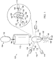
- Figure 1 illustrates an apparatus 100 for causing attrition to an outer surface 102 of a food product 104 to provide a removed portion 106 of the food product 104 and a remainder 108 of the food product 104.
- the attrition is accomplished with an abrasive stream 116 comprising a fluid 118 and an abrasive 120 entrained in the fluid 118.
- the abrasive stream 116 can comprise an abrasive, e.g., salt or potato starch entrained in air.
- an apparatus comprises a product positioner 110 to position the food product 104 in an attrition zone 112.
- product positioners 110 include a stand, a drop tube, a guide, a chute, rails, a conveyor, an auger, augers, and tumblers.
- the embodiment of Figure 1 also comprises an attrition nozzle 114 for discharging an abrasive stream 116 into contact with the food product 104 in the attrition zone 112.
- An example of an attrition zone 112 is a space where an abrasive stream 116 discharged from an attrition nozzle 114 can cause attrition to the outer surface 102 of the food product 104.
- the attrition zone 112 is a volume of space within the path of the abrasive stream 116.
- the attrition zone 112 is a volume of space encompassing all the possible paths of the abrasive stream 116 given the range of motion of the robotic attrition nozzle 114 and the possible velocities of the abrasive stream 116.
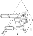
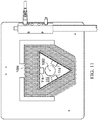
- each attrition nozzle 114 comprises a plurality of attrition nozzles 114 positioned and oriented to direct a plurality of abrasive streams 116 at a target point 1002 (depicted, for example, in Figures 10 , 11 , and 13 ). As illustrated, each attrition nozzle 114 is positioned and oriented to direct the abrasive stream 116 into contact with the food product 104.
- an attrition nozzle 114 or plurality of attrition nozzles 114 can also comprise a valve 328 for controlling the velocity of a fluid 118 and thereby the velocity of the abrasive stream 116 at an outlet 140 of the attrition nozzle 114.
- a plurality of attrition nozzles 114 can be arranged in a ring and evenly spaced from each other.
- one embodiment comprises at least 3, 4, 5, 6, or even more attrition nozzles 114 depending on the surface area of the food product 104 over which attrition is desired.
- the attrition nozzles 114 can be arranged to form an equilateral triangle (e.g., with each attrition nozzle 114 at the vertex of the triangle or with each attrition nozzle 114 at the centerpoint of a side of the equilateral triangle). Nonetheless, in some embodiments, the attrition nozzles 114 are spaced unevenly. For example, differences in position and orientation of the attrition nozzles 114 can be addressed, as applicable, by aiming each attrition nozzle 114 (and therefore each abrasive stream 116) at the food product 104 and/or increasing or decreasing the velocity of an abrasive stream 116 as it exits an attrition nozzle 114.
- the attrition nozzles 114 all provide their respective abrasive streams 116 with a velocity (e.g., magnitude and direction) that acts to provide balanced velocity head on the food product 104.
- a velocity e.g., magnitude and direction
- the abrasive streams 116 in combination, result in substantially no net force or torque on the food product 104.
- any net torque or force on the food product 104 as a result of the abrasive streams 116 moves the food product 104 into a desired position and/or orientation or any net torque is not large enough to substantially move the position and/or orientation of the food product 104 away from a desired position and orientation.
- a desired position can be a position that is substantially centered in an attrition zone 112 between the attrition nozzles 114, and a desired orientation can be an orientation with a long dimension of the food product 104 oriented substantially parallel to the direction of movement 146 of the food product 104 through the attrition zone 112 or oriented substantially parallel to a central axis of the attrition zone 112.
- an attrition nozzle 114 can be positioned and oriented to provide an incident angle 122 between an average direction 124 of the abrasive stream 116 and the line 126 normal to the outer surface 102 of the food product 104.
- Figure 1 illustrates a point 128 of intersection where the average direction 124 of the abrasive stream 116 intersects the outer surface 102 of the food product 104.
- Figure 1 also illustrates a line 126 normal to the outer surface 102 of the food product 104 at the point 128 of intersection.
- the incident angle 122 is the angle between the average direction 124 of the abrasive stream 116 and the line 126 normal to the outer surface 102 of the food product 104.
- one embodiment of the invention comprises a fluid jet nozzle 1302, an abrasive conduit 1306, and an abrasive stream discharge nozzle 1310.
- an attrition nozzle 114 for the abrasive stream 116 comprises a fluid jet nozzle 1302 for providing a fluid jet 1304 inside the attrition nozzle 114.
- the abrasive conduit 1306 directs the abrasive 120 toward an outlet 1308 of the fluid jet nozzle 1302.
- An abrasive stream 116 is formed when the fluid jet 1304 draws the abrasive 120 through the abrasive conduit 1306 and into the fluid jet 1304. Then, the abrasive stream 116 is discharged through the abrasive stream discharge nozzle 1310.
- the embodiment comprises a path 324 of fluid communication for the fluid 118 between a fluid source 304 for the fluid and the fluid jet nozzle 1302.
- the embodiment comprises a path 326 of fluid communication for the abrasive 120 between an abrasive source 306 for the abrasive 120 and the abrasive conduit 1306.
- an apparatus comprises a remainder separator 302 for substantially separating the remainder 108 of the food product 104 from the removed portion 106 of the food product 104.
- the remainder separator 302 comprises a size based solid-solid separator, for example, an opening (e.g., a slot) or plurality of openings (e.g., a screen).
- the opening is large enough that the abrasive 120 and removed portion 106 of the food product 104 can pass through the opening.
- the opening is also small enough that the remainder 108 of the food product 104 cannot pass through the opening.
- the remainder separator 302 can be used to simultaneously separate the remainder 108 of the food product 104 from both the abrasive 120 and the removed portion 106 of the food product 104. In some embodiments, at least 50%, at least 70%, at least 80%, or at least 90% of the removed portion 106 of the food product 104 and the abrasive 120 used to remove the removed portion are separated from the remainder 108 of the food product.
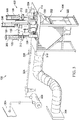
- one embodiment of the invention comprises a fluid source 304 in fluid communication with the attrition nozzle 114.
- a fluid source 304 include a tank, a vessel, the atmosphere, a supply line, a utility line, etc.
- the embodiment of Figure 3 also comprises a pressurizer 308, for example, a pump or a compressor to provide pressurized fluid 118.
- some embodiments comprise a vessel that is pressurized to provide pressurized fluid 118.
- the illustrated embodiment of Figure 3 also comprises an abrasive source 306 in fluid communication with the attrition nozzle 114.
- an abrasive source 306 include a hopper, a tank, a vessel, a supply line, etc.
- the embodiment comprises an abrasive source 306 for each of a plurality of attrition nozzles 114.
- using a plurality of abrasive sources 306 can help to reduce the risk of the abrasive 120 clogging.
- using a plurality of abrasive sources 306 can help to minimize the distance between the outlet of an abrasive source 306 and the outlet 140 of an attrition nozzle 114 for the abrasive stream 116.
- This in turn, can help minimize the distance over which the pressure of the abrasive 120 decreases from a higher value (e.g., atmospheric pressure plus static pressure) to a lower pressure (e.g., vacuum pressure caused by the fluid jet 1304 at the outlet of the abrasive conduit 1306), thereby increasing the velocity of the abrasive 120 over the distance and decreasing the risk of the abrasive 120 clogging.
- a higher value e.g., atmospheric pressure plus static pressure
- a lower pressure e.g., vacuum pressure caused by the fluid jet 1304 at the outlet of the abrasive conduit 1306
- Using a plurality of abrasive sources 306 can also help to more precisely and accurately control the amount of abrasive 120 in each of a plurality of abrasive streams 116 discharged by a plurality of attrition nozzles 114.
- one and only one abrasive source 306 with a splitter can be used, but if the system for providing the abrasive streams 116 to the attrition zone 112 has any asymmetries, the abrasive 120 can be distributed unevenly unless additional controls are put in place. Accordingly, it can be more desirable to separately meter the abrasive 120 flowing to each abrasive stream 116.
- an abrasive metering valve 312 can be used to control a mass flow rate of the abrasive 120 to each of a plurality of attrition nozzles 114.
- a mass flow rate of a substance e.g., the abrasive 120
- the abrasive metering valve 312 controls the amount of abrasive 120 fed to or mixed with the fluid 118 to form the abrasive stream 116.
- An example of an abrasive metering valve 312 is the BLASTMASTER® REGULATOR JR. abrasive metering valve 312 available from Marco, 701 East Boulevard, Deer Park, Texas 77536, US.
- one embodiment of the invention comprises an attrition chamber 310.
- the attrition chamber 310 protects the food product 104 from contamination.
- the attrition chamber 310 protects operators or nearby items from exposure to the abrasive stream 116.
- the embodiment in Figure 3 also comprises a vacuum source 314.
- the vacuum source 314 can be a blower.
- the blower draws the fluid 118 (e.g., air) from the attrition chamber 310 through a filter 316 to provide a vacuum.
- the vacuum source 314 provides a vacuum throughout the entire system (e.g., from the attrition chamber 310 to the inlet of the blower).
- the outlet of the blower is at atmospheric pressure
- the inlet of the blower is at a pressure lower than atmospheric pressure
- the inlet to the pressure system in fluid communication with the inlet of the blower e.g., inlet to the attrition chamber 310, product positioner 110, or some other upstream component
- the pressure is below atmospheric pressure or under vacuum.
- Using vacuum source 314 can be helpful to provide a vacuum in the product attrition chamber 310, a container assembly, or any other component of an embodiment downstream of the attrition chamber 310 and likely to be exposed to attrition byproducts 256 from the attrition chamber 310 (e.g., the removed portion 106 of the food product 104 or the abrasive 120).
- providing a vacuum can be useful so solids (e.g., abrasive 120, and removed portion 106 of the food product 104) in the container assembly tend to remain within the container assembly, rather than escaping to the local environment, which is at a higher pressure (e.g., atmospheric pressure). This can help protect operators from inhaling solids, and thereby create a safer working environment.
- one embodiment of the invention comprises a filter 316 (e.g., an inlet filter for the vacuum source 314).
- the filter 316 can remove solids from the fluid 118 leaving the attrition chamber 310 and can remove solids before they reach the vacuum source 314.
- the filter 316 is placed as close to the attrition chamber 310 as possible to minimize the opportunity for entrained solids to escape into the environment.
- one embodiment of the invention comprises a settling device (e.g., a baffle 318) to cause a change in the velocity (e.g., speed and/or magnitude) of the fluid 118 and thereby cause entrained solids (e.g., abrasive 120 and/or the removed portion 106 of the food product 104) to settle out of the fluid 118.
- a filter 316 is positioned after and proximate a settling device 318. The illustrated arrangement can be useful to reduce the load on the filter 316.
- a settling device can be used without a filter 316 or a filter can be used without a settling device.
- the settling device or baffle 318 is replaced with or is a mechanism for changing (e.g., decreasing) a velocity of solids entrained in the fluid relative to a velocity of the fluid so that the solids settle out of the fluid.
- the mechanism can be a hydrocyclone or other density-based separation device, and the solids entrained in the fluid can be the abrasive and/or the removed portion of the food product.
- the solids after the solids pass by or through the mechanism, the solids are no longer entrained in the fluid.
- the direction and/or magnitude of the resultant force vector on the solids is different than the direction and/or magnitude of the resultant force vector on the fluid, thereby causing the solids to drop out of suspension in the fluid.
- the abrasive stream 116 (and any additional entrained solids, e.g., attrition byproducts 256 such as the removed portion of food product 104) is directed downward using the baffle 318.
- a post-attrition abrasive receiver 322 e.g., a container or passive or active conveyor for the post-attrition abrasive 120 and other solids entrained in the fluid 118 that exits the attrition zone 112).
- abrasive 120 and other entrained solids can settle out of the fluid 118 and into the post-attrition abrasive receiver 322.
- any entrained solids remaining in the fluid 118 can be drawn (e.g., upward) into a filter 316 at the inlet to the vacuum source 314 (e.g., a blower which can push the air back to the ambient environment).
- the vacuum source 314 e.g., a blower which can push the air back to the ambient environment.
- the post-attrition abrasive receiver 322 comprises a container (e.g., a drawer, as illustrated, a basin, or a trough)
- the entrained solids that settle out of the fluid 118 can accumulate in the abrasive 120 receiver.
- the abrasive 120 receiver is a conveyor (e.g., passive conveyor such as chute, or active conveyor, such as augers, an endless conveyor belt, etc.), the abrasive 120 and other entrained solids that settle out of the fluid 118 can be continuously conveyed to another location for further processing.
- a conveyor e.g., passive conveyor such as chute, or active conveyor, such as augers, an endless conveyor belt, etc.
- one embodiment of the invention comprises a post-attrition food product receiver 320.
- the post-attrition food product receiver 320 can be a container or a passive or active conveyor, and the remainder 108 of the food product 104 can be continuously conveyed to another location for further processing.
- the post-attrition food product receiver 320 is a drawer.
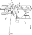
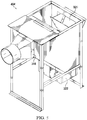
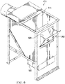
- some embodiments comprise a nozzle assembly 402 which can be separated from a container assembly 404.
- the nozzle assembly 402 comprises nozzles 114, a drop tube 110, an attrition chamber 310, and/or other components.
- the container assembly 404 comprises a product receiver 320, a post-abrasive attrition receiver 322, a baffle 318, and/or other components.
- some embodiments comprise an air intake screen 1004.
- the nozzle assembly 402 comprises the air intake screen 1004.
- an air intake screen 1004 or similar openings are avoided to prevent the loss of vacuum provided by a vacuum source 314.
- the attrition chamber 310 or container assembly 404 and any other components in fluid communication with the vacuum source 314 are sealed against the environment to some extent (e.g., excluding an inlet for the food product, such as a drop tube 110). In some embodiments, this is done to prevent loss of vacuum and to prevent solid particles within the system from escaping to the local environment.
- Figure 14 illustrates a product positioner 110 that comprises a chute, a conveyor, or tumbler (e.g., using augers).
- the product positioner 110 actively or passively conveys the food product 104 to gives the food product a tumbling (e.g., random tumbling) motion.
- at least one sensor 1404 detects the presence and position of a targeted outer surface feature 1402 of the food product.
- at least one nozzle 114 is positioned and oriented to discharge an abrasive stream 116 into contact with the targeted outer surface feature 1402 and thereby separate all or at least a portion of the targeted outer surface feature 1402 from the food product 104.
- one embodiment of the invention comprises a product stream separator 202 for further separating the remainder 108 of the food product 104 from the removed portion 106 of the food product 104 and the abrasive 120.
- the product stream separator 202 can employ solvent-, kinetic-, size- and/or or density-based separation techniques. Examples include subjecting the food product 104 to a water wash, blowing with compressed air, vibration, and/or centrifugal acceleration, etc. Examples of a density separator include a hydrocyclone and a centrifugal separator.
- an apparatus comprises a byproduct stream separator 204 for further separating at least two components selected from the group consisting of recycle abrasive 250, fine abrasive 252, a first removed portion 130 of the food product 104, and a second removed portion 132 of the food product 104.
- the byproduct stream separator 204 comprises solvent-, kinetic-, size- and/or or density-based separator.
- some embodiments of the invention comprise an abrasive-removed-portion separator 206 for substantially separating the removed portion 106 of the food product 104 from the abrasive 120 to provide a segregated abrasive 120a.
- abrasive-removed-portion separator 206 for substantially separating the removed portion 106 of the food product 104 from the abrasive 120 to provide a segregated abrasive 120a.
- at least 50%, at least 70%, at least 80%, or at least 90% of the removed portion 106 present (e.g., mixed, or combined) with the abrasive 120 is separated from the abrasive.
- some embodiments of the invention comprise a secondary removed portion separator 208 for substantially separating a desired portion of the removed portion from another part of the removed portion.
- At least 50%, at least 70%, at least 80%, or at least 90% of the other part of the removed portion 106 is separated from the desired portion of the removed portion.
- An example of a desired portion is the second removed portion 132 (e.g., starch) illustrated in Figures 1 and 2 .
- An example of another part of the removed portion is the first removed portion 130 (e.g., peel) as illustrated in Figures 1 and 2 .
- Figure 2 depicts a block flow diagram illustrating a method for causing attrition to an outer surface 102 of a food product 104 to provide a removed portion 106 of the food product 104 and a remainder 108 of the food product 104.
- an abrasive-fluid mixer 212 (e.g., an attrition nozzle 114) is fed a fluid 118 and a feed stream 254 of the abrasive 120. Additionally, in the illustrated embodiment, the abrasive-fluid mixer 212 provides an abrasive stream 116.
- the abrasive stream 116 is fed to the attrition zone 112 along with a food product 104, and the attrition zone 112 produces a remainder 108 of the food product 104 and an attrition byproduct (e.g., a removed portion 106 of the food product 104 and the abrasive 120).
- an attrition byproduct e.g., a removed portion 106 of the food product 104 and the abrasive 120.
- the remainder 108 of the food product 104 and some of the attrition byproduct 256 is fed to a product stream separator 202.
- the product stream separator 202 is also fed a wash fluid 264 (e.g., gas, liquid, air, water).
- the product stream separator 202 provides a remainder 108 of the food product 104 separated from the attrition byproduct 256.
- the product stream separator 202 also separates the wash fluid 264 from the remainder 108 of the food product 104 and the attrition byproduct 256.
- the product stream separator 202 comprises a secondary product separator 216 and a tertiary processor 218.
- the secondary product separator 216 and/or tertiary processor 218 comprises a solvent-, kinetic-, size- and/or or density-based separator.
- the secondary product separator 216 is fed the remainder 108 of the food product 104 and the attrition byproduct 256, and the secondary product separator 216 separates the remainder 108 of the food product 104 from secondary product separation byproducts 266 (e.g. attrition byproduct 256 and/or wash fluid 264).
- the tertiary processor 218 is fed the secondary product separation byproducts 266 and separates the attrition byproduct 256 from the wash fluid 264.
- the attrition byproduct 256 is further separated, for example, similarly to the attrition byproduct 256 that is fed to an abrasive-removed-portion separator 206 in Figure 2 .
- the attrition byproduct 256 from the tertiary processor 218 can also be fed to the abrasive-removed-portion separator 206.
- a byproduct stream separator 204 is fed attrition byproduct 256 from the attrition zone 112 and separates the attrition byproduct to provide a first removed portion 130 (e.g., peel), a second removed portion 132 (e.g., starch), fine abrasive 252, and/or recycle abrasive 250.
- the byproduct stream separator 204 comprises a solvent-, kinetic-, size- and/or or density-based separator.
- the byproduct stream separator 204 comprises a density-based separator (e.g., a hydrocyclone or centrifugal separator).
- the byproduct stream separator 204 comprises an abrasive-removed-portion separator 206, a secondary removed portion separator 208, and/or a secondary abrasive separator 214.
- the abrasive-removed-portion separator 206, the secondary removed portion separator 208, and/or secondary abrasive separator 214 comprise a solvent-, kinetic-, size- and/or or density-based separator.
- the abrasive-removed-portion separator 206 is fed attrition byproduct 256 from the attrition zone 112 and separates the removed portion 106 of the food product 104 from the abrasive 120 to provide a segregated abrasive 120a.
- the segregated abrasive 120a comprises recycle abrasive 250 and fine abrasive 252.
- An example of recycle abrasive 250 is abrasive 120 that is at least as large as a desired size threshold (e.g., average particle size of 50-2000 ⁇ m) for reuse in the abrasive stream 116.
- a desired size threshold e.g., average particle size of 50-2000 ⁇ m
- smaller particles can also be used, such particles (e.g., with smaller masses) can require prohibitively high velocities to provide a desired amount of momentum and/or kinetic energy for removing the outer surface 102 of a food product 104.
- An example of fine abrasive is abrasive 120 that is smaller than the desired size threshold for reuse in the abrasive stream 116). As illustrated the segregated abrasive 120a is fed to a secondary abrasive separator 214 to separate the recycle abrasive 250 from the fine abrasive 252.
- the recycle abrasive 250 and makeup abrasive 258 are fed to an abrasive mixer 210 to provide a feed stream 254 of abrasive 120, which is in turn fed to the abrasive-fluid mixer 212, along with fluid 118, to provide an abrasive stream 116.
- the fine abrasive 252 is further processed (e.g., by dissolving, recrystallization, and/or drying) to provide recycle abrasive 250.
- the removed portion 106 of the food product 104 comprises a first removed portion 130 (e.g., peel) and a second removed portion 132 (e.g., starch). Furthermore, in some embodiments, the removed portion 106 of the food product 104 from the abrasive-removed-portion separator 206 is fed to a secondary removed portion separator 208 to separate the second removed portion 132 (e.g., starch) from the first removed portion 130 (e.g., peel). In some embodiments, if the second removed portion 132 is being used as an abrasive 120, the second removed portion 132 can be recycle abrasive 250 or can be processed to provide recycle abrasive 250.
- Figure 15 depicts a flow chart for a method for causing attrition to an outer surface 102 of a food product 104 to provide a removed portion 106 of the food product 104 and a remainder 108 of the food product 104. As illustrated, the method comprises several steps.
- an abrasive 120 and a fluid 118 are provided to an attrition nozzle 114 for discharging an abrasive stream 116 comprising the abrasive 120 and the fluid 118.
- the feed stream 254 of the abrasive 120 comprises makeup abrasive 258 and/or recycle abrasive 250.
- the abrasive 120 comprises a hardness at least as large as a hardness of the outer surface 102 of the food product 104.
- the abrasive 120 comprises a hardness at least as large as a hardness of the removed portion 106 of the food product 104.
- the abrasive 120 comprises a hardness of at least about 5 Mohs. In one embodiment, it is desirable to use a harder solid for the abrasive 120 because a collision involving a harder solid tends to more closely resemble an inelastic collision and transfer more kinetic energy to the food product 104 on contact. In one embodiment, it is desirable to use a harder solid for the abrasive 120 because a collision involving a harder solid tends to more closely resemble an inelastic collision (i.e., a collision in which kinetic energy is conserved) and transfer more kinetic energy to the food product 104 on contact with an abrasive 120 possessing a given mass and momentum. Furthermore, a greater rate of transfer of kinetic energy can be desirable, for example, to remove more of an outer surface 102 of the food product 104 after contact with the abrasive 120.
- the abrasive 120 it is desirable for the abrasive 120 to have a higher roughness (e.g., root mean square roughness), to have a sphericity that is less than 1 or an aspect ratio that is not equal to one. These attributes can be desirable as they tend to result in greater removal of the outer surface 102 of the food product 104 if other factors impacting removal remain constant.
- one embodiment comprises an average sphericity of 0.5 - 1.0, less than 0.9, less than 0.8, less than 0.7, or less than 0.6.
- one embodiment comprises abrasive with an average aspect ratio of 0.5 - 1.0. An illustration is useful to understand the aspect ratio.
- a particle has a constant density and an average cross-sectional area.
- the cross-sectional area has an area-weighted centerpoint co-located with the center of mass of the cross-sectional area.
- a plurality of lines with end points on the perimeter of the cross-sectional area can be drawn through the center point.
- An example of the average aspect ratio as used herein is the shortest line in the plurality of lines divided by the longest line in the plurality of lines.
- the abrasive has an average particle size of at least 20 ⁇ m. In one embodiment, the abrasive has an average particle size of 20-20,000 ⁇ m.
- particle size for a particle refers to the diameter of a sphere having the same surface area as the particle. It can be desirable for a particle to have at least a minimum particle size. For example, given a particle density, the mass of the particle is related to the particle size. Furthermore, to provide a desired kinetic energy and/or momentum, a particle with a smaller mass must be moving faster, and accelerating a particle to very high rates of speed can be impractical. On the other hand, a particle with more mass can provide a desired kinetic energy and/or momentum while traveling at a slower speed.
- the abrasive 120 comprises or consists of an inexpensive, readily available solid material.
- the abrasive 120 comprises or is salt (e.g., NaCl) and/or starch (e.g., vegetable starch, tuber starch, potato starch).
- the fluid 118 comprises or is an inexpensive, readily available liquid or gas. In one embodiment the fluid 118 comprises, consists essentially of, or is air and/or water.
- a mass or volumetric flow rate of the abrasive 120 in the abrasive stream 116 is to some extent controlled separately from a mass or volumetric flow rate of the fluid 118 in the abrasive stream 116. For example, this can be useful to ensure that the abrasive 120 is entrained in the fluid 118 in the abrasive stream.
- fluid or abrasive particle characteristics e.g., density, size, viscosity, etc.
- a ratio of the linear velocity of the abrasive 120 to the fluid 118 is controlled, for example, so that the abrasive 120 remains entrained in the fluid 118 in the abrasive stream 116.
- a linear velocity of the abrasive 120 and/or the fluid 118 is controlled, for example, so that the rate at which the abrasive stream 116 transfers momentum and/or kinetic energy to the food product 104 is sufficient to separate the removed portion 106 of the food product 104 from a remainder 108 of the food product 104.
- the abrasive stream 116 remains in contact with the food product 104 for a controlled amount of time.
- the controlled amount of time can be an amount of time sufficient to transfer total amounts of momentum and/or kinetic energy to the food product 104 to separate a desired amount of the removed portion 106 of the food product 104 from a remainder 108 of the food product 104.
- the linear velocity of the abrasive 120 and the fluid 118 can be controlled to provide the abrasive stream 116 with a desired velocity pressure head at an outlet 140 of an attrition nozzle 114 for discharging the abrasive stream 116.
- a food product 104 is positioned in an attrition zone 112.
- the attrition zone 112 comprises or consists of a discharge path 120 of the abrasive stream 116 from an attrition nozzle 114 (e.g., stationary attrition nozzle 114).
- the attrition zone 112 comprises or consists of a space within the discharge scope of a mobile (e.g., robotic) attrition nozzle 114 that is capable of changing a position of the attrition nozzle 114, an orientation of the attrition nozzle 114, and/or a velocity (e.g., speed and direction) of the abrasive stream 116.
- the positioning the food product 104 in the attrition zone 112 comprises allowing the food product 104 to fall into the attrition zone 112, or placing, dropping, or conveying the food product 104 into the attrition zone 112.
- the food product 104 could be placed by a robotic arm, fall or be dropped through a drop tube, or be conveyed by an endless conveyor belt, auger, or tumbler.
- the food product 104 is dropped and/or falls from a minimum elevation above the attrition zone 112 so the velocity of the food product 104 through the attrition zone 112 is minimized and the time that the food product 104 spends in the attrition zone 112 is maximized.
- the food product 104 is dropped from a minimum elevation above the attrition zone 112 to provide the food product 104 with a sufficient velocity to pass through an abrasive stream 116 or a plurality of abrasive streams 116.
- the food product 104 can lack sufficient velocity to pass through the at least one abrasive stream 116 and thus be suspended by the at least one abrasive stream 116.
- this issue can be addressed by using an incident angle 122 of the abrasive stream 116 to accelerate or decelerate the food product 104.
- An example of an incident angle 122 is the angle between the direction of the abrasive stream 116 and a line 126 normal (e.g., perpendicular) to the outer surface of the food product 104 at the point 128 of intersection where the abrasive stream 116 will intersect the surface of the food product 104.
- the abrasive stream 116 is provided at an incident angle 122 to the outer surface 102 of the food product 104 to accelerate the food product 104.
- at least one attrition nozzle 114 for the at least one abrasive stream 116 can be angled in a direction of movement 144 of the food product 104 as the food product 104 approaches the attrition zone 112.
- the at least one attrition nozzle 114 can be directed slightly downward (e.g., 0-20 or 0-10 degrees away from horizontal).
- the abrasive stream 116 is provided at an incident angle 122 to the outer surface 102 of the food product 104 to decelerate the food product 104.
- at least one attrition nozzle 114 for the at least one abrasive stream 116 can be angled opposite a direction of movement 144 of the food product 104 as the food product 104 approaches the attrition zone 112.
- the at least one attrition nozzle 114 can be directed slightly upward (e.g., 0-20 or 0-10 degrees away from horizontal).
- a sufficient rate of kinetic energy and/or a sufficient sum of kinetic energy is imparted to the outer surface 102 of the food product 104 by the abrasive 120 to separate at least a portion (e.g., a first removed portion 130) of the outer surface 102 of the food product 104 from the remainder 108 of the food product 104 to provide the removed potion of the food product 104.
- An example of a rate of kinetic energy imparted is an amount of kinetic energy imparted per time period.
- An example of a sum of kinetic energy imparted is a rate of kinetic energy imparted multiplied by the duration of time that the rate is imparted.
- a rate of momentum imparted is an amount of momentum imparted per time period.
- An example of a sum of momentum imparted is a rate of momentum imparted multiplied by the duration of time that the rate is imparted.
- At least a portion (e.g., a first removed portion 130) of the outer surface 102 of the food product 104 at a point on the outer surface 102 of the food product 104 spends sufficient time in contact with the abrasive stream 116 to be separated from the remainder 108 of the food product 104 to provide the removed portion of the food product 104.
- the amount of time that the food product 104 spends in contact with the abrasive 120 can be controlled by controlling the velocity of the food product 104 as it passes through the attrition zone 112.
- the velocity of the food product 104 can be controlled, for example, by the elevation of the food product 104 above the attrition zone 112 when it is dropped, or the velocity with which the food product 104 is conveyed through the attrition zone 112.
- the velocity of the food product 104 through the attrition zone 112 can also be controlled by the velocity (speed and direction) of at least one abrasive stream 116 in the attrition zone 112.
- the amount of time that the food product 104 spends in contact with the abrasive 120 can also be controlled by increasing or decreasing the time for which an abrasive stream 116 is discharged while the food product 104 is in the attrition zone 112.
- the time a food product 104 spends in the attrition zone can be controlled by increasing (or decreasing) the diameter of the nozzle or increasing (or decreasing) the attrition nozzle-to-product distance 138 to create a larger (or smaller) cross-sectional area for the abrasive stream 116. For example, given a food product 104 moving through the attrition zone 112 at a constant speed, if the cross-sectional area of the abrasive stream 116 is increased, the food product will spend more time in the attrition zone and in contact with the abrasive stream.
- a relative position of the food product 104 to a target point 1002 can be determined.
- the relative position of a food product 104 to at least one attrition nozzle 114 can be determined.
- feed forward control can be used to change the velocity (e.g., direction and speed) of at least one abrasive stream 116 at the respective outlet of the at least one attrition nozzle 114.
- at least one attrition nozzle 114 can be repositioned and/or reoriented.
- the pressure drop experienced by the fluid 118 and/or abrasive stream 116 before exiting the attrition nozzle 114 can be increased or decreased (e.g., by opening or closing a valve).
- an air ring can be used to both sense position of food product 104 and position it.
- sensing the position of the food product 104 is used to determine when the food product 104 will reach an attrition zone 112.
- the abrasive stream 116 is discharged (e.g., from an attrition nozzle 114) into contact with the outer surface 102 of the food product 104, thereby providing a discharge of the abrasive stream 116, and thereby separating at least a portion (e.g., a first removed portion 130) of the outer surface 102 of the food product 104 (e.g., peeling, scar, blemish, concavity, potato eye 142 illustrated in Figure 1 , etc.) from a remainder 108 of the food product 104 to provide a removed portion 106 of the food product 104.
- a portion e.g., a first removed portion 130
- the abrasive stream 116 comprises a fluid 118 and an abrasive 120.
- the abrasive 120 can be entrained in the fluid 118 to provide the abrasive stream 116, and an attrition nozzle 114 can be used for directing the abrasive stream 116 into contact with the outer surface 102 of the food product 104.
- the at least a portion (e.g., a first removed portion 130) of the outer surface 102 of the food product 104 comprises at least 70%, at least 80%, at least 85%, at least 90%, at least 95%, or essentially all of a surface area (e.g., the pre-attrition surface area) of the outer surface 102 (e.g., pre-attrition outer surface) of the food product 104, thereby exposing the food product 104 beneath the outer surface 102.
- a surface area e.g., the pre-attrition surface area
- the at least a portion (e.g., a first removed portion 130) of the outer surface 102 (e.g., pre-attrition outer surface) of the food product 104 is removed to a depth (e.g., peel depth) sufficient to remove a targeted outer surface feature 1402 (e.g., peel, bruise, concavity, eye 142 illustrated in Figure 1 , etc.).
- a targeted outer surface feature 1402 e.g., peel, bruise, concavity, eye 142 illustrated in Figure 1 , etc.
- at least 70%, at least 80%, at least 85%, at least 90%, at least 95%, or essentially all of an outer surface 102 of the food product 104 is removed to a depth (e.g., peel thickness) sufficient to remove a targeted outer surface feature 1402 (e.g., peel).
- the abrasive stream 116 does not pass all the way through the food product 104 and does not substantially penetrate past the outer surface 102 of the food product 104.
- substantially all or all of the outer surface 102 of the food product 104 is removed to a depth sufficient to remove a targeted portion of the food product 104 while avoiding the removal of a desired portion (e.g., starch).
- a discharge of the abrasive stream 116 is timed to avoid wasting the abrasive stream 116.
- one embodiment comprises discharging the abrasive stream 116 when the food product 104 is in a discharge path 120 of the abrasive stream 116.
- the discharge of the abrasive stream 116 starts and stops as a result of opening and closing a valve (e.g., quick action and/or solenoid valve).
- the valve can be located at or proximate an attrition nozzle 114 or the valve can be located remotely from an attrition nozzle (see, e.g., valve 328 for the fluid).
- the discharge is timed to start and stop so that substantially the entire abrasive stream 116 contacts the food product 104 and so that the food product 104 is in contact with the abrasive stream 116 substantially the entire time the food product 104 is in the attrition zone 112.
- the discharge is timed to start just before the food product 104 reaches the attrition zone 112 and timed to stop just after the food product 104 leaves the attrition zone 112.
- at least one sensor can be used to detect the position and/or velocity of the food product 104, which can be used to predict an intercept time when the food product 104 will reach the attrition zone 112.
- the discharge of the abrasive stream 116 can be set to start so the abrasive stream 116 reaches a target point 1002 or an entrance point where the food product 104 enters the attrition zone 112 when the food product 104 reaches the target point 1002 or the entrance point or slightly before, or slightly after the food product 104 reaches the target point 1002 or the entrance point.
- the approach used can be selected, for example, based on economic considerations.
- the abrasive 120 is introduced into the fluid 118 in the attrition nozzle 114 to provide the abrasive stream 116. In one embodiment, the abrasive 120 is introduced as close to the outlet 140 of the attrition nozzle 114 as feasible to prevent clogs. In one embodiment, the abrasive 120 and a fluid 118 are in fluid communication with an attrition nozzle 114, and the abrasive 120 passes through the attrition nozzle 114 to provide a fluid jet 1304 that creates a force of suction to draw the abrasive 120 into the fluid 118 in the attrition nozzle 114, thereby providing an abrasive stream 116.
- adding the abrasive 120 to the fluid 118 a minimum distance before the abrasive stream 116 is discharged can help prevent clogging. Clogging, in turn, can be undesirable because it can block the abrasive 120, fluid 118, and/or abrasive stream 116 from consistently discharging from the attrition nozzle 114 as intended.
- the abrasive stream 116 comprises low relative humidity air. This can be useful to prevent the agglomeration of hydrophilic abrasive molecules (e.g. salt or starch). Similarly, it can be useful to store the abrasive 120 under conditions where the abrasive is not exposed to moisture, including high relative humidity air. For example, in some embodiments, it is useful to store and use the abrasive in an air conditioned environment.
- an attrition nozzle-to-product distance 138 (e.g., shortest distance from an outlet 140 of an attrition nozzle 114 for discharging the abrasive stream 116 to the outer surface 102 of the food product 104) is set based on a desired effect.
- the attrition nozzle-to-product distance 138 can be set to provide a desired velocity of the abrasive stream 116 upon impact with the food product 104.
- the attrition nozzle-to-product distance 138 can be set to provide the abrasive stream 116 with a desired cross-sectional area upon impact with the food product 104.
- the cross-sectional area of the abrasive stream 116 is smaller, which provides more precise control of peeling, but can also result in a need for more attrition nozzles 114 to cover a given area of the outer surface 102 of a the food product 104.
- the cross-sectional area of the abrasive stream 116 is larger, which results in less precise control of peeling, but also enables the use of fewer attrition nozzles 114 to cover a given area of the outer surface 102 of a the food product 104.
- a maximum attrition nozzle-to-product distance 138 is the distance such that the cross-sectional area of the abrasive stream 116 does not extend or does not substantially extend beyond the outer surface 102 of the food product 104.
- an equivalent spherical diameter of the food product 104 ranges from 4.13 cm to 10.2 cm (about 1-5/8 inches to about 4 inches).
- an equivalent spherical diameter of an object with a given volume is the diameter of a sphere with the same given volume.
- the maximum attrition nozzle-to-product distance 138 is a distance such that the cross-sectional area of the abrasive stream 116 has an equivalent circular diameter of 4.13 cm to 10.2 cm (about 1-5/8 inches to about 4 inches).
- an equivalent circular diameter of an area is the diameter of a circle with the same area.
- the removed portion 106 of the food product 104 is measured to provide a measurement of the removed portion 106 of the food product 104.
- the measuring step 1508 comprises sensing the surface area of the food product 104 from which the outer surface 102 has been removed. For example, this can be done by using video, optical, or color sensors to provide real-time data. As another example, a sensor can be used to measure the weight of the food product 104 and the remainder 108 of the food product 104, and/or the removed portion 106 of the food product 104.
- the measuring step 1508 can be used to provide feedback to adjust the energy transferred to a food product 104, for example, by adjusting a mass flow rate of the abrasive 120, a velocity of the abrasive stream 116, an attrition nozzle-to-product distance 138, and/or a duration of time that the food product 104 is exposed to the abrasive stream 116.
- the measurement can occur while the product is experiencing attrition, the measurement step can occur after a food product 104 has passed through the attrition zone 112. This can be useful if the abrasive stream 116 would interfere with a particular method of measuring attrition.
- measuring attrition after the food product has passed through the attrition zone 112 can be useful to provide feedback to a method and/or apparatus for adjusting the energy transferred to a subsequent food product, and thereby the rate and/or degree of attrition of the subsequent food product.
- a discharge stopping step 1510 the discharge of the abrasive stream 116 is stopped when a specified condition is achieved.
- one embodiment comprises stopping the discharge of the abrasive stream 116 (e.g., by shutting a valve) when a desired amount of the outer surface 102 of the food product 104 has been removed.
- at least one sensor can be used to detect the position and/or velocity of the food product 104, which can be used to predict an intercept time when the food product 104 will exit the attrition zone 112.
- the discharge of the abrasive stream 116 can be set to stop so that the abrasive stream 116 terminates when the food product 104 reaches a target point 1002 or an exit point of the attrition zone 112 or slightly before or slightly after the food product 104 reaches the target point 1002 or the exit point.
- the approach used can be selected, for example, based upon economic considerations.
- one embodiment comprises stopping the discharge of the abrasive stream 116 when the food product 104 has passed out of the attrition zone 112.
- a remainder separator 302. all or substantially all of the remainder 108 of the food product 104 is captured by a remainder separator 302 and received by post-attrition food product receiver 320.
- the remainder separator 302 can employ solid-solid separation techniques based on the size difference between the abrasive 120 and the removed portion 106 of the food product 104, on the one hand, and the remainder 108 of the food product 104, on the other hand.
- the remainder separator 302 can be a slot or screen that is sized large enough for the abrasive 120 and removed portion 106 of the food product 104 to pass through and also sized small enough that the remainder 108 of the food product 104 cannot pass through the slot or screen.
- the abrasive 120 is separated from the removed portion to provide a segregated abrasive 120a. In one embodiment, this is done using density-based separation techniques (e.g., using a centrifugal separator or hydro cyclone).
- the segregated abrasive 120a is recycled to provide a recycle abrasive 250.
- the segregated abrasive 120a can be further separated into recycle abrasive 250 and fine abrasive 252.
- the recycle abrasive 250 is reused as abrasive 120 without further processing, while the fine abrasive 252 is further processed (e.g., by dissolving in water and recrystallizing) before reuse as abrasive 120.
- a method for causing attrition to an outer surface 102 of a food product 104 to provide a removed portion 106 of the food product 104 and a remainder 108 of the food product 104 is a continuous process; although in another embodiment, the method is a batch process.
- step can be omitted or added, and the order of the steps can be rearranged in other embodiments.
- the food product 104 can be replaced with another object or product.
- the invention can be used with other objects for which it is desirable to remove an outer surface 102 of the object.
- the fluid 118 is provided with at least one desired thermophysical property (e.g., temperature, velocity, viscosity, density, etc.) at the outlet 140 of the attrition nozzle 114.
- the abrasive 120 comprises desirable physical properties (e.g., hardness, size, density, etc.).
- a mass ratio or volume ratio of the abrasive 120 to the fluid 118 is determined to reduce the combined capital and operating expense for causing a desired degree of attrition to a food product 104.
Landscapes
- Engineering & Computer Science (AREA)
- Mechanical Engineering (AREA)
- Chemical & Material Sciences (AREA)
- Food Science & Technology (AREA)
- Polymers & Plastics (AREA)
- Life Sciences & Earth Sciences (AREA)
- Health & Medical Sciences (AREA)
- Nutrition Science (AREA)
- Perforating, Stamping-Out Or Severing By Means Other Than Cutting (AREA)
- General Preparation And Processing Of Foods (AREA)
- Toxicology (AREA)
- General Chemical & Material Sciences (AREA)
- Chemical Kinetics & Catalysis (AREA)
Claims (13)
- Ein Verfahren zum Abreiben einer äußeren Fläche eines Lebensmittelprodukts, um einen entfernten Teil des Lebensmittelprodukts und einen restlichen Teil des Lebensmittelprodukts bereitzustellen, wobei das Verfahren umfasst:Erfassen einer Position des Lebensmittelprodukts;In-Kontakt-Bringen eines abrasiven Stroms mit der äußeren Fläche des Lebensmittelprodukts, wobei mindestens ein Teil der äußeren Fläche des Lebensmittelprodukts vom restlichen Teil des Lebensmittelprodukts abgetrennt wird, um den entfernten Teil des Lebensmittelprodukts bereitzustellen, wobei der abrasive Strom aus einer Flüssigkeit und einem Abrasivstoff besteht und wobei die äußere Fläche eine Schale aufweist;Trennen des Abrasivstoffs und des entfernten Teils des Lebensmittelprodukts vom restlichen Teil des Lebensmittelprodukts;Trennen des Abrasivstoffs vom entfernten Teil des Lebensmittelprodukts, um einen abgesonderten Abrasivstoff bereitzustellen; undRecyceln des abgesonderten Abrasivstoffs, um einen recycelten Abrasivstoff bereitzustellen.
- Das Verfahren nach Anspruch 1, wobei der Schritt zum In-Kontakt-Bringen des abrasiven Stroms mit der äußeren Fläche des Lebensmittelprodukts umfasst:
Ableiten des abrasiven Stroms in Kontakt mit der äußeren Fläche des Lebensmittelprodukts, wobei ein abgeleiteter Teil des abrasiven Stroms bereitgestellt wird. - Das Verfahren nach Anspruch 1, das ferner die folgenden Schritte umfasst:i. Positionieren des Lebensmittelprodukts in einem Abriebbereich, wobei optional das Positionieren des Lebensmittelprodukts im Abriebbereich die Möglichkeit umfasst, dass das Lebensmittelprodukt in den Abriebbereich fällt; oderii. Ableiten des abrasiven Stroms, wenn sich das Lebensmittelprodukt auf einem Ableitpfad des abrasiven Stroms befindet, und optional Stoppen des Ableitens des abrasiven Stroms, wenn das Lebensmittelprodukt den Abriebbereich verlassen hat; oderiv. Einleiten des Abrasivstoffs in die Flüssigkeit in einer Düse, um den abrasiven Strom bereitzustellen.
- Das Verfahren nach Anspruch 1, wobei (a) eine Rate von kinetischer Energie, die durch den Abrasivstoff an die äußere Fläche des Lebensmittelprodukts abgegeben wird, mindestens 93 J/s beträgt; oder (b) eine Summe von kinetischer Energie, die durch den Abrasivstoff an die äußere Fläche des Lebensmittelprodukts abgegeben wird, mindestens 2,0 J beträgt; oder (c) eine Rate eines Moments, das durch den Abrasivstoff an die äußere Fläche des Lebensmittelprodukts abgegeben wird, mindestens 0,80 g∗m/s2 beträgt; oder (d) wobei eine Summe eines Moments, das durch den Abrasivstoff an die äußere Fläche des Lebensmittelprodukts abgegeben wird, mindestens 0,018 g∗m/s beträgt; oder (e) ein Massendurchsatz des Abrasivstoffs im abrasiven Strom getrennt von einem Massendurchsatz der Flüssigkeit im abrasiven Strom geregelt wird; oder (f) eine durchschnittliche lineare Geschwindigkeit des abrasiven Stroms bei ca. 38-115 m/s liegt; oder (g) eine Geschwindigkeitsdruckhöhe des abrasiven Stroms an einem Auslass einer Düse zum Ableiten des abrasiven Stroms bei 200-620 kPa liegt; oder (h) eine kürzeste Entfernung von einem Auslass einer Düse zum Ableiten des abrasiven Stroms bis zur äußere Fläche des Lebensmittelprodukts 0,02-0,13 m beträgt.
- Das Verfahren nach Anspruch 1, wobei (I) der Abrasivstoff Salz ist; und
wobei optional ein Punkt an der äußeren Fläche des Lebensmittelprodukts mindestens 11 Millisekunden in Kontakt mit dem abrasiven Strom bleibt, oder
(II) der Abrasivstoff Stärke oder Kartoffelstärke ist; und
wobei optional der Abrasivstoff Kartoffelstärke ist und wobei ein Punkt an der äußeren Fläche des Lebensmittelprodukts mindestens 1.000 Millisekunden in Kontakt mit dem abrasiven Strom mit der Kartoffelstärke bleibt. - Das Verfahren nach Anspruch 1, wobei (i) der Abrasivstoff eine Härte aufweist, die mindestens so hoch wie eine Härte des entfernten Teils des Lebensmittelprodukts ist; oder (ii) der Abrasivstoff eine Härte aufweist, die mindestens 5 Mohs beträgt; oder (iii) der Abrasivstoff eine durchschnittliche Partikelgröße von 20-20.000 µm aufweist, mit einer durchschnittlichen Sphärizität von 0,5-1,0 und einem durchschnittlichen Aspektverhältnis von 0,5-1,0.
- Das Verfahren nach Anspruch 1, wobei die Flüssigkeit Luft oder Wasser aufweist.
- Das Verfahren nach Anspruch 1, wobei der Abrasivstoff in Strömungsverbindung mit einer Düse steht;
wobei die Flüssigkeit in Strömungsverbindung mit der Düse steht;
wobei die Flüssigkeit durch die Düse strömt, um einen Flüssigkeitsstrahl bereitzustellen; und
wobei der Flüssigkeitsstrahl eine Saugkraft erzeugt, um den Abrasivstoff in die Flüssigkeit in der Düse zu leiten, wodurch der abrasive Strom bereitgestellt wird. - Das Verfahren nach Anspruch 1, wobei mindestens 70% der äußeren Fläche des Lebensmittelprodukts in einer ausreichenden Tiefe entfernt wird, um die Schale des Lebensmittelprodukts zu entfernen.
- Eine Vorrichtung zum Abreiben der äußeren Fläche eines Lebensmittelprodukts (104), wobei die äußere Fläche eine Schale aufweist, um einen entfernten Teil (106) des Lebensmittelprodukts und einen restlichen Teil (108) des Lebensmittelprodukts bereitzustellen, wobei die Vorrichtung umfasst:einen Produkt-Positionierer (110), um das Lebensmittelprodukt in einem Abriebbereich (112) zu positionieren; undeine Düse (114) zum Ableiten eines abrasiven Stroms in Kontakt mit dem Lebensmittelprodukt in den Abriebbereich, wobei der abrasive Strom eine Flüssigkeit und einen Abrasivstoff, der von der Flüssigkeit mitgerissen wird, aufweist;dadurch gekennzeichnet, dass die Vorrichtung ferner umfasst:einen Sensor, um eine Position des Lebensmittelprodukts festzulegen, wobei die Vorrichtung so konfiguriert ist, dass das Ableiten des abrasiven Stroms gestoppt wird, wenn das Lebensmittelprodukt den Abriebbereich verlassen hat;einen Reste-Abscheider (302) zum Trennen des restlichen Teils des Lebensmittelprodukts vom entfernten Teil des Lebensmittelprodukts; undeinen Nebenproduktstrom-Abscheider (204) zum weiteren Trennen von mindestens zwei Komponenten, ausgewählt aus der Gruppe bestehend aus einem recycelten Abrasivstoff, einem feinen Abrasivstoff, einem ersten entfernten Teil des Lebensmittelprodukts und einem zweiten entfernten Teil des Lebensmittelprodukts.
- Die Vorrichtung nach Anspruch 10, die ferner umfasst:i. eine Flüssigkeitsquelle in Strömungsverbindung mit der Düse; oderii. eine Abrasivstoffquelle in Strömungsverbindung mit der Düse; oderiii. eine Vielzahl von Düsen; oderiv. einen Druckhalter; oderv. eine Abriebkammer; odervi. ein Abrasivstoff-Dosierventil; odervii. eine Vakuumquelle; oderviii. einen Einlassfilter für eine Vakuumquelle; oderix. einen Mechanismus, optional eine Ablenkplatte, zur Änderung einer Geschwindigkeit von Festkörpern, die mit der Flüssigkeit mitgerissen werden, in Bezug auf eine Geschwindigkeit der Flüssigkeit, sodass sich die Festkörper außerhalb der Flüssigkeit absetzen; oderx. einen Nach-Abrieb-Lebensmittelprodukt-Aufnehmer; oderxi. einen Nach-Abrieb-Abrasivstoff-Aufnehmer.
- Die Vorrichtung nach Anspruch 10, wobei die Düse ferner umfasst:eine Flüssigkeitsstrahldüse, um einen Flüssigkeitsstrahl bereitzustellen;eine Abrasivstoffleitung, um den Abrasivstoff zu einem Auslass der Flüssigkeitsstrahldüse zu leiten;eine Ableitdüse für den abrasiven Strom, um den abrasiven Strom abzuleiten, wobei der abrasive Strom gebildet wird, wenn der Flüssigkeitsstrahl den Abrasivstoff durch die Abrasivstoffleitung in den Flüssigkeitsstrahl leitet;einen Pfad für die Strömungsverbindung der Flüssigkeit zwischen einer Flüssigkeitsquelle und der Flüssigkeitstrahldüse; undeinen Pfad für die Strömungsverbindung des Abrasivstoffes zwischen einer Abrasivstoffquelle und der Abrasivstoffleitung.
- Die Vorrichtung nach Anspruch 10, wobei (a) der Produkt-Positionierer so konfiguriert ist, dass das Lebensmittelprodukt in den Abriebbereich fällt; oder b) eine Rate von kinetischer Energie, die durch den Abrasivstoff an die äußere Fläche des Lebensmittelprodukts abgegeben wird, mindestens 93 J/s beträgt; oder (c) eine Summe von kinetischer Energie, die durch den Abrasivstoff an die äußere Fläche des Lebensmittelprodukts abgegeben wird, mindestens 2,0 J beträgt; oder (d) eine Rate eines Moments, das durch den Abrasivstoff an die äußere Fläche des Lebensmittelprodukts abgegeben wird, mindestens 0,80 g∗m/s2 beträgt; oder (e) eine Summe eines Moments, das durch den Abrasivstoff an die äußere Fläche des Lebensmittelprodukts abgegeben wird, mindestens 0,018 g∗m/s beträgt; oder (f) wobei die Flüssigkeit ein Gas aufweist.
Applications Claiming Priority (4)
| Application Number | Priority Date | Filing Date | Title |
|---|---|---|---|
| US201562155467P | 2015-04-30 | 2015-04-30 | |
| US201562244240P | 2015-10-21 | 2015-10-21 | |
| US14/919,845 US10010106B2 (en) | 2015-04-30 | 2015-10-22 | Method and apparatus for removing a portion of a food product with an abrasive stream |
| PCT/US2016/028619 WO2016176108A1 (en) | 2015-04-30 | 2016-04-21 | Method and apparatus for removing a portion of a food product with an abrasive stream |
Publications (3)
| Publication Number | Publication Date |
|---|---|
| EP3288399A1 EP3288399A1 (de) | 2018-03-07 |
| EP3288399A4 EP3288399A4 (de) | 2018-12-26 |
| EP3288399B1 true EP3288399B1 (de) | 2021-03-17 |
Family
ID=57199684
Family Applications (1)
| Application Number | Title | Priority Date | Filing Date |
|---|---|---|---|
| EP16786948.6A Active EP3288399B1 (de) | 2015-04-30 | 2016-04-21 | Verfahren und vorrichtung zur entfernung eines teils eines lebensmittelprodukts mit einem abrasiven strom |
Country Status (3)
| Country | Link |
|---|---|
| US (1) | US10010106B2 (de) |
| EP (1) | EP3288399B1 (de) |
| WO (1) | WO2016176108A1 (de) |
Families Citing this family (4)
| Publication number | Priority date | Publication date | Assignee | Title |
|---|---|---|---|---|
| US20210101257A1 (en) * | 2019-10-03 | 2021-04-08 | Gul Khan | Pneumatically operated Shot Peening and Shot Blasting Machine |
| CN110522048B (zh) * | 2019-10-18 | 2021-10-01 | 湖南姜姐生态农业科技发展有限公司 | 一种红薯削皮机 |
| CN114451564B (zh) * | 2021-08-05 | 2024-03-08 | 鲁东大学 | 一种用于去除柑橘类水果囊衣的装置 |
| US20240180225A1 (en) * | 2022-12-06 | 2024-06-06 | Johnson Foods, Inc. | Water-based cutting mechanism for pitted fruit |
Family Cites Families (22)
| Publication number | Priority date | Publication date | Assignee | Title |
|---|---|---|---|---|
| US2407819A (en) * | 1945-02-09 | 1946-09-17 | Charles H Dolan | Potato peeler |
| US2490431A (en) * | 1946-07-19 | 1949-12-06 | Research Corp | Dehydrating process for starchy vegetables, fruits, and the like |
| US2626646A (en) | 1949-10-29 | 1953-01-27 | Treat Leslie Earl | Method for peeling vegetables and the like |
| US3439810A (en) * | 1967-09-26 | 1969-04-22 | Ajem Lab Inc | Centrifugal separator |
| US4004098A (en) * | 1973-12-06 | 1977-01-18 | Communications Satellite Corporation (Comsat) | Satellite on-board switching system with satellite-to-satellite link |
| NL7904667A (nl) * | 1979-06-14 | 1980-12-16 | Soepenberg B V Geb | Werkwijze voor het bereiden van een zetmeelprodukt ge- schikt voor gebruik in boorspoelingen. |
| US4394398A (en) | 1980-05-14 | 1983-07-19 | Fmc Corporation | Method for removing rot from potatoes |
| DE3107747A1 (de) * | 1981-02-28 | 1982-09-16 | Bideeco B.V., Purmerend | Verfahren und vorrichtung zum entfernen der schale von knollengewaechsen, insbesondere von kartoffeln |
| US4420494A (en) | 1982-05-20 | 1983-12-13 | Lamb-Weston, Inc. | Process for making skin-on potato boats |
| WO1990004337A1 (en) * | 1988-10-25 | 1990-05-03 | Robert Gough | Peeling machine |
| US5551909A (en) | 1990-12-28 | 1996-09-03 | Bailey; Donald C. | Method and apparatus for cleaning with high pressure liquid at low flow rates |
| US5203794A (en) | 1991-06-14 | 1993-04-20 | Alpheus Cleaning Technologies Corp. | Ice blasting apparatus |
| US5162016A (en) | 1991-09-04 | 1992-11-10 | Texas Beef Group | Abrasive for a water jet cutting head |
| US5545074A (en) | 1994-12-28 | 1996-08-13 | Jacobs; Patrick T. | Abrasive blasting system with waste water recycling |
| DE10016140C2 (de) * | 2000-03-27 | 2003-11-13 | Isaak Kuris | Vorrichtung zum Schälen von Kartoffeln |
| US20040011378A1 (en) | 2001-08-23 | 2004-01-22 | Jackson David P | Surface cleaning and modification processes, methods and apparatus using physicochemically modified dense fluid sprays |
| SG115439A1 (en) | 2001-12-28 | 2005-10-28 | Jetsis Int Pte Ltd | Method and apparatus for abrasive recycling and waste separation system |
| US7040959B1 (en) | 2004-01-20 | 2006-05-09 | Illumina, Inc. | Variable rate dispensing system for abrasive material and method thereof |
| US20050218589A1 (en) * | 2004-04-05 | 2005-10-06 | Shearer Richard C | Apparatus for polishing or abrading the surface of a generally spherical body |
| US8389062B2 (en) * | 2005-05-12 | 2013-03-05 | Spraying Systems Co. | Spraying system for progressive spraying of non-rectangular objects |
| US20070111642A1 (en) | 2005-11-14 | 2007-05-17 | Davis Ian M | Apparatus and methods for slurry cleaning of etch chambers |
| JP5728026B2 (ja) | 2009-12-22 | 2015-06-03 | スリーエム イノベイティブ プロパティズ カンパニー | 研磨パッド及びこれの製造方法 |
-
2015
- 2015-10-22 US US14/919,845 patent/US10010106B2/en active Active
-
2016
- 2016-04-21 EP EP16786948.6A patent/EP3288399B1/de active Active
- 2016-04-21 WO PCT/US2016/028619 patent/WO2016176108A1/en not_active Ceased
Non-Patent Citations (1)
| Title |
|---|
| None * |
Also Published As
| Publication number | Publication date |
|---|---|
| US10010106B2 (en) | 2018-07-03 |
| EP3288399A4 (de) | 2018-12-26 |
| WO2016176108A1 (en) | 2016-11-03 |
| US20160316812A1 (en) | 2016-11-03 |
| EP3288399A1 (de) | 2018-03-07 |
Similar Documents
| Publication | Publication Date | Title |
|---|---|---|
| US10010106B2 (en) | Method and apparatus for removing a portion of a food product with an abrasive stream | |
| US4889241A (en) | Discharge chute with variable slope bottom for fragile article sorting system | |
| JP7124913B2 (ja) | 鉱石選別方法及びその装置 | |
| US6305551B1 (en) | Sorting apparatus | |
| CN107683183A (zh) | 具有轨迹跟踪传感器网络的新型智能分级机及其方法 | |
| CN104096680A (zh) | 基于微波加热与红外线阵成像的矿石分选系统及方法 | |
| JP2017083348A (ja) | 鉱石選別方法及びその装置 | |
| EP2432331B1 (de) | Verfahren zur vorbehandlung von weizen | |
| WO2016028163A1 (en) | A singulation apparatus | |
| US10500753B2 (en) | Method of cutting and cutting apparatus using high pressure liquid | |
| JP4020215B2 (ja) | 分類装置 | |
| US20120279909A1 (en) | Guide plate for guiding bulk products and sorting machine with such a guide plate | |
| WO1993003863A1 (en) | Ore sorting | |
| JP2006111444A (ja) | 選別・検査装置用シュート | |
| JPH0889171A (ja) | 可溶性コーヒー製品の製造方法 | |
| RU2630449C1 (ru) | Линия для послеуборочной обработки, предпосадочной и товарной подготовки корнеклубнеплодов и луковиц | |
| EP0768037B1 (de) | Verfahren zur Behandlung von gefrorenen Blattgemüse-Portionen | |
| Hastie et al. | The profile of conveyor trajectories | |
| AU2011200875B2 (en) | Air classification of particulate matter | |
| RU2489067C1 (ru) | Установка для послеуборочной обработки плодоовощной продукции (варианты) | |
| JP2021087921A (ja) | 選別装置および乾燥システム | |
| JP7606172B2 (ja) | 選別装置及び乾燥システム | |
| US5893451A (en) | Catenary belt support mechanism | |
| WO2012074417A1 (en) | Article diverter | |
| WO2025008785A1 (en) | An improved sorting device for agricultural products using a combination of ejectors and blowing nozzles |
Legal Events
| Date | Code | Title | Description |
|---|---|---|---|
| STAA | Information on the status of an ep patent application or granted ep patent |
Free format text: STATUS: THE INTERNATIONAL PUBLICATION HAS BEEN MADE |
|
| PUAI | Public reference made under article 153(3) epc to a published international application that has entered the european phase |
Free format text: ORIGINAL CODE: 0009012 |
|
| STAA | Information on the status of an ep patent application or granted ep patent |
Free format text: STATUS: REQUEST FOR EXAMINATION WAS MADE |
|
| 17P | Request for examination filed |
Effective date: 20171129 |
|
| AK | Designated contracting states |
Kind code of ref document: A1 Designated state(s): AL AT BE BG CH CY CZ DE DK EE ES FI FR GB GR HR HU IE IS IT LI LT LU LV MC MK MT NL NO PL PT RO RS SE SI SK SM TR |
|
| AX | Request for extension of the european patent |
Extension state: BA ME |
|
| DAV | Request for validation of the european patent (deleted) | ||
| DAX | Request for extension of the european patent (deleted) | ||
| A4 | Supplementary search report drawn up and despatched |
Effective date: 20181123 |
|
| RIC1 | Information provided on ipc code assigned before grant |
Ipc: A23C 3/08 20060101ALI20181119BHEP Ipc: A23N 7/10 20060101AFI20181119BHEP Ipc: A23N 7/02 20060101ALI20181119BHEP Ipc: B24C 3/10 20060101ALI20181119BHEP |
|
| GRAP | Despatch of communication of intention to grant a patent |
Free format text: ORIGINAL CODE: EPIDOSNIGR1 |
|
| STAA | Information on the status of an ep patent application or granted ep patent |
Free format text: STATUS: GRANT OF PATENT IS INTENDED |
|
| RIC1 | Information provided on ipc code assigned before grant |
Ipc: B24C 3/10 20060101ALI20201022BHEP Ipc: A23N 7/02 20060101ALI20201022BHEP Ipc: A23C 3/08 20060101ALI20201022BHEP Ipc: A23N 7/10 20060101AFI20201022BHEP |
|
| GRAJ | Information related to disapproval of communication of intention to grant by the applicant or resumption of examination proceedings by the epo deleted |
Free format text: ORIGINAL CODE: EPIDOSDIGR1 |
|
| INTG | Intention to grant announced |
Effective date: 20201119 |
|
| STAA | Information on the status of an ep patent application or granted ep patent |
Free format text: STATUS: REQUEST FOR EXAMINATION WAS MADE |
|
| GRAP | Despatch of communication of intention to grant a patent |
Free format text: ORIGINAL CODE: EPIDOSNIGR1 |
|
| STAA | Information on the status of an ep patent application or granted ep patent |
Free format text: STATUS: GRANT OF PATENT IS INTENDED |
|
| INTC | Intention to grant announced (deleted) | ||
| INTG | Intention to grant announced |
Effective date: 20210118 |
|
| GRAS | Grant fee paid |
Free format text: ORIGINAL CODE: EPIDOSNIGR3 |
|
| GRAA | (expected) grant |
Free format text: ORIGINAL CODE: 0009210 |
|
| STAA | Information on the status of an ep patent application or granted ep patent |
Free format text: STATUS: THE PATENT HAS BEEN GRANTED |
|
| AK | Designated contracting states |
Kind code of ref document: B1 Designated state(s): AL AT BE BG CH CY CZ DE DK EE ES FI FR GB GR HR HU IE IS IT LI LT LU LV MC MK MT NL NO PL PT RO RS SE SI SK SM TR |
|
| REG | Reference to a national code |
Ref country code: GB Ref legal event code: FG4D |
|
| REG | Reference to a national code |
Ref country code: CH Ref legal event code: EP |
|
| REG | Reference to a national code |
Ref country code: DE Ref legal event code: R096 Ref document number: 602016054479 Country of ref document: DE |
|
| REG | Reference to a national code |
Ref country code: IE Ref legal event code: FG4D |
|
| REG | Reference to a national code |
Ref country code: AT Ref legal event code: REF Ref document number: 1371370 Country of ref document: AT Kind code of ref document: T Effective date: 20210415 |
|
| REG | Reference to a national code |
Ref country code: LT Ref legal event code: MG9D |
|
| PG25 | Lapsed in a contracting state [announced via postgrant information from national office to epo] |
Ref country code: HR Free format text: LAPSE BECAUSE OF FAILURE TO SUBMIT A TRANSLATION OF THE DESCRIPTION OR TO PAY THE FEE WITHIN THE PRESCRIBED TIME-LIMIT Effective date: 20210317 Ref country code: GR Free format text: LAPSE BECAUSE OF FAILURE TO SUBMIT A TRANSLATION OF THE DESCRIPTION OR TO PAY THE FEE WITHIN THE PRESCRIBED TIME-LIMIT Effective date: 20210618 Ref country code: FI Free format text: LAPSE BECAUSE OF FAILURE TO SUBMIT A TRANSLATION OF THE DESCRIPTION OR TO PAY THE FEE WITHIN THE PRESCRIBED TIME-LIMIT Effective date: 20210317 Ref country code: NO Free format text: LAPSE BECAUSE OF FAILURE TO SUBMIT A TRANSLATION OF THE DESCRIPTION OR TO PAY THE FEE WITHIN THE PRESCRIBED TIME-LIMIT Effective date: 20210617 Ref country code: BG Free format text: LAPSE BECAUSE OF FAILURE TO SUBMIT A TRANSLATION OF THE DESCRIPTION OR TO PAY THE FEE WITHIN THE PRESCRIBED TIME-LIMIT Effective date: 20210617 |
|
| REG | Reference to a national code |
Ref country code: AT Ref legal event code: MK05 Ref document number: 1371370 Country of ref document: AT Kind code of ref document: T Effective date: 20210317 |
|
| REG | Reference to a national code |
Ref country code: NL Ref legal event code: MP Effective date: 20210317 |
|
| PG25 | Lapsed in a contracting state [announced via postgrant information from national office to epo] |
Ref country code: SE Free format text: LAPSE BECAUSE OF FAILURE TO SUBMIT A TRANSLATION OF THE DESCRIPTION OR TO PAY THE FEE WITHIN THE PRESCRIBED TIME-LIMIT Effective date: 20210317 Ref country code: LV Free format text: LAPSE BECAUSE OF FAILURE TO SUBMIT A TRANSLATION OF THE DESCRIPTION OR TO PAY THE FEE WITHIN THE PRESCRIBED TIME-LIMIT Effective date: 20210317 Ref country code: RS Free format text: LAPSE BECAUSE OF FAILURE TO SUBMIT A TRANSLATION OF THE DESCRIPTION OR TO PAY THE FEE WITHIN THE PRESCRIBED TIME-LIMIT Effective date: 20210317 |
|
| PGFP | Annual fee paid to national office [announced via postgrant information from national office to epo] |
Ref country code: ES Payment date: 20210504 Year of fee payment: 6 Ref country code: DK Payment date: 20210428 Year of fee payment: 6 |
|
| PG25 | Lapsed in a contracting state [announced via postgrant information from national office to epo] |
Ref country code: NL Free format text: LAPSE BECAUSE OF FAILURE TO SUBMIT A TRANSLATION OF THE DESCRIPTION OR TO PAY THE FEE WITHIN THE PRESCRIBED TIME-LIMIT Effective date: 20210317 |
|
| PG25 | Lapsed in a contracting state [announced via postgrant information from national office to epo] |
Ref country code: SM Free format text: LAPSE BECAUSE OF FAILURE TO SUBMIT A TRANSLATION OF THE DESCRIPTION OR TO PAY THE FEE WITHIN THE PRESCRIBED TIME-LIMIT Effective date: 20210317 Ref country code: AT Free format text: LAPSE BECAUSE OF FAILURE TO SUBMIT A TRANSLATION OF THE DESCRIPTION OR TO PAY THE FEE WITHIN THE PRESCRIBED TIME-LIMIT Effective date: 20210317 Ref country code: LT Free format text: LAPSE BECAUSE OF FAILURE TO SUBMIT A TRANSLATION OF THE DESCRIPTION OR TO PAY THE FEE WITHIN THE PRESCRIBED TIME-LIMIT Effective date: 20210317 Ref country code: EE Free format text: LAPSE BECAUSE OF FAILURE TO SUBMIT A TRANSLATION OF THE DESCRIPTION OR TO PAY THE FEE WITHIN THE PRESCRIBED TIME-LIMIT Effective date: 20210317 Ref country code: CZ Free format text: LAPSE BECAUSE OF FAILURE TO SUBMIT A TRANSLATION OF THE DESCRIPTION OR TO PAY THE FEE WITHIN THE PRESCRIBED TIME-LIMIT Effective date: 20210317 |
|
| PGFP | Annual fee paid to national office [announced via postgrant information from national office to epo] |
Ref country code: NL Payment date: 20210426 Year of fee payment: 6 |
|
| PG25 | Lapsed in a contracting state [announced via postgrant information from national office to epo] |
Ref country code: IS Free format text: LAPSE BECAUSE OF FAILURE TO SUBMIT A TRANSLATION OF THE DESCRIPTION OR TO PAY THE FEE WITHIN THE PRESCRIBED TIME-LIMIT Effective date: 20210717 Ref country code: SK Free format text: LAPSE BECAUSE OF FAILURE TO SUBMIT A TRANSLATION OF THE DESCRIPTION OR TO PAY THE FEE WITHIN THE PRESCRIBED TIME-LIMIT Effective date: 20210317 Ref country code: RO Free format text: LAPSE BECAUSE OF FAILURE TO SUBMIT A TRANSLATION OF THE DESCRIPTION OR TO PAY THE FEE WITHIN THE PRESCRIBED TIME-LIMIT Effective date: 20210317 Ref country code: PT Free format text: LAPSE BECAUSE OF FAILURE TO SUBMIT A TRANSLATION OF THE DESCRIPTION OR TO PAY THE FEE WITHIN THE PRESCRIBED TIME-LIMIT Effective date: 20210719 Ref country code: PL Free format text: LAPSE BECAUSE OF FAILURE TO SUBMIT A TRANSLATION OF THE DESCRIPTION OR TO PAY THE FEE WITHIN THE PRESCRIBED TIME-LIMIT Effective date: 20210317 |
|
| REG | Reference to a national code |
Ref country code: DE Ref legal event code: R097 Ref document number: 602016054479 Country of ref document: DE |
|
| PG25 | Lapsed in a contracting state [announced via postgrant information from national office to epo] |
Ref country code: LU Free format text: LAPSE BECAUSE OF NON-PAYMENT OF DUE FEES Effective date: 20210421 |
|
| PLBE | No opposition filed within time limit |
Free format text: ORIGINAL CODE: 0009261 |
|
| STAA | Information on the status of an ep patent application or granted ep patent |
Free format text: STATUS: NO OPPOSITION FILED WITHIN TIME LIMIT |
|
| PG25 | Lapsed in a contracting state [announced via postgrant information from national office to epo] |
Ref country code: DK Free format text: LAPSE BECAUSE OF FAILURE TO SUBMIT A TRANSLATION OF THE DESCRIPTION OR TO PAY THE FEE WITHIN THE PRESCRIBED TIME-LIMIT Effective date: 20210317 Ref country code: ES Free format text: LAPSE BECAUSE OF FAILURE TO SUBMIT A TRANSLATION OF THE DESCRIPTION OR TO PAY THE FEE WITHIN THE PRESCRIBED TIME-LIMIT Effective date: 20210317 Ref country code: MC Free format text: LAPSE BECAUSE OF FAILURE TO SUBMIT A TRANSLATION OF THE DESCRIPTION OR TO PAY THE FEE WITHIN THE PRESCRIBED TIME-LIMIT Effective date: 20210317 Ref country code: AL Free format text: LAPSE BECAUSE OF FAILURE TO SUBMIT A TRANSLATION OF THE DESCRIPTION OR TO PAY THE FEE WITHIN THE PRESCRIBED TIME-LIMIT Effective date: 20210317 |
|
| 26N | No opposition filed |
Effective date: 20211220 |
|
| PG25 | Lapsed in a contracting state [announced via postgrant information from national office to epo] |
Ref country code: SI Free format text: LAPSE BECAUSE OF FAILURE TO SUBMIT A TRANSLATION OF THE DESCRIPTION OR TO PAY THE FEE WITHIN THE PRESCRIBED TIME-LIMIT Effective date: 20210317 |
|
| PG25 | Lapsed in a contracting state [announced via postgrant information from national office to epo] |
Ref country code: IT Free format text: LAPSE BECAUSE OF FAILURE TO SUBMIT A TRANSLATION OF THE DESCRIPTION OR TO PAY THE FEE WITHIN THE PRESCRIBED TIME-LIMIT Effective date: 20210317 Ref country code: IE Free format text: LAPSE BECAUSE OF NON-PAYMENT OF DUE FEES Effective date: 20210421 |
|
| PG25 | Lapsed in a contracting state [announced via postgrant information from national office to epo] |
Ref country code: IS Free format text: LAPSE BECAUSE OF FAILURE TO SUBMIT A TRANSLATION OF THE DESCRIPTION OR TO PAY THE FEE WITHIN THE PRESCRIBED TIME-LIMIT Effective date: 20210717 |
|
| PG25 | Lapsed in a contracting state [announced via postgrant information from national office to epo] |
Ref country code: HU Free format text: LAPSE BECAUSE OF FAILURE TO SUBMIT A TRANSLATION OF THE DESCRIPTION OR TO PAY THE FEE WITHIN THE PRESCRIBED TIME-LIMIT; INVALID AB INITIO Effective date: 20160421 |
|
| P01 | Opt-out of the competence of the unified patent court (upc) registered |
Effective date: 20230518 |
|
| PG25 | Lapsed in a contracting state [announced via postgrant information from national office to epo] |
Ref country code: CY Free format text: LAPSE BECAUSE OF FAILURE TO SUBMIT A TRANSLATION OF THE DESCRIPTION OR TO PAY THE FEE WITHIN THE PRESCRIBED TIME-LIMIT Effective date: 20210317 |
|
| PG25 | Lapsed in a contracting state [announced via postgrant information from national office to epo] |
Ref country code: MK Free format text: LAPSE BECAUSE OF FAILURE TO SUBMIT A TRANSLATION OF THE DESCRIPTION OR TO PAY THE FEE WITHIN THE PRESCRIBED TIME-LIMIT Effective date: 20210317 |
|
| PG25 | Lapsed in a contracting state [announced via postgrant information from national office to epo] |
Ref country code: TR Free format text: LAPSE BECAUSE OF FAILURE TO SUBMIT A TRANSLATION OF THE DESCRIPTION OR TO PAY THE FEE WITHIN THE PRESCRIBED TIME-LIMIT Effective date: 20210317 |
|
| PG25 | Lapsed in a contracting state [announced via postgrant information from national office to epo] |
Ref country code: MT Free format text: LAPSE BECAUSE OF FAILURE TO SUBMIT A TRANSLATION OF THE DESCRIPTION OR TO PAY THE FEE WITHIN THE PRESCRIBED TIME-LIMIT Effective date: 20210317 |
|
| PGFP | Annual fee paid to national office [announced via postgrant information from national office to epo] |
Ref country code: DE Payment date: 20250429 Year of fee payment: 10 |
|
| PGFP | Annual fee paid to national office [announced via postgrant information from national office to epo] |
Ref country code: GB Payment date: 20250428 Year of fee payment: 10 |
|
| PGFP | Annual fee paid to national office [announced via postgrant information from national office to epo] |
Ref country code: BE Payment date: 20250428 Year of fee payment: 10 |
|
| PGFP | Annual fee paid to national office [announced via postgrant information from national office to epo] |
Ref country code: FR Payment date: 20250425 Year of fee payment: 10 |
|
| PGFP | Annual fee paid to national office [announced via postgrant information from national office to epo] |
Ref country code: CH Payment date: 20250501 Year of fee payment: 10 |
|
| PGFP | Annual fee paid to national office [announced via postgrant information from national office to epo] |
Ref country code: SE Payment date: 20250507 Year of fee payment: 10 |
|
| REG | Reference to a national code |
Ref country code: CH Ref legal event code: U11 Free format text: ST27 STATUS EVENT CODE: U-0-0-U10-U11 (AS PROVIDED BY THE NATIONAL OFFICE) Effective date: 20260501 |